background image

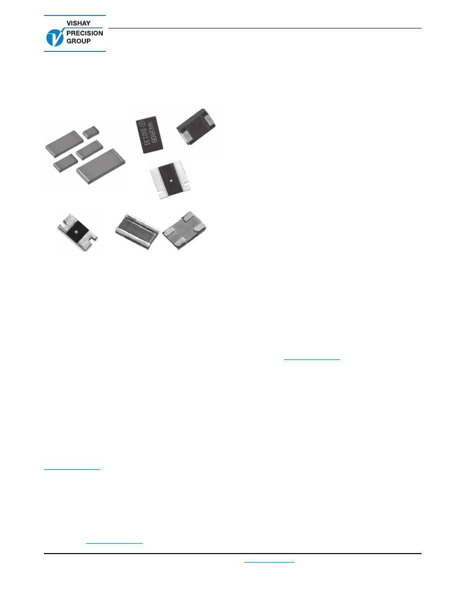
Ultra High Precision Vishay Foil Surface Mount Resistors

Military and Space Applications

Vishay Foil Resistors


Document Number: 63147

For any questions, contact: 

foil@vishaypg.com

www.foilresistors.com

Revision: 06-May-10

1

INTRODUCTION

Many manufacturers and users of precision electronic
equipment suffer unnecessarily with unexplained instabilities
and drifts. They resign themselves to the need for constant
adjustments and troubleshooting which could in fact be
avoided.

Often the instability is traceable to a few “fixed” resistors
which are not fixed at all. If these resistors would only retain
their original values, there would be no need for costly
controls and other compensating circuitry.

The answer? A real precision and stable resistor.

Some precision resistors offer you tight tolerance at the
expense of poor load life stability (1000 h or more), thermal
stabilization and ESD sensitivity, others offer low TCR at the
expense of poor rise time.

Only Vishay Bulk Metal

®

 Foil resistors offer you the complete

set of top performance characteristics, including TCR as low
as 0.2 ppm/°C with the Z-foil technology, a combination that
will most often free your equipment from that tormenting bug.

Vishay now offers you the chance to make your own custom
bulk-metal resistors for breadboard, prototype, or even
production use.

Call or write for information about our resistors:

foil@vishaypg.com

APPLICATIONS

Dc-to-dc converters, feedback circuits, precision amplifiers in
test and measurement instrumentation, medical systems,
satellites and aerospace systems, commercial and military
avionics, weapons systems, audio systems, and
high-temperature systems including down-hole drilling.

How to order: 

foil@vishaypg.com

FEATURES

Temperature coefficient of resistance (TCR) from
0.2 ppm/°C (military range) with the Z-foil technology

Load life stability: to 0.005 % at + 70 °C, at rated power for
more than 10 000 h

Tolerance: best to 0.01 %

Power coefficient (

Δ

R due to self heating): to 5 ppm at

rated power for Z-foil resistors

Resistance range: from 2 m

Ω

Vishay Foil resistors are not restricted to standard values,
we can supply specific “as required” values at no extra cost
or delivery (e.g. 1K2345 vs. 1K)

Electrostatic discharge (ESD) immunity up to 25 000 V

Fast terminal stabilization < 1 s

Rise time: 1 ns effectively no ringing

Thermal EMF < 0.1 µV/°C (Seebeck effect), especially
critical for low resistive value in DC current/voltage

Special non inductive and non capacitive design

The short time overload test is also part of the standard
production process (100 %)

Vishay Foil resistors have been radiation tested

There are four main factors which should be considered
when designing a board: TCR, PCR, thermal EMF and
ESD. Vishay Foil resistors provide the best combination of
the above factors

Data package and test results are available, please
contact us (

foil@vishaypg.com

)

ABOUT THE VISHAY BULK METAL FOIL 
RESISTOR

Vishay low cost high precision Bulk Metal Foil resistors are
the result of an improved concept in resistor manufacturing:
a proprietary Bulk Metal Foil of known and controllable
properties is applied to a special ceramic substrate.

A resistive pattern is then photo-etched by an ultra-fine
technique developed by Vishay. This process results in
resistor element characteristics of low TCR, long term
stability, non inductive, excellent thermal stabilization, low
capacitance and low noise.

The Bulk Metal Foil is a special alloy chosen for its electrical
mechanical and thermal characteristics. It is set on the
substrate by a unique and proprietary process which does
not subject the resistor element to the metallurgical changes
that occur during the winding of wire, or during the
evaporative process used in other forms of resistor
manufacturing. Because the alloy in the Vishay resistor is not
drawn, wound, work hardened, or stressed in any way during
manufacturing process, the resistor maintains all of its

milspace-html.html
background image

Military and Space Applications

Vishay Foil Resistors


www.foilresistors.com

For any questions, contact: 

foil@vishaypg.com

Document Number: 63147

2

Revision: 06-May-10

original design, physical and electrical characteristics. The
temperature coefficient of the resistor is carefully controlled
through compensating techniques which essentially
eliminates the effects of the different coefficients of
expansion of the materials used in the resistor.

CUSTOM PRODUCT DESIGN

Customers who require additional performance tests are
encouraged to contact our application engineers. Our highly
trained application engineers are available to provide
technical assistance and can help in developing source
control drawings (SCD) which define the proper PMO (post
manufacturing operations) needed to achieve optimum
component reliability, stability and performance. Examples
for PMO tests include: short time overload, power
conditioning, thermal shock, thermal conditioning, etc.

POST MANUFACTURING OPERATIONS
OR PMO

Military applications can include requirements for
performance under conditions of stress beyond the normal
and over extended periods of time. This calls for more than
just selecting a standard device and applying it to a circuit.
The standard device may turn out to be all that is needed but
an analysis of the projected service conditions should be
made and it may well dictate a routine of stabilization
known as post manufacturing operations or PMO. The PMO
operations that will be discussed are only applicable to Foil

resistors. They stabilize Foil resistors while they are harmful
to other types.

Short time overload, accelerated load life, and temperature
cycling are the three PMO exercises that do the most to
remove the anomalies down the road. Foil resistors are
inherently stable as manufactured. These PMO exercises
are only of value on foil resistors and they improve the
performance by small but significant amounts. Users are
encouraged to contact Vishay Foil applications engineering
for assistance in choosing the PMO operations that are right
for their application.

PRODUCTION

Vishay Foil resistors are manufactured in a modern plants
complex under exacting conditions of cleanliness. White
rooms are used in several stages of production. The entire
process is under close quality control surveillance.

Batch handling, similar to the process used in semiconductor
manufacture, ensures uniform quality. Each resistor element
is inspected and processed under high magnification
microscopes.

All materials used in the resistor and in the manufacturing
process are carefully controlled and inspected, with
permanent records maintained. All units are tested
electrically, mechanically and visually for conformance to
specifications.

The resistors are delivered in ESD approved packaging.

Notes

(1)

DSCC (Defense Supply Center Columbus)

(2)

EEE-INST-002 (Instruction for EEE Parts Selection, Screening, Qualification, and Derating)

(3)

EPPL (European Preferred Parts List)

• All the above resistors are also available on the shelf as standard products

TABLE 1 - DSCC, EEE-INST-002, AND EPPL

(In accordance with: MIL-PRF-55342, MIL-PRF-55182, MIL-PRF-49465)

TYPE

CONSTRUCTION

DSCC

 (1)

EEE-INST-002

 (2)

EPPL

 (3)

TYPICAL TCR MIL RANGE 

(ppm/°C)

TYPICAL LOAD LIFE 

STABILITY 2000 h

VSMP0805

Wrap around 

terminations

07024

0.2

0.005 %

VSMP1206

07025

VSMP1506

03010

VSMP2010

06001

VSMP2512

06002

VSM0805

07024

2

VSM1206

07025

VSM1506

03010

VSM2010

06001

VSM2512

06002

SMR1DZ

Molded, flexible 

terminations

with robust 

construction

06020

0.2

SMR1D

06020

2

SMR3DZ

06021

0.2

SMR3D

06021

2

VCS1625Z

Current sense with 
Kelvin connections 

for a high accuracy

08003

0.2

VCS1625

08003

2

VCS1610

TBD

CSM2512

07011

15 maximum

0.05 %

CSM3637

07012

milspace-html.html
background image

Military and Space Applications

Vishay Foil Resistors


Document Number: 63147

For any questions, contact: 

foil@vishaypg.com

www.foilresistors.com

Revision: 06-May-10

3

FIGURE 1 - TRIMMING TO VALUES 

(Conceptual Illustration)

TABLE 2 - VSMP0805 (Z-FOIL) SPACE QUALIFICATION TEST RESULTS PER 

MIL-PRF-55342H VALUE 5K

GROUP

TESTS

CONDITIONS

AVERAGE 

Δ

(ppm)

MAXIMUM 

Δ

(ppm)

MINIMUM 

Δ

(ppm)

ACC./REJ.

I

Visual inspection

X

X

X

84/0

DC resistance

X

X

X

84/0

II

Resistance to soldering heat

per MIL-PRF-55342

28

45

14

10/0

TCR

at - 55 °C to + 25 °C

- 0.84

- 0.48

- 1.41

10/0

TCR

at + 25 °C to + 125 °C

0.23

0.50

- 0.08

10/0

Low temperature operation

- 65 °C at P

nom

, 45 min

- 27

- 17

- 33

10/0

Overload

at 6.25 x P

nom

,  5 s

47

60

37

10/0

High temperature operation

100 h at + 150 °C

- 31

- 13

- 55

10/0

III

Resistance to soldering heat

per MIL-PRF-55342

56.70

70

42

10/0

Moisture

MIL-STD-202, method 106

- 241

- 224

- 261

10/0

IV

Load life:

250 h

3.47

24

- 30

34/0

500 h

at 0.2 W at + 70 °C

- 1.38

19

- 32

34/0

1000 h

- 6.56

16

- 38

34/0

2000 h

- 5.94

22

- 35

34/0

V

Solderability

at + 245 °C

X

X

X

10/0

VI

Solderable mounting integrity

30 s at 2 kg

X

X

X

10/0

VIII

Thermal shock

100 x (- 65 °C to + 150 °C)

- 5

10

- 10

10/0

M

u

t

u

al Ind

u

ctance

Red

u

ction d

u

e

to Opposing
C

u

rrent in

Adjacent Lines

C

u

rrent Path

Before Trimming

Note:

 Foil sho

w

n in 

b

lack, etched spaces in 

w

hite

Interloop Capacitance
Red

u

ction in Series

Trimming Process

Remo

v

es this Material

from Shorting Strip Area

Changing C

u

rrent Path

and Increasing

Resistance

C

u

rrent Path

After Trimming

milspace-html.html
background image

Military and Space Applications

Vishay Foil Resistors


www.foilresistors.com

For any questions, contact: 

foil@vishaypg.com

Document Number: 63147

4

Revision: 06-May-10

Note

• Measurement error RC = 0.0005R - should be added to limits

TABLE 3 - CSM2512 EEE-INST-002 QCI PER AER #155518 AND

MIL-PRF-49465C F.C. #294499, VALUE 0R01

GROUP

TESTS

CONDITIONS

AVERAGE 

Δ

(ppm)

MAXIMUM 

Δ

(ppm)

MINIMUM 

Δ

(ppm)

REJ./ACC.

I

Resistance to solvent

MIL-STD-202G, method 215

V

V

V

0/4

II

Thermal shock

5 x (- 65 °C to + 125 °C)

43

120

- 40

0/10

TCR

at - 55 °C to + 25 °C

- 0.08

3.36

- 3.13

0/10

TCR

at + 25 °C to + 125 °C

- 4.86

- 1.69

- 7.70

0/10

Low temperature storage

24 h at - 55 °C

9

20

0

0/10

Overload

at 5 x P

nom

, 5 s

29

60

- 20

0/10

Moisture resistance

10 days

42

70

10

0/10

III

Load life:

at 1 W at + 70 °C

250 h

129

230

30

0/20

500 h

177

290

50

0/20

1000 h

271

420

130

0/20

2000 h

326

520

150

0/20

IV

Thermal shock

5 x (- 65 °C to + 125 °C)

16

40

- 20

0/30

Shock

100 G, 6 ms

0

20

- 30

0/30

Vibration

(10 to 2000 Hz) 20 G

- 8

20

- 40

0/30

V

High temperature exposure

1000 h at + 170 °C

250 h

774

1510

300

0/30

1000 h

1375

2350

780

0/30

FIGURE 2 - VSMP 100 CYCLE THERMAL SHOCK - 65 °C TO + 150 °C, 10 UNITS EACH VALUE

100

Δ

R/R (ppm)

80

60

40

20

0

- 20

- 40

- 60

- 80

- 100

VSMP0805

5K

VSMP2010

10K

VSMP1206

30K

VSMP1206

10K

VSMP2010

100K

VSMP0805

12K

milspace-html.html
background image

Vishay Precision Group

Document No.: 63999

Revision: 27-Apr-2011

www.vishaypg.com

1

Legal Disclaimer Notice

Disclaimer

Legal Disclaimer Notice

Disclaimer

Document No.: 63999

Revision: 27-Apr-2011

ALL PRODUCTS, PRODUCT SPECIFICATIONS AND DATA ARE SUBJECT TO CHANGE WITHOUT NOTICE.

Vishay Precision Group, Inc., its affiliates, agents, and employees, and all persons acting on its or their 
behalf (collectively, “Vishay Precision Group”), disclaim any and all liability for any errors, inaccuracies or 
incompleteness contained herein or in any other disclosure relating to any product.

The product specifications do not expand or otherwise modify Vishay Precision Group’s terms and 
conditions of purchase, including but not limited to, the warranty expressed therein.

Vishay Precision Group makes no warranty, representation or guarantee other than as set forth in the terms 
and conditions of purchase. 

To the maximum extent permitted by applicable law, Vishay Precision 

Group disclaims (i) any and all liability arising out of the application or use of any product, (ii) any and 
all liability, including without limitation special, consequential or incidental damages, and (iii) any and 
all implied warranties, including warranties of fitness for particular purpose, non-infringement and 
merchantability.

Information provided in datasheets and/or specifications may vary from actual results in different 
applications and performance may vary over time. Statements regarding the suitability of products for 
certain types of applications are based on Vishay Precision Group’s knowledge of typical requirements that 
are often placed on Vishay Precision Group products. It is the customer’s responsibility to validate that a 
particular product with the properties described in the product specification is suitable for use in a particular 
application.

No license, express, implied, or otherwise, to any intellectual property rights is granted by this document, or 
by any conduct of Vishay Precision Group.

The products shown herein are not designed for use in life-saving or life-sustaining applications unless 
otherwise expressly indicated. Customers using or selling Vishay Precision Group products not expressly 
indicated for use in such applications do so entirely at their own risk and agree to fully indemnify Vishay 
Precision Group for any damages arising or resulting from such use or sale. Please contact authorized 
Vishay Precision Group personnel to obtain written terms and conditions regarding products designed for 
such applications.

Product names and markings noted herein may be trademarks of their respective owners.