ULTRAFAST RECTIFIER
VOLTAGE RANGE 200 to 600 Volts CURRENT 1.0 Ampere
MAXIMUM RATINGS AND ELECTRICAL CHARACTERISTICS
Ratings at 25
o
C ambient temperature unless otherwise specified.
Single phase, half wave, 60 Hz, resistive or inductive load.
For capacitive load, derate current by 20%.
MURS120
MURS140
MURS160
MAXIMUM RATINGS
(@ T
A
=25
O
C unless otherwise noted)
ELECTRICAL CHARACTERISTICS
(@T
A
=25
O
C unless otherwise noted)
FEATURES
* High reliability
* Low leakage
* Low forward voltage
* High current capability
* Ultrafast switching speed
* High surge capability
* Good for switching mode circuit
MECHANICAL DATA
* Case: Molded plastic
* Epoxy: Device has UL flammability classification 94V-O
* Lead: MIL-STD-202E method 208C guaranteed
* Mounting position: Any
* Weight: 0.057 gram
RATINGS
Maximum Recurrent Peak Reverse Voltage
Maximum RMS Voltage
Maximum DC Blocking Voltage
Maximum Average Forward Rectified Current
at T
A
=55
O
C
Peak Forward Surge Current 8.3 ms single half sine-wave
superimposed on rated load (JEDEC method)
SYMBOL
V
RRM
V
DC
I
FSM
T
J
, T
STG
V
RMS
UNITS
Volts
Volts
Amps
1.0
35
Amps
0
C
Operating and Storage Temperature Range
I
O
-55 to + 150
Volts
MURS120
MURS140
400
200
400
200
280
140
600
MURS160
MURS120
MURS140
MURS160
600
420
NOTES : 1. Test Conditions: I
F
= 0.5A, I
R
= -1.0A, I
RR
= -0.25A
2. "Fully ROHS complaint", "100% Sn plating (Pb-free)"
2010-02
REV: O
CHARACTERISTICS
at Rated DC Blocking Voltage
Maximum Reverse Recovery Time (Note 1)
V
F
SYMBOL
I
R
nSec
uAmps
Maximum DC Reverse Current
Maximum Instantaneous Forward Voltage at 1.0A DC
Volts
5.0
25
@T
J
= 150
o
C
@T
J
= 25
o
C
trr
0.875
1.25
150
2.0
50
50
UNITS
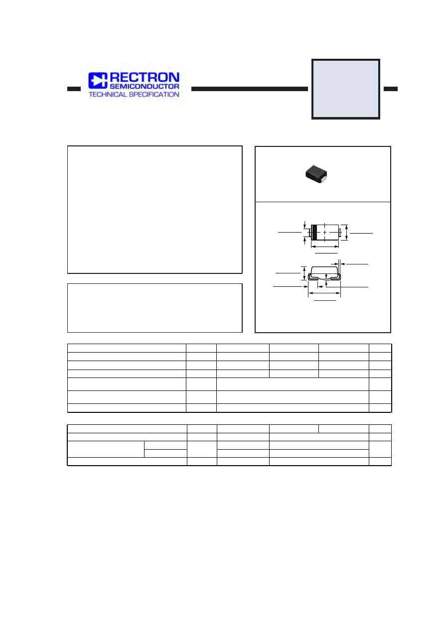
DO-214AA
Dimensions in inches and (millimeters)
.012 (.305)
.006 (.152)
.008 (.203)
.004 (.102)
.220 (5.59)
.205 (5.21)
.030 (0.76)
.060 (1.52)
.084 (2.13)
.096 (2.44)
.160 (4.06)
.180 (4.57)
.130 (3.30)
.155 (3.94)
.083 (2.11)
.077 (1.96)
Pre
lim
ina
ry