ETALDOC 231/7
Page 1 of 4
January 2001
PRODUCT DATA SHEET
MICROPROFILE LINE ISOLATING
P3000
HYBRID
Features
Applications
∗
Surface mount
∗
V.34, V.90 and V.92 Modems
∗
7mm seated height
∗
Miniature DAA applications
∗
Low loss
∗
Universal DAA applications
∗
Low Distortion
∗
Notebook PC Fax/Modems
∗
2-4 wire conversion
∗
CODEC interface
∗
IEC 950, UL 1950 and EN 60950 certified
∗
UL Recognized Component
∗
BABT Certificate of Recognition
∗
CSA NRTL/C Certificate of Compliance
DESCRIPTION
P3000 is a microprofile passive hybrid module for
applications where reinforced insulation is required.
It features fully vacuum encapsulated construction
using materials conforming to UL94V-0 flammability
requirements.
P3000 performs the functions of reinforced safety
barrier (3750Vrms), telephone line matching and 2-4
wire conversion. This component is designed
specifically for high speed full-duplex data
transmission where very low levels of distortion are
required and where the transmission spectral
density is mainly confined to the band 600Hz - 3kHz,
(e.g. V.32bis and faster). Operation at
56kbits/second has been confirmed. The high
performance is achieved by realizing a very low
noise floor at the receive port even when the power
sourced at the transmit port is high. Circuit
simplification is readily achieved as the transmit,
receive and line ports are fully floating and
galvanically isolated from each other.
P3000 is readily matched to complex reference
impedances and with the major benefit that the
impedance matching components are all on the
line side of the safety barrier. Furthermore, the
transmit and receive frequency responses are
very flat (i.e. negligible 'twist') when matched to
complex impedances.
For best operation the module requires a transmit
drive from a high-quality low-impedance source
(«10
Ω
), and a high impedance receive load (47k
Ω
nominal). These impedances may be directly
provided by data pumps and CODECs.
P3000 is also useful for voice applications
requiring 2-4 wire conversion as its port
impedances are particularly suitable for CODECs.
P3000 is certified to IEC 950, EN 60950,
EN 41003, and UL1950. P3000 is a UL
Recognized Component, and is supported by a
BABT Certificate of Recognition, a CSA Certificate
of Compliance and an IEC CB Test Certificate.
Patented
E203175
to Electronic Techniques
(Anglia) Limited
P3000
ETALDOC 231/7
Page 2 of 4
January 2001
SPECIFICATIONS
Electrical
At T = 25ºC and as reference circuit Fig. 2 unless otherwise stated.
Parameter
Conditions
Min
Typ
Max
Units
Insertion Loss
TX port (1,3) to line port (9,10)
TX port (1,3) to line terminals (matching
loss included)
Line terminals to RX port (4,6)
-
-
-
1.8
6.2
2.8
-
-
-
dB
dB
dB
Frequency Response
TX port to line port 200Hz – 4kHz
TX port to line terminals 300Hz – 3.4kHz
Line terminals to RX port 300Hz – 3.4kHz
-
-
-
±0.05
±0.1
±0.1
-
-
-
dB
dB
dB
Transhybrid loss
300Hz – 3.4kHz
-
>30
-
dB
Return Loss
300Hz – 3.4kHz
-
>17
-
dB
Distortion
(1)(2)
TX signal splashback
distortion at RX port
Harmonic
Fundamental
≥
600Hz @ 0dBm in line
-
≤
-90
-
dBm
Intermodulation
Tones 1.5kHz, 2.1Hz total 0dBm in line
-
<-90
-
dBm
RX signal distortion at
RX port
Harmonic
Fundamental
≥
600Hz @ 0dBm in line
-
≤
-90
-
dBm
Intermodulation
Tones 1.5kHz, 2.1Hz total 0dBm in line
-
≤
-90
-
dBm
TX signal distortion at
line terminals
Harmonic
Fundamental
≥
600Hz @ 0dBm in line
Fundamental
≥
600Hz @ -6dBm in line
-
-
≤
-65
≤
-80
-
-
dBm
dBm
Intermodulation
Tones 1.5kHz, 2.1Hz total 0dBm in line
-
-70
-
dBm
Voltage Isolation
(3)
50Hz
DC
3.88
5.5
-
-
-
-
kVrms
kV
Operating Range:
Functional
Storage
Ambient
-25
-40
-
-
+85
+125
ºC
ºC
Notes:
1. For optimum distortion performance DC
currents through pins 1 and 3 should not
exceed 50µA, and currents through pins 4 and
6 should not exceed 3µA. DC resistance
between pins 1-3, 115
Ω
nominal. DC
resistance between pins 4-6, 1.6k
Ω
nominal.
2. Caution: do not pass DC through P3000.
Telephone line current etc. must be diverted
using semiconductor line hold circuit.
3. Components are 100% tested at 6.5kVDC.
P3000
ETALDOC 231/7
Page 3 of 4
January 2001
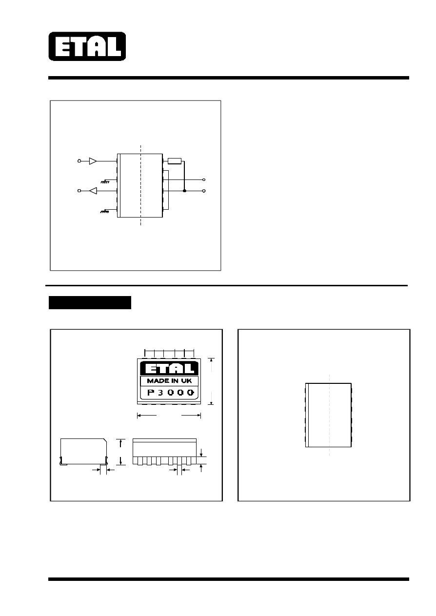
CONSTRUCTION
Geometric centres of outline and pin grid coincide within a tolerance circle of 0.6mmØ.
SAFETY
BARRIER
1
12
11
10
LINE
CODEC
TX
RX
9
8
7
2
3
4
5
6
Notes:
1. Maximum recommended Zout of TX amplifier = 10 ohms
2. Zin of RX amplifier = 47k ohms preferred, minimum 10k ohms
3. Circuit values match to 600 ohm lines only. See P3000
application notes for other line impedances.
600 ohm circuit
Fig. 1
390R
2.54 2.54
2.54
3.18
2.54
12.7
(0.5)
17.6 max
(0.69)
Pad 1
7.0 max
(0.28)
1.5
(0.06)
1.77
(0.07)
(0.1) (0.1)
(0.1) (0.1)
(1.25)
NOTE: Dimensions shown are in millimetres (inches)
Dimensions
Fig. 2
1.32
(0.052)
SAFETY
BARRIER
1
12
11
10
9
8
7
2
3
4
5
6
RX-
N.C.
RX+
TX-
N.C.
TX+
ZT
REF OUT
LINE -
LINE +
N.C.
REF IN
(Viewed from top)
Connections
Fig. 3
P3000
ETALDOC 231/7
Page 4 of 4
January 2001
SAFETY
CERTIFICATION
Manufactured from materials conforming to
flammability requirements of UL94V-0 and
EN 60950:1992 (BS
7002:1992) sub-clause
1.2.13.2 (V-0).
Distance through reinforced insulation 0.4mm
minimum.
Creepage and clearances in circuit are 7mm
minimum where PCB pads do not exceed 3mmØ.
Constructed and fully encapsulated in accordance
with EN 60950:1992 (BS 7002:1992) IEC950:1991
and BS EN 41003:1997 (reinforced), 250Vrms
maximum working voltage.
Certified by BSI to IEC 950:1991/A4:1996
(IEC CB Test Certificate No. GB441W) sub-
clauses 1.5, 1.5.1, 1.5.3, 2.2, 2.2.2, 2.2.3, 2.2.4,
2.9.2, 2.9.3, 2.9.4, 2.9.6, 2.9.7, 4.4, 4.4.3.2 (class
V-0) and 5.3 for a maximum working voltage of
250Vrms, nominal mains supply voltage not
exceeding 250Vrms and a maximum operating
temperature of +85ºC in Pollution Degree 2
environment, reinforced insulation.
CAN/CSA C22.2 No. 950-95/UL1950, certified by
CSA, Third Edition, including revisions through to
revision date March 1, 1998, based on Fourth
Amendment of IEC 950, Second Edition, maximum
working voltage 250Vrms, Pollution Degree 2,
reinforced insulation.
UL File number E203175.
CSA Certificate of Compliance 1107696 (Master
Contract 1188107).
Certified by BABT to EN 60950.
BABT Certificate CR/0139.
Additionally, Profec Technologies certifies all
transformers as providing voltage isolation of
3.88kVrms, 5.5kV DC minimum. All shipments
are supported by a Certificate of Conformity to
current applicable safety standards.
ABSOLUTE MAXIMUM RATINGS
COPYRIGHT
(Ratings of components independent of circuit).
Short term isolation voltage (15s)
Storage temperature
Soldering temperature profile
peak -
either
or
or
4.6 kVrms,
6.5kVDC
-40ºC to
+125ºC
240ºC
60s
250ºC
30s
260ºC
10s
ETAL, and P3000 are Trade Marks of Profec
Technologies Ltd.
The Trade Mark ETAL is registered at the UK
Trade Marks Registry.
The concept, design and circuit embodiment of
components such as P3000 are patented. No
patent rights or licences to any circuits or products
described herein are implied or granted to any
third party.
British Patent No. 2270241
France Patent No. 2696063
US Patent No. 5426697
Germany Patent No. DE 4329519
Hong Kong Patent No. HK 1004044
Singapore Patent No. 9791629-0
© 1997 and 2000 Profec Technologies Ltd.
Reproduction prohibited.
T R A N S F O R M I N G T H E F U T U R E
Profec Technologies Ltd., 10 Betts Avenue, Martlesham Heath, Ipswich, IP5 3RH, England
Telephone: +44 (0) 1473 611422
Fax: +44 (0) 1473 611919
Websites: www.etal.ltd.uk
www.profec.com
Email:
info@etal.ltd.uk
sales@profec.com
Patented
ISO 9001
FM 25326