SURFACE MOUNT GPP
TRANSIENT VOLTAGE SUPPRESSOR
400 WATT PEAK POWER 1.0 WATTS STEADY STATE
MAXIMUM RATINGS AND ELECTRICAL CHARACTERISTICS
TVS
P4FMAJ
SERIES
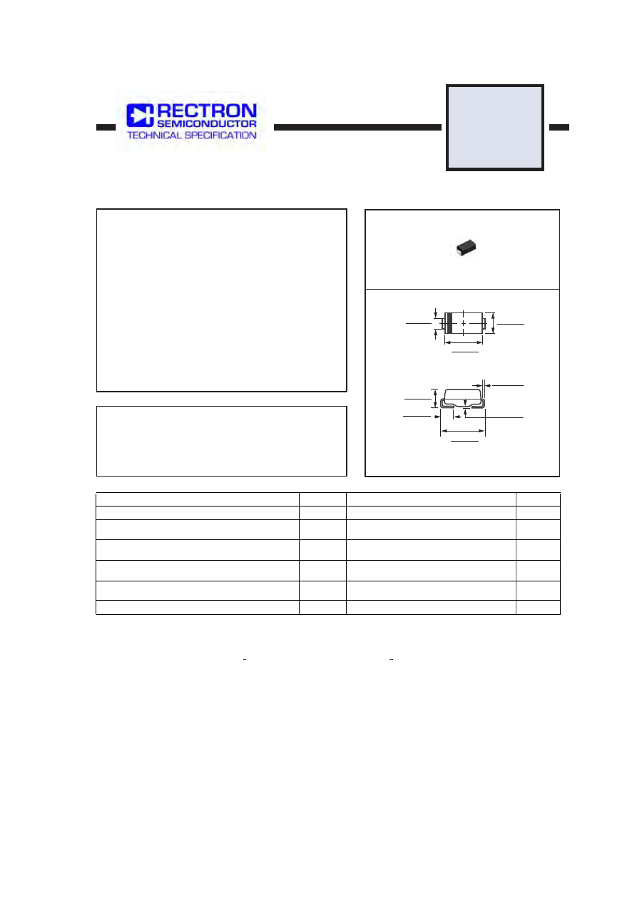
DO-214AC
MAXIMUM RATINGS
(@ T
A
=25
O
C unless otherwise noted)
Dimensions in inches and (millimeters)
FEATURES
* Plastic package has underwriters laboratory
* Glass passivated chip construction
* 400 watt surage capability at 1ms
* Excellent clamping capability
* Low zener impedance
* Fast response time
RATINGS
Steady State Power Dissipation at T
L
= 75
O
C lead length,
.375" (9.5 mm) (Note 2)
Peak Forward Surge Current, 8.3ms single half sine wave-
superimmposed on rated load ( JEDEC METHOD ) (Note 3)
Maximum Instantaneous Forward Voltage @25A for unidirectional
only
SYMBOL
P
M(AV)
I
FSM
V
F
T
J
, T
STG
V
-55 to + 150
0
C
UNITS
( Note 5 )
A
Peak Power Dissipation at T
A
= 25
O
C,T
P
= 1mS (Note 1)
Minimum 400
1.0
SEE TABLE 1
40
3.5/6.5
W
VALUE
Operating and Storage Temperature Range
P
PPM
W
Ratings at 25
o
C ambient temperature unless otherwise specified.
Single phase, half wave, 60 Hz, resistive or inductive load,
For capacitive load, derate current by 20%.
2013-01
REV: O
NOTES :
4. "Fully ROHS compliant", "100% Sn plating (Pb-free)".
0.091 ( 2.31 )
0.067 ( 1.70 )
0.012 ( 0.305 )
0.006 ( 0.152 )
0.008 ( 0.203 )
0.004 ( 0.102 )
0.059 ( 1.50 )
0.035 ( 0.89 )
0.209 ( 5.31 )
0.185 ( 4.70 )
0.180 ( 4.57 )
0.160 ( 4.06 )
0.110 ( 2.79 )
0.086 ( 2.18 )
0.067 (1.70 )
0.051 (1.29 )
3. Measured on 8.3mS single half Sine-Wave or equivalent wave, duty cycle = 4 pulses per minute maximum.
2. Mounted on 0.2 X 0.2” (5.0 X 5.0mm) copper pad to each terminal.
Peak Pulse Current with a 10/1000uS waveform
( Note 1, Fig.3 )
I
PPM
A
1. Non-repetitive current pulse, per Fig.3 and derated above TA = 25
o
C per Fig.2.
5. VF = 3.5V max. for devices of V(BR) < 200V and VF = 6.5V max. for devices of V(BR) > 200V.