16
Disc Ceramic Capacitors
General Specifications - Class III General Purpose
Measured at
1.0 kHz / 0.1 Vrms / 25ºC
Dissipation C
R
≤
22 nF
→
Y5V, Y5U
≤
7.5%
Factor
C
R
> 22 nF
→
Y5V, Y5P
≤
5.0%
Capacitance
Y5P
→
±20% / -20 +50%
Tolerance
Y5U
→
±20% / -20 +80%
Y5V
→
±20% / -20 +80%
Climatic
30 / 085 / 21
Category
Insulation
Y5P
≥
12 M
Ω
Resistance
Y5U
4.7 nF...100 nF
→ ≥
10 M
Ω
@ V
R
200 nF
→ ≥
1 M
Ω
Y5V
≥
100 M
Ω
Dielectric Strength
Between
Vt = 1.25 V
R
NOTE: Charging
leads
current limited
Body
V
R
= 25V Vt = 100V (DC)
to 50 mA
insulation
V
R
= 50V Vt = 150V (DC)
Operating
Temperature
-30... +85
Range (ºC)
PERFORMANCE CHARACTERISTICS CLASS III
Note: Damp Heat Steady State: 90... 95% R.H. 40ºC / 21 days. No voltage to be applied.
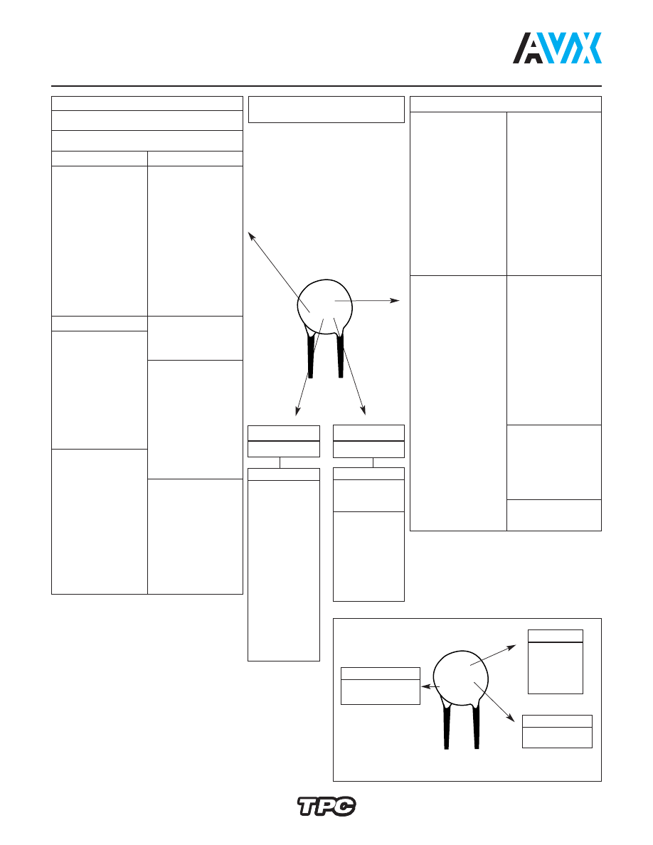
DIELECTRIC - CLASS III
A thin dielectric layer is grown on a disc of conductive
ceramic. Very large capacitances can be obtained due to
reduced thickness of this barrier layer and its inherently
high dielectric constant. Due its small dimensions, they
are a less expensive replacement of multilayer ceramic or
polyester capacitors. An equivalent circuit is shown below:
Meets IEC 324 (1970).
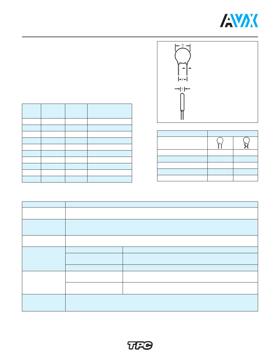
DIMENSIONS
millimeters (inches)
Digit 9
Available
of P.N.
D ± 2
T max.
Lead Spacing
(ø)
(0.079)
A
4.0 (0.157)
3.0 (0.118)
A,B,D,E,O,R
B
5.0 (0.197)
3.0 (0.118)
A,B,D,E,O,R,X
C
6.0 (0.236)
3.0 (0.118)
A,B,C,D,E,O,R,X
D
7.0 (0.276)
3.0 (0.118)
A,B,C,D,E,O,R,X
E
8.0 (0.315)
3.0 (0.118)
A,B,C,D,E,O,R,X
F
9.0 (0.354)
3.0 (0.118)
A,B,C,E,O,R,X
G
10.0 (0.394) 3.0 (0.118)
A,B,C,E,O,R,X
H
11.0 (0.433) 3.0 (0.118)
A,B,C,E,O,R,W
J
13.0 (0.512) 3.5 (0.138)
B,C,R,W
K
15.0 (0.591) 4.0 (0.157)
B,C,R,W
Lead Spacing
Digit 8 of P.N.
F
2.5 (0.100)
D
—
5 (0.200)
A
O
6 (0.250)
E
X
7.5 (0.300)
B
R
10 (0.400)
C
W
Preferred lead spacing
F = 5 (0.197)
Ø = 0.6 ± 0.1
(0.024) (0.004)
millimeters (inches)
pa/AVX/Capacitors/Ceramic/Disc/AVX_Disc_Ceramic_Capacitors_Dielectric_classIII-html.html
17
Disc Ceramic Capacitors
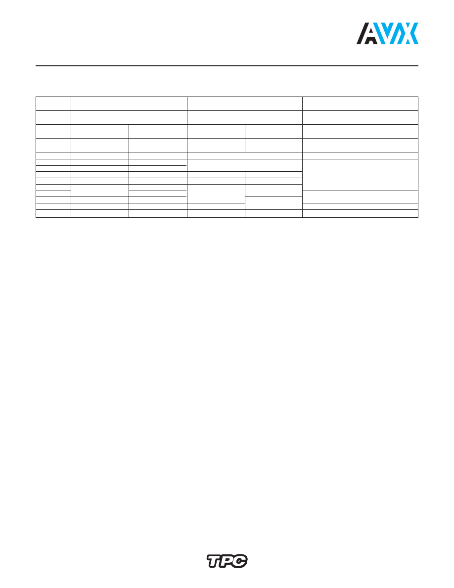
Dimension Table
Barrier Layer Capacitors - Class III General Purpose
PHENOLIC COATED – CAPACITANCE VS. DISC DIAMETER
millimeters (inches)
Y5U, Y5V - Preferences
Diameter (
φ
) = 9th Part Number Digit
Class III
∆
C/C (max.)
Range
∆
C/C (max.)
Range
∆
C/C (max.)
Range
±12%
-30... +85ºC
+30 -65%
-30... +85ºC
+22 -85%
-30... +85ºC
Temp.
Y5P
Y5U
Y5V
Coefficient
Digits 1,2,3
5WF
5WH
5YF
5YH
5ZH
of P.N.
Rated
25 VDC
50 VDC
25 VDC
50 VDC
50 VDC
Voltage (V
R
)
C
R
(pF)
4,700
4.0 (0.157)
4.0 (0.157)
4.0 (0.157)
4.0 (0.157)
10,000
6.0 (0.236)
6.0 (0.236)
22,000
7.0 (0.276)
8.0 (0.315)
5.0 (0.197)
6.0 (0.236)
4.0 (0.157)
33,000
8.0 (0.315)
9.0 (0.354)
6.0 (0.236)
7.0 (0.276)
47,000
11.0 (0.433)
50,000
10.0 (0.394)
—
7.0 (0.276)
8.0 (0.315)
68,000
11.0 (0.433)
13.0 (0.512)
5.0 (0.197)
100,000
13.0 (0.512)
15.0 (0.591)
8.0 (0.315)
9.0 (0.354)
7.0 (0.276)
200,000
—
—
13.0 (0.512)
—
pa/AVX/Capacitors/Ceramic/Disc/AVX_Disc_Ceramic_Capacitors_Dielectric_classIII-html.html
4
5
General Purpose
5A = NP0 / I
*5B = P100 / I
*5C = N150 / I
*5D = N220 / I
*5E = N330 / I
*5F = N470 / I
5G = N750 / I
5H = N1500 / I
*5I = N2200 / I
*5J = N4700 / I
5K = SL
5M = Y5E / II
5N = Y5F / II
5O = Y5P / II
*5P = Y5R / II
*5Q = Y5T / II
5S = Y5U / II
5T = Y5V / II
5U = Z5V / II
*5V = Z4V / III
5W = Y5P / III
5Y = Y5U / III
5Z = Y5V / III
O
Professional Switch Mode
Safety
6A = NP0 / I
*6B = P100 / I
*6C = N150 / I
*6D = N220 / I
*6E = N330 / I
*6F = N470 / I
6G = N750 / I
*6H = N1500 / I
*6I = N2200 / I
6J = N4700 / I
61 = SAFETY
62 = SAFETY
65 = SAFETY
67 = Y5U / SM
68 = Y5V / SM
6L = Y5P / SM
6M = X5E / II
6N = X5F / II
6O = X5P / II
*6P = X5R / II
*6Q = X5T / II
6S = X5U / II
6T = X5V / II
6U = Z5V / II
*6V = Z4V / III
6W = Y5P / III
6Y = Y5U / III
6Z = Y5V / III
Q
Rated Voltage (dc)
D = 16V
F = 25V
H = 50V
K = 100V
N = SAFETY
O = SAFETY
Q = 500V
R = 1000V
S = 2000V
T = 3000V
U = 4000V
V = SAFETY
W = 5000V
*X = 6000V
*Y = 7500V
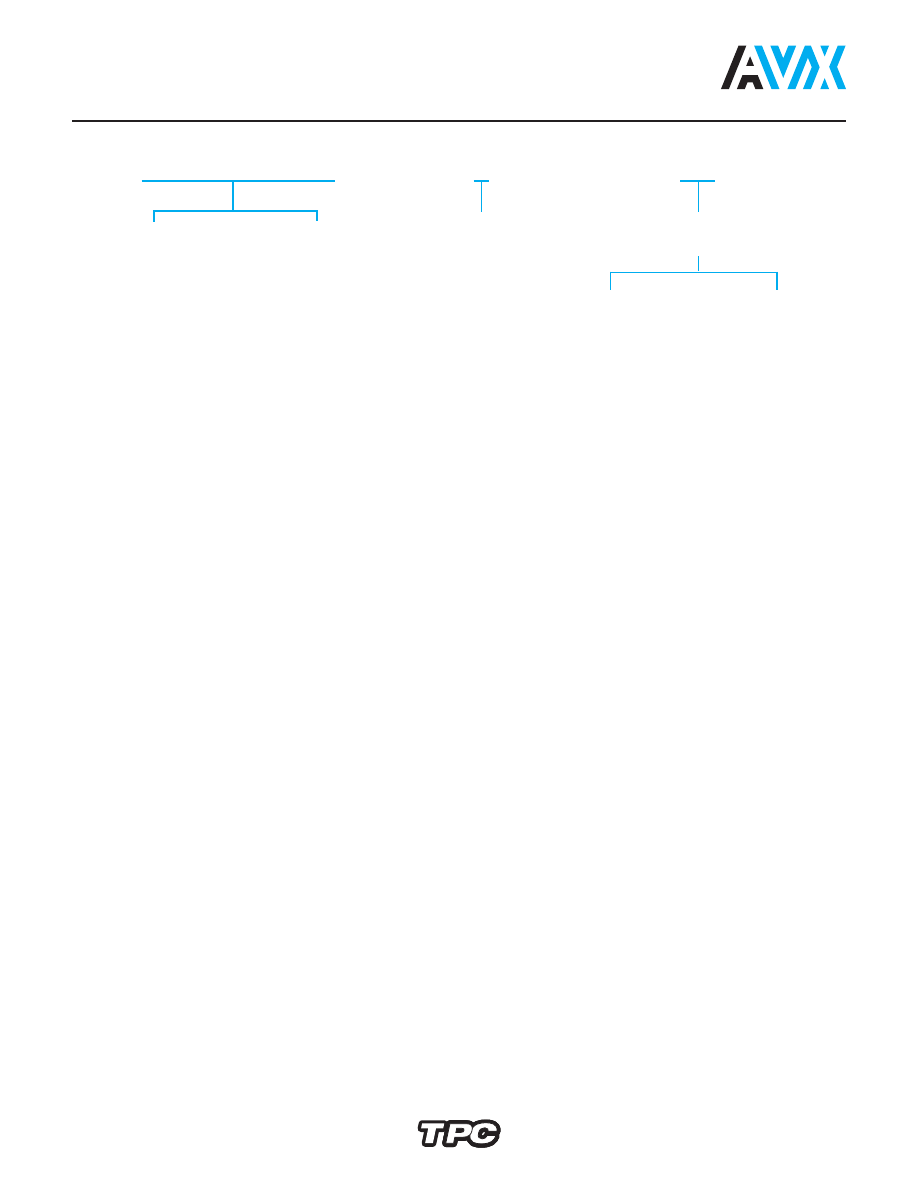
HOW TO ORDER
222
Capacitance
222 = 2.2 nF
Disc Ceramic Capacitors
Ordering Code
Capacitance = TPC code
1 pF = 1R0
1.2pF = 1R2
1.5pF = 1R5
1.8pF = 1R8
2.2pF = 2R2
2.7pF = 2R7
3.9pF = 3R9
4.7pF = 4R7
5.6pF = 5R6
6.8pF = 6R8
8.2pF = 8R2
10pF = 100
12pF = 120
15pF = 150
18pF = 180
22pF = 220
27pF = 270
33pF = 330
39pF = 390
47pF = 470
56pF = 560
68pF = 680
82pF = 820
Capacitance = TPC code
100pF = 101
120pF = 121
150pF = 151
180pF = 181
220pF = 221
270pF = 271
330pF = 331
390pF = 391
470pF = 471
560pF = 561
680pF = 681
820pF = 821
1nF = 102
1.2nF = 122
1.8nF = 182
2.2nF = 222
2.7nF = 272
3.3nF = 332
3.9nF = 392
4.7nF = 472
5.6nF = 562
6.8nF = 682
8.2nF = 822
10nF = 103
15nF = 153
22nF = 223
33nF = 333
47nF = 473
100nF = 104
200nF = 204
*Upon Request
pa/AVX/Capacitors/Ceramic/Disc/AVX_Disc_Ceramic_Capacitors_Dielectric_classIII-html.html
5
M
Tolerance
C = ±0.25 pF
D = ±0.50 pF
J = ±5%
K = ±10%
M = ±20%
S = -20+50%
Z = -20+80%
P = 0+100%
A
E
Capacitor Diameter
± 2 (0.079)
A = 4 (0.157)
B = 5 (0.197)
C = 6 (0.236)
D = 7 (0.276)
E = 8 (0.315)
F = 9 (0.354)
G = 10 (0.394)
H = 11 (0.433)
J = 13 (0.512)
K = 15 (0.591)
M* = 19 (0.748)
A
A
Packaging
Disc Ceramic Capacitors
Ordering Code
Lead Forming
mm
inches
2.5 ±0.5
.1 ± .025
D
–
–
5
+0.6
.2 ± .025
A
O
N
-0.2
6
+0.6
.25 ± .025
E
X
–
-0.2
7.5
+1
.3 ± .05
B
R
Q
-0.5
10
+0.5
.4 ± .05
C
W
–
-1.0
12.5
+1
.5 ± .05
P
–
–
-0.5
Low Voltage
A =
(
General
)
Q = Waxed phenolic
Phenolic
Purpose
S = Epoxy (Professional) cap. diameter
≤
8 (0.315)
D = Epoxy (Professional) cap. diameter
> 8 (0.315)
High Voltage
C = Epoxy wire diameter
0.6
±
0.1
(0.024)
(0.004)
I = Epoxy wire diameter
0.8
±
0.1
(0.031)
(0.004)
L = Phenolic wire diameter
0.6
±
0.1
(0.024)
(0.004)
Finishing
Coating does not
surpass the bend
Diam
≤
9 (0.354) and
F = 5.00 (0.197)
For every other:
Avisert
Panasert
H
L
L
J
L
L
F = Measured
from the
center of
leads
Cardboard Strips
A
=
Bulk
E
= 5 (0.197) ± 1 (0.039) free wire length
C
= 10 (0.394) ± 1 (0.039) free wire length
D
= 25 (0.984) ± 1 (0.039) free wire length
Taping
Reel
Ammo
Pack
Please note that not all code combinations
are either possible or available.
*Wire 0.8 (0.031) recommended
Avisert
Panasert
I
M M
K
M
M
pa/AVX/Capacitors/Ceramic/Disc/AVX_Disc_Ceramic_Capacitors_Dielectric_classIII-html.html
28
Disc Ceramic Capacitors
Marking
DIG. 2
O
TC / Class
General Purpose
A = NP0 / I
*B = P100 / I
*C = N150 / I
*D = N220 / I
*E = N330 / I
*F = N470 / I
G = N750 / I
H = N1500 / I
*I = N2200 / I
*J = N4700 / I
K = SL
M = Y5E / II
N = Y5F / II
O = Y5P / II
P = Y5R / II
Q = Y5T / II
S = Y5U / II
T = Y5V / II
U = Z5V / II
V = Z4V / III
*W = Y5P / II
*X = Y5R / II
Y = Y5U / II
Z = Y5V / II
Professional
A = NP0 / I
B = P100 / I
C = N150 / I
D = N220 / I
E = N330 / I
F = N470 / I
G = N750 / I
H = N1500 / I
I = N2200 / I
J = N4700 / I
7 = Y5U / SM
8 = Y5V / SM
L = Y5P / SM
M = X5E / II
N = X5F / II
O = X5P / II
P = X5R / II
Q = X5T / II
S = X5U / II
T = X5V / II
U = Z5V / II
V = Z4V / III
W = Y5P / III
X = Y5R / III
Y = Y5U / III
Z = Y5V / III
Capacitance
1pF = 109
1.2pF = 129
1.5pF = 159
1.8pF = 189
2.2pF = 229
2.7pF = 279
3.9pF = 399
4.7pF = 479
5.6pF = 569
6.8pF = 689
8.2pF = 829
10pF = 100
12pF = 120
15pF = 150
18pF = 180
22pF = 220
27pF = 270
39pF = 390
47pF = 470
56pF = 560
68pF = 680
82pF = 820
EIA
100pF = 101
120pF = 121
150pF = 151
180pF = 181
220pF = 221
270pF = 271
390pF = 391
470pF = 471
560pF = 561
680pF = 681
820pF = 821
1nF = 102
1.2nF = 122
1.8nF = 182
2.2nF = 222
2.7nF = 272
3.9nF = 392
4.7nF = 472
5.6nF = 562
6.8nF = 682
8.2nF = 822
10nF = 103
15nF = 153
22nF = 223
33nF = 333
47nF = 473
100nF = 104
200nF = 204
Logo: Only in diam.
≥
6mm
DIG. 3
Q
Rated Voltage
D = 16V
F = 25V
H = 50V
K = 100V
Q = 500V
R = 1000V
S = 2000V
T = 3000V
U = 4000V
W = 5000V
X = 6000V
Y = 7500V
Tolerance
C = ±0.25pF
D = ±0.5pF
J = ±5%
K = ±10%
M = ±20%
S = -20 +50%
Z = -20 +80%
P = 0 +100%
DIG. 7
M
Type
61V
620
65N
Tolerance
As above
Capacitance
As above
Safety
Front
Back: (Approval marks)
61V
471M
TC – Temperature coefficient.
DIG – for better understanding, check pages 3 and 4.
222
OQM
*Upon Request
pa/AVX/Capacitors/Ceramic/Disc/AVX_Disc_Ceramic_Capacitors_Dielectric_classIII-html.html
29
29
Disc Ceramic Capacitors
Packaging
TAPED PARTS QUANTITY TABLE
millimeters (inches)
CARDBOARD STRIPS QUANTITY TABLE
millimeters (inches)
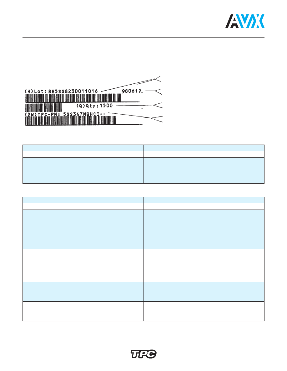
IDENTIFICATION AND TRACEABILITY
On all TPC ceramic capacitors
packages, you will find a bar code label
with the following information:
Rated Voltage
Diameter
Quantities
(Vr)
D
Ammopack
Reel
Vr <= 500V
D
⬉
7 (0.276)
2000
2500
7 < D
⬉
11 (0.433)
2000
2000
500V<Vr<=2KV
D
⬉
11 (0.433)
1500
2000
2KV<Vr=5KV
D
⬉
11 (0.433)
1000
1500
Quantities for other package alternative, upon request.
Lot number
Manufacturing date
Quantity of parts per packaging
Product part number
Rated Voltage
Diameter
Lead Space
(Vr)
D
< = 5 (0.197)
> 5 (0.197)
Vr <= 500V
D
⬉
8 (0.315)
2500
1500
8 (0.315)
⬉
D
⬉
11 (0.433)
1500
-
8 (0.315)
⬉
D
⬉
13 (0.512)
-
1000
11 (0.433)
⬉
D
⬉
15 (0.591)
1000
-
13 (0.512)
⬉
D
⬉
19 (0.748)
-
500
D
⬉
19 (0.748)
500
-
500V<Vr<=2KV
D
⬉
9 (0.354)
1500
1000
9 (0.354)
⬉
D
⬉
11 (0.433)
-
1000
9 (0.354)
⬉
D
⬉
13 (0.512)
1000
-
11 (0.433)
⬉
D
⬉
19 (0.748)
-
500
13 (0.512)
⬉
D
⬉
19 (0.748)
500
-
2KV<Vr<=5KV
D
⬉
9 (0.354)
1500
-
Safety 65N 62O
D
⬉
11 (0.433)
-
1000
D
⬉
13 (0.512)
500
500
Safety
D
⬉
6 (0.236)
1500
1500
61V
7 (0.275)
⬉
D
⬉
9 (0.354)
1000
1000
9 (0.354)
⬉
D
500
500
pa/AVX/Capacitors/Ceramic/Disc/AVX_Disc_Ceramic_Capacitors_Dielectric_classIII-html.html
30
Disc Ceramic Capacitors
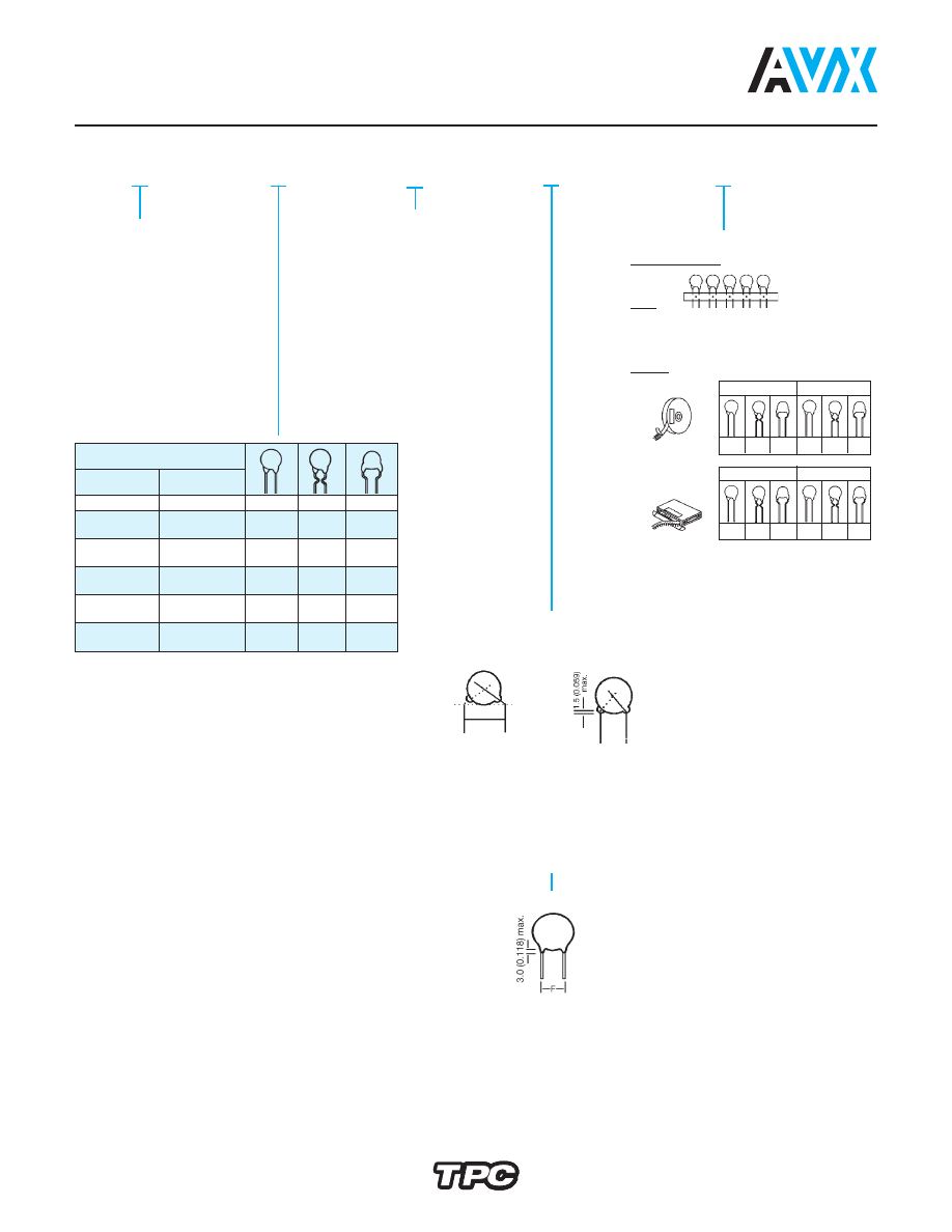
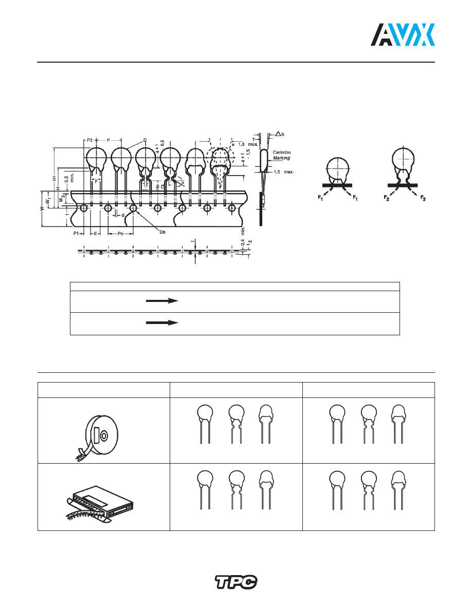
Tape and Reel Specifications
Straight leads
Maximum pull force during insertion and lead cut
F
1
F
2
4 (0.157)
≤
D < 6 (0.236)
12N
20N
D
≥
6 (0.236)
20N
25N
Crimped leads
Digit 11
Available Tapings
Digit 9
L
Sizes
4 (0.157)
≤
D
≤
11 (0.433)
A... H
M
J H
Sizes
6 (0.236)
≤
D
≤
11 (0.433)
C... H
K I
There are two types of taped disc ceramic capacitors:
Straight or crimped leads.
Both types can be shipped on reels or ammopack.
The standard packaging quantities are shown bellow:
TPC Code Digit 11
Packaging
Avisert
Panasert
H
FIGURE 1
L
FIGURE 2
L
FIGURE 3
I
FIGURE 1
M
FIGURE 2
M
FIGURE 3
J
FIGURE 1
L
FIGURE 2
L
FIGURE 3
K
FIGURE 1
M
FIGURE 2
M
FIGURE 3
Ammopack
Reel
Figure 2: Inside Crimp 100V... 1000V
Figure 3: Outside Crimp 1000V
Fig. 1
Fig. 2
Fig. 3
millimeters (inches)
pa/AVX/Capacitors/Ceramic/Disc/AVX_Disc_Ceramic_Capacitors_Dielectric_classIII-html.html
31
Disc Ceramic Capacitors
Tape and Reel Specifications
Straight Leads
Crimped
Figure 1
Figure 2 & 3
Description of Symbols
A (Avisert)
P (Panasert)
Avisert & Panasert
Crimp angle
∝
—
—
20º...45º
Crimp length
C
—
—
1.7 min.
Lead diameter
d
0.60 ± 0.1
Disc diameter
D
11 max.
Lead hole diameter
Do
4.0 ± 0.2
Disc thickness
T
See Catalog
Lead spacing
F
5.0
Component alignment, front-rear
∆
h
0 ± 1
Height of component from tape center
H
19.5 ± 0.5
16.5 ± 0.5 - 0
—
Height from tape center to crimp
Ho
—
—
16 + 0.5 - 0
Component height
H1
32.25 max.
32.25 max.
Distance from component leads to tape bottom
ᐍ
1
12 max.
Tape width
W
18
Bonding tape width
W
3
5.5 min.
Feed hole position
W
1
9.0 ± 0.5
Pitch between discs
P
12.7 ± 1
Feed hole pitch
Po
12.7 ± 0.3
Hole center to lead
P1
3.85 ± 0.7
Feed hole center to component center
P2
6.35 ± 1
Tape + bonding tape thickness
t
0.7 ± 0.2
Total tape thickness. including lead
t
2
1.5 max.
millimeters (inches)
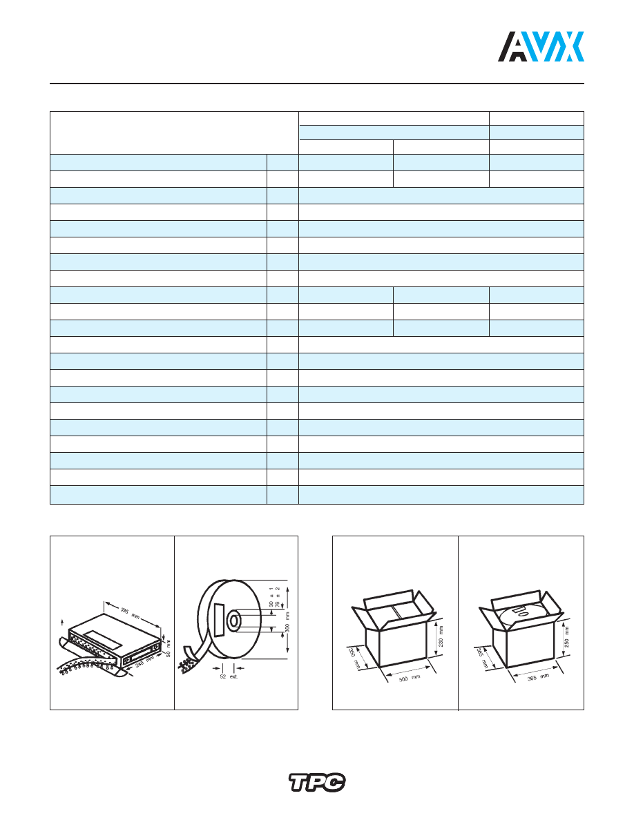
PACKAGING
SHIPPING CONTAINER
Ammopack
Reel
max. stacking: 10 boxes
max. stacking: 10 reels
8 Ammopack
5 Reel
This side up
during storage
and transportation
+0.6
-0.2
+1
-0.5
>23.5
<32.25