background image

ETALDOC 826/3

Page 1 of 3

August 2003

PRODUCT DATA SHEET

HIGH POWER INDUCTOR

P7600 

Family

Features

Applications

 High Current

 DC-DC Converters

  Low Loss, Low DCR

  Voltage Regulator Modules

  Closed magnetic circuit

 Distributed Power

 Low Profile

 Servers

 Pb-free

 Workstations

  Alloy powder core

 Telecom equipment

  Helical rectangular wire

  Notebook and handheld equipment
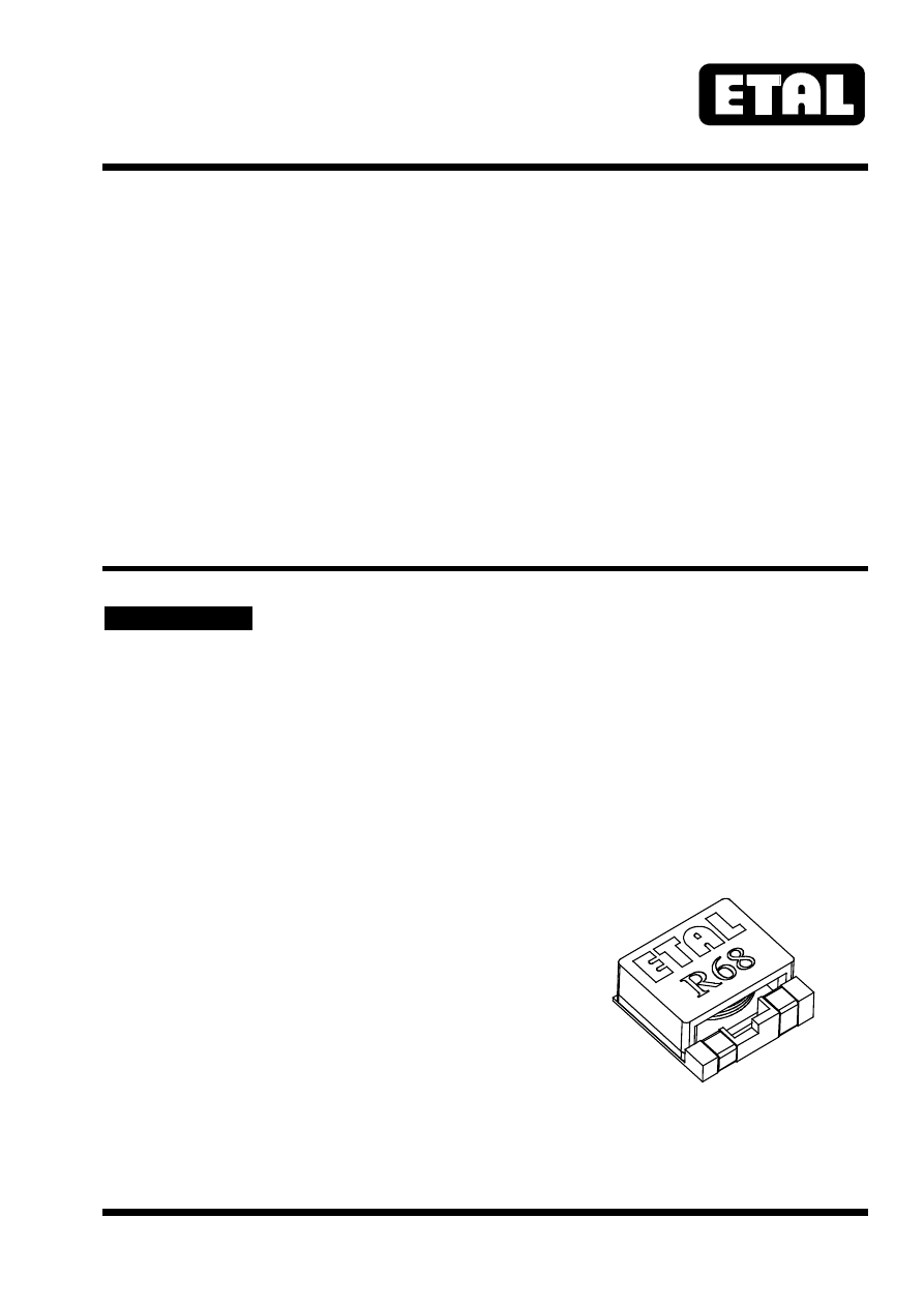


DESCRIPTION

The P7600 family comprises high-energy-density
surface mount inductors.  The family employs
helical windings of rectangular wire, giving
excellent DC resistance, thermal efficiency and
high frequency performance. A distributed gap
powder core is used, yielding stable inductances at
very high currents with a closed magnetic current.

Components are supplied with Pb-free
terminations in tape and reel packaging, and are
suitable for Pb-free and conventional placement
and reflow.

pa/etal/P7600-html.html
background image

P7600

ETALDOC 826/3

Page 2 of 3

August 2003

SPECIFICATIONS

Electrical

Part Number

Inductance (µH)

 (1)

DCR (m

)


Max

Rated Current I

RMS 

(A)

(2)

I

sat 

(A)

(3)

P7600-R68M

0.68±20%

1.8

26

22

P7600-1R2M

1.2±20%

2.8

20

16

P7600-1R8M

1.8±20%

3.9

16

12

P7600-2R7M

2.7±20%

4.8

14

10


Notes

1.  Inductance measured at 100kHz, 100mV.
2.  Rated current is the current at which the temperature rise is 45ºC.
3.  Saturation current, I

sat

, is the DC current at which the zero-current inductance falls by 10%.

For this family, inductance falls by around 25% for a current of 2x I

sat.

4.  Operating temperature -25ºC to +105ºC.
5.  For non-standard inductance values, please contact Profec.

2.7µH

1.8µH

1.2µH

0.68µH

5

10

15

20

25

30

35

40

DC CURRENT (A)

0.5

1.0

1.5

2.0

2.5

3.0

0

IN

D

UCT

AN

CE

 (µ

H

)

20% Inductance loss

Temperature limited (45°C) rated current

10% Inductance loss

Fig. 1

Effect of DC Current on Inductance

pa/etal/P7600-html.html
background image

P7600

ETALDOC 826/3

Page 3 of 3

August 2003

CONSTRUCTION

Dimensions shown are in millimetres

Terminal plating is pure tin (Sn).

Recommended reflow solder profile: 2 minutes
(min) @ 100-150ºC, 10 seconds (max) @ 230ºC;
time above 200ºC 30 seconds maximum.

ORDERING CODE

ABSOLUTE MAXIMUM RATINGS

Storage temperature

-40ºC to
+125ºC

Operating temperature

-25ºC to
+105ºC

P7600-

ÿðð

MT

Tape and Reel

Tolerance (±20%)

Inductance code

Type code

Soldering temperature profile peak

260ºC 10s

T R A N S F O R M I N G    T H E    F U T U R E

Profec Technologies Ltd., 10 Betts Avenue, Martlesham Heath, Ipswich, IP5 3RH, England

                           Telephone: +44 (0) 1473 611422

Fax:  +44 (0) 1473 611919

Website: www.profec.com 

Email:  info@profec.co.uk,  sales@profec.com

FM 25326

ISO 9001

 12

.7

0.4

0

5.

30

±

0.

30

2.00±0.20

2.00±0.20

7.00±0.50

3.00

4.00

3.

30

12.70±0.40

10.00

3.

30

13

.6

0

MARKING

INDUCTANCE CODE

1

2

3

PCB PATTERN

Fig. 2

Dimensions

Fig. 3