background image

ETALDOC 831/2

Page 1 of 3

August 2003

PRODUCT DATA SHEET

SHIELDED POWER INDUCTOR

P7602 

Family

Features

Applications

 Magnetic Shielding

 DC-DC Converters

  High Current (to 10A)

  Low DCR (to 8m

)

 Low profile (<4mm)

 Surface Mount

  Flat top for pick & place

 Pb-free


DESCRIPTION

The P7602 family comprises low profile, shielded
power inductors.
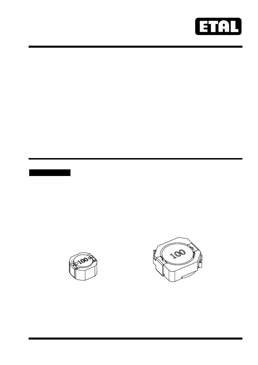
Components are available in two mechanical sizes,
suited to low-profile applications.
The larger 1003 size has lower DCR and higher
current rating.

The family provides reliable self-leaded Pb-free
terminations suitable for Pb-free and
conventional placement and reflow.


P7602-0603

P7602-1003

pa/etal/P7602-html.html
background image

P7602

ETALDOC 831/2

Page 2 of 3

August 2003

SPECIFICATIONS

Electrical

Part Number

Inductance

(µH)

(1)

DCR (m

) Max

Rated Current

I

RMS 

(A)

(2)

I

sat 

(A)

(3)

Rated DC

Current I

DC 

(4)

P7602-0603-2R0M

2.0±20%

19

3.3

3.0

-

P7602-0603-2R7M

2.7±20%

22

3.1

2.7

-

P7602-0603-3R3M

3.3±20%

26

2.8

2.6

-

P7602-0603-4R7M

4.7±20%

32

2.5

2.1

-

P7602-0603-6R2M

6.2±20%

35

2.4

1.8

-

P7602-0603-8R2M

8.2±20%

44

2.1

1.5

-

P7602-0603-100M

10±20%

50

2.0

1.5

-

P7602-0603-120M

12±20%

62

1.7

1.3

-

P7602-0603-150M

15±20%

77

1.5

1.1

-

P7602-0603-180M

18±20%

82

1.5

1.0

-

P7602-0603-220M

22±20%

106

1.3

0.97

-

P7602-0603-270M

27±20%

140

1.1

0.82

-

P7602-0603-330M

33±20%

162

1.0

0.76

-

P7602-0603-390M

39±20%

192

0.96

0.70

-

P7602-0603-470M

47±20%

209

0.89

0.68

-

P7602-0603-560M

56±20%

257

0.80

0.60

-

P7602-0603-680M

68±20%

320

0.71

0.56

-

P7602-0603-820M

82±20%

420

0.61

0.47

-

P7602-0603-101M

100±20%

477

0.57

0.45

-

P7602-0603-151M

150±20%

664

0.48

0.37

-

P7602-1003-1R5Y

1.5±30%

8.1

-

-

10

P7602-1003-2R5Y

2.5±30%

10

-

-

7.5

P7602-1003-3R8Y

3.8±30%

13

-

-

6

P7602-1003-5R2Y

5.2±30%

22

-

-

5.5

P7602-1003-7R0Y

7.0±30%

27

-

-

4.8

P7602-1003-100Y

10±30%

35

-

-

4.4

P7602-1003-150Y

15±30%

50

-

-

3.6

P7602-1003-220Y

22±30%

73

-

-

2.9

P7602-1003-330Y

33±30%

93

-

-

2.3

P7602-1003-470Y

47±30%

128

-

-

2.1

P7602-1003-680Y

68±30%

213

-

-

1.5

P7602-1003-101Y

100±30%

304

-

-

1.35

P7602-1003-151Y

150±30%

506

-

-

1.15

P7602-1003-221Y

220±30%

756

-

-

0.92

P7602-1003-331Y

330±30%

1090

-

-

0.70


Notes

1.  Inductance measured at 100kHz, 1V  (P7602-1003 100mV).
2.  Rated current, I

RMS

, is the current at which the temperature rise is 40ºC (max).

3.  Saturation current, I

sat

, is the DC current at which the zero-current inductance drops by 30% (typ).

4.  Rated DC Current, I

DC

, is the DC current at which the temperature rise is 30ºC, or the zero-current

inductance drops by 35%, whichever current is less.

5.  Operating temperature -25ºC to +105ºC.
6.  For non-standard inductance values, please contact Profec.

pa/etal/P7602-html.html
background image

P7602

ETALDOC 831/2

Page 3 of 3

August 2003

CONSTRUCTION


Dimensions shown are in millimetres

Terminal plating is pure tin (Sn).

Recommended reflow solder profile: 2 minutes (min) @ 100-150ºC, 10 seconds (max) @ 230ºC; time above

200ºC 30 seconds maximum.

ORDERING CODE

ABSOLUTE MAXIMUM RATINGS

Storage temperature

-40ºC to
+125ºC

Operating temperature

-25ºC to
+105ºC

P7601-

ÿÿÿð

-

ðððð

T

Tape and Reel

Tolerance
  M = ±20% (0603)
  Y = ±30% (1003)

Inductance code

Size (0603 or 1003)

Type code

Soldering temperature profile peak

260ºC 10s

T R A N S F O R M I N G    T H E    F U T U R E

Profec Technologies Ltd., 10 Betts Avenue, Martlesham Heath, Ipswich, IP5 3RH, England

                           Telephone: +44 (0) 1473 611422

Fax:  +44 (0) 1473 611919

Website: www.profec.com 

Email:  info@profec.co.uk,  sales@profec.com

FM 25326

ISO 9001

Fig. 2

P7602-1003  dimensions

10.4 max

10.

3 m

a

x

4.

0

max

7.3

1.6

3.

2

1.2

typ

ty

p

3.

0

MARKING

INDUCTANCE CODE

PCB PATTERN

Fig. 1

P7602-0603  dimensions

6.4 max

6.

3 m

a

x

3.

5

max

4.6

1.0

2.

6

 2.

0

ty

p

0.6

typ

MARKING

INDUCTANCE CODE

PCB PATTERN