ETALDOC 836/1
Page 1 of 4
September 2003
PRODUCT DATA SHEET
ULTRA LOW PROFILE
P7606
Family
POWER INDUCTOR
Features
Applications
∗
Current handling (Saturation to 2A)
∗
PC Cards
∗
Ultra Low profile (to 1mm)
∗
Electroluminescent displays
∗
Surface Mount
∗
LCD drivers
∗
Robust construction
∗
Hybrids
∗
Flat top for pick & place
∗
Daughter boards
∗
Pb-free
∗
Portable equipment
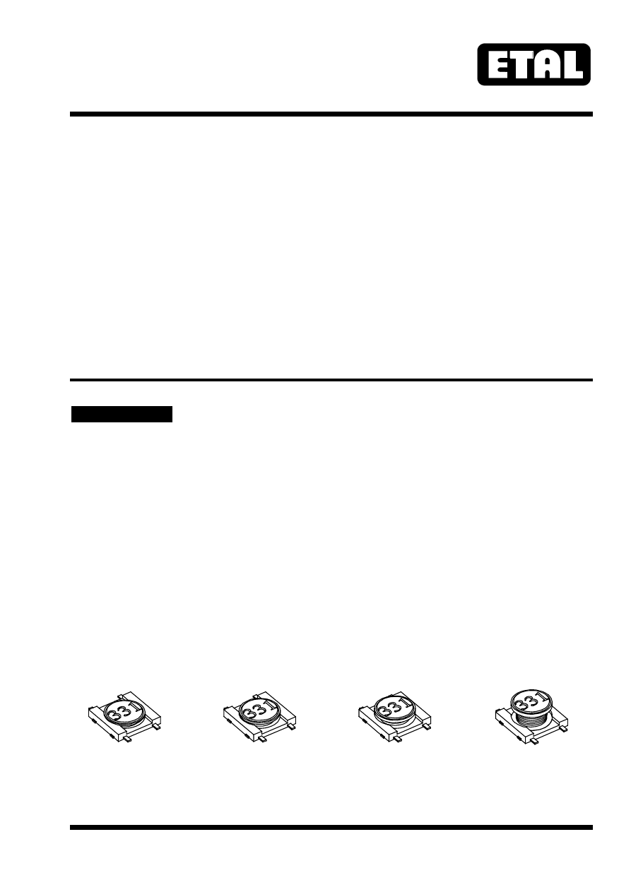
DESCRIPTION
The P7606 family comprises very low profile
inductors for height constrained applications.
Four sizes are available using the same PCB
footprint but varying in height from 1.0 to 2.5mm.
Despite their small size, these inductors are
capable of being used in genuine power
applications with saturation currents up to 2A.
The family covers inductance over a wide range
from 2.2µH to 3300µH.
The parts are mechanically robust and are
supplied with Pb-free terminations suitable for
Pb-free and conventional placement and reflow.
P7606-5210
P7606-5212
P7606-5215
P7606-5225