ETALDOC 588/9
Page 1 of 4
December 2003
PRODUCT DATA SHEET
MICROPROFILE SMD
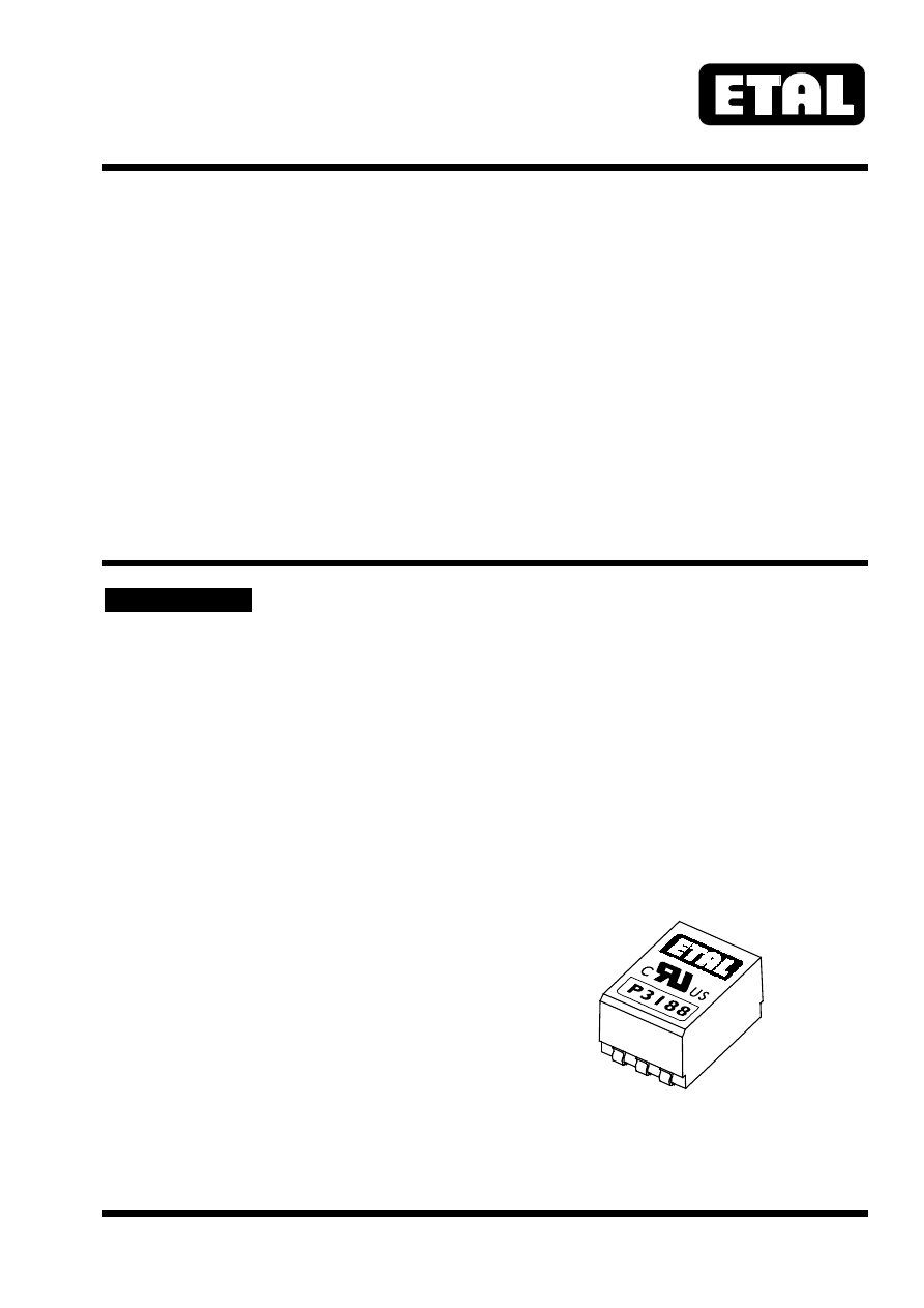
P3188
LINE MATCHING TRANSFORMER
Features
Applications
∗
Surface Mount
∗
Telecommunications
∗
Lead-free (Pb-free )
∗
V.22bis modems
∗
7mm seated height
∗
Voice
∗
Vacuum encapsulated
∗
Instrumentation
∗
IEC 60950 and UL 60950 certified
∗
UL Recognized Component
∗
Matches directly to 600
Ω
lines
DESCRIPTION
P3188 is a microprofile transformer for applications
where high performance and safety isolation to
international standards are required in an extremely
small case size.
Designed specifically as a surface mount device, the
P3188 features a 7mm seated height and is vacuum
encapsulated and tested to 6500VDC. The part is
completely lead-free and suitable for lead-free and
conventional placement and reflow.
P3188 offers fully reinforced insulation, is ideal for
voice telecommunications and low speed data
communications whilst capable of being matched to
both 600
Ω
and complex impedance telephone lines.
600
Ω
telephone lines are matched directly by
P3188 without external compensation
components.
In instrumentation applications, the P3188 can
provide wideband frequency response from 50Hz
to 50kHz.
P3188 is certified to IEC 60950 and UL 60950.
P3188 is a UL Recognized Component, and is
supported by an IEC CB Test Certificate.