ETALDOC 590/8
Page 1 of 4
December 2003
PRODUCT DATA SHEET
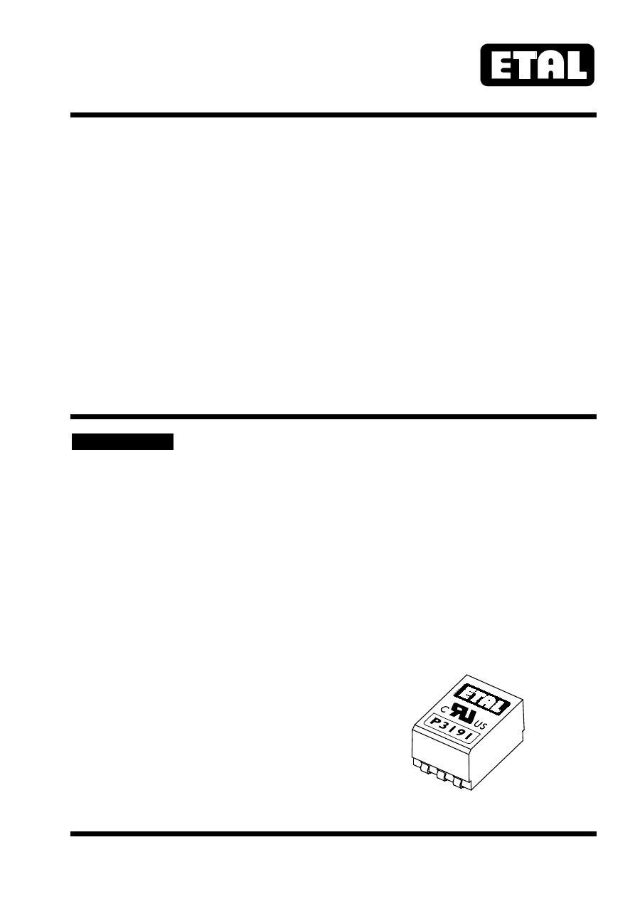
MICROPROFILE SMD
P3191
LINE MATCHING TRANSFORMER
Features
Applications
∗
Surface Mount
∗
Telecommunications
∗
Lead-free (Pb-free)
∗
V.34 modems
∗
7mm seated height
∗
Portable computers
∗
Vacuum encapsulated
∗
Fax/Modems
∗
IEC 60950 and UL 60950 certified
∗
UL Recognized Component
∗
Simple 600
Ω
match
DESCRIPTION
P3191 is a low distortion microprofile transformer
for applications where high performance and safety
isolation to international standards are required in an
extremely small case size.
Designed specifically as a surface mount device, the
P3191 features a 7mm seated height and is offered
in the same package as the now familiar P2781.
The part is completely lead-free and suitable for
lead-free and conventional placement and reflow.
Despite the subminiature size, the performance is
superior to that of much larger components. The
P3191 offers reinforced insulation, is ideal for data
communications at high data rates whilst capable of
being matched to both 600
Ω
and complex
impedance telephone lines.
When used with 600
Ω
lines no external
compensation components are required.
At moderate transmit power levels (e.g. -10dBm)
performance to 33,600 bits/second may be
achieved.
P3191 is certified to IEC 60950 and UL 60950.
P3191 is a UL Recognized Component, and is
supported an IEC CB Test Certificate.