background image

34

01-04

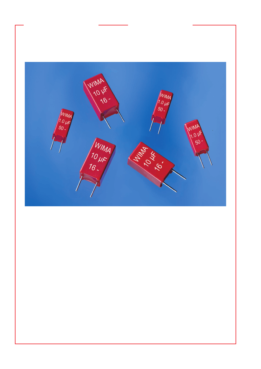
Mit den Werten WIMA MKS 02/1,0 

m

F im Subminiatur-Rastermaß 

2,5 mm und WIMA MKS 2/10 

m

F im Rastermaß 5 mm mit Abmes-

sungen von 5,5 x 10 x 4,6 bzw. 8,5 x 14 x 7,2 (B x H x L in mm)
setzt WIMA neue Maßstäbe in der Miniaturisierung bedrahteter 
Polyesterkondensatoren. Es stehen nun Kapazitätswerte zur Ver-
fügung, die bisher nur in erheblich größeren Bauformen realisiert 
werden konnten - so hat ein herkömmlicher MKT-Kondensator mit 
einem C-Wert von 10 

m

F/63 V- ein Rastermaß von 22,5 mm.

Die Kondensatoren weisen aufgrund der vollkontaktierten Elek-
troden und des geringen Längenmaßes eine sehr niedrige Eigen-
induktivität auf und eignen sich für alle Standardanwendungen 
wie Koppeln, Entkoppeln und Abblocken bis in den Bereich hoher 
Frequenzen. Mit den hohen Kapazitätswerten eröffnen sich
Anwendungsbereiche, die bisher anderen Technologien vobehal-
ten waren. Im Gegensatz zu beispielsweise Tantal-Elektrolytkon-
densatoren bieten die ungepolten Kunststofffolien-Kondensatoren 
eine hohe Stabilität der einzelnen Parameter in Abhängigkeit von
Frequenz und Temperatur sowie einen hohen Isolationswiderstand.

WIMA Miniaturkondensatoren sind in metallisierter Ausführung 
sowie in Film/Folien-Technik lieferbar. Das Kapazitätsspektrum 
reicht von 27 pF bis 10 

m

F mit Nennspannungen von 16 V- bis 

1000 V-. Alle Kondensatoren sind radial gegurtet lieferbar.

WIMA has set new standards in the miniaturization of wired 
polyester capacitors. With the values WIMA MKS 02/1.0 

m

with a sub-miniature PCM of 2.5 mm and WIMA MKS 2/10 

m

with a PCM of 5 mm and sizes 5.5 x 10 x 4.6 and 8.5 x 14 x 7.2
(W x H x L in mm), capacitance values are now available
which, up to now, could only be realized in considerably larger 
box sizes - a conventional MKT capacitor, for example, with a
C-rating of 10 

m

F/63 VDC has a PCM of 22.5 mm.

Due to their fully contacted electrodes and their short length,
the capacitors have very low self-inductance and are suitable
for all standard applications such as coupling, decoupling and
blocking even at high frequencies. The high capacitance ratings 
have opened up fields of application which have, so far, been
restricted to other technologies. As opposed to tantalum electro-
lytic capacitors, for example, non-polarized plastic film capac-
itors offer high stability of the individual parameters in relation
to frequency and temperature as well as high insulation resi-
stance.

WIMA miniature capacitors are available in metallized and film/
foil versions. The capacitance spectrum ranges from 27 pF to
10 

m

F with rated voltages from 16 VDC to 1000 VDC. All capaci-

tors are available taped and reeled. 

Hohe Kapazitäten
in kleinen Bauformen

High capacitances 
in small box sizes

pa/wima/wima_pcm25_capacitors-html.html
background image

35

01-04

    WIMA MKS 02

Metallisierte Polyester-Kondensatoren
im Subminiatur-Rastermaß 2,5 mm

˜

 Hervorragend zur Entkopplung bis in den Bereich

hoher Frequenzen geeignet.  

˜

 RM 2,5 Technologie

mit niedriger Eigeninduktivität für alle dämpfungs-
armen  Anwendungen.   

˜

  Günstiges  C/V  Produkt, 

hohe Volumenkapazität.

Metallized polyester capacitors 
in PCM 2.5 mm

˜

 Ideally suited for decoupling up to high-frequen-

cy ranges. 

˜

 PCM 2.5 mm technology with low self-

inductance  for  low  damping  applications.   

˜

  Very 

advantageous volume/capacitance ratio.

Technische Angaben

Dielektrikum:

 Polyäthylenterephthalat-Folie.

Beläge:

 Aluminium, aufmetallisiert.

Umhüllung:

 Flammhemmendes Kunststoffgehäuse, UL 94 V–0. 

Farbe: Rot. Aufdruck: Silber. Epoxidharzverguß: Rot.

Temperaturbereich:

 –55

)

 C bis +100

)

 C.

Prüfungen: 

Nach IEC 60384-2 bzw. EN 130 400.

Prüfklasse:

 55/100/21 nach IEC.

Isolationswerte

 bei +20° C:


U

N

        U

meß

          C 

 0,33 

m

F         0,33 

m

F < C 

 1,0 

m

F


    50 V- 

  10 V


 3,75 

 10

3

 M


1250 s (M

V


m

F) 


       Mittelwert: 1 

 10

4

 M

Mittelwert: 3000 s

      63 V-    50 V      

 3,75 

 10

3

 M


1250 s (M

V


m

F)


       Mittelwert: 1 

 10

4

 M

Mittelwert: 3000 s


100 V- 

100 V


 1 

 10

4

 M

-


       Mittelwert: 2 

 10

4

 M

V

Nach IEC 60384-2 und EN 130 400.
Meßzeit: 1 min.

Kapazitätstoleranzen:


±

 20 %, 

±

 10 %,

(

±

 5 % auf Anfrage).

Impulsbelastung:


C-Wert 

Flankensteilheit V/

m

s


pF/

m

max. Betrieb 

Prüfung

  1000  . . . 2200 

100 

1000

  3300  . . . 6800 

100 

1000

  0,01   . . . 0,022 

50 

500

  0,033 . . . 0,068 

30 

300

  0,1     . . . 0,33 

20 

200

  0,47   . . . 1,0 

15 

150

bei vollem Spannungshub.

Verlustfaktoren

 bei +20

)

 C: tan 

d


Gemessen bei 

 0,1 

m

0,1 

m

<

 C 

 1,0 

m

F


    1 kHz 

   8 

 10

-3


   8 

 10

-3


  10 kHz 

 15 

 10

-3


 15 

 10

-3


100 kHz 

 30 

 10

-3


Prüfspannung:

 1,6 U

N

 , 2 s.

Schwingen:

 6 h bei 10 . . . 2000 Hz und 0,75 mm Auslenkung

bzw. 10 g nach IEC 60068-2-6.

Unterdruck:

 1 kPa = 10 mbar nach IEC 60068-2-13.

Stoßtest:

 4000 Stöße mit 390 m/s

2

 nach IEC 60068-2-29.

Spannungsderating:

 Die zulässige Spannung vermindert sich 

gegenüber der Nennspannung bei Gleichspannungsbetrieb ab 
+85

)

 C, bei Wechselspannungsbetrieb ab +75

)

 C um 1,25 % 

je 1 K.
Kurven siehe Seite 6.

Technical Data

Dielectric:

 Polyethylene-terephthalate film.

Capacitor electrodes:

 Vacuum-deposited aluminium.

Encapsulation:

 Flame retardent plastic case, UL 94 V–0. 

Colour: Red. Marking: Silver. Epoxy resin seal: Red.

Temperature range:

 –55

)

 C to +100

)

 C.

Test specification: 

In accord. with IEC 60384-2 and EN 130 400.

Test category:

 55/100/21 in accordance with IEC.

Insulation resistance

 at +20° C:


U

r


U

test


 0.33 

m

0.33 

m

F < C 

 1.0 

m

F


  50 VDC    10 V


 3.75 x 10

3

 M


1250 sec (M

V

 x 

m

F) 


Mean value: 1 x10

4

 M

Mean value: 3000 sec

   63 VDC    50 V 

 3.75 x 10

3

 M


1250 sec (M

V

 x 

m

F)


Mean value: 1 x10

4

 M

Mean value: 3000 sec


100 VDC  100 V


 1 x 10

4

 M

-


Mean value: 2 x10

4

 M

V

In accordance with IEC 60384-2 and EN 130 400. 
Measuring time: 1 min.

Capacitance tolerances:


±

 20 %, 

±

 10 %, (

±

 5 % available 

subject to special enquiry).

Maximum pulse rise time:

  Capacitance 

Pulse rise time V/

m

sec


pF/

m

max. operation 

test

  1000  . . . 2200 

100 

1000

  3300  . . . 6800 

100 

1000

  0.01   . . . 0.022 

50 

500

  0.033 . . . 0.068 

30 

300

  0.1     . . . 0.33 

20 

200

  0.47   . . . 1.0 

15 

150

for pulses equal to the rated voltage.

Dissipation factors

 at +20

)

 C: tan 

d


at f 

 0.1 

m

0.1 

m

<

 C 

 1.0 

m

F


    1 kHz 

   8 x 10

-3


   8 x 10

-3


  10 kHz 

 15 x 10

-3


 15 x 10

-3


100 kHz 

 30 x 10

-3


Test voltage:

 1.6 U

r

 , 2 sec.

Vibration:

 6 hours at 10 . . . 2000 Hz and 0.75 mm displacement 

amplitude or 10 g in accordance with IEC 60068-2-6.

Low air density:

 1 kPa = 10 mbar in accordance with IEC 

60068-2-13.

Bump test:

 4000 bumps at 390 m/sec

2

 in accord. with IEC 60068-2-29.

Voltage derating:

 A voltage derating factor of 1.25 % per K 

must be applied from +85° C for DC voltages and from +75 ° C
for AC voltages.
Graphs see page 6.

pa/wima/wima_pcm25_capacitors-html.html
background image

36

01-04

0.1

1

10

100

f/MHz

3     5   7

3     5   7

7
5
3

7
5

3

10

1

0.1

0.01

Z

S

-- 1000 pF

-- 2200 pF

-- 4700 pF

-- 0.

01  µF

-- 0.

022 µF

-- 0.

047 µF

-- 0

.1     µ

F

-- 0.

22   µF

-- 0.

47   µF

-- 1.

0     µF

Scheinwiderstand in Abhängigkeit von 
der Frequenz (Richtwerte).

Impedance change with frequency
(general guide).

2.5

RM/PCM

am Drahtaustritt/

at the lead exit points

( 0.5)

L

W

H

d

6

-2

WIMA MKS 02

Werteübersicht / General Data


Kapazität 

50 VDC/30 VAC * 

63 VDC/40 VAC * 

100 VDC/63 VAC *


Capacitance 

PCM** 

PCM** 

PCM**


1000   pF 

2.5 

5.5 

4.6 

2.5


2.5 

4.6 

2.5


2.5 

4.6 

2.5


1500   „ 

2.5 

5.5 

4.6 

2.5


2.5 

4.6 

2.5


2.5 

4.6 

2.5


2200   „ 

2.5 

5.5 

4.6 

2.5


2.5 

4.6 

2.5


2.5 

4.6 

2.5


3300   „ 

2.5 

5.5 

4.6 

2.5


2.5 

4.6 

2.5


2.5 

4.6 

2.5


4700   „ 

2.5 

5.5 

4.6 

2.5


2.5 

4.6 

2.5


2.5 

4.6 

2.5


6800   „ 

2.5 

5.5 

4.6 

2.5


2.5 

4.6 

2.5


2.5 

4.6 

2.5


0.01   

m

2.5 

5.5 

4.6 

2.5


2.5 

4.6 

2.5 

2.5 

4.6 

2.5


0.015 „ 

2.5 

5.5 

4.6 

2.5 

2.5 

4.6 

2.5 

2.5 

4.6 

2.5


0.022 „ 

2.5 

5.5 

4.6 

2.5 

2.5 

4.6 

2.5 

2.5 

4.6 

2.5


0.033 „ 

2.5 

5.5 

4.6 

2.5 

2.5 

4.6 

2.5 

2.5 

4.6 

2.5


0.047 „ 

2.5 

5.5 

4.6 

2.5 

2.5 

4.6 

2.5 

2.5 

4.6 

2.5


0.068 „ 

2.5 

5.5 

4.6 

2.5 

7.5 

4.6 

2.5 

7.5 

4.6 

2.5


0.1     

m

2.5 

5.5 

4.6 

2.5 

7.5 

4.6 

2.5 

7.5 

4.6 

2.5


0.15   „ 

7.5 

4.6 

2.5 

7.5 

4.6 

2.5 

3.8 

8.5 

4.6 

2.5


0.22   „ 

7.5 

4.6 

2.5 

7.5 

4.6 

2.5 

4.6 

4.6 

2.5


0.33   „ 

3.8 

8.5 

4.6 

2.5 

3.8 

8.5 

4.6 

2.5 

5.5 

10 

4.6 

2.5


0.47   „ 

4.6 

4.6 

2.5 

4.6 

4.6 

2.5


0.68   „ 

4.6 

4.6 

2.5 

5.5 

10 

4.6 

2.5


1.0     

m

5.5 

10 

4.6 

2.5

*

 Wechselspannungen: f = 50 Hz; 1,4 

 U

eff


Z

 + U– 

 U

N

*

 AC voltage: f = 50 Hz, 1.4 x U

rms

 + UDC 

 U

r


Neue Werte / New values

** PCM = Printed circuit module = Rastermaß.
** PCM = Printed circuit module = lead spacing.

Gegurtete Ausführung siehe Seite 93.
Taped version see page 93.

Alle Maße in mm.
Dims. in mm.

d = 0.4 

Ø

Abweichungen und Konstruktionsänderungen vorbehalten.
Rights reserved to amend design data without prior notification.

pa/wima/wima_pcm25_capacitors-html.html
background image

14

01-04

P

P

1

P

0

P

2

F

d

P

P

1

H

1

H

P

0

d

P

2

F

t

D

0

W

2

)

h

W

0

P

1

P

2

P

0

P

H

1

H

W

1

W

d

F

Diagram 1:

PCM 2.5/5/7.5mm

Diagram 3: PCM 22.5 and 27.5*mm

*PCM 27.5 taping possible with two feed holes between components

Diagram 2: PCM 10/15 mm


Dimensions for radial taping

  Designation 

Symbol 

PCM 2.5 taping 

PCM 5 taping 

PCM 7.5 taping 

PCM 10 taping

*


PCM 15 taping

*


PCM 22.5 taping 

PCM 27.5 taping

  Carrier tape width 

18.0 

p

0.5


18.0 

p

0.5


18.0 

p

0.5


18.0 

p

0.5


18.0 

p

0.5


18.0 

p

0.5


18.0 

p

0.5


Hold-down tape width 

W

0


6.0

 for hot-sealing 

6.0

 for hot-sealing 

12.0

 for hot-sealing 

12.0

 for hot-sealing 

12.0

 for hot-sealing 

12.0

 for hot-sealing 

12.0

 for hot-sealing


       adhesive tape 

       adhesive tape 

         adhesive tape 

         adhesive tape 

         adhesive tape 

         adhesive tape 

         adhesive tape

  Hole position 

W

1


9.0 

p

0.5


9.0 

p

0.5


9.0 

p

0.5


9.0 

p

0.5


9.0 

p

0.5


9.0 

p

0.5


9.0 

p

0.5

  Hold down tape position 

W

2


0.5 to 3.0 max. 

0.5 to 3.0 max. 

0.5 to 3.0 max. 

0.5 to 3.0 max. 

0.5 to 3.0 max. 

0.5 to 3.0 max. 

0.5 to 3.0 max.

  Feed hole diameter 

D

0


4.0 

p

0.2


4.0 

p

0.2


4.0 

p

0.2


4.0 

p

0.2


4.0 

p

0.2


4.0 

p

0.2


4.0 

p

0.2

  Pitch of component 

12.7 

p

1.0


12.7 

p

1.0


12.7 

p

1.0


25.4 

p

1.0


25.4 

p

1.0


38.1 

p

1.5


3*8.1 

p

1.5

 or 50.8 

p

1.5


cumulative pitch 


cumulative pitch 


cumulative pitch 


cumulative pitch 


cumulative pitch 


cumulative pitch 


cumulative pitch

  Feed hole pitch 

P

0


12.7 

p

0.3   error max. 

12.7 

p

0.3   error max. 

12.7 

p

0.3   error max. 

12.7 

p

0.3   error max. 

12.7 

p

0.3   error max. 

12.7 

p

0.3   error max. 

12.7 

p

0.3   error max.


1.0 mm/20 pitch 


1.0 mm/20 pitch 


1.0 mm/20 pitch 


1.0 mm/20 pitch 


1.0 mm/20 pitch 


1.0 mm/20 pitch 


1.0 mm/20 pitch

  Feed hole centre 

P

1


5.1 

p

0.5


3.85 

p

0.7


2.6 

p

0.7


7.7 

p

0.7


5.2 

p

0.7


7.8 

p

0.7


5.3 

p

0.7

  to lead 

  Hole centre to 

P

2


6.35 

p

1.3


6.35 

p

1.3


6.35 

p

1.3


12.7 

p

1.3


12.7 

p

1.3


19.05 

p

1.3


19.05 

p

1.3

  component centre 

  Feed hole centre to bottom 

v


16.5 

p

0.3


16.5 

p

0.3


16.5 

p

0.5


16.5 

p

0.5


16.5 

p

0.5


16.5 

p

0.5


16.5 

p

0.5

  edge of the component 


18.5 

p

0.5


18.5 

p

0.5


18.5 

p

0.5


18.5 

p

0.5


18.5 

p

0.5


18.5 

p

0.5


18.5 

p

0.5

  Feed hole centre to top 

H

1


H+H

component

 < H

1


H+H

component

 < H

1


H+H

component

 < H

1


H+H

component

 < H

1


H+H

component

 < H

1


H+H

component

 < H

1


H+H

component

 < H

1

  edge of component 


32.25 max. 

32.25 max. 

24.5 to 31.5 

25.0 to 31.5 

26.0 to 37.0 

30.0 to 43.0 

35.0 to 45.0

  Lead spacing at 

2.5 

p

0.5


5.0 

+0.8


7.5 

p

0.8


10.0 

p

0.8


15 

p

0.8


22.5 

p

0.8


27.5 

p

0.8

  upper edge of carrier tape 


–0.2

  Lead diameter 

0.4 

p

0.05


0.5 

p

0.05


„ 

0.5 

p

0.05


or

 0.7 

–0.05


„ 

0.5 

p

0.05


or

 0.7 

–0.05


0.8 

–0.05


0.8 

–0.05


„ 

0.8 

–0.05


or

 1.0 

–0.05

  Component alignment 

D

p

 2.0 max. 

p

 2.0 max. 

p

 3.0 max. 

p

 3.0 max. 

p

 3.0 max. 

p

 3.0 max. 

p

 3.0 max.

  Total tape thickness 

0.7 

p

0.2


0.7 

p

0.2


0.7 

p

0.2


0.7 

p

0.2


0.7 

p

0.2


0.7 

p

0.2


0.7 

p

0.2


ROLL/AMMO 


AMMO


Package


v


(see also page 15)

  Unit 


see details page 93.


v

  Please give „H“ dimensions and desired packaging type when ordering. 

Dims in mm.


„ 

  Diameter of leads see General Data. 

Please clarify customer-specific deviations with the manufacturer.


*

  PCM 10 and PCM 15 can be crimped to PCM 7.5.

    Position of components according to PCM 7.5 (sketch 1). P

0

 = 12.7 or 15.0 is possible.


+0.07 

+0.07 

+0.08 

+0.08 

+0.08 

+0.1

  REEL


P

 360 max.


B


52 

p

2       depending on


P

 30 

p

  58 

p

2       comp. dimensions


  52 

p


  54 

p

2      depending


REEL 

P

 360 max.


B  58 

p

2


or

 REEL 

P

 500 max.


B  60 

p

2      on PCM and


P

 30 

p

1


  66 

p

P

 25 

p

1


  68 

p

2      component dimensions

Typical dimensions
for taping configuration

pa/wima/wima_pcm25_capacitors-html.html
background image

15

01-04

BAR CODE

Etikettierung der Verpackungs- 

BAR CODE „Code 39“ 

Labelling of package units in 

einheiten klartextlich und mit  


plain text and with 

alphanumerischem Strichcode 


alphanumerical Bar Code

Scanner-Decodierung von 


Scanner decoding of 

  WIMA-Lieferernummer 


  WIMA supplier number

  Kunden-Bestellnummer 


  Customer‘s P/O number

  Kunden-Sachnummer 


  Customer‘s part number

  WIMA-Bezeichnung 


  WIMA description

  – Artikel 


  – article

  – Kapazitätswert 


  – capacitance value

  – Kapazitätstoleranz 


  – capacitance tolerance

  – Nennspannung 


  – rated voltage

  – Abmessungen 


  – dimensions

  WIMA-Kommissionsnummer 


  WIMA acknowledgement 

  Stückzahl 


  number


  Quantity

Zusätzlich in Klartext Liefer-
datum und Kundenname 


In addition date of delivery and 


customer‘s name in plain text


Made in Germany


WIMA

 Kondensatoren/Capacitors 

Werk Aurich


26.01.04-30/31

 
  Lieferer-Nr. / Supplier No. (V): . . .

 
  Bestell-Nr. / P/O No.: . . .

  MKS-4 (1P)  2.2 

m

F  20 %  100 V–   8 x 15 x 18  RM 15


  Komm-Nr. / Internal P/O No.: . . .

  Sach-Nr. / Part No. (P): . . .

  Menge / Quant. (Q): . . .        Kunde / Customer: . . . 

26.01.04-30/31

Types of tape packaging of 
capacitors for automatic 
radial insertion

Gurt-Verpackungsarten für 
Kondensatoren mit radialen 
Anschlüssen

˜

  Rollenverpackung ROLL 

˜

  Lagenverpackung AMMO 

˜

  Trommelverpackung REEL

  ROLL packaging 

  AMMO packaging 

  REEL packaging

ciebadebadebaeagjebadebacj

ciebadebadebaeagjebadebaddebaeebeaadebaaged

ciebadebadebaeagjebadebacj

ciebadebadebaeagjebadebadebaiebadebadebaeiebadebadebaeiebadebadebaeebadebadebaiebadebdebaeaedi

ciebadebadebaeagjebadebadebaadebaeebadebadebaiebadebadebaea

baeagjebadebdebbaiaea

340 m

ax.

340 m

ax

.

50 max.

50 max.

70 max.

340

 ma

x.

490

 ma

x.

340 m

ax

.

370 m

ax

.

.

30 1

25 1

360 m

ax

.

500 m

ax

.

B

WIMA 

Kondensatoren

MKS-4 

Capacitors

2.2 

m

F  20%  100 V–

8 x 15 x 18  RM 15

pa/wima/wima_pcm25_capacitors-html.html
background image

92

01-04

Mindeststückzahlen
für Schüttware und EPS*

Minimum packing quantities
for bulk capacitors and TPS*


Rastermaß/PCM

    Bauform/Box size 

Stückzahl lose 

Stückzahl/EPS* 

MOQ

*


pcs. per packaging unit bulk  pcs. per packaging unit/TPS*


  2.5 

  5.5 

  4.6 

1000 

– 

5000


  2.5 

  7 

  4.6 

1000 

– 

5000


  3 

  7.5 

  4.6 

1000 

– 

5000


2.5 mm


  3.8 

  8.5 

  4.6 

1000 

– 

5000


  4.6 

  9 

  4.6 

1000 

– 

5000


  5.5 

10 

  4.6 

1000 

– 

5000


  2.5 

  5.5 

  7.2 

1000 

– 

5000


  2.5 

  6.5 

  7.2 

1000 

– 

5000


  3 

  7.5 

  7.2 

1000 

– 

5000


  3.5 

  8.5 

  7.2 

1000 

– 

5000


  4.5 

  6 

  7.2 

  500 

– 

5000


  4.5 

  8.5 

  7.2 

  500 

– 

5000


  4.5 

  9.5 

  7.2 

  500 

– 

5000


  5 

  9 

  7.2 

  500 

– 

5000


5 mm


  5 

10 

  7.2 

  500 

– 

5000


  5.5 

  7 

  7.2 

  500 

– 

5000


  5.5 

11.5 

  7.2 

  500 

– 

5000


  6.5 

  8 

  7.2 

  500 

– 

5000


  7.2 

  8.5 

  7.2 

  500 

– 

5000


  7.2 

13 

  7.2 

  500 

– 

5000


  8.5 

10 

  7.2 

  500 

– 

5000


  8.5 

14 

  7.2 

  500 

– 

5000


  2.5 

  7 

10 

1000 

– 

5000


  3 

  8.5 

10 

  500 

– 

5000


  4 

  9 

10 

  500 

– 

5000


7.5 mm


  4.5 

  9.5 

10.3 

  500 

– 

5000


  5 

10.5 

10.3 

  500 

– 

5000


  5.7 

12.5 

10.3 

  300 

– 

5000


  3 

  9 

13 

  500 

– 

2000


  4 

  8.5 

13.5 

1000 

– 

2000


  4 

  9 

13 

  300 

– 

2000


  4 

  9.5 

13 

  300 

– 

2000


10 mm


  5 

10 

13.5 

1000 

– 

2000


  5 

11 

13 

  250 

– 

2000


  6 

12 

13 

  200 

– 

2000


  6 

12.5 

13 

  200 

– 

2000


  4 

10 

18 

  250 

– 

2000


  5 

11 

18 

  200 

– 

2000


  5 

13 

19 

1000 

– 

2000


  6 

12.5 

18 

  250 

– 

2000


  6 

14 

19 

1000 

– 

2000


15 mm


  7 

14 

18 

  200 

– 

1000


  7 

15 

19 

1000 

– 

1000


  8 

15 

18 

  200 

– 

1000


  8 

17 

19 

  500 

– 

1000


  9 

16 

18 

  150 

– 

1000


10 

18 

19 

  500 

– 

1000


  5 

14 

26.5 

– 

180 

1000


  6 

15 

26.5 

– 

155 

1000


  7 

16.5 

26.5 

– 

130 

1000


  8 

20 

28 

– 

115 

1000


  8.5 

18.5 

26.5 

– 

110 

1000


22.5 mm


10 

22 

28 

– 

  90 

  500


10.5 

19 

26.5 

– 

  85 

  500


10.5 

20.5 

26.5 

– 

  85 

  500


11 

21 

26.5 

– 

  85 

  500


12 

24 

28 

– 

  75 

  500


  9 

19 

31.5 

– 

  80 

  500


11 

21 

31.5 

– 

  68 

  500


13 

24 

31.5 

– 

  56 

  500


13 

25 

33 

– 

  56 

  500


15 

26 

31.5 

– 

  48 

  500


27.5 mm


15 

26 

33 

– 

  48 

  500


17 

29 

31.5 

– 

  44 

  500


17 

34.5 

31.5 

– 

  44 

  500


20 

32 

33 

– 

  36 

  500


20 

39.5 

31.5 

– 

  36 

  500


  9 

19 

41.5 

– 

  60 

  500


11 

22 

41.5 

– 

  51 

  500


13 

24 

41.5 

– 

  42 

  500


15 

26 

41.5 

– 

  36 

  500


37.5 mm


17 

29 

41.5 

– 

  33 

  500


19 

32 

41.5 

– 

  27 

  500


20 

39.5 

41.5 

– 

  27 

  500


24 

45.5 

41.5 

– 

  21 

  500

  Änderungen vorbehalten / Rights reserved to amend design data. 

* Einstapel-Paletten-System / Tray-Packing-System

*

  MOQ = Minimum Order Quantity als ein Vielfaches einer Verpackungseinheit. Muster und Anlaufserien auf Anfrage.

*

  MOQ = Minimum Order Quantity as a multiple of one packing unit. Samples and pre-production needs on request.


pa/wima/wima_pcm25_capacitors-html.html
background image

93

01-04

Verpackungseinheiten für gegurtete
Kondensatoren mit radialen Anschlüssen

Packing units for taped
capacitors with radial leads


Rastermaß/PCM


 Bauform/Box size 

ROLL


REEL


AMMO 

MOQ

*


P

 360 

P

 500 

340 x 340  490 x 370


  2.5 

  5.5 

  4.6 

2200 

2500 

– 

2800 

– 

5000


  2.5 

  7 

  4.6 

2200 

2500 

– 

2800 

– 

5000


  3 

  7.5 

  4.6 

2000 

2300 

– 

2300 

– 

5000


2.5 mm


  3.8 

  8.5 

  4.6 

1500 

1800 

– 

1800 

– 

5000


  4.6 

  9 

  4.6 

1200 

1500 

– 

1500 

– 

5000


  5.5 

10 

  4.6 

  900 

1200 

– 

1200 

– 

5000


  2.5 

  5.5 

  7.2 

2200 

2500 

– 

2800 

– 

5000


  2.5 

  6.5 

  7.2 

2200 

2500 

– 

2800 

– 

5000


  3 

  7.5 

  7.2 

2000 

2300 

– 

2300 

– 

5000


  3.5 

  8.5 

  7.2 

1600 

2000 

– 

2000 

– 

5000


  4.5 

  6 

  7.2 

1300 

1500 

– 

1500 

– 

5000


  4.5 

  8.5 

  7.2 

1300 

1500 

– 

1500 

– 

5000


  4.5 

  9.5 

  7.2 

1300 

1500 

– 

1500 

– 

5000


  5 

  9 

  7.2 

1100 

1400 

– 

1400 

– 

5000


5 mm


  5 

10 

  7.2 

1100 

1400 

– 

1400 

– 

5000


  5.5 

  7 

  7.2 

1000 

1200 

– 

1200 

– 

5000


  5.5 

11.5 

  7.2 

1000 

1200 

– 

1200 

– 

5000


  6.5 

  8 

  7.2 

  800 

1000 

– 

1000 

– 

5000


  7.2 

  8.5 

  7.2 

  700 

1000 

– 

1000 

– 

5000


  7.2 

13 

  7.2 

  700 

  950 

– 

1000 

– 

5000


  8.5 

10 

  7.2 

  600 

  800 

– 

  800 

– 

5000


  8.5 

14 

  7.2 

  600 

  800 

– 

  800 

– 

5000


  2.5 

  7 

10 

– 

2500 

4400 

2500 

– 

5000


  3 

  8.5 

10 

– 

2200 

4300 

2300 

4150 

5000


  4 

  9 

10 

– 

1700 

3200 

1700 

3100 

5000


7.5 mm


  4.5 

  9.5 

10.3 

– 

1500 

2900 

1400 

2800 

5000


  5 

10.5 

10.3 

– 

1300 

2500 

1300 

– 

5000


  5.7 

12.5 

10.3 

– 

1000 

2200 

1100 

– 

5000


  3 

  9 

13 

– 

1100 

2200 

– 

1950 

2000


  4 

  8.5 

13.5 

– 

  900 

1600 

– 

1450 

2000


  4 

  9 

13 

– 

  900 

1600 

– 

1450 

2000


  4 

  9.5 

13 

– 

  900 

1600 

– 

1450 

2000


10 mm


  5 

10 

13.5 

– 

  700 

1300 

– 

1200 

2000


  5 

11 

13 

– 

  700 

1300 

– 

1200 

2000


  6 

12 

13 

– 

  550 

1100 

– 

1000 

2000


  6 

12.5 

13 

– 

  550 

1100 

– 

1000 

2000


  4 

10 

18 

– 

  700 

1600 

– 

1500 

2000


  5 

11 

18 

– 

  600 

1200 

– 

1150 

2000


  5 

13 

19 

– 

  600 

1200 

– 

1200 

2000


  6 

12.5 

18 

– 

  500 

1000 

– 

1000 

2000


  6 

14 

19 

– 

  500 

1000 

– 

1000 

2000


15 mm


  7 

14 

18 

– 

  450 

  900 

– 

  850 

1000


  7 

15 

19 

– 

  450 

  900 

– 

  850 

1000


  8 

15 

18 

– 

  400 

  800 

– 

  740 

1000


  8 

17 

19 

– 

  400 

  800 

– 

  740 

1000


  9 

16 

18 

– 

  350 

  700 

– 

  650 

1000


10 

18 

19 

– 

  300 

  650 

– 

  590 

1000


  5 

14 

26.5 

– 

– 

  800 

– 

  770 

1000


  6 

15 

26.5 

– 

– 

  700 

– 

  640 

1000


  7 

16.5 

26.5 

– 

– 

  600 

– 

  550 

1000


  8 

20 

28 

– 

– 

  500 

– 

  480 

1000


  8.5 

18.5 

26.5 

– 

– 

  480 

– 

  450 

1000


22.5 mm


10 

22 

28 

– 

– 

  420 

– 

  380 

  500


10.5 

19 

26.5 

– 

– 

  400 

– 

  360 

  500


10.5 

20.5 

26.5 

– 

– 

  400 

– 

  360 

  500


11 

21 

26.5 

– 

– 

  380 

– 

  350 

  500


12 

24 

28 

– 

– 

  350 

– 

  310 

  500


  9 

19 

31.5 

– 

– 

460/340* 

– 

  420 

  500


11 

21 

31.5 

– 

– 

380/280* 

– 

  350 

  500


27.5 mm


13 

24 

31.5 

– 

– 

  300 

– 

  290 

  500


15 

26 

31.5 

– 

– 

  270 

– 

  250 

  500

*  bei 2-Zoll-Transportschritt / for 2-inch transport pitches. 

Änderungen vorbehalten / Rights reserved to amend design data.

*

  MOQ = Minimum Order Quantity als ein Vielfaches einer Verpackungseinheit. Muster und Anlaufserien 1 Verpackungseinheit minimum.

*

  MOQ = Minimum Order Quantity as a multiple of one packing unit. Minimum 1 packing unit for samples and pre-production needs.