background image

84

01-04

Funk-Entstör-Kondensatoren dienen nicht nur zur Einhaltung
der EMV-Bestimmungen, sondern schützen darüber hinaus das
Gerät vor netzseitigen Überspannungen. Der Auswahl dieser
Bauelemente ist daher besondere Sorgfalt zu widmen.

˜ 

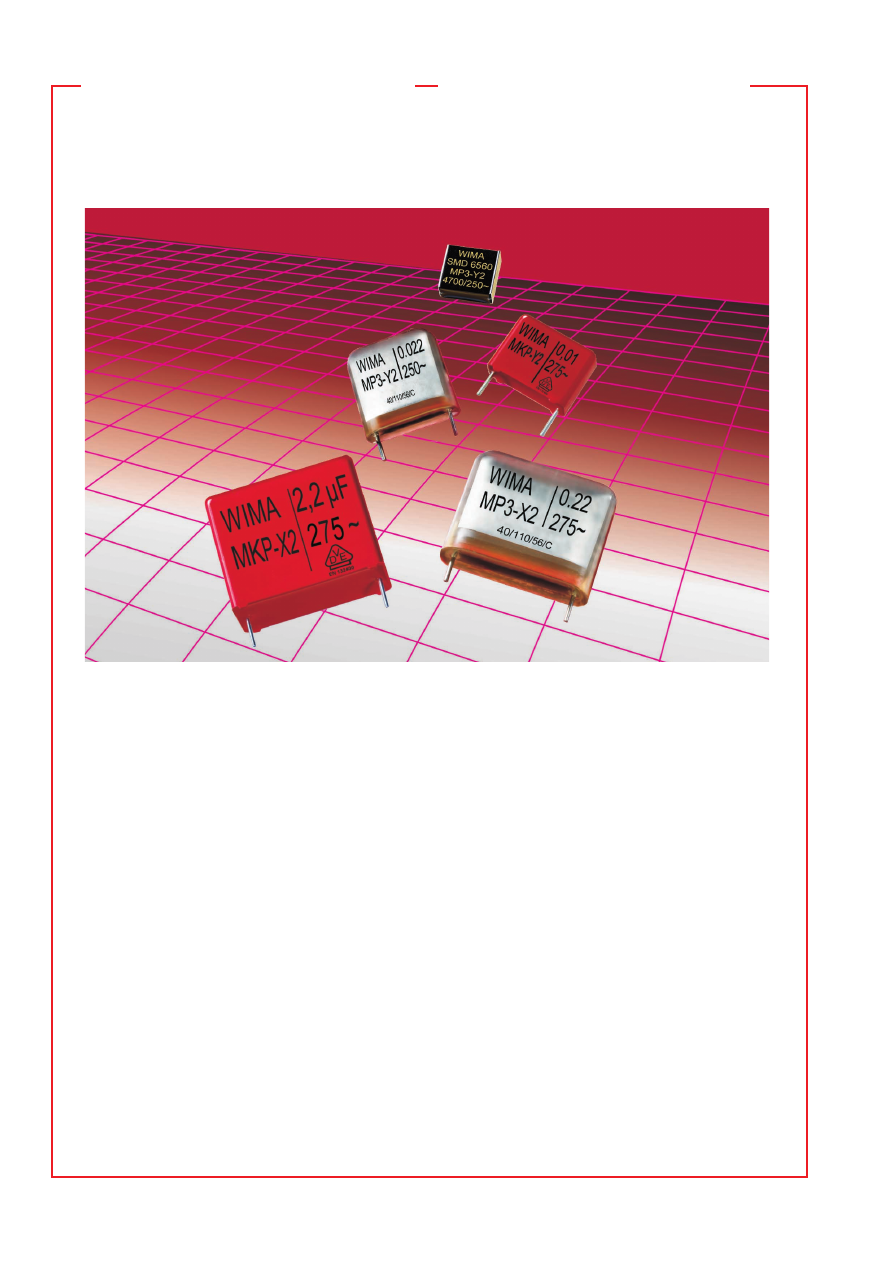
WIMA Polypropylen Funk-Entstör-Kondensatoren zeichnen

sich durch höhere Kapazitätswerte und kleinere Bauformen
im Vergleich zu Metallpapier-Kondensatoren aus. Sie sind
mit Kapazitäten bis 2,2 

m

F und Wechselspannungen von

275 V

Z


 und 300 V

Z


 in den Klassen X2 und Y2 erhältlich.

Aufgrund des verwendeten Dielektrikums besitzen sie ein
sehr günstiges Preis/Leistungsverhältnis.

˜ 

WIMA Metallpapier-Kondensatoren sind weder passiv

noch aktiv entflammbar. Die unter Vakuum harzimprägnier-
ten und mit selbstverlöschendem Gießharz umhüllten Bau-
teile heilen aufgrund der guten Oxidationsbilanz des Papier-
dielektrikums selbst bei energiereichen Impulsen hervor-
ragend aus. Die Kondensatoren sind für Temperaturen bis
+ 110 

o

C spezifiziert und stehen in den Klassen X2 und Y2

zur Verfügung.
Die spezifizierte Nennwechselspannung berücksichtigt
gemäß IEC 60384-14 ein Ansteigen der Netzspannung bis
10 % über dem Nennwert.

Radio interference suppression capacitors must not only satisfy
EMC requirements in suppressing outgoing interference from an
application but they must also protect the appliance from 
incoming power surges. Hence careful selection of these comp-
onents is essential.

˜ 

The special feature of WIMA polypropylene RFI capac-

itors are the high capacitance values at smaller case sizes 
compared to metallized paper capacitors, being available
up to 2.2 

m

F with AC voltages of 275 VAC and 300 VAC for

class X2 and Y2. Based on the dielectric used they are highly
cost-effective.

˜ 

WIMA metallized paper capacitors are neither actively nor

passively flammable. The components are resin impregnated
under vacuum and encapsulated with self-extinguishing cast
resin. Thanks to the good oxidation balance of the paper
dielectric, they have outstanding self-healing properties even
with high energy pulses. The capacitors are specified for
temperatures up to + 110 

o

C and are available for class X2

and Y2 applications.
The specified rated AC voltage takes into account a rise of
the mains voltage of up to 10 % above the nominal value, in
accordance with IEC 60384-14.

Radio interference
suppression capacitors for
overvoltage protection

Funk-Entstör-Kondensatoren
zum Schutz vor Über-
spannungen des Netzes

pa/wima/wima_rfi_capacitors-html.html
background image

27

01-04

 WIMA SMD MP 3-Y2

SMD Metallpapier-Funk-
Entstörkondensatoren Klasse Y2

˜

 Nach DIN EN 132 400 / IEC 60384-14/2 Klasse Y2.

˜

  Hoher  Entstörungsgrad  durch  dämpfungsarmen 

Aufbau mit niedrigem ESR.  

˜

 Hohe Sicherheit gegen

aktive und passive Entflammung. 

˜

 Ausgezeichnetes

Regenerierverhalten.

Metallized paper SMD RFI
capacitors class Y2

˜

  In  accordance  with  IEC  60384-14/2  class  Y2.

˜

  Good  attenuation  and  low  ESR  for  high  degree 

of  interference  suppression.   

˜

  Particularly  high 

reliability  against  active  and  passive  flammability. 

˜

 Problem-free clearing.

Technical Data

Dielectric:

 Paper, epoxy resin impregnated.

Capacitor electrodes:

 Vacuum-deposited.

Encapsulation:

 Flame retardent plastic case, UL 94 V–0, 

with epoxy resin seal. Colour: Black. Marking: Gold.

Temperature range:

 –40 

)

 C to +110 

)

 C.

Test specifications: 

In accordance with DIN EN 132 400.

Test category:

 40/110/56/C in accordance with IEC.

Insulation resistance

 at +20 ° C:

 12 x 10

3

 M

V

 in accordance with DIN EN 132 400

Measuring voltage: 100 V/1 min.

Capacitance tolerance:


±

 20 %.

Maximum pulse rise time:

  Capacitance 

Pulse rise time V/

m

sec


pF 

max. operation


1000 

1000


1500 

600

  2200 . . . 4700 

450

In accordance with DIN EN 132 400.

Dissipation factor:

 tan 

 13 x 10

-3

 at 1 kHz and +20 

)

 C.

Test voltage:

 2700 VDC

,

 2 sec.


SMD MP 3-Y2 Approvals


Country 

Authority 

Specification 

Approval No.


Germany 

VDE 

DIN EN 132 400 

87455


IEC 60384-14/2

Resistance to soldering heat:

Solder bath temperature max. 260 ° C.
Soldering duration max 5 sec.
Change in capacitance 

D

C/C < 3 %.

In accordance with DIN IEC 60068-2-20 (test Tb.).

Soldering process:

 Wave soldering and re-flow soldering

(see temperature/time graphs page 30).

Technische Angaben

Dielektrikum:

 Kondensatorpapier, imprägniert mit Epoxidharz.

Beläge:

 Aufmetallisiert.

Umhüllung:

 Flammhemmendes Kunststoffgehäuse. UL 94 V–0, 

Epoxidharzverguß. Farbe: Schwarz. Aufdruck: Gold.

Temperaturbereich:

 –40 

)

 C bis +110 

)

 C.

Prüfungen: 

Nach DIN EN 132 400.

Prüfklasse:

 40/110/56/C nach IEC.

Isolationswerte

 bei +20 ° C:

12 

 10

3

 M

V

 nach DIN EN 132 400. 

Meßspannung: 100 V/1 min.

Kapazitätstoleranz:


±

 20 %.

Impulsbelastung:


C-Wert 

Flankensteilheit V/

m

s


pF 

max. Betrieb


1000 

1000


1500 

600

  2200 . . . 4700 

450

Nach DIN EN 132 400.

Verlustfaktor:

 tan 

 13 

 10

-3

 bei 1 kHz und +20 

)

 C

Prüfspannung:

 2700 V-, 2 s.


Prüfzeichen SMD MP 3-Y2


Land 

Prüfstelle 

Norm 

Ausweis-Nr.

  Deutschland 

VDE 

DIN EN 132 400 

87455


IEC 60384-14/2

Lötwärmebeständigkeit:

Temperatur des Lötbades max. 260 ° C.
Lötdauer max. 5 s. Kapazitätsänderung 

D

C/C < 3 %.

Prüfung Tb nach DIN IEC 60068-2-20.

Löttechnik:

 Wellenlötung und Reflowlötung

(siehe Temperatur/Zeitdiagramm Seite 30).

pa/wima/wima_rfi_capacitors-html.html
background image

28

01-04

WIMA SMD MP 3-Y2

Werteübersicht / General Data


Kapazität


250 VAC *


Capacitance


Size Code


± 0.2 

± 0.3 

± 0.2


1000 pF 

16.5 

15.0 

7.0 

6560


1500 „ 

16.5 

15.0 

7.0 

6560


2200 „ 

16.5 

15.0 

7.0 

6560


3300 „ 

16.5 

15.0 

7.0 

6560


4700 „ 

16.5 

15.0 

7.0 

6560

* Wechselspannungen: f = 50 Hz.
* AC voltage: f = 50 Hz.

Auch Werte der E12-Reihe lieferbar.
Also available in E12-values.

Gegurtete Ausführung siehe Seite 29.
Taped version see page 29.

Alle Maße in mm. / Dims. in mm.

Lötpadempfehlung. / Solder pad recommendation.

Abweichungen und Konstruktionsänderungen vorbehalten. / Rights reserved to amend design data without prior notification.

H

W

L

0.7

0.7

6

15

2.5

Klebespalt

Bonding slit

--   1

000

 pF

--   1

500

 pF

--   2

200

 pF

--   3

300

 pF

--   4

700

 pF

1

10

100

1000

f/MHz

3     5  7

3     5  7

7
5

3

7
5

3

10

1

0.1

0.01

Z

S

Scheinwiderstand in Abhängigkeit von 
der Frequenz (Richtwerte).

Impedance change with frequency
(general guide).

Kapazitätsänderung
in Abhängigkeit
von der Temperatur
(f = 1 kHz))
(Richtwerte)

Capacitance change
with temperature
(f = 1 kHz)
(general guide)

Isolationswert
in Abhängigkeit
von der Temperatur
(Richtwerte)

Insulation
resistance change
with temperature
(general guide)

Verlustfaktor
in Abhängigkeit
von der Temperatur
(f = 1 kHz)
(Richtwerte)

Dissipation
factor change
with temperature
(f = 1 kHz)
(general guide)

-55   -40       -20         0         20        40        60        80      100

T(° C)

M x µF(s)

S

10

10

10

4

3

2

-55   -40       -20         0         20        40        60        80      100

T(° C)

)

C/C (%)

12

8

4

0

-4

-8

-12

Verlustfaktor
in Abhängigkeit
von der Frequenz
(Richtwerte)

Dissipation
factor change
with frequency
(general guide)

tan

(x 10 )

*

-3

-55  -40       -20         0         20        40        60        80      100

T(° C)

40
36
32
28
24
20
16
12

8
4
0

tan

(x 10 )

*

-3

10

10

10

10

10

f/Hz

2

3

4

5

6

30

26

22

18

14

10

6

2

0

pa/wima/wima_rfi_capacitors-html.html
background image

85

01-04

WIMA MP 3-X2

Metallpapier-Funk-Entstör-
Kondensatoren Klasse X2

˜

  Besonders hohe Sicherheit gegen aktive und pas-

sive Entflammung.      

˜

  Ausgezeichnetes Regenerier-

verhalten.      

˜

  Hohe Prüf- und Gleichspannungsfes-

tigkeit.      

˜

  Dämpfungsarmer Aufbau mit niedrigem 

ESR für hohen Entstörungsgrad.      

˜

  Gegurtet liefer-

bar bis einschl. RM 22,5 mm.

Metallized paper RFI capacitors
class X2

˜

  Particularly high reliability against active and passi-

ve flammability.      

˜

  Problem-free clearing.      

˜

  High

disruptive test and DC strength.      

˜

  Good attenua-

tion  and  low  ESR  for  high  degree  of  interference 
suppression.      

˜

  Available  taped  and  reeled  up  to 

and including PCM 22.5 mm.

Technische Angaben

Dielektrikum:

 Kondensatorpapier, imprägniert mit Epoxidharz.

Beläge:

 aufmetallisiert.

Umhüllung:

 Flammhemmendes Epoxidharz UL 94 V–0, 

mit Metallfolie.

Temperaturbereich:

 –40

)

 C bis +110

)

 C.

Prüfungen:

 Nach DIN EN 132 400.

Prüfklasse:

 40/110/56/C nach IEC.

Isolationswerte

 bei +20

)

 C:

 0,33

 m

F: 

 12 

 10

3

 M

V


C  

 0,33

 m

F: 

 4 000 s (M

V


m

F)

Nach DIN EN 132 400.
Meßspannung: 100 V/1 min.

Verlustfaktor:

 tan 

d


 13 

 10

-3

 bei 1 kHz und +20

)

 C.

Kapazitätstoleranzen:


±

 20 %.

Impulsbelastung:

nach DIN EN 132 400.

Prüfspannung:

 2700 V– 2 s bei 250 V

Z

                      2700 V– 2 s bei 275 V

Z

Kurven siehe Seite 28.
WIMA MP 3-E auf Anfrage lieferbar.

Um Schock- und/oder Vibrationsbelastungen auf Anschlußdrähte 
und Lötverbindungen zu minimieren oder zu unterbinden wird 
empfohlen, die aufgrund ihrer Ausführung nicht fest auf der
Platine aufsitzenden voluminösen, formvergossenen MP-Konden-
satoren, z.B. ab Rastermaß 22,5 mm, in geeigneter Weise zu 
fixieren.


C-Wert 

Flankensteilheit V/

m

s


pF/

m

max. Betrieb


1000 

1000


1500 

  600


2200

,

 . . . 4700 

  450


6800

,

 . . . 0,022 

  300


0,033 . . . 0,047 

  200


0,068 . . . 1,0 

  100


Prüfzeichen MP 3-X2


Land 

Prüfstelle 

Norm


Ausweis-Nr.  Ausweis-Nr.


250 V

Z


275 V

Z

 Deutschland 

VDE 

DIN EN 132 400  89749 

89749


IEC 60384-14/2


USA 

UL 

UL 1283 

E 100438 (M)  E 100438 (M)


UL 478 

E 100438 (M)  E 100438 (M)

  Kanada 

CSA 

C 22.2 No. 8 

LR 93312-1 

LR 93312-1

Technical Data

Dielectric:

 Paper, epoxy resin impregnated.

Capacitor electrodes:

 Vacuum-deposited.

Encapsulation:

 Flame-retardent epoxy resin UL 94 V–0, 

metal foil.

Temperature range:

 –40

)

 C to +110

)

 C.

Test specifications:

 In accordance with DIN EN 132 400.

Test category:

 40/110/56/C in accordance with IEC.

Insulation resistance

 at +20

)

 C:

Capacitance 

 0.33

 m

F: 

 12 x 10

3

 M

V

Capacitance  

 0.33

 m

F: 

 4 000 sec (M

V

 x 

m

F)

In accordance with DIN EN 132 400.
Measuring voltage: 100 V/1 min.

Dissipation factor:

 tan 

d


 13 x 10

-3

 at 1 kHz and +20

)

 C.

Capacitance tolerance:


±

 20 %.

Maximum pulse rise time:

in accordance with DIN EN 132 400.

Test voltage:

 2700 VDC, 2 sec, for 250 VAC (rated)

                      2700 VDC, 2 sec, for 275 VAC (rated)

Graphs see page 28.
WIMA MP 3-E available on demand.

To minimize or avoid shock and/or vibration stresses to termina-
ting wires and solder connections we recommend to fix volu-
minous resin-potted MP capacitors as from e.g. PCM 22.5 mm in 
an appropriate way since for constructional reasons they do not 
sit tight on the board.


  Capacitance 

Pulse rise time V/

m

sec


pF/

m

max. operation


1000 

1000


1500 

  600


2200

.

 . . . 4700 

  450


6800

.

 . . . 0.022 

  300


0.033 . . . 0.047 

  200


0.068 . . . 1.0 

  100


MP 3-X2 Approvals


Country 

Authority  Specification

  Approval-No.  Approval-No.


250 VAC 

275 VAC

  Germany 

VDE 

DIN EN 132 400  89749 

89749


IEC 60384-14/2


USA 

UL 

UL 1283 

E 100438 (M)  E 100438 (M)


UL 478 

E 100438 (M)  E 100438 (M)

  Canada 

CSA 

C 22.2 No. 8 

LR 93312-1 

LR 93312-1

pa/wima/wima_rfi_capacitors-html.html
background image

86

01-04

  Kapazität 

250 VAC* 

275 VAC*

  Capacitance 

PCM

** 

PCM

**


1000 pF 

  4 

  8.5 

13.5 

10 

  4 

  8.5 

13.5 

10


1500 „ 

  4 

  8.5 

13.5 

10 

  4 

  8.5 

13.5 

10


2200 „ 

  4 

  8.5 

13.5 

10 

  4 

  8.5 

13.5 

10


3300 „ 

  4 

  8.5 

13.5 

10 

  4 

  8.5 

13.5 

10


4700 „ 

  5 

10 

13.5 

10 

  5 

10 

13.5 

10


6800 „ 

  5 

13 

19 

15 

  5 

13 

19 

15


0.01   

m

  5 

13 

19 

15 

  5 

13 

19 

15


0.015 „ 

  5 

13 

19 

15 

  5 

13 

19 

15


0.022 „ 

  5 

13 

19 

15 

  5 

13 

19 

15


0.033 „ 

  6 

14 

19 

15 

  6 

14 

19 

15


0.047 „ 

  7 

15 

19 

15 

  7 

15 

19 

15


0.068 „ 

  8 

17 

19 

15 

  8 

17 

19 

15


0.1     

m

10 

18 

19 

15

*


10 

18 

19 

15

*


  8 

20 

28 

22.5

*


  8 

20 

28 

22.5

*


0.15   „ 

  8 

20 

28 

22.5 

  8 

20 

28 

22.5


0.22   „ 

10 

22 

28 

22.5 

10 

22 

28 

22.5


0.33   „ 

12 

24 

28 

22.5 

12 

24 

28 

22.5


0.47   „ 

13 

25 

33 

27.5 

13 

25 

33 

27.5


0.68   „ 

15 

26 

33 

27.5 

15 

26 

33 

27.5


1.0     

m

20 

32 

33 

27.5 

20 

32 

33 

27.5

* f = 50 Hz

** PCM = Printed circuit module = Rastermaß
** PCM = Printed circuit module = lead spacing

Auch Werte der E 12-Reihe lieferbar.
Also available in E 12-values.

Alle Maße in mm.
Dims. in mm.

Längere Anschlußdrähte max. 35-2 mm, isolierte Anschlußdrähte max. 40 mm, 
9 mm abisoliert auf Anfrage.
Upon request with long leads either: 35-2 mm max. or insulated: 40 mm max., 
bare ends 9 mm.

*

 Bei Bestellung bitte das gewünschte Rastermaß angeben.

   Wenn keine Angaben erfolgen, wird grundsätzlich das kleinere RM geliefert.

*

 On ordering please state the required PCM (lead spacing).

   If not specified, smaller PCM will be booked.

Gegurtete Ausführung siehe Seite 93.
Taped version see page 93.


d = 0.7 

P

 if PCM 10


d = 0.8 

P

 if PCM 

 15

Abweichungen und Konstruktionsänderungen vorbehalten.
Rights reserved to amend design data without prior notification.

                                    WIMA MP 3-X2

Werteübersicht / General Data

Scheinwiderstand in Abhängigkeit
von der Frequenz (Richtwerte)

Impedance change with frequency
(general guide)

0.1

1

10

100                1000

f/MHz

3     5   7

3     5   7

3     5  7

7
5

3

7
5

3

10

1

0.1

0.01

Z

S

--   6

800

   pF

--   0

.01  

  µF

--   0

.022

 µF

--   0

.047

 µF

--   0

.1    

 µF

PCM

 15

9

--   1

000

  pF

--   2

200

  pF

    P

CM

 10

--   4

700

  pF

9

0.1

5

--

0.2

2

--

--0

.33

µF

PC

M

22.5

0.

47

--

--

--

1.0

µF

PC

M

27.5

RM/PCM

am Drahtaustritt/

at the lead exit points

( 0.5)

L

W

H

d

6 -

2

pa/wima/wima_rfi_capacitors-html.html
background image

87

01-04

WIMA MP 3-Y2

Metallpapier-Funk-Entstör-
kondensatoren Klasse Y2

˜

 Nach DIN EN 132 400 / IEC 60384-14/2 Klasse Y2.

˜

  Hoher  Entstörungsgrad  durch  dämpfungsarmen 

Aufbau mit niedrigem ESR.  

˜

 Hohe Sicherheit gegen

 aktive und passive Entflammung. 

˜

 Ausgezeichnetes 

Regenerierverhalten. 

˜

  Gegurtet  lieferbar  bis  ein-

schließlich RM 22,5.

Metallized paper RFI
capacitors class Y2

˜

  In  accordance  with  IEC  60384-14/2  class  Y2.

˜

  Good  attenuation  and  low  ESR  for  high  degree 

of  interference  suppression. 

˜

  Particularly  high 

reliability  against  active  and  passive  flammability. 

˜

  Problem-free  clearing. 

˜

  Available  taped  and 

reeled up to and including PCM 22.5

Technische Angaben

Dielektrikum:

 Kondensatorpapier, imprägniert mit Epoxidharz.

Beläge:

 Aufmetallisiert.

Umhüllung:

 Flammhemmendes Epoxidharz UL 94 V–0, 

mit Metallfolie.

Temperaturbereich:

 –40 

)

 C bis +110 

)

 C.

Prüfungen: 

Nach DIN EN 132 400.

Prüfklasse:

 40/110/56/C nach IEC.

Isolationswerte

 bei +20 ° C:

12 

 10

3

 M

V

 nach DIN EN 132 400. 

Meßspannung: 100 V/1 min.

Kapazitätstoleranz:


±

 20 %.

Impulsbelastung:


C-Wert 

Flankensteilheit V/

m

s


pF/

m

max. Betrieb


1000 

1000/2000

*


1500 

600/2000

*


2200 

450/2000

*

  3300 . . . 4700 

450/1500

*

  6800 . . . 0,015 

300/1500

*

  0,022. . . 0,1 

300/500

*

Nach DIN EN 132 400.

Verlustfaktor:

 tan 

 13 

 10

-3

 bei 1 kHz und +20 

)

 C

Prüfspannung:

 2700 V-, 2 s / 3000 V-, 2s

*

.


Prüfzeichen MP 3-Y2


Land 

Prüfstelle 

Norm 

Ausweis-Nr.

  Deutschland 

VDE 

DIN EN 132 400 

87455


IEC 60384-14/2 

91851

*


USA 

UL 

UL 1283 

E 100438 (M)


UL 478 

E 100438 (M)


UL 1414 (250 VAC)

E 134915 (N)

*


Kanada 

CSA 

C 22.2 No. 8 

LR 93312-1


C 22.2 No. 1

*


LR 93312-1

*

Kurven siehe Seite 28.

Um Schock- und/oder Vibrationsbelastungen auf Anschlußdrähte 
und Lötverbindungen zu minimieren oder zu unterbinden wird 
empfohlen, die aufgrund ihrer Ausführung nicht fest auf der
Platine aufsitzenden voluminösen, formvergossenen MP-Konden-
satoren, z.B. ab Rastermaß 22,5 mm, in geeigneter Weise zu 
fixieren.

*

Besonders hohe Gleich- und Überspannungsfestigkeit durch

 Aufbau mit innerer Reihenschaltung

Technical Data

Dielectric:

 Paper, epoxy resin impregnated.

Capacitor electrodes:

 Vacuum-deposited.

Encapsulation:

 Flame retardent epoxy resin UL 94 V–0, 

metal foil.

Temperature range:

 –40 

)

 C to +110 

)

 C.

Test specifications: 

In accordance with DIN EN 132 400.

Test category:

 40/110/56/C in accordance with IEC.

Insulation resistance

 at +20 ° C:

 12 x 10

3

 M

V

 in accordance with DIN EN 132 400

Measuring voltage: 100 V/1 min.

Capacitance tolerance:


±

 20 %.

Maximum pulse rise time:

  Capacitance 

Pulse rise time V/

m

sec


pF/

m

max. operation


1000 

1000/2000

*


1500 

600/2000

*


2200 

450/2000

*

  3300 . . . 4700 

450/1500

*

  6800 . . . 0.015 

300/1500

*

  0.022. . . 0.1 

300/500

*

In accordance with DIN EN 132 400.

Dissipation factor:

 tan 

 13 x 10

-3

 at 1 kHz and +20 

)

 C.

Test voltage:

 2700 VDC

,

 2 sec / 3000 VDC, 2 sec

*


MP 3-Y2 Approvals


Country 

Authority 

Specification 

Approval No.


Germany 

VDE 

DIN EN 132 400 

87455


IEC 60384-14/2 

91851

*


USA 

UL 

UL 1283 

E 100438 (M)


UL 478 

E 100438 (M)


UL 1414 (250 VAC)

E 134915 (N)

*


Canada 

CSA 

C 22.2 No. 8 

LR 93312-1


C 22.2 No. 1

*


LR 93312-1

*

Graphs see page 28.

To minimize or avoid shock and/or vibration stresses to termina-
ting wires and solder connections we recommend to fix volu-
minous resin-potted MP capacitors as from e.g. PCM 22.5 mm in 
an appropriate way since for constructional reasons they do not 
sit tight on the board.

*

Particularly high disruptive DC strength and corona starting

 voltage because of internal series connection

pa/wima/wima_rfi_capacitors-html.html
background image

88

01-04

                                    WIMA MP 3-Y2

Werteübersicht / General Data


Kapazität 

250 VAC *


Capacitance 

PCM**


1000 pF 

8.5 

13.5 

10


13 

19 

15

*


1500 „ 

8.5 

13.5 

10


13 

19 

15

*


2200 „ 

8.5 

13.5 

10


13 

19 

15

*


3300 „ 

8.5 

13.5 

10


13 

19 

15

*


4700 „ 

10 

13.5 

10


14 

19 

15

*


6800 „ 

13 

19 

15


15 

19 

15

*


0.01 

m

13 

19 

15


17 

19 

15

*


0.015 „ 

14 

19 

15


10 

18 

19 

15

*


0.022 „ 

15 

19 

15


20 

28 

22.5

*


0.033 „ 

20 

28 

22.5

*


0.047 „ 

10 

22 

28 

22.5

*


0.068 „ 

12 

24 

28 

22.5

*


0.1   

m

13 

25 

33 

27.5

*

* f = 50 Hz.

**PCM = Printed circuit module = Rastermaß
**PCM = Printed circuit module = lead spacing

Werte der Reihe WIMA MP 30-Y2. Bei Bestellung bitte Bauform angeben!

Values of the range WIMA MP 30-Y2. On ordering please state

the required box size!

Längere Anschlußdrähte max. 35-2 mm,
isolierte Anschlußdrähte max. 40 mm
9 mm abisoliert auf Anfrage.
Upon request with long leads either: 35-2 mm max.
or insulated: 40 mm max., bare ends 9 mm.

Auch Werte der E12-Reihe lieferbar.
Also available in E12-values.

Gegurtete Ausführung siehe Seite 93.
Taped version see page 93.

Alle Maße in mm.
Dims. in mm.


d = 0.7 

Ø

 if PCM 10


d = 0.8 

Ø

 if PCM 

15

Abweichungen und Konstruktionsänderungen vorbehalten. 
 Rights reserved to amend design data without prior notification.

RM/PCM

am Drahtaustritt/

at the lead exit points

( 0.5)

L

W

H

d

6 -

2

1

10

100                1000

f/MHz

3     5   7

3     5  7

7
5

3

7
5

3

10

1

0.1

0.01

Z

S

--   1

000

   pF

--   1

500

   pF

--   2

200

   pF


PCM

 10

--   3

300

   pF

--   4

700

   pF

9

680

0

pF

--

--

--

0.0

15

µF

--

0.0

22

µF

0.0

1

PC

M1

5

9

1

10

100               1000

f/MHz

3     5  7

3     5  7

7
5

3

7
5

3

10

1

0.1

0.01

Z

S

--   

100

0  p

F

--   

150

0  p

F

--   

220

0  p

F

--   

330

0  p

F

--   

470

0  p

F

--   

680

0  p

F

--   

0.0

1   µ

F

--   

0.0

15 µ

F

*

*

*

*

*

*

*

*

--   

0.0

22 µ

F

--   

0.0

33 µ

F

--   

0.0

47 µ

F

--   

0.0

68 µ

F

*

*

*

*

0.1

 µF

--

*

Scheinwiderstand in Abhängigkeit von 
der Frequenz (Richtwerte). / Impedance 
change with frequency (general guide).

Die Reihe WIMA MP 30-Y2 wurde in die Reihe WIMA MP 3-Y2 integriert. Die Kennzeichnung erfolgt weiterhin mit WIMA MP 30-Y2.
The range WIMA MP 30-Y2 was integrated in the WIMA MP 3-Y2 range. Parts will still be marked WIMA MP 30-Y2.

pa/wima/wima_rfi_capacitors-html.html
background image

89

01-04

WIMA MKP-X2

NEW

Metallisierte Polypropylen-Funk-
Entstör-Kondensatoren Klasse X2

˜

  Mit Kapazitäten von 1000 pF bis 2,2 

m

F / 275 V

Z

in den Rastermaßen 7,5 bis 27,5 mm.  

˜

  Ausgezeichne-

tes  Regenerierverhalten.   

˜

  Dämpfungsarmer  Auf-

bau mit niedrigem ESR für hohen Entstörungsgrad.

˜

  Gegurtet  lieferbar  bis  einschließlich  Bauform

15 x 26 x 31,5 / RM 27,5mm.

Metallized polypropylene RFI
capacitors class X2

˜  

Capacitance range from 1000 pF through 2.2 

m

F /

275 VAC in PCM 7.5 - 27.5 mm.   

˜  

Problem-free clearing.

˜  

Good  attenuation  and  low  ESR  for  high  degree 

of interference supression.   

˜  

Available taped and

reeled up to and including case size 15 x 26 x 31.5/
PCM 27.5 mm.

 Gemessen bei  C 

 0,1 

m

F  0,1 

m

 C 

 1,0 

m

F  C 

 1,0 

m

F


    1 kHz 

 10 

 10

-4


 20 

 10

-4


 30 

 10

-4


  10 kHz 

 20 

 10

-4


 60 

 10

-4 


100 kHz 

 90 

 10

-4


– 

Prüfzeichen MKP-X2


Land 

Prüfstelle 

Norm 

Ausweis-Nr.

  Deutschland 

VDE 

DIN EN 132 400 

40003472


IEC 60384-14/2


at f 

 0.1 

m

F  0.1 

m

 C 

 1.0 

m

F  C 

 1.0 

m

F


    1 kHz 

 10 x 10

-4


 20 x 10

-4


 30 x 10

-4


  10 kHz 

 20 x 10

-4


 60 x 10

-4 


100 kHz 

 90 x 10

-4


– 

MKP-X2 Approvals


Country 

Authority 

Specification 

Approval No.


Germany 

VDE 

DIN EN 132 400 

40003472


IEC 60384-14/2

Technische Angaben

Dielektrikum:

 Metallisierte Polypropylen-Folie.

Beläge:

 Zink, aufmetallisiert.

Umhüllung:

 Flammhemmendes Kunststoffgehäuse, UL 94 V–0,

mit Epoxidharzverguß. Farbe: Rot. Aufdruck: Schwarz.

Temperaturbereich:

 –55

)

 C bis +105

)

 C.

Prüfklasse:

 55/105/56/B nach IEC.

Isolationswerte

 bei +20

)

 C:

 0,33 

m

F: 

 15 

 10

3

 M

V

C  

 0,33 

m

F: 

 5000 s (M

V


m

F)

Nach DIN EN 132 400.
Meßspannung: 100 V/1 min.

Verlustfaktoren

 bei +20

)

 C: tan 

d

Kapazitätstoleranzen:


±

 20 %, 

±

 10 %.

Impulsbelastung: 

100 V/

m

s.

Prüfspannung:

 1,0 

m

F: 2200 V-, 2 s.

C  

 1,0 

m

F: 1800 V-, 2 s.

Schwingen: 

6 h bei 10...2000 Hz und 0,75 mm Auslenkung

bzw. 10 g nach IEC 60068-2-6.

Unterdruck: 

1 kPa = 10 mbar nach IEC 60068-2-13.

Stoßtest: 

4000 Stöße mit 390 m/s

2

 nach IEC 60068-2-29.

Technical Data

Dielectric:

 Metallized polypropylene film.

Capacitor electrodes:

 Vacuum-deposited zinc.

Encapsulation:

 Flame retardent plastic case, UL 94 V–0,

with epoxy resin seal. Colour: Red. Marking: Black.

Temperature range:

 –55

)

 C to +105

)

 C.

Test category:

 55/105/56/B in accordance with IEC.

Insulation resistance

 at +20

)

 C:

Capacitance 

 0.33 

m

F: 

 15 x 10

3

 M

V

Capacitance 

 0.33 

m

F: 

 5000 sec (M

V

 x 

m

F)

In accordance with DIN EN 132 400.
Measuring voltage: 100 V/1 min.

Dissipation factors 

at +20

)

 C: tan 

d

Capacitance tolerances:


±

 20 %, 

±

 10 %.

Maximum pulse rise time: 

100 V/

m

sec.

Test voltage:

Capacitance 

 1.0 

m

F: 2200 VDC, 2 sec.

Capacitance   

 1.0 

m

F: 1800 VDC, 2 sec.

Vibration: 

6 hours at 10...2000 Hz and 0.75 mm displacement.

amplitude or 10 g in accordance with IEC 60068-2-6.

Low air density: 

1 kPa = 10 mbar in accord. with IEC 60068-2-13.

Bumptest: 

4000 bumps at 390 m/sec

2

 in accord. with IEC 60068-2-29.

pa/wima/wima_rfi_capacitors-html.html
background image

90

01-04


Kapazität 


275 VAC*

  Capacitance 

 PCM**


1000 pF 

  4 

  9 

10 


7.5

*


1500  „ 

  4 

  9 

10 


7.5

*


2200  „ 

  4 

  9 

10 


7.5

*


3300  „ 

  4 

  9 

10 


7.5

*


4700  „ 

  4 

  9 

10 


7.5

*


6800  „ 

  4 

  9 

10 


7.5

*


0.01 

m

  4 

  9 

10 


7.5

*


  5 

11 

13 

10

*


0.015 „ 

  4 

  9 

10 


7.5

*


  5 

11 

13 

10

*


0.022 „ 

  4 

  9 

10 


7.5

*


  5 

11 

13 

10

*


0.033 „ 

  5 

10.5 

10.3 


7.5

*


  5 

11 

13 

10

*


0.047 „ 

  5.7 

12.5 

10.3 


7.5

*


  6 

12.5 

13 

10

*


0.068 „ 

  6 

12.5 

13 

10


0.1 

m

  8 

12 

13 

10

*


  5 

11 

18 

15

*


  6 

12.5 

18 

15

*


0.15  „ 

  6 

12.5 

18 

15

*


  7 

14 

18 

15

*


0.22  „ 

  8 

15 

18 

15


0.33  „ 

  9 

16 

18 

15


0.47  „ 

8.5 

18.5 

26.5 

22.5

*


10.5 

19 

26.5 

22.5

*


0.68  „ 

10.5 

19 

26.5 

22.5

*


11 

21 

26.5 

22.5

*


1.0 

m

11 

21 

26.5 

22.5

*


13 

24 

31.5 

27.5

*


1.5    „ 

15 

26 

31.5 

27.5


2.2    „ 

17 

29 

31.5 

27.5

  *  Wechselspannungen: f = 50 Hz
  *  AC voltage: f = 50 Hz.

** PCM = Printed circuit module = Rastermaß.
** PCM = Printed circuit module = lead spacing.

*

  Bei Bestellung bitte das gewünschte Rastermaß  bzw. die Bauform angeben.

  Wenn keine Angaben erfolgen, wird grundsätzlich das kleinere RM bzw. die
  kleinere Bauform geliefert.

*

  On ordering please state the required PCM (lead spacing) or box size.

  If not specified, smaller PCM will be booked.

Gegurtete Ausführung siehe Seite 93.
Taped version see page 93.

Alle Maße in mm./Dims. in mm. 

d = 0.7 

P

 if PCM 

<

 15


d = 0.8 

P

 if PCM 

 15

Abweichungen und Konstruktionsänderungen vorbehalten.
Rights reserved to amend design data without prior notification.

                                     WIMA MKP-X2

Werteübersicht / General Data

RM/PCM

am Drahtaustritt/

at the lead exit points

( 0.4)

L

W

H

d

6 -

2

pa/wima/wima_rfi_capacitors-html.html
background image

91

01-04

WIMA MKP-Y2

NEW


Gemessen bei 

 0,022 

m

F


      1 kHz 

 10 

 10

-4


  100 kHz 

 50 

 10

-4

Prüfzeichen MKP-Y2


Land 

Prüfstelle 

Norm 

Ausweis-Nr.

  Deutschland 

VDE 

DIN EN 132 400 

40008997


IEC 60384-14/2

MKP-Y2 Approvals


Country 

Authority 

Specification 

Approval No.


Germany 

VDE 

DIN EN 132 400 

40008997


IEC 60384-14/2


at f 

 0.022 

m

F


      1 kHz 

 10 x 10

-4


  100 kHz 

 50 x 10

-4


Kapazität 


300 VAC*

  Capacitance 


PCM**


1000 pF 

    9.5 

13 

  10

*


1500  „ 

    9.5 

13 

  10

*


2200  „ 

    9.5 

13 

  10

*


3300  „ 

  11 

13 

  10


4700  „ 

  11 

13 

  10

*


6800  „ 

  12.5 

13 

  10

*


0.01  

m

  11 

18 

  15


0.015 „ 

  12.5 

18 

  15


0.022 „ 

  14 

18 

  15

  *  Wechselspannungen: f = 50 Hz
  *  AC voltage: f = 50 Hz.

** PCM = Printed circuit module = Rastermaß.
** PCM = Printed circuit module = lead spacing.

Gegurtete Ausführung siehe Seite 93.
Taped version see page 93.

RM/PCM

am Drahtaustritt/

at the lead exit points

( 0.4)

L

W

H

d

6 -

2

d = 0.7 

P

 if PCM 

=

 10

d = 0.8 

P

 if PCM 

=

 15

Alle Maße in mm.
Dims. in mm.

Abweichungen und Konstruktionsänderungen vorbehalten.
Rights reserved to amend design data without prior notification.

Technische Angaben

Dielektrikum:

 Metallisierte Polypropylen-Folie.

Beläge:

 Zink, aufmetallisiert.

Umhüllung:

 Flammhemmendes Kunststoffgehäuse, UL 94 V–0,

mit Epoxidharzverguß. Farbe: Rot. Aufdruck: Schwarz.

Temperaturbereich:

 –55

)

 C bis +105

)

 C.

Prüfklasse:

 55/105/56/C nach IEC.

Isolationswerte

 bei +20

)

 C: 

 15 

 10

3

 M

V

Nach DIN EN 132 400.
Meßspannung: 100 V/1 min.

Verlustfaktoren

 bei +20

)

 C: tan 

d

Kapazitätstoleranzen:


±

 20 %, 

±

 10 %.

Impulsbelastung: 

100 V/

m

s.

Prüfspannung: 

2700 V-, 2 s.

Schwingen: 

6 h bei 10...2000 Hz und 0,75 mm Auslenkung

bzw. 10 g nach IEC 60068-2-6.

Unterdruck: 

1 kPa = 10 mbar nach IEC 60068-2-13.

Stoßtest: 

4000 Stöße mit 390 m/s

2

 nach IEC 60068-2-29.

Werteübersicht / General Data

Technical Data

Dielectric:

 Metallized polypropylene film.

Capacitor electrodes:

 Vacuum-deposited zinc.

Encapsulation:

 Flame retardent plastic case, UL 94 V–0,

with epoxy resin seal. Colour: Red. Marking: Black.

Temperature range:

 –55

)

 C to +105

)

 C.

Test category:

 55/105/56/C in accordance with IEC.

Insulation resistance 

at +20

)

 C: 

 15 x 10

3

 M

V

In accordance with DIN EN 132 400.
Measuring voltage: 100 V/1 min.

Dissipation factors 

at +20

)

 C: tan 

d

Capacitance tolerances:


±

 20 %, 

±

 10 %.

Maximum pulse rise time: 

100 V/

m

sec.

Test voltage: 

2700 VDC, 2 sec.

Vibration: 

6 hours at 10...2000 Hz und 0.75 mm displacement

amplitude or 10 g in accordance with IEC 60068-2-6.

Low air density: 

1 kPa = 10 mbar in accord. with IEC 60068-2-13.

Bump test: 

4000 bumps at 390 m/sec

2

 in accord. with IEC 60068-2-29.

Metallisierte Polypropylen-Funk-
Entstör-Kondensatoren Klasse Y2

˜

  Mit Kapazitäten von 1000 pF bis 0,022 

m

F / 300 V

Z


in den Rastermaßen 10 und 15 mm.   

˜

  Ausgezeichne-

tes  Regenerierverhalten.   

˜

  Dämpfungsarmer  Auf-

bau mit niedrigem ESR für hohen Entstörungsgrad.

˜

  Gegurtet lieferbar.

Metallized polypropylene RFI
capacitors class Y2

˜  

Capacitance range from 1000 pF through 0.022 

m

F/

300 VAC in PCM 10 and 15 mm.    

˜  

Problem-free clearing.

˜  

Good  attenuation  and  low  ESR  for  high  degree

of interference supression.    

˜  

Available taped and

reeled.

pa/wima/wima_rfi_capacitors-html.html
background image

14

01-04

P

P

1

P

0

P

2

F

d

P

P

1

H

1

H

P

0

d

P

2

F

t

D

0

W

2

)

h

W

0

P

1

P

2

P

0

P

H

1

H

W

1

W

d

F

Diagram 1:

PCM 2.5/5/7.5mm

Diagram 3: PCM 22.5 and 27.5*mm

*PCM 27.5 taping possible with two feed holes between components

Diagram 2: PCM 10/15 mm


Dimensions for radial taping

  Designation 

Symbol 

PCM 2.5 taping 

PCM 5 taping 

PCM 7.5 taping 

PCM 10 taping

*


PCM 15 taping

*


PCM 22.5 taping 

PCM 27.5 taping

  Carrier tape width 

18.0 

p

0.5


18.0 

p

0.5


18.0 

p

0.5


18.0 

p

0.5


18.0 

p

0.5


18.0 

p

0.5


18.0 

p

0.5


Hold-down tape width 

W

0


6.0

 for hot-sealing 

6.0

 for hot-sealing 

12.0

 for hot-sealing 

12.0

 for hot-sealing 

12.0

 for hot-sealing 

12.0

 for hot-sealing 

12.0

 for hot-sealing


       adhesive tape 

       adhesive tape 

         adhesive tape 

         adhesive tape 

         adhesive tape 

         adhesive tape 

         adhesive tape

  Hole position 

W

1


9.0 

p

0.5


9.0 

p

0.5


9.0 

p

0.5


9.0 

p

0.5


9.0 

p

0.5


9.0 

p

0.5


9.0 

p

0.5

  Hold down tape position 

W

2


0.5 to 3.0 max. 

0.5 to 3.0 max. 

0.5 to 3.0 max. 

0.5 to 3.0 max. 

0.5 to 3.0 max. 

0.5 to 3.0 max. 

0.5 to 3.0 max.

  Feed hole diameter 

D

0


4.0 

p

0.2


4.0 

p

0.2


4.0 

p

0.2


4.0 

p

0.2


4.0 

p

0.2


4.0 

p

0.2


4.0 

p

0.2

  Pitch of component 

12.7 

p

1.0


12.7 

p

1.0


12.7 

p

1.0


25.4 

p

1.0


25.4 

p

1.0


38.1 

p

1.5


3*8.1 

p

1.5

 or 50.8 

p

1.5


cumulative pitch 


cumulative pitch 


cumulative pitch 


cumulative pitch 


cumulative pitch 


cumulative pitch 


cumulative pitch

  Feed hole pitch 

P

0


12.7 

p

0.3   error max. 

12.7 

p

0.3   error max. 

12.7 

p

0.3   error max. 

12.7 

p

0.3   error max. 

12.7 

p

0.3   error max. 

12.7 

p

0.3   error max. 

12.7 

p

0.3   error max.


1.0 mm/20 pitch 


1.0 mm/20 pitch 


1.0 mm/20 pitch 


1.0 mm/20 pitch 


1.0 mm/20 pitch 


1.0 mm/20 pitch 


1.0 mm/20 pitch

  Feed hole centre 

P

1


5.1 

p

0.5


3.85 

p

0.7


2.6 

p

0.7


7.7 

p

0.7


5.2 

p

0.7


7.8 

p

0.7


5.3 

p

0.7

  to lead 

  Hole centre to 

P

2


6.35 

p

1.3


6.35 

p

1.3


6.35 

p

1.3


12.7 

p

1.3


12.7 

p

1.3


19.05 

p

1.3


19.05 

p

1.3

  component centre 

  Feed hole centre to bottom 

v


16.5 

p

0.3


16.5 

p

0.3


16.5 

p

0.5


16.5 

p

0.5


16.5 

p

0.5


16.5 

p

0.5


16.5 

p

0.5

  edge of the component 


18.5 

p

0.5


18.5 

p

0.5


18.5 

p

0.5


18.5 

p

0.5


18.5 

p

0.5


18.5 

p

0.5


18.5 

p

0.5

  Feed hole centre to top 

H

1


H+H

component

 < H

1


H+H

component

 < H

1


H+H

component

 < H

1


H+H

component

 < H

1


H+H

component

 < H

1


H+H

component

 < H

1


H+H

component

 < H

1

  edge of component 


32.25 max. 

32.25 max. 

24.5 to 31.5 

25.0 to 31.5 

26.0 to 37.0 

30.0 to 43.0 

35.0 to 45.0

  Lead spacing at 

2.5 

p

0.5


5.0 

+0.8


7.5 

p

0.8


10.0 

p

0.8


15 

p

0.8


22.5 

p

0.8


27.5 

p

0.8

  upper edge of carrier tape 


–0.2

  Lead diameter 

0.4 

p

0.05


0.5 

p

0.05


„ 

0.5 

p

0.05


or

 0.7 

–0.05


„ 

0.5 

p

0.05


or

 0.7 

–0.05


0.8 

–0.05


0.8 

–0.05


„ 

0.8 

–0.05


or

 1.0 

–0.05

  Component alignment 

D

p

 2.0 max. 

p

 2.0 max. 

p

 3.0 max. 

p

 3.0 max. 

p

 3.0 max. 

p

 3.0 max. 

p

 3.0 max.

  Total tape thickness 

0.7 

p

0.2


0.7 

p

0.2


0.7 

p

0.2


0.7 

p

0.2


0.7 

p

0.2


0.7 

p

0.2


0.7 

p

0.2


ROLL/AMMO 


AMMO


Package


v


(see also page 15)

  Unit 


see details page 93.


v

  Please give „H“ dimensions and desired packaging type when ordering. 

Dims in mm.


„ 

  Diameter of leads see General Data. 

Please clarify customer-specific deviations with the manufacturer.


*

  PCM 10 and PCM 15 can be crimped to PCM 7.5.

    Position of components according to PCM 7.5 (sketch 1). P

0

 = 12.7 or 15.0 is possible.


+0.07 

+0.07 

+0.08 

+0.08 

+0.08 

+0.1

  REEL


P

 360 max.


B


52 

p

2       depending on


P

 30 

p

  58 

p

2       comp. dimensions


  52 

p


  54 

p

2      depending


REEL 

P

 360 max.


B  58 

p

2


or

 REEL 

P

 500 max.


B  60 

p

2      on PCM and


P

 30 

p

1


  66 

p

P

 25 

p

1


  68 

p

2      component dimensions

Typical dimensions
for taping configuration

pa/wima/wima_rfi_capacitors-html.html
background image

15

01-04

BAR CODE

Etikettierung der Verpackungs- 

BAR CODE „Code 39“ 

Labelling of package units in 

einheiten klartextlich und mit  


plain text and with 

alphanumerischem Strichcode 


alphanumerical Bar Code

Scanner-Decodierung von 


Scanner decoding of 

  WIMA-Lieferernummer 


  WIMA supplier number

  Kunden-Bestellnummer 


  Customer‘s P/O number

  Kunden-Sachnummer 


  Customer‘s part number

  WIMA-Bezeichnung 


  WIMA description

  – Artikel 


  – article

  – Kapazitätswert 


  – capacitance value

  – Kapazitätstoleranz 


  – capacitance tolerance

  – Nennspannung 


  – rated voltage

  – Abmessungen 


  – dimensions

  WIMA-Kommissionsnummer 


  WIMA acknowledgement 

  Stückzahl 


  number


  Quantity

Zusätzlich in Klartext Liefer-
datum und Kundenname 


In addition date of delivery and 


customer‘s name in plain text


Made in Germany


WIMA

 Kondensatoren/Capacitors 

Werk Aurich


26.01.04-30/31

 
  Lieferer-Nr. / Supplier No. (V): . . .

 
  Bestell-Nr. / P/O No.: . . .

  MKS-4 (1P)  2.2 

m

F  20 %  100 V–   8 x 15 x 18  RM 15


  Komm-Nr. / Internal P/O No.: . . .

  Sach-Nr. / Part No. (P): . . .

  Menge / Quant. (Q): . . .        Kunde / Customer: . . . 

26.01.04-30/31

Types of tape packaging of 
capacitors for automatic 
radial insertion

Gurt-Verpackungsarten für 
Kondensatoren mit radialen 
Anschlüssen

˜

  Rollenverpackung ROLL 

˜

  Lagenverpackung AMMO 

˜

  Trommelverpackung REEL

  ROLL packaging 

  AMMO packaging 

  REEL packaging

ciebadebadebaeagjebadebacj

ciebadebadebaeagjebadebaddebaeebeaadebaaged

ciebadebadebaeagjebadebacj

ciebadebadebaeagjebadebadebaiebadebadebaeiebadebadebaeiebadebadebaeebadebadebaiebadebdebaeaedi

ciebadebadebaeagjebadebadebaadebaeebadebadebaiebadebadebaea

baeagjebadebdebbaiaea

340 m

ax.

340 m

ax

.

50 max.

50 max.

70 max.

340

 ma

x.

490

 ma

x.

340 m

ax

.

370 m

ax

.

.

30 1

25 1

360 m

ax

.

500 m

ax

.

B

WIMA 

Kondensatoren

MKS-4 

Capacitors

2.2 

m

F  20%  100 V–

8 x 15 x 18  RM 15

pa/wima/wima_rfi_capacitors-html.html
background image

92

01-04

Mindeststückzahlen
für Schüttware und EPS*

Minimum packing quantities
for bulk capacitors and TPS*


Rastermaß/PCM

    Bauform/Box size 

Stückzahl lose 

Stückzahl/EPS* 

MOQ

*


pcs. per packaging unit bulk  pcs. per packaging unit/TPS*


  2.5 

  5.5 

  4.6 

1000 

– 

5000


  2.5 

  7 

  4.6 

1000 

– 

5000


  3 

  7.5 

  4.6 

1000 

– 

5000


2.5 mm


  3.8 

  8.5 

  4.6 

1000 

– 

5000


  4.6 

  9 

  4.6 

1000 

– 

5000


  5.5 

10 

  4.6 

1000 

– 

5000


  2.5 

  5.5 

  7.2 

1000 

– 

5000


  2.5 

  6.5 

  7.2 

1000 

– 

5000


  3 

  7.5 

  7.2 

1000 

– 

5000


  3.5 

  8.5 

  7.2 

1000 

– 

5000


  4.5 

  6 

  7.2 

  500 

– 

5000


  4.5 

  8.5 

  7.2 

  500 

– 

5000


  4.5 

  9.5 

  7.2 

  500 

– 

5000


  5 

  9 

  7.2 

  500 

– 

5000


5 mm


  5 

10 

  7.2 

  500 

– 

5000


  5.5 

  7 

  7.2 

  500 

– 

5000


  5.5 

11.5 

  7.2 

  500 

– 

5000


  6.5 

  8 

  7.2 

  500 

– 

5000


  7.2 

  8.5 

  7.2 

  500 

– 

5000


  7.2 

13 

  7.2 

  500 

– 

5000


  8.5 

10 

  7.2 

  500 

– 

5000


  8.5 

14 

  7.2 

  500 

– 

5000


  2.5 

  7 

10 

1000 

– 

5000


  3 

  8.5 

10 

  500 

– 

5000


  4 

  9 

10 

  500 

– 

5000


7.5 mm


  4.5 

  9.5 

10.3 

  500 

– 

5000


  5 

10.5 

10.3 

  500 

– 

5000


  5.7 

12.5 

10.3 

  300 

– 

5000


  3 

  9 

13 

  500 

– 

2000


  4 

  8.5 

13.5 

1000 

– 

2000


  4 

  9 

13 

  300 

– 

2000


  4 

  9.5 

13 

  300 

– 

2000


10 mm


  5 

10 

13.5 

1000 

– 

2000


  5 

11 

13 

  250 

– 

2000


  6 

12 

13 

  200 

– 

2000


  6 

12.5 

13 

  200 

– 

2000


  4 

10 

18 

  250 

– 

2000


  5 

11 

18 

  200 

– 

2000


  5 

13 

19 

1000 

– 

2000


  6 

12.5 

18 

  250 

– 

2000


  6 

14 

19 

1000 

– 

2000


15 mm


  7 

14 

18 

  200 

– 

1000


  7 

15 

19 

1000 

– 

1000


  8 

15 

18 

  200 

– 

1000


  8 

17 

19 

  500 

– 

1000


  9 

16 

18 

  150 

– 

1000


10 

18 

19 

  500 

– 

1000


  5 

14 

26.5 

– 

180 

1000


  6 

15 

26.5 

– 

155 

1000


  7 

16.5 

26.5 

– 

130 

1000


  8 

20 

28 

– 

115 

1000


  8.5 

18.5 

26.5 

– 

110 

1000


22.5 mm


10 

22 

28 

– 

  90 

  500


10.5 

19 

26.5 

– 

  85 

  500


10.5 

20.5 

26.5 

– 

  85 

  500


11 

21 

26.5 

– 

  85 

  500


12 

24 

28 

– 

  75 

  500


  9 

19 

31.5 

– 

  80 

  500


11 

21 

31.5 

– 

  68 

  500


13 

24 

31.5 

– 

  56 

  500


13 

25 

33 

– 

  56 

  500


15 

26 

31.5 

– 

  48 

  500


27.5 mm


15 

26 

33 

– 

  48 

  500


17 

29 

31.5 

– 

  44 

  500


17 

34.5 

31.5 

– 

  44 

  500


20 

32 

33 

– 

  36 

  500


20 

39.5 

31.5 

– 

  36 

  500


  9 

19 

41.5 

– 

  60 

  500


11 

22 

41.5 

– 

  51 

  500


13 

24 

41.5 

– 

  42 

  500


15 

26 

41.5 

– 

  36 

  500


37.5 mm


17 

29 

41.5 

– 

  33 

  500


19 

32 

41.5 

– 

  27 

  500


20 

39.5 

41.5 

– 

  27 

  500


24 

45.5 

41.5 

– 

  21 

  500

  Änderungen vorbehalten / Rights reserved to amend design data. 

* Einstapel-Paletten-System / Tray-Packing-System

*

  MOQ = Minimum Order Quantity als ein Vielfaches einer Verpackungseinheit. Muster und Anlaufserien auf Anfrage.

*

  MOQ = Minimum Order Quantity as a multiple of one packing unit. Samples and pre-production needs on request.


pa/wima/wima_rfi_capacitors-html.html
background image

93

01-04

Verpackungseinheiten für gegurtete
Kondensatoren mit radialen Anschlüssen

Packing units for taped
capacitors with radial leads


Rastermaß/PCM


 Bauform/Box size 

ROLL


REEL


AMMO 

MOQ

*


P

 360 

P

 500 

340 x 340  490 x 370


  2.5 

  5.5 

  4.6 

2200 

2500 

– 

2800 

– 

5000


  2.5 

  7 

  4.6 

2200 

2500 

– 

2800 

– 

5000


  3 

  7.5 

  4.6 

2000 

2300 

– 

2300 

– 

5000


2.5 mm


  3.8 

  8.5 

  4.6 

1500 

1800 

– 

1800 

– 

5000


  4.6 

  9 

  4.6 

1200 

1500 

– 

1500 

– 

5000


  5.5 

10 

  4.6 

  900 

1200 

– 

1200 

– 

5000


  2.5 

  5.5 

  7.2 

2200 

2500 

– 

2800 

– 

5000


  2.5 

  6.5 

  7.2 

2200 

2500 

– 

2800 

– 

5000


  3 

  7.5 

  7.2 

2000 

2300 

– 

2300 

– 

5000


  3.5 

  8.5 

  7.2 

1600 

2000 

– 

2000 

– 

5000


  4.5 

  6 

  7.2 

1300 

1500 

– 

1500 

– 

5000


  4.5 

  8.5 

  7.2 

1300 

1500 

– 

1500 

– 

5000


  4.5 

  9.5 

  7.2 

1300 

1500 

– 

1500 

– 

5000


  5 

  9 

  7.2 

1100 

1400 

– 

1400 

– 

5000


5 mm


  5 

10 

  7.2 

1100 

1400 

– 

1400 

– 

5000


  5.5 

  7 

  7.2 

1000 

1200 

– 

1200 

– 

5000


  5.5 

11.5 

  7.2 

1000 

1200 

– 

1200 

– 

5000


  6.5 

  8 

  7.2 

  800 

1000 

– 

1000 

– 

5000


  7.2 

  8.5 

  7.2 

  700 

1000 

– 

1000 

– 

5000


  7.2 

13 

  7.2 

  700 

  950 

– 

1000 

– 

5000


  8.5 

10 

  7.2 

  600 

  800 

– 

  800 

– 

5000


  8.5 

14 

  7.2 

  600 

  800 

– 

  800 

– 

5000


  2.5 

  7 

10 

– 

2500 

4400 

2500 

– 

5000


  3 

  8.5 

10 

– 

2200 

4300 

2300 

4150 

5000


  4 

  9 

10 

– 

1700 

3200 

1700 

3100 

5000


7.5 mm


  4.5 

  9.5 

10.3 

– 

1500 

2900 

1400 

2800 

5000


  5 

10.5 

10.3 

– 

1300 

2500 

1300 

– 

5000


  5.7 

12.5 

10.3 

– 

1000 

2200 

1100 

– 

5000


  3 

  9 

13 

– 

1100 

2200 

– 

1950 

2000


  4 

  8.5 

13.5 

– 

  900 

1600 

– 

1450 

2000


  4 

  9 

13 

– 

  900 

1600 

– 

1450 

2000


  4 

  9.5 

13 

– 

  900 

1600 

– 

1450 

2000


10 mm


  5 

10 

13.5 

– 

  700 

1300 

– 

1200 

2000


  5 

11 

13 

– 

  700 

1300 

– 

1200 

2000


  6 

12 

13 

– 

  550 

1100 

– 

1000 

2000


  6 

12.5 

13 

– 

  550 

1100 

– 

1000 

2000


  4 

10 

18 

– 

  700 

1600 

– 

1500 

2000


  5 

11 

18 

– 

  600 

1200 

– 

1150 

2000


  5 

13 

19 

– 

  600 

1200 

– 

1200 

2000


  6 

12.5 

18 

– 

  500 

1000 

– 

1000 

2000


  6 

14 

19 

– 

  500 

1000 

– 

1000 

2000


15 mm


  7 

14 

18 

– 

  450 

  900 

– 

  850 

1000


  7 

15 

19 

– 

  450 

  900 

– 

  850 

1000


  8 

15 

18 

– 

  400 

  800 

– 

  740 

1000


  8 

17 

19 

– 

  400 

  800 

– 

  740 

1000


  9 

16 

18 

– 

  350 

  700 

– 

  650 

1000


10 

18 

19 

– 

  300 

  650 

– 

  590 

1000


  5 

14 

26.5 

– 

– 

  800 

– 

  770 

1000


  6 

15 

26.5 

– 

– 

  700 

– 

  640 

1000


  7 

16.5 

26.5 

– 

– 

  600 

– 

  550 

1000


  8 

20 

28 

– 

– 

  500 

– 

  480 

1000


  8.5 

18.5 

26.5 

– 

– 

  480 

– 

  450 

1000


22.5 mm


10 

22 

28 

– 

– 

  420 

– 

  380 

  500


10.5 

19 

26.5 

– 

– 

  400 

– 

  360 

  500


10.5 

20.5 

26.5 

– 

– 

  400 

– 

  360 

  500


11 

21 

26.5 

– 

– 

  380 

– 

  350 

  500


12 

24 

28 

– 

– 

  350 

– 

  310 

  500


  9 

19 

31.5 

– 

– 

460/340* 

– 

  420 

  500


11 

21 

31.5 

– 

– 

380/280* 

– 

  350 

  500


27.5 mm


13 

24 

31.5 

– 

– 

  300 

– 

  290 

  500


15 

26 

31.5 

– 

– 

  270 

– 

  250 

  500

*  bei 2-Zoll-Transportschritt / for 2-inch transport pitches. 

Änderungen vorbehalten / Rights reserved to amend design data.

*

  MOQ = Minimum Order Quantity als ein Vielfaches einer Verpackungseinheit. Muster und Anlaufserien 1 Verpackungseinheit minimum.

*

  MOQ = Minimum Order Quantity as a multiple of one packing unit. Minimum 1 packing unit for samples and pre-production needs.