background image

73

01-04

Basierend auf jahrzehntelanger Erfahrung mit Polypropylen-
Impulskondensatoren, wurden die Reihen 
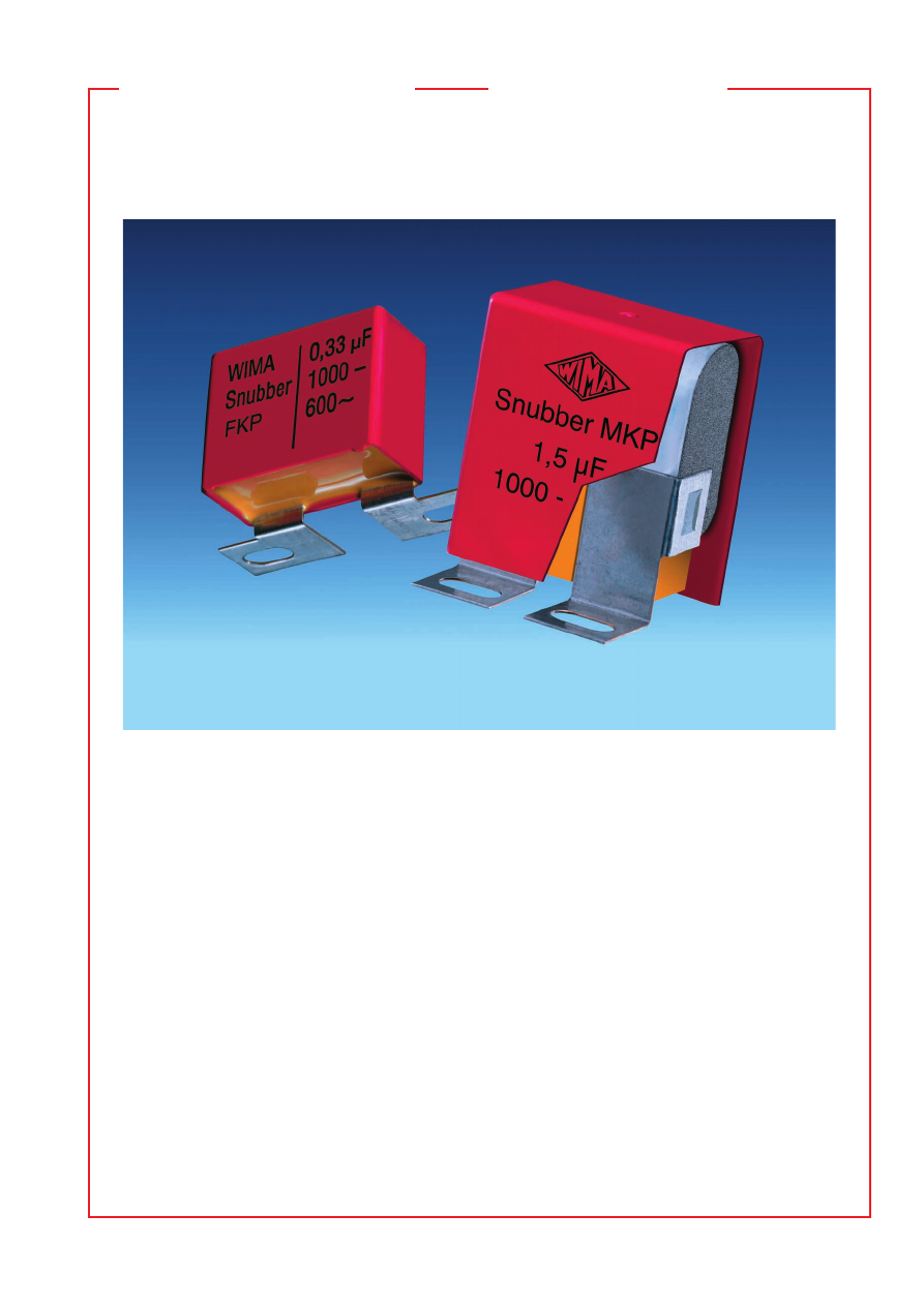
WIMA Snubber FKP


und 

WIMA Snubber MKP

 für die Bedürfnisse der Hochleistungs-

Umrichtertechnik entwickelt.

WIMA Snubber Kondensatoren stehen in doppelseitig metallisier-
ter, impulsfester Ausführung als Snubber MKP und für höchste 
Impulsbelastungen in ausheilfähiger Film/Folien-Technologie als 
Snubber FKP zur Verfügung. Ihre elektrische Performance sowie 
die vielfältigen optionalen Anschlußkonfigurationen machen die 
WIMA Snubber Technologie in ihrer Form einzigartig:

˜

 Direkt kontaktierte Anschlußlaschen für sicheren Kontakt

bei hoher Dauerstrombelastung.

˜

 Induktionsarmer Aufbau durch Stirnkontaktierung.

˜

 Hohe Impulsbelastbarkeit aufgrund doppelseitiger

Metallisierung bzw. Film/Folien Aufbau.

˜

 Hohe Spannungs-/Überspannungsfestigkeit durch innere

Reihenschaltung mit ausheilfähiger, metallisierter Blindlage.

˜

 Verfügbar in verschiedensten Anschlußkonfigurationen.

˜

 Flammhemmendes Kunststoffgehäuse gemaß UL 94 V-0.

˜

 Fertigungsstandorte zertifiziert nach ISO 9000.

WIMA Snubber Kondensatoren werden unter Großserienbedin-
gungen gefertigt, stehen jedoch auch in kleineren Stückzahlen als
individuell konfigurierbare High-Rel. Bauelemente zur Verfügung.

Decades of experience with polypropylene pulse capacitors
are involved in the development of the 

WIMA Snubber FKP


and 

WIMA Snubber MKP

 capacitor series for high power con-

version.

WIMA Snubber capacitors are available both as double-sided 
metallized pulse version - WIMA Snubber MKP - and for ex-
tremely high pulse ratings in self-healing film/foil technology 
- WIMA Snubber FKP. Their electrical performance as well as 
the manifold number of available connecting options makes the 
WIMA Snubber technology unique:

˜

 Tags soldered directly to the schoopage for safe contacts

at high rms currents.

˜

 Low inductance construction achieved by end-surface contacts.

˜

 High pulse reliability due to double-sided metallization

and/or film and foil construction.

˜

 High voltage/overvoltage strength by internal series

connection with self-healing metallized floating electrode.

˜

 Available in various contact configurations.

˜

 Flame retardent plastic case, UL 94 V-0.

˜

 Production sites ISO 9000 certified.

WIMA Snubber capacitors are manufactured under high quantity 
conditions thus also being available in small quantities as indivi-
dually configurable high-rel. components.

Snubber capacitors
for best contacts

Snubber Kondensatoren
für beste Verbindungen

pa/wima/wima_snubber_capacitors-html.html
background image

74

01-04

Technische Angaben

Dielektrikum:

 Polypropylen-Folie.

Beläge:

 Doppelseitig metallisierte Kunststoff-Folie.

Umhüllung:

 Flammhemmendes Kunststoffgehäuse, UL 94 V–0.

Farbe: Rot. Aufdruck: Schwarz. Epoxidharzverguß: Gelb.

Temperaturbereich:

 –55

)

 C bis +100

)

 C.

Prüfklasse:

 55/100/56 nach IEC.

Isolationswerte

 bei +20

)

 C:

 0,33

 m

F:


 1 

 10

5

 M

V

 (Mittelwert: 5


 10

5

 M

V

)

C  

 0,33

 m

F:


 30 000 s (M

V


m

F) (Mittelwert: 100 000 s)

Meßspannung: 100 V/1 min.

Verlustfaktoren

 bei +20

)

 C: tan 

d

Kapazitätstoleranzen:


±

 20 %, 

±

 10 %, 

±

 5 %, andere Toleranzen 

auf Anfrage.

Impulsbelastung:

Prüfspannung:

 1,2 bis 1,6 U

N

, 2 s.

Spannungsderating:

 Die zulässige Spannung vermindert sich 

gegenüber der Nennspannung bei Gleichspannungsbetrieb ab 
+85

)

 C, bei Wechselspannungsbetrieb ab +75

)

 C um 1,35 %

je 1 K.

Kurven siehe Seite 7.

Montagehinweis:

 Beim Montieren und in der Anwendung der 

Kondensatoren ist übermäßige mechanische Beanspruchung, z.B.
durch Druck oder Stoß auf das Kondensatorgehäuse, zu ver-
meiden. Beim Befestigen der Laschen ist das Drehmoment der 
Schrauben auf 5 Nm max. zu begrenzen.

  WIMA Snubber MKP

High performance
IGBT-Snubber Kondensatoren

˜

  Induktionsarmer  Aufbau  mit  Stirnkontaktie-

rung.      

˜

  Hohe  Impulsbelastbarkeit.      

˜

  Verlustar-

mes  Polypropylendielektrikum.      

˜

  Innere  Reihen-

schal tung.      

˜

  Ausheilfähiger  Aufbau.      

˜

  Verfüg-

bar in verschiedenen Anschluss konfigurationen.

High performance
IGBT-snubber capacitors

˜

  Low  inductive  construction  with  end-surface

contacts.      

˜

  For  high  pulse  ratings.      

˜

  Low-loss

polypropylene  dielectric.   

˜

  Internally  series-

connected.   

˜

  Self-healing  construction.      

˜

  Avail-

able in various confi gurations.

 Gemessen bei  C 

 0,1 

m

0,1 

m

 C 

 1 

m

 1 

m

F


    1 kHz 

   3 

 10

-4


 3 

 10

-4


 3 

 10

-4


  10 kHz 

   4 

 10

-4


 6 

 10

-4 


100 kHz 

 10 

 10

-4


– 

Technical Data

Dielectric:

 Polypropylene film.

Capacitor electrodes:

 Double-sided metallized plastic film.

Encapsulation:

 Flame-retardent plastic case, UL 94 V–0.

Colour: Red. Marking: Black. Epoxy resin seal: Yellow.

Temperature range:

 –55

)

 C to +100

)

 C.

Test category:

 55/100/56 in accordance with IEC.

Insulation resistance

 at +20

)

 C:

 0.33 

m

F: 

 1 x 10

5

 M

V

 (mean value: 5 x 10

5

 M

V

)

C  

 0.33 

m

F: 

 30 000 sec (M

V

 x 

m

F) (mean value: 100 000 sec)

Measuring voltage: 100 V/1 min.

Dissipations factors

 at +20

)

 C: tan 

d

Capacitance tolerances:


±

 20 %, 

±

 10 %, 

±

 5 % 

(closer tolerances are available subject to special enquiry).

Maximum pulse rise time:

Test voltage:

 1.2 through 1.6 Ur, 2 sec.

Voltage derating:

 A voltage derating factor of 1.35 % per K 

must be applied from +85

)

 C for DC voltages and from +75

)

 C

for AC voltages.

Graphs see page 7.

Mounting recommendation:

 Excessive mechanical strain, e.g. 

pressure or shock onto the capacitor body, is to be avoided 
during mounting and usage of the capacitors. When fixing the 
tabs the screw torque is to be limited to max. 5 Nm.


at f 

 0.1 

m

0.1 

m

 C 

 1 

m

 1 

m

F


    1 kHz 

   3 x 10

-4


 3 x 10

-4


 3 x 10

-4


  10 kHz 

   4 x 10

-4


 6 x 10

-4 


100 kHz 

 10 x 10

-4


– 


C-Wert


            Flankensteilheit V/

m

s


m

F


                 max. Betrieb


250 V–  400 V–  630 V–  1000 V–  1600 V– 2000 V–  3000 V–

 0,047. . . 0,22  130 

150 

600 

700 

800 

800 

800 

 0,33  . . . 0,68    85 

100 

450 

550 

650 

650 

650

 1,0    . . . 2,2 

  65 

  75 

300 

400 

500 

500 

500

 2,5    . . . 6,0 

  50 

  60 

150 

300 

400 

– 

 7,0    . . . 10 

  10 

  15 

  15 

– 

– 

– 

15     . . . 25 

    5 

  10 

– 

– 

– 

– 


Capacitance


              Pulse rise time V/

m

s


m

F


                 max. operation


250 VDC  400 VDC  630 VDC  1000 VDC  1600 VDC  2000 VDC  3000 VDC

 0.047. . . 0.22  130 

150 

600 

700 

800 

800 

800 

 0.33  . . . 0.68    85 

100 

450 

550 

650 

650 

650

 1.0    . . . 2.2 

  65 

  75 

300 

400 

500 

500 

500

 2.5    . . . 6.0 

  50 

  60 

150 

300 

400 

– 

 7.0    . . . 10 

  10 

  15 

  15 

– 

– 

– 

15     . . . 25 

    5 

  10 

– 

– 

– 

– 

pa/wima/wima_snubber_capacitors-html.html
background image

75

01-04

    Kapazität 

250 VDC/180 VAC*  400 VDC/250 VAC*  630 VDC/400 VAC*  1000 VDC/600 VAC*  1600 VDC/650 VAC``*  2000 VDC/700 VAC``*  3000 VDC/700 VAC*

  Capacitance  W  H 

L


0.047  

m


10.5  19 

26.5  11 

21  31.5


0.068 „ 


 7 

16.5  26.5  10.5  19  26.5  11 

21 

26.5  13  24  31.5


11 

22  41.5


0.1     

m

 5 

11 

18 

 7 

14 

18 

 7 

16.5  26.5    8.5  18.5  26.5  11 

21  26.5  13 

24 

31.5  15  26  31.5


11 

22 

41.5  13  24  41.5


0.15   „ 

 6 

12.5  18 

 8 

15 

18 

8.5  18.5  26.5  11 

21 

26.5  13 

24  31.5  15 

26 

31.5  15  26  41.5


11 

22  41.5  13 

24 

41.5


0.22   „ 

 7 

14 

18 

 7 

16.5  26.5  10.5  19 

26.5  11 

21 

31.5  15 

26  31.5  17 

34.5  31.5  19  32  41.5


13 

24  41.5  15 

26 

41.5


0.33   „ 

 8 

15 

18 

8.5  18.5  26.5  11 

21 

26.5  15 

26 

31.5  17 

34.5  31.5  19 

32 

41.5  19  31  56


13 

24 

41.5  15 

26  41.5


0.47   „ 

 7 

16.5  26.5  10.5  19 

26.5  11 

21 

31.5  17 

29 

31.5  19 

32  41.5  20 

39.5  41.5  27  37.5  56


15 

26 

41.5


0.68   „ 

 8.5  18.5  26.5  11 

21 

31.5  15  26 

31.5  17 

29 

41.5  20 

39.5  41.5  24 

45.5  41.5  33  48  56


13  24 

41.5


1.0     

m

11  21 

26.5  13  24 

31.5  17  29 

31.5  20 

39.5  41.5  24 

45.5  41.5  33 

48 

56 

33  48  56


13  24 

41.5  15  26 

41.5


1.5     „ 

13  24 

31.5  17  29 

31.5  19  32 

41.5  24 

45.5  41.5  31 

46  41.5  33 

48 

56 

37  54  56


11  22 

41.5  15  26 

41.5


2.0     „ 

15  26 

31.5  17  29 

41.5  20  39.5  41.5  31 

46 

41.5  33 

48  56 

37 

54 

56


13  24 

41.5


2.2     „ 

15  26 

31.5  17  29 

41.5  20  39.5  41.5  31 

46 

41.5  33 

48  56


13  24 

41.5


2.5     „ 

17  29 

31.5  19  32 

41.5  24  45.5  41.5  33 

48 

56 

37 

54  56


15  26 

41.5


3.0     „ 

17  34.5  31.5  20  39.5  41.5  24  45.5  41.5  33 

48 

56 

37 

54  56


15  26 

41.5


3.3     „ 

17  34.5  31.5  20  39.5  41.5  24  45.5  41.5  33 

48 

56


15  26 

41.5


4.0     „ 

19  32 

41.5  24  45.5  41.5  31  46 

41.5  37 

54 

56


4.7    „ 

19  32 

41.5  24  45.5  41.5  31  46 

41.5


5.0     „ 

20  39.5  41.5  24  45.5  41.5  31  46 

41.5  37 

54 

56


6.0     „ 

20  39.5  41.5  31  46 

41.5  33  48 

56


7.0     „ 

24  45.5  41.5  31  46 

41.5  33  48 

56


8.0     „ 

24  45.5  41.5  33  48 

56 

37  54 

56


10.0   

m

31  46 

41.5  33  48 

56 


* Wechselspannungen: f 

 1000 Hz; 1,4 

 U

eff


Z

 + U– 

 U

N


15.0   „ 

33  48 

56 

37  54 

56 


* AC voltage: f 

 1000 Hz; 1.4 x Urms + UDC 

 Ur


20.0   „ 

37  54 

56


25.0   „ 

37  54 

56 


      Neue Werte und Spannungsreihen./New values and voltage ranges.

Bei Bestellung bitte die gewünschte Bauform und Ausführung angeben. Ausführungen und Maßzeichnungen siehe 78.
On ordering please state the required version and box size. Versions and dimensional drawings see 78.
Alle Maße in mm./Dims. in mm.

Abweichungen und Konstruktionsänderungen vorbehalten. /Rights reserved to amend design data without prior notification.

                              WIMA Snubber MKP

Werteübersicht / General Data

Zulässige Wechselspannung in Abhängigkeit von der Frequenzbei 10

)

 C Eigenerwärmung (Richtwerte):

Permissible AC voltage in relation to frequency at 10

)

 C internal temperature rise (general guide):

250 VDC

f

Hz

10

2              5        10

2              5        10

2              5       10

3

4

5

6

5

2

10

5

2

10

180

2

1

U

V

rms

0.1 µF

0.2

2 µ

F

0.4

7 µ

F

1.0

 µF

4.0 µF

6.0 µF

10  µF

20  µF

25  µF

15 µF

8.0 µF

3.0 µF

2.0 µF

630 VDC

f

Hz

10

2              5        10

2              5        10

2              5       10

3

4

5

6

5

2

10

5

2

10

400

2

1

U

V

rms

0.1 µF

0.2

2 µ

F

3.0

 µF

0.4

7 µ

F

1.0

 µF

1.5 µF

4.0 µF

6.0 µF

8.0 µF 5.0 µF

2.0 µF

0.47 µF

0.2

2 µ

F

0.0

68 µ

F

0.1

 µF

1.0

 µF

2.0

 µF

3.0

 µF

4.0

 µF

5.0

 µF

1000 VDC

f

Hz

10

2              5        10

2               5        10

2              5       10

3

4

5

6

5

2

10

5

2

10

600

2

1

U

V

rms

1.0

 µF

2.0

 µF

3.0

 µF

0.2

2 µ

F

0.4

7 µ

F

1.5

 µF

0.068 µF

0.1

 µF

1600 VDC

f

Hz

10

2              5        10

2               5       10

2              5       10

3

4

5

6

5

2

10

5

2

10

650

2

1

U

V

rms

0.47 µF

0.2

2 µ

F

0.1

 µF

1.0

 µF

2.0

 µF

6.0

 µF

10  

µF

4.0

 µF

8.0

 µF

15  

µF

400 VDC

f

Hz

10

2              5        10

2               5        10

2              5       10

3

4

5

6

5

2

10

5

2

10

250

2

1

U

V

rms

0.2

2 µ

F

0.4

7 µ

F

1.0

 µF

0.0

47 µ

F

0.1

 µF

2.0

 µF

2000 VDC

3000 VDC

f

Hz

10

2              5        10

2               5        10

2              5       10

3

4

5

6

5

2

10

5

2

10

700

2

1

U

V

rms

pa/wima/wima_snubber_capacitors-html.html
background image

76

01-04

  WIMA Snubber FKP

High performance
IGBT-Snubber Kondensatoren

˜

  Induktionsarmer  Aufbau  mit  Stirnkontaktie-

rung.  

˜

  Höchste  Kontaktsicherheit  durch  stirn-

seitig  schoopierte  Beläge. 

˜

  Verlustarmes  Poly-

propylendielek trikum.      

˜

  Innere  Reihenschaltung. 

˜

  Ausheilfähiger  Aufbau.      

˜

  Verfüg bar  in  versch. 

Anschlusskon figurationen.

High performance
IGBT-snubber capacitors

˜

  Low  inductive  construction  with  end-surface 

contacts.      

˜

  Excellent  contact  reliability  because 

of  metal  sprayed  end-surfaces.      

˜

  Low-loss 

polypropylene dielectric.      

˜

  Internally series con-

nected.      

˜

  Self-healing  construction.      

˜

  Available

in various configurations.

 Gemessen bei  C 

 0,1 

m

0,1 

m

 C 

 1 

m

 1 

m

F


    1 kHz 

   3 

 10

-4


 3 

 10

-4


 3 

 10

-4


  10 kHz 

   4 

 10

-4


 6 

 10

-4 


100 kHz 

 10 

 10

-4


– 


at f 

 0.1 

m

0.1 

m

 C 

 1 

m

 1 

m

F


    1 kHz 

   3 x 10

-4


 3 x 10

-4


 3 x 10

-4


  10 kHz 

   4 x 10

-4


 6 x 10

-4 


100 kHz 

 10 x 10

-4


– 


C-Wert


             Flankensteilheit V/

m

s


m

F


                max. Betrieb


630 V–  1000 V– 1600 V– 2000 V– 3000 V– 4000 V–

 0,01   . . . 0,022 

– 

5000 

6400 

7650 

8100 

8500

 0,033 . . . 0,068  2000 

3800 

4400 

4500 

5100 

5600

 0,1     . . . 0,22

0

  1300 

2000 

3200 

3500 

4200 

4600

 0,33   . . . 0,68

0

  1000 

1800 

2500 

3000 

3300 

3800

 1,0     . . . 2,2

00

    800 

1200 

– 

– 

– 


Capacitance


             Pulse rise time V/

m

sec


m

F


                max. operation


630 VDC  1000 VDC  1600 VDC  2000 VDC  3000 VDC  4000 VDC

 0.01   . . . 0.022 

– 

5000 

6400 

7650 

8100 

8500

 0.033 . . . 0.068  2000 

3800 

4400 

4500 

5100 

5600

 0.1     . . . 0.22

0

  1300 

2000 

3200 

3500 

4200 

4600

 0.33   . . . 0.68

0

  1000 

1800 

2500 

3000 

3300 

3800

 1.0     . . . 2.2

00

    800 

1200 

– 

– 

– 

Technische Angaben

Dielektrikum:

 Polypropylen-Folie.

Beläge:

 Aluminiumfolie und einseitig metallisierte Kunststoff-Folie.

Umhüllung:

 Flammhemmendes Kunststoffgehäuse, UL 94 V–0.

Farbe: Rot. Aufdruck: Schwarz. Epoxidharzverguß: Gelb.

Temperaturbereich:

 –55

)

 C bis +100

)

 C.

Prüfklasse:

 55/100/56 nach IEC.

Isolationswerte

 bei +20

)

 C:

 0,33

 m

F:


 1 

 10

5

 M

V

 (Mittelwert: 5


 10

5

 M

V

)

C  

 0,33

 m

F:


 30 000 s (M

V


m

F) (Mittelwert: 100 000 s)

Meßspannung: 100 V/1 min.

Kapazitätstoleranzen:


±

 20 %, 

±

 10 %, 

±

 5 %, 

andere Toleranzen auf Anfrage.

Verlustfaktoren

 bei +20

)

 C: tan 

d

Kapazitätstoleranzen: 

± 

20%, 

± 

10%, 

± 

5%, andere Toleranzen

auf Anfrage.

Impulsbelastung:

Prüfspannung:

 1,2 bis 1,6 U

N

, 2 s.

Spannungsderating:

 Die zulässige Spannung vermindert sich 

gegenüber der Nennspannung bei Gleichspannungsbetrieb ab 
+85

)

 C, bei Wechselspannungsbetrieb ab +75

)

 C um 1,35 %

je 1 K.

Kurven siehe Seite 7.

Montagehinweis:

 Beim Montieren und in der Anwendung der 

Kondensatoren ist übermäßige mechanische Beanspruchung, z.B.
durch Druck oder Stoß auf das Kondensatorgehäuse, zu ver-
meiden. Beim Befestigen der Laschen ist das Drehmoment der 
Schrauben auf 5 Nm max. zu begrenzen.

Technical Data

Dielectric:

 Polypropylene film.

Capacitor electrodes:

 Aluminium foil and metallized plastic film.

Encapsulation:

 Flame-retardent plastic case, UL 94 V–0.

Colour: Red. Marking: Black. Epoxy resin seal: Yellow.

Temperature range:

 –55

)

 C to +100

)

 C.

Test category:

 55/100/56 in accordance with IEC.

Insulation resistance

 at +20

)

 C:

 0.33 

m

F: 

 1 x 10

5

 M

V

 (mean value: 5 x 10

5

 M

V

)

C  

 0.33 

m

F: 

 30 000 sec (M

V

 x 

m

F) (mean value: 100 000 sec)

Measuring voltage: 100 V/1 min.

Capacitance tolerances:


±

 20 %, 

±

 10 %, 

±

 5 % 

(closer tolerances are available subject to special enquiry).

Dissipations factors

 at +20

)

 C: tan 

d

Capacitance tolerances: 

± 

20%, 

± 

10%, 

± 

5%,

(closer tolerances are available subject to special enquiry).

Maximum pulse rise time:

Test voltage:

 1.2 through 1.6 Ur, 2 sec.

Voltage derating:

 A voltage derating factor of 1.35 % per K 

must be applied from +85

)

 C for DC voltages and from +75

)

 C

for AC voltages.

Graphs see page 7.

Mounting recommendation:

 Excessive mechanical strain, e.g. 

pressure or shock onto the capacitor body, is to be avoided during 
mounting and usage of the capacitors. When fixing the tabs the 
screw torque is to be limited to max. 5 Nm.

pa/wima/wima_snubber_capacitors-html.html
background image

77

01-04


Kapazität 

630 VDC/400 VAC*  1000 VDC/600 VAC* 1600 VDC/650 VAC``*  2000 VDC/700 VAC``* 3000 VDC/700 VAC* 4000 VDC/700 VAC*

  Capacitance 

L


0.01   

m


  7 

16.5  26.5  10.5  20.5  26.5  11 

21 

26.5  11 

21 

31.5


0.015 „ 


  8.5  18.5  26.5  11 

21 

26.5  11 

21 

31.5  11 

22 

41.5


0.022 „ 


  7 

16.5  26.5  10.5  20.5  26.5  11 

21 

31.5  13 

24 

31.5  13 

24 

41.5


11 

22 

41.5


0.033 „ 


  8.5  18.5  26.5  11 

21 

31.5  13 

24 

41.5  13 

24 

41.5  15 

26 

41.5


0.047 „ 

  7 

16.5  26.5  10.5  20.5  26.5  11 

22 

41.5  15 

26 

41.5  15 

26 

41.5  17 

29 

41.5


0.068 „ 

  8.5  18.5  26.5  11 

21 

31.5  15 

26 

41.5  17 

29 

41.5  17 

29 

41.5  19 

32 

41.5


0.1     

m

10.5  20.5  26.5  11 

22 

41.5  17 

29 

41.5  17 

29 

41.5  19 

32 

41.5  20 

39.5  41.5


0.15   „ 

11 

21 

26.5  15 

26 

41.5  19 

32 

41.5  20 

39.5  41.5  20 

39.5  41.5  24 

45.5  41.5


0.22   „ 

13 

24 

31.5  17 

29 

41.5  20 

39.5  41.5  24 

45.5  41.5  24 

45.5  41.5  27 

37.5  56


0.33   „ 

15 

26 

31.5  19 

32 

41.5  24 

45.5  41.5  27 

37.5  56 

27 

37.5  56 

33 

48 

56


0.47   „ 

17 

29 

41.5  20 

39.5  41.5  27 

37.5  56 

27 

37.5  56 

33 

48 

56


0.68   „ 

19 

32 

41.5  23 

34 

56 

27 

37.5  56 


1.0     

m

20 

39.5  41.5  27 

37.5  56


1.5     „ 

24 

45.5  41.5 


2.2     „ 

27 

37.5  56

* Wechselspannungen: f 

 1000 Hz; 1,4 

 U

eff


Z

 + U– 

 U

N

* AC voltage: f 

 1000 Hz; 1.4 x Urms + UDC 

 Ur 


Neue Spannungsreihen.


New voltage ranges.

Bei Bestellung bitte die gewünschte Bauform und Ausführung angeben.
Ausführungen und Maßzeichnungen siehe 78.

On ordering please state the required version and box size.
Versions and dimensional drawings see 78.

Alle Maße in mm./Dims. in mm.

Abweichungen und Konstruktionsänderungen vorbehalten.
Rights reserved to amend design data without prior notification.

0.0

22 µ

F

0.47

 µF/0

.68 µ

F

0.2

2 µ

F

0.3

3 µ

F

0.0

47 µ

F

0.1

 µF

1.0

 µF

1000 VDC

f

Hz

10

2              5        10

2               5        10

2              5       10

3

4

5

6

5

2

10

5

2

10

600

2

1

Urms

V

0.0

1 µ

F

0.2

2 µ

F

0.6

8 µ

F

0.1

5 µ

F

0.3

3 µF

/0.4

7 µF

0.0

47 µ

F

0.0

22 µ

F

0.1

 µF

1600 VDC

f

Hz

10

2              5        10

2               5        10

2              5       10

3

4

5

6

5

2

10

5

2

10

650

2

1

Urms

V

0.0

1 µ

F

0.2

2 µ

F

0.4

7 µ

F

0.15

 µF

0.3

3 µ

F

0.0

47 µ

F

0.0

22 µ

F

0.1

 µF

2000 VDC

f

Hz

10

2              5        10

2               5        10

2              5       10

3

4

5

6

5

2

10

5

2

10

700

2

1

Urms

V

0.0

1 µ

F

0.2

2 µ

F

0.15

 µF

0.3

3 µ

F

0.0

47 µ

F

0.0

22 µ

F

0.1

 µF

4000 VDC

f

Hz

10

2              5        10

2               5        10

2              5       10

3

4

5

6

5

2

10

5

2

10

700

2

1

Urms

V

0.0

1 µ

F

0.2

2 µ

F

0.4

7 µ

F

0.15

 µF

0.33

 µF

0.0

47 µ

F

0.0

22 µ

F

0.1

 µF

3000 VDC

f

Hz

10

2              5        10

2               5        10

2              5       10

3

4

5

6

5

2

10

5

2

10

700

2

1

Urms

V

630 VDC

f

Hz

10

2              5        10

2               5        10

2               5       10

3

4

5

6

5

2

10

5

2

10

400

2

1

Urms

V

0.1

 µF

0.2

2 µ

F

0.3

3 µ

F

0.4

7 µ

F

0.68

 µF

1.0 µ

F

1.5 µF/2.

2 µF

0.04

7 µF

                              WIMA Snubber FKP

Werteübersicht / General Data

Zulässige Wechselspannung in Abhängigkeit von der Frequenz bei 10

)

 C Eigenerwärmung (Richtwerte):

Permissible AC voltage in relation to frequency at 10

)

 C internal temperature rise (general guide):

pa/wima/wima_snubber_capacitors-html.html
background image

78

01-04

Versions of WIMA snubber 
capacitors

Konstruktionsarten der 
WIMA Snubber Kondensatoren

Version    L       a      b       c     h

41.5 17.5  27.5  7.5  3.5

56     21    31     11   3.5

41.5 17.5  27.5  7.5  0

56    19     29     9     0

A1

A1

A1.5

A1.4

L

H

15      c      15

W

14

0.6

b

a

7.56.1

h

Version    L       c        h

41.5    2      3.5

56       8      3.5

41.5    2      0

56       8      0

A1.8

A1.9

A1.2

A1.1

L

H

15

W

14

0.6

h

14

W+1

5

W+2

8

c

5

6.1

Version    L      a       b

41.5  18      6

56      29    17

A1.6

A1.6

L

H

12      b     12

W

20.5

0.6

a

7

15

Version     L         a

41.5     7.5

56        9

A1.7

A1.7

L

H

15       a     15

W

0.6

3.5

Version   L      a       b      c      d      e      h

41.5 40.5 46.5 14.5  8.4  7.5    0

56    39.5 45.5 13.5  8.4  7.5    0

41.5 31    37     5      8.4  7.5   3.5

41.5 31    37     5      8.4  13    3.5

41.5 33.5 39.5  7.5   8.4  13    3.5

41.5 29.5 39.5  5.5   6.1  7.5   3.5

41.5 31.5 41.5  7.5   6.1  13    3.5

56    39.5 45.5 13.5  8.4  7.5   3.5

41.5 40.5 46.5 14.5  8.4  7.5   3.5

A2

A2.1

A2.2

A2.3

A2.4

A2.5

A2.6

A2.7

A2.8

22

22

c

L

H

d

b

a

e

W

14

19.5

0.6

h

Version    L      a       b      c      h

41.5 17.5 27.5  7.5    0

56    19    29     9       0

56    28    38     18     0

41.5 17.5 27.5  7.5    3

56    19    29     9       3

56    28    38     18     3

A3

A3

A3.1

A3.5

A3.5

A3.10

W

17

h

0.6

6.1

b

a

6.5

L

H

15      c     15

pa/wima/wima_snubber_capacitors-html.html
background image

79

01-04

Versions of WIMA snubber 
capacitors

Konstruktionsarten der 
WIMA Snubber Kondensatoren

Version    L       a      b      c      h

41.5 40.5 46.5 14.5   0

56    39.5 45.5 13.5   0

41.5 40.5 46.5 14.5   3

56    39.5 45.5 13.5   3

A3.9

A3.2

A3.11

A3.3

W

17

0.6

8.4

b

a

6.5

L

H

22        c       22

h

Version    L      a       b      c

41.5 17.5 27.5  7.5

56     19   29     9

A3.6

A3.7

W

17

0.6

6.1

b

a

6.5

L

H

15      c     15

Version    L       a       b

41.5   18      6

A3.8

W

23

0.6

7

a

5.5

L

H

12       b     12

c

b

a

12 d

L

H

W

0.6

Version         L             a      b       c      d

41.5 W 15   54    57           4.5

56                 64    80    90   6.1

67

41.5 W 15   53    69    79   6.1

56                 65    68    78   4.5

A4.2

A4

A4

A4.7

Version    L       a       b       c

41.5  17.5  27.5  7.5

56      19    29     9

A5

A5

L

H

15

15

c

W

14

0.6

14

W+1

5

W+2

8

6.1

7.5

6.5

b

a

Version    L     a      b      c      d      h      W

41.5 18     8      5      6    3.5    17

A4.1

31.5 19     8      6      1    3.5    19

31.5 19     8      6      1    0       19

41.5 18     8      5      6    0       17

31.5 12.8 1.5   6.3    1    3.5    19

31.5 12.8 1.5   6.3    1    0       19

A4.3

A4.4

A4.5

A4.6

A4.8

L

H

a

6.1

b

c

12 d

W

0.6

h

pa/wima/wima_snubber_capacitors-html.html
background image

80

01-04

4-lead version

L

PCM

=P.C. Module

at the lead exit points

( 0.4)


W

H

b

( 0.4)


6

-1

d

W     H       L     PCM     b      d

10.5  19     26.5  22.5   5       0.8

10.5  20.5  26.5  22.5   5       0.8

11     21     26.5  22.5   5       0.8

11     21     31.5

13     24     31.5

15     26     31.5

17     29     31.5

19     30     31.5

17     34.5  31.5

11     22     41.5

13     24     41.5

15     26     41.5

17     29     41.5

19     32     41.5

20     39.5  41.5

24     45.5  41.5

31     46     41.5

19     31     56

23     34     56

27     37.5  56

33     48     56

37     54     56

27.5   5       0.8

27.5   7.5    0.8

27.5   7.5    0.8

27.5   10     1

27.5   10     1

27.5   10     1

20     39.5  31.5  27.5   12.5  1

22     43.5  31.5  27.5   12.5  1

37.5   5       1

37.5   7.5    1

37.5   7.5    1

37.5   10     1

37.5   10     1

37.5   12.5  1

37.5   12.5  1

37.5   20     1

48.5   12.5  1

48.5   15     1

48.5   15     1

48.5   20     1

48.5   20     1

Versions of WIMA snubber 
capacitors

Konstruktionsarten der 
WIMA Snubber Kondensatoren

Version B

L

PCM

=P.C. Module

at the tabs exit points

( 0.4)


W

H

b

6

-1

0.5

L    PCM    b

26.5  23.5   5

31.5  28.5   8

41.5  38.5   8

56     49.5   8

2-lead version

L

PCM

=P.C. Module

at the lead exit points

( 0.4)


W

H

6

-1

d

PCM    d

28.5   1

38.5   1.2

49.5   1.2

2-

le

ad

4-

le

ad

B5 B8 A1 A1.

1

A1.

2

A1.

4

A1.

5

A1.

6

A1.

7

A1.

8

A1.

9

A2 A2.

1

A2.

2

A2.

3

A2.

4

A2.

5

A2.

6

A2.

7

A2.

8

A3 A3.

1

A3.

2

A3.

3

A3.

5

A3.

6

A3.

7

A3.

8

A3.

9

A3.

10

A3.

11

A4 A4.

1

A4.

2

A4.

3

A4.

4

A4.

5

A4.

6

A4.

7

A4.

8

A5 FS 6.

3

5x11x18

6x12.5x18

7x14x18

8x15x18

7x16.5x26.5

8.5x18.5x26.5

10.5x19x26.5

10.5x20.5x26.5

11x21x26.5

11x21x31.5

13x24x31.5

15x26x31.5

17x29x31.5

19x30x31.5

17x34.5x31.5

11x22x41.5

13x24x41.5

15x26x41.5

17x29x41.5

19x32x41.5

20x39.5x41.5

24x45.5x41.5

28x38x41.5

31x46x41.5

19x31x56

23x34x56

27x37.5x56

33x48x56

37x54x56

Alle Maße in mm.
Dims. in mm.

Weitere Sonderausführungen 
sind realisierbar. Bitte nennen 
Sie uns Ihre Vorstellungen.

Additional special versions can 
be realized. Please contact
us with your specific needs.

L       W    PCM    b

26.5

23.5   6.3

31.5

28.5   6.3

41.5

38.5   6.3

56

49.5   6.3

11

11

11

11

Version FS 6.3

für Flachstecker

nach DIN 46244

with slip-on terminals

according to DIN 46244

L

PCM

=P.C. Module

at the tabs exit points

( 0.4)


W

H

b

8

0.8

Mögliche Anschluss- bzw. Laschenausführungen – gehäusegrößenbezogen.
Possible connecting respective tab versions – depending on box sizes.