background image

Copper Compression

Metric Lugs and Splices

• Optimum reliability and safety

• Worldwide availability
• RoHS compliant
• Standard barrel lugs and splices for copper class 2r rigid stranded conductor sizes 4mm

2

 – 630mm

2

,


  copper class 5f flexible stranded conductor sizes 4mm

2

 – 300mm

2

 and copper class 6f flexible stranded 

  conductor sizes 10mm

2

 – 240mm

2

• Standard barrel lugs with 45° and 90° bent palms for copper class 2r rigid stranded conductor sizes 10mm

–  

  300 mm

2

, copper class 5f flexible stranded conductor sizes 10mm

– 300mm

2

 and copper class 6f flexible stranded  

  conductor sizes 10mm

– 240mm

2

• Long barrel lugs for copper class 2r rigid stranded conductor sizes 10mm

2

 – 630mm

2

, copper class 5f 

  flexible stranded conductor sizes 10mm

2

 – 300mm

2

, and copper class 6f flexible stranded conductor sizes

  10mm

2

 – 240mm

2

w w w . p a n d u i t . c o m

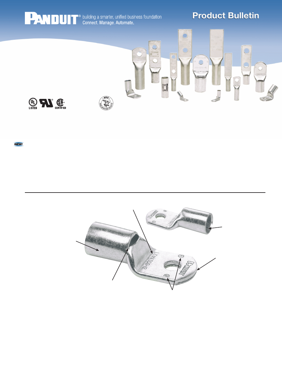
K e y   F e a t u r e s   a n d   B e n e f i t s

99.9% Pure Copper
and Tin Plated

 to a

nominal thickness of
320μ in (8μ m) to
provide a high quality
connection

Product Information Marked
on Connector

 for easy

selection and installation

Inspection Window for 
Standard Barrel Lugs

allows a visually
verifiable, high
quality crimp

UL Listed or UL Recognized
and CSA Certified with Metric
Conductors

 allows specification

to ensure safety and reliability

Internally Beveled
Wire Entry

 for fast

and easy installation

Rounded Tongue for 
One-Hole Lugs

convenient for use
in tight spaces

With Metric
Conductors

panduit-compression-lugs-html.html
background image

Part Number System

Rigid Stranded Metric Conductor, One-Hole, Standard Barrel

with Window Lug

2

LCMD 

150  – 12 

–  X

LCMA 

150  – 12 

H  –  X

Type

LCMD = Two-Hole Standard Barrel Lug, Class 2r

LCMA = One-Hole Standard Barrel Lug, Class 2r

SCMS = Splice, Class 2r

LCMDX = Two-Hole Standard Barrel Lug, Class 5f and 6f

LCMAX = One-Hole Standard Barrel Lug, Class 5f and 6f

SCMSX = Splice, Class 5f and 6f

LCMA-H = One-Hole Standard Barrel 45° Bent Lug, Class  

                  2r, 5f and 6f

LCMA-F = One-Hole Standard Barrel 90° Bent Lug, Class  

                 2r, 5f and 6f

LCMB = One-Hole Long Barrel Lug, Class 2r, 5f and 6f

LCMC = Two-Hole Long Barrel Lug, Class 2r, 5f and 6f

Conductor Size

150 = 150mm

2

*

*Class 2r wire size for LCMA-H, LCMA-F, LCMB and LCMC lugs

Stud Hole Size

12 = M12

Two Stud

Hole Spacing

No Letter = 44.5mm

CD = 22.0 – 25.0mm

00 = Blank Tongue

N

M

INSPECTION

WINDOW

I

L

B

B

INSPECTION

WINDOW

L

I

Figure 1.

One-Hole

Figure 2.

Blank Tongue

To 35 KV**

Rated to 90°C

and EN 61238-1:2003/IEC 61238-1:2003 Class B, sizes 4mm

2

 – 240mm

Class 2r

Part Number

Figure

No.

Copper

Conductor

Size Class 2r 

(mm

2

)

Current

Rating

(Amps)

Stud 

Hole

Size

(mm)

Figure Dimensions

(mm)

Panduit

Die Index

No.‡

Std. 

Pkg. 

Qty.

ØI

B

M

N

L

LCMA6-5-C*

1

4 – 6

30

M5

3.8

10.0

7.8

6.2

27.5

P10

100

LCMA6-6-C*

1

4 – 6

30

M6

3.8

10.8

7.8

6.2

27.5

P10

100

LCMA6-8-C*

1

4 – 6

30

M8

3.8

13.0

8.0

8.0

30.5

P10

100

LCMA10-5-C

1

10

M5

4.5

11.0

9.8

6.0

30.8

P21

100

LCMA10-6-C

1

10

M6

4.5

11.0

9.8

6.0

30.8

P21

100

LCMA10-8-C

1

10

M8

4.5

13.0

8.5

8.0

30.8

P21

100

LCMA10-10-C

1

10

M10

4.4

14.5

8.5

8.0

30.8

P21

100

LCMA16-5-C*

1

16

65

M5

5.5

13.0

10.3

6.5

34.5

P24

100

LCMA16-6-C*

1

16

65

M6

5.5

13.0

10.3

6.5

34.5

P24

100

LCMA16-8-C*

1

16

65

M8

5.5

13.0

10.3

6.5

34.5

P24

100

LCMA16-10-C*

1

16

65

M10

5.5

15.0

10.2

8.0

36.7

P24

100

‡See page 16 for tool and die information.

*        UL Recognized.

**Consult cable manufacturer for voltage stress relief instructions with applications greater than 2000 V. 

Std. Pkg. Qty.

1 = 1 

3 = 3 

5 = 5

6 = 6

X = 10

E = 20

Q = 25

L = 50

C = 100

Palm Angle

H = 45°  

F = 90°

No Letter = Straight

panduit-compression-lugs-html.html
background image

Rigid Stranded Metric Conductor, One-Hole, Standard Barrel

with Window Lug

Rigid Stranded Metric Conductor, One-Hole, Standard Barrel

with Window Lug (continued)

3

Part Number

Figure

No.

Copper

Conductor

Size Class 2r 

(mm

2

)

Current

Rating

(Amps)

Stud 

Hole

Size

(mm)

Figure Dimensions

(mm)

Panduit

Die Index

No.‡

Std. 

Pkg. 

Qty.

ØI

B

M

N

L

LCMA25-6-C

1

25

M6

6.9

14.0

10.0

8.0

37.0

P29

100

LCMA25-8-C

1

25

M8

6.9

15.5

10.0

8.0

37.0

P29

100

LCMA25-10-C

1

25

M10

6.9

15.5

10.0

8.0

37.0

P29

100

LCMA35-6-C

1

35

M6

8.2

15.5

12.3

8.5

42.0

P29

100

LCMA35-8-C

1

35

M8

8.2

15.5

12.3

8.5

42.0

P29

100

LCMA35-10-C

1

35

M10

8.2

15.5

12.3

8.5

42.0

P29

100

LCMA35-12-C

1

35

M12

8.2

21.5

14.5

11.5

48.0

P29

100

LCMA50-6-L

1

50

M6

9.8

18.0

11.5

10.0

46.5

P37

50

LCMA50-8-L

1

50

M8

9.8

18.0

11.5

10.0

46.5

P37

50

LCMA50-10-L

1

50

M10

9.8

18.0

11.5

10.0

46.5

P37

50

LCMA50-12-L

1

50

M12

9.8

23.0

14.0

11.0

50.0

P37

50

LCMA70-6-L

1

70

M6

11.5

20.8

14.5

11.5

53.5

P45

50

LCMA70-8-L

1

70

M8

11.5

20.8

14.5

11.5

53.5

P45

50

LCMA70-10-L

1

70

M10

11.5

20.8

14.5

11.5

53.5

P45

50

LCMA70-12-L

1

70

M12

11.5

20.8

14.5

11.5

53.5

P45

50

LCMA95-8-L

1

95

M8

13.5

24.5

15.0

13.5

60.5

P54

50

LCMA95-10-L

1

95

M10

13.5

24.5

15.0

13.5

60.5

P54

50

LCMA95-12-L

1

95

M12

13.5

24.5

15.0

13.5

60.5

P54

50

LCMA95-16-L

1

95

M16

13.5

24.5

15.0

13.5

60.5

P54

50

LCMA120-8-L

1

120

M8

15.2

27.5

15.5

14.5

65.0

P62

50

LCMA120-10-L

1

120

M10

15.2

27.5

15.5

14.5

65.0

P62

50

LCMA120-12-L

1

120

M12

15.2

27.5

15.5

14.5

65.0

P62

50

LCMA120-16-L

1

120

M16

15.2

27.5

15.5

14.5

65.0

P62

50

LCMA150-8-X

1

150

M8

16.5

30.5

18.0

16.5

70.5

P66

10

LCMA150-10-X

1

150

M10

16.5

30.5

18.0

16.5

70.5

P66

10

LCMA150-12-X

1

150

M12

16.5

30.5

18.0

16.5

70.5

P66

10

LCMA150-16-X

1

150

M16

16.5

30.5

18.0

16.5

70.5

P66

10

LCMA150-20-X

1

150

M20

16.5

30.5

22.0

16.5

74.0

P66

10

LCMA185-10-X

1

185

M10

18.6

33.5

16.5

17.5

72.5

P76

10

LCMA185-12-X

1

185

M12

18.6

33.5

16.5

17.5

72.5

P76

10

LCMA185-16-X

1

185

M16

18.6

33.5

16.5

17.5

72.5

P76

10

LCMA185-20-X

1

185

M20

18.6

33.5

21.0

17.5

77.0

P76

10

LCMA240-10-X

1

240

M10

20.8

37.5

21.0

19.5

86.5

P87

10

LCMA240-12-X

1

240

M12

20.8

37.5

21.0

19.5

86.5

P87

10

LCMA240-16-X

1

240

M16

20.8

37.5

21.0

19.5

86.5

P87

10

LCMA240-20-X

1

240

M20

20.8

37.5

21.0

19.5

86.5

P87

10

LCMA300-10-5

1

300

M10

23.5

42.5

22.0

20.0

94.5

P94

5

LCMA300-12-5

1

300

M12

23.5

42.5

22.0

20.0

94.5

P94

5

LCMA300-16-5

1

300

M16

23.5

42.5

22.0

20.0

94.5

P94

5

LCMA300-20-5

1

300

M20

23.5

42.5

22.0

20.0

94.5

P94

5

LCMA400-12-5

1

400

M12

27.0

49.5

26.5

23.5

107.0

P106

5

LCMA400-16-5

1

400

M16

27.0

49.5

26.5

23.5

107.0

P106

5

LCMA400-20-5

1

400

M20

27.0

49.5

26.5

23.5

107.0

P106

5

LCMA500-12-1

1

500

M12

31.0

57.5

28.5

25.5

120.0

P125

1

LCMA500-16-1

1

500

M16

31.0

57.5

28.5

25.5

120.0

P125

1

LCMA500-20-1

1

500

M20

31.0

57.5

28.5

25.5

120.0

P125

1

LCMA500-00-1*

2

500

Blank

31.0

57.5

120.0

P125

1

LCMA630-16-1

1

630

M16

34.5

63.0

28.5

27.5

131.0

P125

1

LCMA630-20-1

1

630

M20

34.5

63.0

28.5

27.5

131.0

P125

1

LCMA630-00-1*

2

630

Blank

34.5

63.0

131.0

P125

1

‡See page 16 for tool and die information.

*        UL Recognized.

**Consult cable manufacturer for voltage stress relief instructions with applications greater than 2000 V.

panduit-compression-lugs-html.html
background image

Rigid Stranded Metric Conductor, Two-Hole, Standard Barrel with

Window Lug

To 35 KV**

Rated to 90°C

and EN 61238-1:2003/IEC 61238-1:2003 Class B, sizes 4mm

2

 – 630mm

Class 2r

Part Number

Figure

No.

Copper

Conductor

Size Class 2r 

(mm

2

)

Current

Rating

(Amps)

Stud 

Hole

Size

(mm)

Stud

Hole

Spacing

(mm)

Figure Dimensions

(mm)

Panduit

Die Index

No.‡

Std. 

Pkg. 

Qty.

ØI

B

M

N

L

LCMD6-5CD-Q

*

2

4 – 6

30

M5

22.0 – 25.0

3.8

10.0

7.8

6.2

52.5

P10

25

LCMD10-6CD-Q

2

10

M6

22.0 – 25.0

4.5

11.0

9.8

6.0

55.8

P21

25

LCMD10-8-Q

1

10

M8

44.5

4.5

13.0

8.5

8.0

75.3

P21

25

LCMD10-00-Q

*

3

10

Blank

4.4

14.5

75.3

P21

25

LCMD16-6CD-Q

*

2

16

65

M6

22.0 – 25.0

5.5

13.0

10.3

6.5

59.5

P24

25

LCMD16-8-Q

*

1

16

65

M8

44.5

5.5

13.0

10.3

6.5

79.0

P24

25

LCMD16-00-Q

*

3

16

65

Blank

5.5

15.0

81.2

P24

25

LCMD25-8CD-Q

2

25

M8

22.0 – 25.0

6.9

15.5

10.0

8.0

62.0

P29

25

LCMD25-8-Q

1

25

M8

44.5

6.9

15.5

10.0

8.0

81.5

P29

25

LCMD25-10-Q

1

25

M10

44.5

6.9

15.5

10.0

8.0

81.5

P29

25

LCMD25-12-Q

1

25

M12

44.5

7.1

20.0

14.5

11.5

89.5

P29

25

LCMD25-00-Q

*

3

25

Blank

7.1

20.0

89.5

P29

25

LCMD35-8CD-Q

2

35

M8

22.0 – 25.0

8.2

15.5

12.3

8.5

67.0

P29

25

LCMD35-10-Q

1

35

M10

44.5

8.2

15.5

12.3

8.5

86.5

P29

25

LCMD35-12-Q

1

35

M12

44.5

8.2

21.5

14.5

11.5

92.5

P29

25

LCMD35-00-Q

*

3

35

Blank

8.2

21.5

92.5

P29

25

LCMD50-10CD-X

2

50

M10

22.0 – 25.0

9.8

18.0

11.5

10.0

71.5

P37

10

LCMD50-10-X

1

50

M10

44.5

9.8

18.0

11.5

10.0

91.0

P37

10

LCMD50-12-X

1

50

M12

44.5

9.8

23.0

14.0

11.0

94.5

P37

10

LCMD50-00-X

*

3

50

Blank

9.8

23.0

94.5

P37

10

LCMD70-10CD-X

2

70

M10

22.0 – 25.0

11.5

20.5

14.5

11.0

78.5

P45

10

LCMD70-10-X

1

70

M10

44.5

11.5

20.8

14.5

11.5

98.0

P45

10

LCMD70-12-X

1

70

M12

44.5

11.5

20.8

14.5

11.5

98.0

P45

10

LCMD70-00-X

*

3

70

Blank

11.5

20.8

98.0

P45

10

LCMD95-10CD-X

2

95

M10

22.0 – 25.0

13.5

24.5

15.0

13.0

85.5

P54

10

LCMD95-12-X

1

95

M12

44.5

13.5

24.5

15.0

13.5

105.0

P54

10

LCMD95-14-X

1

95

M14

44.5

13.5

24.5

15.0

13.5

105.0

P54

10

LCMD95-00-X

*

3

95

Blank

13.5

24.5

105.0

P54

10

LCMD120-10CD-X

2

120

M10

22.0 – 25.0

15.2

27.5

15.5

14.0

90.0

P62

10

LCMD120-12-X

1

120

M12

44.5

15.2

27.5

15.5

14.5

109.5

P62

10

LCMD120-14-X

1

120

M14

44.5

15.2

27.5

15.5

14.5

109.5

P62

10

LCMD120-00-X

*

3

120

Blank

15.2

27.5

109.5

P62

10

LCMD150-10CD-X

2

150

M10

22.0 – 25.0

16.5

30.5

18.0

16.0

95.5

P66

10

LCMD150-12-X

1

150

M12

44.5

16.5

30.5

18.0

16.5

115.0

P66

10

LCMD150-14-X

1

150

M14

44.5

16.5

30.5

22.0

16.5

118.5

P66

10

LCMD150-00-X

*

3

150

Blank

16.5

30.5

118.5

P66

10

LCMD185-10CD-X

2

185

M10

22.0 – 25.0

18.6

33.5

16.5

17.0

97.5

P76

10

LCMD185-12-X

1

185

M12

44.5

18.6

33.5

16.5

17.5

117.0

P76

10

LCMD185-14-X

1

185

M14

44.5

18.6

33.5

21.0

17.5

121.5

P76

10

LCMD185-00-X

*

3

185

Blank

18.6

33.5

121.5

P76

10

LCMD240-10CD-5

2

240

M10

22.0 – 25.0

20.8

37.5

21.0

19.0

111.5

P87

5

LCMD240-12-5

1

240

M12

44.5

20.8

37.5

21.0

19.5

131.0

P87

5

LCMD240-14-5

1

240

M14

44.5

20.8

37.5

21.0

19.5

131.0

P87

5

‡See page 16 for tool and die information.

*        UL Recognized.

**Consult cable manufacturer for voltage stress relief instructions with applications greater than 2000 V.

4

INSPECTION

WINDOW

B

STUD HOLE

SPACING

M

N

L

I

B

STUD HOLE

SPACING

N

M

INSPECTION

WINDOW

I

L

B

I

L

INSPECTION

WINDOW

Figure 1.

Two-Hole

Figure 2.

Two-Hole Slotted

Figure 3.

Blank Tongue

panduit-compression-lugs-html.html
background image

Rigid Stranded Metric Conductor, Two-Hole, Standard Barrel

with Window Lug (continued)

To 35 KV**

Rated to 90°C

and EN 61238-1:2003/IEC 61238-1:2003 Class B, sizes 4mm

2

 – 630mm

Class 2r

To 35 KV**

Rated to 90°C

and EN 61238-1:2003/IEC 61238-1:2003 Class B, sizes 10mm

2

 – 630mm

Class 2r

Part Number

Figure

No.

Copper

Conductor

Size Class 2r 

(mm

2

)

Current

Rating

(Amps)

Stud 

Hole

Size

(mm)

Stud

Hole

Spacing

(mm)

Figure Dimensions

(mm)

Panduit

Die Index

No.‡

Std. 

Pkg. 

Qty.

ØI

B

M

N

L

LCMD240-00-5

*

3

240

Blank

20.8

37.5

131.0

P87

5

LCMD300-12-5

1

300

M12

44.5

23.5

42.5

22.0

20.0

139.0

P94

5

LCMD300-14-5

1

300

M14

44.5

23.5

42.5

22.0

20.0

139.0

P94

5

LCMD300-00-5

*

3

300

Blank

23.5

42.5

139.0

P94

5

LCMD400-12-5

1

400

M12

44.5

27.0

49.5

26.5

23.5

151.5

P106

5

LCMD400-14-5

1

400

M14

44.5

27.0

49.5

26.5

23.5

151.5

P106

5

LCMD400-16-5

1

400

M16

44.5

27.0

49.5

26.5

23.5

151.5

P106

5

LCMD400-00-5

*

3

400

Blank

27.0

49.5

151.5

P106

5

LCMD500-12-1

1

500

M12

44.5

31.0

57.5

28.5

25.5

164.5

P125

1

LCMD500-14-1

1

500

M14

44.5

31.0

57.5

28.5

25.5

164.5

P125

1

LCMD500-16-1

1

500

M16

44.5

31.0

57.5

28.5

25.5

164.5

P125

1

LCMD500-00-1

*

3

500

Blank

31.0

57.5

164.5

P125

1

LCMD630-12-1

1

630

M12

44.5

34.5

63.0

28.5

27.5

175.5

P125

1

LCMD630-14-1

1

630

M14

44.5

34.5

63.0

28.5

27.5

175.5

P125

1

LCMD630-16-1

1

630

M16

44.5

34.5

63.0

28.5

27.5

175.5

P125

1

LCMD630-00-1

*

3

630

Blank

34.5

63.0

175.5

P125

1

Part Number

Copper Conductor

Size Class 2r 

(mm

2

)

Current

Rating

(Amps)

Figure Dimensions

(mm)

Panduit

Die Index

No.‡

Std. 

Pkg. 

Qty.

ØI

L

SCMS10-C

*

10

50

4.5

30.0

P21

100

SCMS16-C

*

16

65

5.5

35.0

P24

100

SCMS25-L

25

6.9

36.0

P29

50

SCMS35-L

35

8.2

36.0

P29

50

SCMS50-L

50

9.8

49.0

P37

50

SCMS70-L

70

11.5

52.0

P45

50

SCMS95-Q

95

13.5

54.0

P54

25

SCMS120-Q

120

15.2

57.0

P62

25

SCMS150-X

150

16.5

57.0

P66

10

SCMS185-X

185

18.6

61.0

P76

10

SCMS240-X

240

20.8

72.0

P87

10

SCMS300-5

300

23.5

75.0

P94

5

SCMS400-5

400

27.0

95.0

P106

5

SCMS500-6

500

31.0

96.0

P125

6

SCMS630-6

630

34.5

131.0

P125

6

‡See page 16 for tool and die information.

*        UL Recognized.

**Consult cable manufacturer for voltage stress relief instructions with applications greater than 2000 V.

‡See page 16 for tool and die information.

*        UL Recognized.

**Consult cable manufacturer for voltage stress relief instructions with applications greater than 2000 V.

5

Rigid Stranded Metric Conductor, Standard Barrel, Butt Splice

panduit-compression-lugs-html.html
background image

Flexible Stranded Metric Conductor, One-Hole, Standard Barrel

with Window Lug

6

To 35 KV**

Rated to 90°C

N

M

INSPECTION

WINDOW

I

L

B

N

M

INSPECTION

WINDOW

I

L

B

Part Number

Copper

Conductor

Size Class 5f 

(mm

2

)

Copper

Conductor

Size Class 6f 

(mm

2

)

Stud 

Hole

Size

(mm)

Figure Dimensions

(mm)

Std. 

Pkg. 

Qty.

ØI

B

M

N

L

LCMAX6-5-C

4 – 6

M5

3.8

10.0

7.8

6.2

27.5

100

LCMAX6-6-C

4 – 6

M6

3.8

10.8

7.8

6.2

27.5

100

LCMAX6-8-C

4 – 6

M8

3.8

13.0

8.0

8.0

30.5

100

LCMAX10-5-C

10

10

M5

5.5

13.0

10.3

6.5

34.5

100

LCMAX10-6-C

10

10

M6

5.5

13.0

10.3

6.5

34.5

100

LCMAX10-8-C

10

10

M8

5.5

13.0

10.3

6.5

34.5

100

LCMAX10-10-C

10

10

M10

5.5

15.0

10.2

8.0

36.7

100

LCMAX16-5-C

16

16

M5

6.9

14.0

10.0

8.0

37.0

100

LCMAX16-6-C

16

16

M6

6.9

14.0

10.0

8.0

37.0

100

LCMAX16-8-C

16

16

M8

6.9

15.5

10.0

8.0

37.0

100

LCMAX16-10-C

16

16

M10

6.9

15.5

10.0

8.0

37.0

100

LCMAX25-6-C

25

25

M6

8.2

15.5

12.3

8.5

42.0

100

LCMAX25-8-C

25

25

M8

8.2

15.5

12.3

8.5

42.0

100

LCMAX25-10-C

25

25

M10

8.2

15.5

12.3

8.5

42.0

100

LCMAX35-6-C

35

35

M6

9.8

18.0

11.5

10.0

46.5

100

LCMAX35-8-C

35

35

M8

9.8

18.0

11.5

10.0

46.5

100

LCMAX35-10-C

35

35

M10

9.8

18.0

11.5

10.0

46.5

100

LCMAX35-12-C

35

35

M12

9.8

23.0

14.0

11.0

50.0

100

LCMAX50-6-L

50

50

M6

11.5

20.8

14.5

11.5

53.5

50

LCMAX50-8-L

50

50

M8

11.5

20.8

14.5

11.5

53.5

50

LCMAX50-10-L

50

50

M10

11.5

20.8

14.5

11.5

53.5

50

LCMAX50-12-L

50

50

M12

11.5

20.8

14.5

11.5

53.5

50

LCMAX70-6-L

70

70

M6

13.5

24.5

15.0

13.5

60.5

50

LCMAX70-8-L

70

70

M8

13.5

24.5

15.0

13.5

60.5

50

LCMAX70-10-L

70

70

M10

13.5

24.5

15.0

13.5

60.5

50

LCMAX70-12-L

70

70

M12

13.5

24.5

15.0

13.5

60.5

50

LCMAX95-8-L

95

95

M8

15.2

27.5

15.5

14.5

65.0

50

LCMAX95-10-L

95

95

M10

15.2

27.5

15.5

14.5

65.0

50

LCMAX95-12-L

95

95

M12

15.2

27.5

15.5

14.5

65.0

50

LCMAX95-16-L

95

95

M16

15.2

27.5

15.5

14.5

65.0

50

LCMAX120-8-L

120

120

M8

16.5

30.5

18.0

16.5

70.5

50

LCMAX120-10-L

120

120

M10

16.5

30.5

18.0

16.5

70.5

50

LCMAX120-12-L

120

120

M12

16.5

30.5

18.0

16.5

70.5

50

LCMAX120-16-L

120

120

M16

16.5

30.5

18.0

16.5

70.5

50

LCMAX150-8-X

150

150

M8

18.6

33.5

16.5

17.5

72.5

10

LCMAX150-10-X

150

150

M10

18.6

33.5

16.5

17.5

72.5

10

LCMAX150-12-X

150

150

M12

18.6

33.5

16.5

17.5

72.5

10

LCMAX150-16-X

150

150

M16

18.6

33.5

16.5

17.5

72.5

10

LCMAX150-20-X

150

150

M20

18.6

33.5

21.0

17.5

77.0

10

LCMAX185-10-X

185

185

M10

20.8

37.5

21.0

19.5

86.5

10

LCMAX185-12-X

185

185

M12

20.8

37.5

21.0

19.5

86.5

10

LCMAX185-16-X

185

185

M16

20.8

37.5

21.0

19.5

86.5

10

LCMAX185-20-X

185

185

M20

20.8

37.5

21.0

19.5

86.5

10

LCMAX240-10-X

240

240

M10

23.5

42.5

22.0

20.0

94.5

10

LCMAX240-12-X

240

240

M12

23.5

42.5

22.0

20.0

94.5

10

LCMAX240-16-X

240

240

M16

23.5

42.5

22.0

20.0

94.5

10

LCMAX240-20-X

240

240

M20

23.5

42.5

22.0

20.0

94.5

10

LCMAX300-10-5

300

M10

26.2

48.0

26.5

23.5

107.0

5

LCMAX300-12-5

300

M12

26.2

48.0

26.5

23.5

107.0

5

LCMAX300-16-5

300

M16

26.2

48.0

26.5

23.5

107.0

5

LCMAX300-20-5

300

M20

26.2

48.0

26.5

23.5

107.0

5

See page 17 for tool and die information.

**Consult cable manufacturer for voltage stress relief instructions with applications greater than 2000 V.

panduit-compression-lugs-html.html
background image

Flexible Stranded Metric Conductor, Two-Hole, Standard Barrel

with Window Lug

7

INSPECTION

WINDOW

B

STUD HOLE

SPACING

N

M

L

I

Part Number

Figure 

No.

Copper

Conductor

Size Class 5f 

(mm

2

)

Copper

Conductor

Size Class 6f 

(mm

2

)

Stud 

Hole

Size

(mm)

Stud Hole

Spacing

(mm)

Figure Dimensions

(mm)

Std. 

Pkg. 

Qty.

ØI

B

M

N

L

LCMDX6-5CD-Q

2

4 – 6

M5

22.0 – 25.0

3.8

10.0

7.8

6.2

52.5

25

LCMDX10-8-Q

1

10

10

M8

44.5

5.5

13.0

10.3

6.5

79.0

25

LCMDX10-6CD-Q

2

10

10

M6

22.0 – 25.0

5.5

13.0

10.3

6.5

59.5

25

LCMDX10-00-Q

3

10

10

Blank

5.5

15.0

81.2

25

LCMDX16-8-Q

1

16

16

M8

44.5

6.9

15.5

10.0

8.0

81.5

25

LCMDX16-6CD-Q

2

16

16

M6

22.0 – 25.0

6.9

14.0

10.0

8.0

62.0

25

LCMDX16-00-Q

3

16

16

Blank

7.1

20.0

89.5

25

LCMDX25-8-Q

1

25

25

M8

44.5

8.2

15.5

12.3

8.5

86.5

25

LCMDX25-10-Q

1

25

25

M10

44.5

8.2

15.5

12.3

8.5

86.5

25

LCMDX25-12-Q

1

25

25

M12

44.5

8.2

21.5

14.5

11.5

92.5

25

LCMDX25-8CD-Q

2

25

25

M8

22.0 – 25.0

8.2

15.5

12.3

8.5

67.0

25

LCMDX25-00-Q

3

25

25

Blank

8.2

21.5

92.5

25

LCMDX35-10-Q

1

35

35

M10

44.5

9.8

18.0

11.5

10.0

91.0

25

LCMDX35-12-Q

1

35

35

M12

44.5

9.8

23.0

14.0

11.0

94.5

25

LCMDX35-8CD-Q

2

35

35

M8

22.0 – 25.0

9.8

18.0

11.5

10.0

71.5

25

LCMDX35-00-Q

3

35

35

Blank

9.8

23.0

94.5

25

LCMDX50-10-X

1

50

50

M10

44.5

11.5

20.8

14.5

11.5

98.0

10

LCMDX50-12-X

1

50

50

M12

44.5

11.5

20.8

14.5

11.5

98.0

10

LCMDX50-10CD-X

2

50

50

M10

22.0 – 25.0

11.5

20.5

14.5

11.5

78.5

10

LCMDX50-00-X

3

50

50

Blank

11.5

20.8

98.0

10

LCMDX70-10-X

1

70

70

M10

44.5

13.5

24.5

15.0

13.5

105.0

10

LCMDX70-12-X

1

70

70

M12

44.5

13.5

24.5

15.0

13.5

105.0

10

LCMDX70-10CD-X

2

70

70

M10

22.0 – 25.0

13.5

24.5

15.0

13.5

85.5

10

LCMDX70-00-X

3

70

70

Blank

13.5

24.5

105.0

10

LCMDX95-12-X

1

95

95

M12

44.5

15.2

27.5

15.5

14.5

109.5

10

LCMDX95-14-X

1

95

95

M14

44.5

15.2

27.5

15.5

14.5

109.5

10

LCMDX95-10CD-X

2

95

95

M10

22.0 – 25.0

15.2

27.5

15.5

14.5

90.0

10

LCMDX95-00-X

3

95

95

Blank

15.2

27.5

109.5

10

LCMDX120-12-X

1

120

120

M12

44.5

16.5

30.5

18.0

16.5

115.0

10

LCMDX120-14-X

1

120

120

M14

44.5

16.5

30.5

22.0

16.5

118.5

10

LCMDX120-10CD-X

2

120

120

M10

22.0 – 25.0

16.5

30.5

18.0

16.5

95.5

10

LCMDX120-00-X

3

120

120

Blank

16.5

30.5

118.5

10

LCMDX150-12-X

1

150

150

M12

44.5

18.6

33.5

16.5

17.5

117.0

10

LCMDX150-14-X

1

150

150

M14

44.5

18.6

33.5

21.0

17.5

121.5

10

LCMDX150-10CD-X

2

150

150

M10

22.0 – 25.0

18.6

33.5

16.5

17.5

97.5

10

LCMDX150-00-X

3

150

150

Blank

18.6

33.5

121.5

10

LCMDX185-12-X

1

185

185

M12

44.5

20.8

37.5

21.0

19.5

131.0

10

LCMDX185-14-X

1

185

185

M14

44.5

20.8

37.5

21.0

19.5

131.0

10

LCMDX185-10CD-X

2

185

185

M10

22.0 – 25.0

20.8

37.5

21.0

19.5

111.5

10

LCMDX185-00-X

3

185

185

Blank

20.8

37.5

131.0

10

LCMDX240-12-5

1

240

240

M12

44.5

23.5

42.5

22.0

20.0

139.0

5

LCMDX240-14-5

1

240

240

M14

44.5

23.5

42.5

22.0

20.0

139.0

5

LCMDX240-10CD-5

2

240

240

M10

22.0 – 25.0

23.5

42.5

22.0

20.0

119.5

5

LCMDX240-00-5

3

240

240

Blank

23.5

42.5

139.0

5

LCMDX300-12-5

1

300

M12

44.5

26.2

48.0

26.5

23.5

151.5

5

LCMDX300-14-5

1

300

M14

44.5

26.2

48.0

26.5

23.5

151.5

5

LCMDX300-00-5

3

300

Blank

26.2

48.0

151.5

5

See page 17 for tool and die information.

**Consult cable manufacturer for voltage stress relief instructions with applications greater than 2000 V.

Figure 1.

Two-Hole

Figure 2.

Two-Hole Slotted

Figure 3.

Blank Tongue

To 35 KV**

Rated to 90°C

panduit-compression-lugs-html.html
background image

Flexible Stranded Metric Conductor, Standard Barrel, Butt Splice

8

See page 17 for tool and die information.

**Consult cable manufacturer for voltage stress relief instructions with applications greater than 2000 V.

Part Number

Copper Conductor

Size Class 5f 

(mm

2

)

Copper Conductor

Size Class 6f 

(mm

2

)

Figure Dimensions

(mm)

Std. 

Pkg. 

Qty.

ØI

L

SCMSX10-C

10

10

5.5

35.0

100

SCMSX16-C

16

16

6.9

49.0

100

SCMSX25-L

25

25

8.2

36.0

50

SCMSX35-L

35

35

9.8

49.0

50

SCMSX50-L

50

50

11.5

57.0

50

SCMSX70-L

70

70

13.5

54.0

50

SCMSX95-Q

95

95

15.2

57.0

25

SCMSX120-Q

120

120

16.5

57.0

25

SCMSX150-X

150

150

18.6

61.0

10

SCMSX185-X

185

185

20.8

72.0

10

SCMSX240-X

240

240

23.5

75.0

10

SCMSX300-5

300

26.2

95.0

5

Rigid and Flexible Stranded Metric Conductor, One-Hole, Standard  

Barrel with Window Lug, 45

°

 Angle 

Part Number

Copper

Conductor

Size Class 2r 

(mm

2

)

Copper

Conductor

Size

Class 5f/6f

^


(mm

2

)

Stud 

Hole

Size

(mm)

Figure Dimensions

(mm)

Std. 

Pkg. 

Qty.

ØI

B

M

N

L

LCMA10-5H-C

10

M5

4.5

11.0

9.8

6.0

27.6

100

LCMA10-6H-C

10

M6

4.5

11.0

9.8

6.0

27.6

100

LCMA10-8H-C

10

M8

4.5

13.0

8.5

8.0

27.7

100

LCMA10-10H-C

10

M10

4.4

14.5

8.5

8.0

28.0

100

LCMA16-5H-C

16

10

M5

5.5

13.0

10.3

6.5

30.4

50

LCMA16-6H-C

16

10

M6

5.5

13.0

10.3

6.5

30.4

100

LCMA16-8H-C

16

10

M8

5.5

13.0

10.3

6.5

30.3

100

LCMA16-10H-C

16

10

M10

5.5

15.0

10.2

8.0

32.3

100

LCMA25-6H-C

25

16

M6

6.9

14.0

10.0

8.0

31.8

100

LCMA25-8H-C

25

16

M8

6.9

15.5

10.0

8.0

31.8

100

LCMA25-10H-C

25

16

M10

6.9

15.5

10.0

8.0

31.7

100

See page 18 for tool and die information.

*Class 5f conductor only.

**Consult cable manufacturer for voltage stress relief instructions with applications greater than 2000 V.

^Not CE compliant and not tested to EN 61238-1:2003/IEC 61238-1:2003 for terminations with metric Class 5f or Class 6f flexible stranded conductor.

   I 

 45° 

 L 

 B 

 M 

 N 

F

LCMA  50-12H

50r/35f

F

LCMA  50-12H

50r/35f

and EN 61238-1:2003/IEC 61238-1:2003 Class B, sizes 10mm

2

 – 240mm

2

 Class 2r

Panduit Identifier

Rigid and Flexible 
Stranded Conductor 
Sizes Marked on Part

   I 

 45° 

 L 

 B 

 M 

 N 

F

LCMA  50-12H

50r/35f

F

LCMA  50-12H

50r/35f

   I 

 45° 

 L 

 B 

 M 

 N 

F

LCMA  50-12H

50r/35f

F

LCMA  50-12H

50r/35f

Inspection  
Window

To 35 KV**

Rated to 90°C

To 35 KV**

Rated to 90°C

panduit-compression-lugs-html.html
background image

Rigid and Flexible Stranded Metric Conductor, One-Hole, Standard 

Barrel with Window Lug, 45

°

 Angle (continued)

and EN 61238-1:2003/IEC 61238-1:2003 Class B, sizes 10mm

2

 – 240mm

2

 Class 2r

Part Number

Copper

Conductor

Size Class 2r 

(mm

2

)

Copper

Conductor

Size

Class 5f/6f

^


(mm

2

)

Stud 

Hole

Size

(mm)

Figure Dimensions

(mm)

Std. 

Pkg. 

Qty.

ØI

B

M

N

L

LCMA35-6H-C

35

25

M6

8.2

15.5

12.3

8.5

36.7

100

LCMA35-8H-C

35

25

M8

8.2

15.5

12.3

8.5

36.7

100

LCMA35-10H-C

35

25

M10

8.2

15.5

12.3

8.5

36.7

100

LCMA35-12H-C

35

25

M12

8.2

21.5

14.5

11.5

42.1

100

LCMA50-6H-L

50

35

M6

9.8

18.0

11.5

10.0

40.1

50

LCMA50-8H-L

50

35

M8

9.8

18.0

11.5

10.0

40.1

50

LCMA50-10H-L

50

35

M10

9.8

18.0

11.5

10.0

40.1

50

LCMA50-12H-L

50

35

M12

9.8

23.0

14.0

11.0

43.1

50

LCMA70-6H-L

70

50

M6

11.5

20.8

14.5

11.5

46.8

50

LCMA70-8H-L

70

50

M8

11.5

20.8

14.5

11.5

46.8

50

LCMA70-10H-L

70

50

M10

11.5

20.8

14.5

11.5

46.8

50

LCMA70-12H-L

70

50

M12

11.5

20.8

14.5

11.5

46.7

50

LCMA95-8H-L

95

70

M8

13.5

24.5

15.0

13.5

52.6

50

LCMA95-10H-L

95

70

M10

13.5

24.5

15.0

13.5

52.6

50

LCMA95-12H-L

95

70

M12

13.5

24.5

15.0

13.5

52.6

50

LCMA95-16H-L

95

70

M16

13.5

24.5

15.0

13.5

52.5

50

LCMA120-8H-L

120

95

M8

15.2

27.5

15.5

14.5

56.6

50

LCMA120-10H-L

120

95

M10

15.2

27.5

15.5

14.5

56.6

50

LCMA120-12H-L

120

95

M12

15.2

27.5

15.5

14.5

56.6

50

LCMA120-16H-L

120

95

M16

15.2

27.5

15.5

14.5

56.6

50

LCMA150-8H-X

150

120

M8

16.5

30.5

18.0

16.5

64.7

10

LCMA150-10H-X

150

120

M10

16.5

30.5

18.0

16.5

64.7

10

LCMA150-12H-X

150

120

M12

16.5

30.5

18.0

16.5

64.7

10

LCMA150-16H-X

150

120

M16

16.5

30.5

18.0

16.5

64.6

10

LCMA150-20H-X

150

120

M20

16.5

30.5

22.0

16.5

68.3

10

LCMA185-10H-X

185

150

M10

18.6

33.5

16.5

17.5

66.0

10

LCMA185-12H-X

185

150

M12

18.6

33.5

16.5

17.5

66.0

10

LCMA185-16H-X

185

150

M16

18.6

33.5

16.5

17.5

66.0

10

LCMA185-20H-X

185

150

M20

18.6

33.5

21.0

17.5

70.5

10

LCMA240-10H-X

240

185

M10

20.8

37.5

21.0

19.5

79.3

10

LCMA240-12H-X

240

185

M12

20.8

37.5

21.0

19.5

79.3

10

LCMA240-16H-X

240

185

M16

20.8

37.5

21.0

19.5

79.3

10

LCMA240-20H-X

240

185

M20

20.8

37.5

21.0

19.5

79.3

10

LCMA300-10H-5

300

240

M10

23.5

42.5

22.0

20.0

85.5

5

LCMA300-12H-5

300

240

M12

23.5

42.5

22.0

20.0

82.5

5

LCMA300-16H-5

300

240

M16

23.5

42.5

22.0

20.0

85.5

5

LCMA300-20H-5

300

240

M20

23.5

42.5

22.0

20.0

85.4

5

LCMAX300-10H-5^

300*

M10

26.2

48.0

26.5

23.5

98.4

5

LCMAX300-12H-5^

300*

M12

26.2

48.0

26.5

23.5

98.4

5

LCMAX300-16H-5^

300*

M16

26.2

48.0

26.5

23.5

98.4

5

LCMAX300-20H-5^

300*

M20

26.2

48.0

26.5

23.5

98.4

5

See page 18 for tool and die information.

*Class 5f conductor only.

**Consult cable manufacturer for voltage stress relief instructions with applications greater than 2000 V.

^Not CE compliant and not tested to EN 61238-1:2003/IEC 61238-1:2003 for terminations with metric Class 5f or Class 6f flexible stranded conductor.

9

To 35 KV**

Rated to 90°C

panduit-compression-lugs-html.html
background image

Rigid and Flexible Stranded Metric Conductor, One-Hole, Standard  

Barrel with Window Lug, 90

°

 Angle

and EN 61238-1:2003/IEC 61238-1:2003 Class B, sizes 10mm

2

 – 240mm

2

 Class 2r

Panduit Identifier

Rigid and Flexible 
Stranded Conductor 
Sizes Marked on Part

 B 

 M 

 N 

LCMA  50-12F

50r/35f

F

 90° 

   I 

 L 

LCMA  50-12F

50r/35f

F

 B 

 M 

 N 

LCMA  50-12F

50r/35f

F

 90° 

   I 

 L 

LCMA  50-12F

50r/35f

F

 B 

 M 

 N 

LCMA  50-12F

50r/35f

F

 90° 

   I 

 L 

LCMA  50-12F

50r/35f

F

Part Number

Copper

Conductor

Size Class 2r 

(mm

2

)

Copper

Conductor

Size

Class 5f/6f

^


(mm

2

)

Stud 

Hole

Size

(mm)

Figure Dimensions

(mm)

Std. 

Pkg. 

Qty.

ØI

B

M

N

L

LCMA10-5F-C

10

M5

4.5

11.0

9.8

6.0

24.5

100

LCMA10-6F-C

10

M6

4.5

11.0

9.8

6.0

24.5

100

LCMA10-8F-C

10

M8

4.5

13.0

8.5

8.0

25.2

100

LCMA10-10F-C

10

M10

4.4

14.5

8.5

8.0

26.2

100

LCMA16-5F-C

16

10

M5

5.5

13.0

10.3

6.5

26.5

100

LCMA16-6F-C

16

10

M6

5.5

13.0

10.3

6.5

26.5

100

LCMA16-8F-C

16

10

M8

5.5

13.0

10.3

6.5

26.5

100

LCMA16-10F-C

16

10

M10

5.5

15.0

10.2

8.0

27.9

100

LCMA25-6F-C

25

16

M6

6.9

14.0

10.0

8.0

29.9

100

LCMA25-8F-C

25

16

M8

6.9

15.5

10.0

8.0

29.3

100

LCMA25-10F-C

25

16

M10

6.9

15.5

10.0

8.0

29.9

100

LCMA35-6F-C

35

25

M6

8.2

15.5

12.3

8.5

34.7

100

LCMA35-8F-C

35

25

M8

8.2

15.5

12.3

8.5

34.7

100

LCMA35-10F-C

35

25

M10

8.2

15.5

12.3

8.5

34.7

100

LCMA35-12F-C

35

25

M12

8.2

21.5

14.5

11.5

40.0

100

LCMA50-6F-L

50

35

M6

9.8

18.0

11.5

10.0

38.4

50

LCMA50-8F-L

50

35

M8

9.8

18.0

11.5

10.0

38.4

50

LCMA50-10F-L

50

35

M10

9.8

18.0

11.5

10.0

38.4

50

LCMA50-12F-L

50

35

M12

9.8

23.0

14.0

11.0

41.9

50

LCMA70-6F-L

70

50

M6

11.5

20.8

14.5

11.5

42.3

50

LCMA70-8F-L

70

50

M8

11.5

20.8

14.5

11.5

42.3

50

LCMA70-10F-L

70

50

M10

11.5

20.8

14.5

11.5

42.3

50

LCMA70-12F-L

70

50

M12

11.5

20.8

14.5

11.5

42.3

50

LCMA95-8F-L

95

70

M8

13.5

24.5

15.0

13.5

50.1

50

LCMA95-10F-L

95

70

M10

13.5

24.5

15.0

13.5

50.1

50

LCMA95-12F-L

95

70

M12

13.5

24.5

15.0

13.5

50.1

50

LCMA95-16F-L

95

70

M16

13.5

24.5

15.0

13.5

50.1

50

LCMA120-8F-L

120

95

M8

15.2

27.5

15.5

14.5

54.2

50

LCMA120-10F-L

120

95

M10

15.2

27.5

15.5

14.5

54.2

50

LCMA120-12F-L

120

95

M12

15.2

27.5

15.5

14.5

54.2

50

LCMA120-16F-L

120

95

M16

15.2

27.5

15.5

14.5

54.2

50

LCMA150-8F-X

150

120

M8

16.5

30.5

18.0

16.5

60.5

10

LCMA150-10F-X

150

120

M10

16.5

30.5

18.0

16.5

60.5

10

LCMA150-12F-X

150

120

M12

16.5

30.5

18.0

16.5

60.5

10

LCMA150-16F-X

150

120

M16

16.5

30.5

18.0

16.5

60.5

10

LCMA150-20F-X

150

120

M20

16.5

30.5

22.0

16.5

64.5

10

LCMA185-10F-X

185

150

M10

18.6

33.5

16.5

17.5

62.0

10

LCMA185-12F-X

185

150

M12

18.6

33.5

16.5

17.5

62.0

10

LCMA185-16F-X

185

150

M16

18.6

33.5

18.5

17.5

64.0

10

LCMA185-20F-X

185

150

M20

18.6

33.5

21.0

17.5

66.5

10

LCMA240-10F-X

240

185

M10

20.8

37.5

21.0

19.5

71.5

10

LCMA240-12F-X

240

185

M12

20.8

37.5

21.0

19.5

71.5

10

LCMA240-16F-X

240

185

M16

20.8

37.5

21.0

19.5

71.5

10

LCMA240-20F-X

240

185

M20

20.8

37.5

21.0

19.5

71.5

10

See page 18 for tool and die information.

*Class 5f conductor only.

**Consult cable manufacturer for voltage stress relief instructions with applications greater than 2000 V.

^Not CE compliant and not tested to EN 61238-1:2003/IEC 61238-1:2003 for terminations with metric Class 5f or Class 6f flexible stranded conductor.

10

Inspection  
Window

To 35 KV**

Rated to 90°C

panduit-compression-lugs-html.html
background image

Rigid and Flexible Stranded Metric Conductor, One-Hole, Standard  

Barrel with Window Lug, 90

°

 Angle (continued)  

11

See page 18 for tool and die information.

*Class 5f conductor only.

**Consult cable manufacturer for voltage stress relief instructions with applications greater than 2000 V.

^Not CE compliant and not tested to EN 61238-1:2003/IEC 61238-1:2003 for terminations with metric Class 5f or Class 6f flexible stranded conductor.

Part Number

Copper

Conductor

Size Class 2r 

(mm

2

)

Copper

Conductor

Size Class 5f/6f

^


(mm

2

)

Stud 

Hole

Size

(mm)

Figure Dimensions

(mm)

Std. 

Pkg. 

Qty.

ØI

B

M

N

L

LCMA300-10F-5

300

240

M10

23.5

42.5

22.0

20.0

77.3

5

LCMA300-12F-5

300

240

M12

23.5

42.5

22.0

20.0

77.3

5

LCMA300-16F-5

300 

240

M16

23.5

42.5

22.0

20.0

77.3

5

LCMA300-20F-5

300 

240

M20

23.5

42.5

22.0

20.0

77.3

5

LCMAX300-10F-5

^

300*

M10

26.2

48.0

26.5

23.5

88.0

5

LCMAX300-12F-5

^

300*

M12

26.2

48.0

26.5

23.5

88.0

5

LCMAX300-16F-5

^

300*

M16

26.2

48.0

26.5

23.5

88.0

5

LCMAX300-20F-5

^

300*

M20

26.2

48.0

26.5

23.5

88.0

5

and EN 61238-1:2003/IEC 61238-1:2003 Class B, sizes 10mm

2

 – 240mm

2

 Class 2r

Rigid and Flexible Stranded Metric Conductor, One-Hole, Long Barrel 

Lug, No Window

Part Number

Copper

Conductor

Size Class 2r 

(mm

2

)

Copper

Conductor

Size

Class 5f/6f

^


(mm

2

)

Stud 

Hole

Size

(mm)

Figure Dimensions

(mm)

Std. 

Pkg. 

Qty.

ØI

B

M

N

L

LCMB10-5-L

10

M5

4.5

11.0

9.8

6.0

43.8

50

LCMB10-6-L

10

M6

4.5

11.0

9.8

6.0

43.8

50

LCMB10-8-L

10

M8

4.5

13.0

8.5

8.0

43.8

50

LCMB10-10-L

10

M10

4.4

14.5

8.5

8.0

43.8

50

LCMB16-5-L

16

10

M5

5.5

13.0

10.3

6.5

47.2

50

LCMB16-6-L

16

10

M6

5.5

13.0

10.3

6.5

47.2

50

LCMB16-8-L

16

10

M8

5.5

13.0

10.3

6.5

47.2

50

LCMB16-10-L

16

10

M10

5.5

15.0

10.2

8.0

49.4

50

LCMB25-6-L

25

16

M6

6.9

14.0

10.0

8.0

48.7

50

LCMB25-8-L

25

16

M8

6.9

15.5

10.0

8.0

48.7

50

LCMB25-10-L

25

16

M10

6.9

15.5

10.0

8.0

48.7

50

LCMB35-6-Q

35

25

M6

8.2

15.5

12.3

8.5

57.3

25

LCMB35-8-Q

35

25

M8

8.2

15.5

12.3

8.5

57.3

25

LCMB35-10-Q

35

25

M10

8.2

15.5

12.3

8.5

57.3

25

LCMB35-12-Q

35

25

M12

8.2

21.5

14.5

11.5

63.3

25

LCMB50-6-E

50

35

M6

9.8

18.0

11.5

10.0

62.8

20

LCMB50-8-E

50

35

M8

9.8

18.0

11.5

10.0

62.8

20

LCMB50-10-E

50

35

M10

9.8

18.0

11.5

10.0

62.8

20

LCMB50-12-E

50

35

M12

9.8

23.0

14.0

11.0

66.3

20

LCMB70-8-X

70

50

M8

11.5

20.8

14.5

11.5

68.2

10

LCMB70-10-X

70

50

M10

11.5

20.8

14.5

11.5

68.2

10

LCMB70-12-X

70

50

M12

11.5

20.8

14.5

11.5

68.2

10

See page 19 for tool and die information.

*Class 5f conductor only.

**Consult cable manufacturer for voltage stress relief instructions with applications greater than 2000 V.

^Not CE compliant and not tested to EN 61238-1:2003/IEC 61238-1:2003 for terminations with metric Class 5f or Class 6f flexible stranded conductor.

and EN 61238-1:2003/IEC 61238-1:2003 Class B, sizes 10mm

2

 – 240mm

2

 Class 2r

Panduit Identifier

Rigid and Flexible 
Stranded Conductor 
Sizes Marked on Part

To 35 KV**

Rated to 90°C

To 35 KV**

Rated to 90°C

panduit-compression-lugs-html.html
background image

12

See page 19 for tool and die information.

*Class 5f conductor only.

**Consult cable manufacturer for voltage stress relief instructions with applications greater than 2000 V.

^Not CE compliant and not tested to EN 61238-1:2003/IEC 61238-1:2003 for terminations with metric Class 5f or Class 6f flexible stranded conductor.

Part Number

Copper

Conductor

Size Class 2r 

(mm

2

)

Copper

Conductor

Size Class 5f/6f

^


(mm

2

)

Stud 

Hole

Size

(mm)

Figure Dimensions

(mm)

Std. 

Pkg. 

Qty.

ØI

B

M

N

L

LCMB95-8-X

95

70

M8

13.5

24.5

15.0

13.5

79.0

10

LCMB95-10-X

95

70

M10

13.5

24.5

15.0

13.5

79.0

10

LCMB95-12-X

95

70

M12

13.5

24.5

15.0

13.5

79.0

10

LCMB95-16-X

95

70

M16

13.5

24.5

15.0

13.5

79.0

10

LCMB120-8-X

120

95

M8

15.2

27.5

15.5

14.5

80.2

10

LCMB120-10-X

120

95

M10

15.2

27.5

15.5

14.5

80.2

10

LCMB120-12-X

120

95

M12

15.2

27.5

15.5

14.5

80.2

10

LCMB120-16-X

120

95

M16

15.2

27.5

15.5

14.5

80.2

10

LCMB150-8-X

150

120

M8

16.5

30.5

18.0

16.5

100.0

10

LCMB150-10-X

150

120

M10

16.5

30.5

18.0

16.5

100.0

10

LCMB150-12-X

150

120

M12

16.5

30.5

18.0

16.5

100.0

10

LCMB150-16-X

150

120

M16

16.5

30.5

18.0

16.5

100.0

10

LCMB150-20-X

150

120

M20

16.5

30.5

22.0

16.5

103.5

10

LCMB185-10-X

185

150

M10

18.6

33.5

16.5

17.5

100.6

10

LCMB185-12-X

185

150

M12

18.6

33.5

16.5

17.5

100.6

10

LCMB185-16-X

185

150

M16

18.6

33.5

16.5

17.5

100.6

10

LCMB185-20-X

185

150

M20

18.6

33.5

21.0

17.5

105.1

10

LCMB240-10-6

240

185

M10

20.8

37.5

21.0

19.5

115.0

6

LCMB240-12-6

240

185

M12

20.8

37.5

21.0

19.5

115.0

6

LCMB240-16-6

240

185

M16

20.8

37.5

21.0

19.5

115.0

6

LCMB240-20-6

240

185

M20

20.8

37.5

21.0

19.5

115.0

6

LCMB300-10-6

300

240

M10

23.5

42.5

22.0

20.0

122.6

6

LCMB300-12-6

300

240

M12

23.5

42.5

22.0

20.0

122.6

6

LCMB300-16-6

300

240

M16

23.5

42.5

22.0

20.0

122.6

6

LCMB300-20-6

300

240

M20

23.5

42.5

22.0

20.0

122.6

6

LCMBX300-10-6

^

300*

M10

26.2

48.0

26.5

23.5

135.2

6

LCMBX300-12-6

^

300*

M12

26.2

48.0

26.5

23.5

135.2

6

LCMBX300-16-6

^

300*

M16

26.2

48.0

26.5

23.5

135.2

6

LCMBX300-20-6

^

300*

M20

26.2

48.0

26.5

23.5

135.2

6

LCMB400-12-6

400

M12

27.0

49.5

26.5

23.5

127.4

6

LCMB400-16-6

400

M16

27.0

49.5

26.5

23.5

127.4

6

LCMB400-20-6

400

M20

27.0

49.5

26.5

23.5

127.4

6

LCMB500-12-3

500

M12

31.0

57.5

28.5

25.5

149.7

3

LCMB500-16-3

500

M16

31.0

57.5

28.5

25.5

149.7

3

LCMB500-20-3

500

M20

31.0

57.5

28.5

25.5

149.7

3

LCMB630-16-3

630

M16

34.5

63.0

28.5

27.5

159.1

3

LCMB630-20-3

630

M20

34.5

63.0

28.5

27.5

159.1

3

and EN 61238-1:2003/IEC 61238-1:2003 Class B, sizes 10mm

2

 – 240mm

2

 Class 2r

Rigid and Flexible Stranded Metric Conductor, One-Hole, Long Barrel 

Lug, No Window (continued)  

To 35 KV**

Rated to 90°C

panduit-compression-lugs-html.html
background image

Rigid and Flexible Stranded Metric Conductor, Two-Hole,

Long Barrel Lug, No Window

and EN 61238-1:2003/IEC 61238-1:2003 Class B, sizes 10mm

2

 – 630mm

2

 Class 2r

Figure 1.

Two-Hole

Figure 2.

Blank Tongue

Part Number

Figure

No.

Copper

Conductor

Size Class 2r 

(mm

2

)

Copper

Conductor

Size Class 5f/6f^ 

(mm

2

)

Stud 

Hole

Size

(mm)

Stud 

Hole

Spacing

(mm)

Figure Dimensions

(mm)

Std. 

Pkg. 

Qty.

ØI

B

M

N

L

LCMC10-00-L

2

10

Blank

4.4

14.5

87.8

50

LCMC10-8-L

1

10

M8

44.5

4.5

13.0

8.5

8.0

87.8

50

LCMC16-00-L

2

16

10

Blank

5.5

15.0

93.9

50

LCMC16-8-L

1

16

10

M8

44.5

5.5

13.0

10.3

6.5

91.7

50

LCMC25-00-L

2

25

16

Blank

7.1

20.0

101.2

50

LCMC25-8-L

1

25

16

M8

44.5

6.9

15.5

10.0

8.0

93.2

50

LCMC25-10-L

1

25

16

M10

44.5

6.9

15.5

10.0

8.0

93.2

50

LCMC25-12-L

1

25

16

M12

44.5

7.1

20.0

14.5

11.5

101.2

50

LCMC35-00-Q

2

35

25

Blank

8.2

21.5

107.8

25

LCMC35-10-Q

1

35

25

M10

44.5

8.2

15.5

12.3

8.5

101.8

25

LCMC35-12-Q

1

35

25

M12

44.5

8.2

21.5

14.5

11.5

107.8

25

LCMC50-00-E

2

50

35

Blank

9.8

23.0

110.8

20

LCMC50-10-E

1

50

35

M10

44.5

9.8

18.0

11.5

10.0

107.3

20

LCMC50-12-E

1

50

35

M12

44.5

9.8

23.0

14.0

11.0

110.8

20

LCMC70-00-X

2

70

50

Blank

11.5

20.8

112.7

10

LCMC70-10-X

1

70

50

M10

44.5

11.5

20.8

14.5

11.5

112.7

10

LCMC70-12-X

1

70

50

M12

44.5

11.5

20.8

14.5

11.5

112.7

10

LCMC95-00-X

2

95

70

Blank

13.5

24.5

123.5

10

LCMC95-12-X

1

95

70

M12

44.5

13.5

24.5

15.0

13.5

123.5

10

LCMC95-14-X

1

95

70

M14

44.5

13.5

24.5

15.0

13.5

123.5

10

LCMC120-00-X

2

120

95

Blank

15.2

27.5

124.7

10

LCMC120-12-X

1

120

95

M12

44.5

15.2

27.5

15.5

14.5

124.7

10

LCMC120-14-X

1

120

95

M14

44.5

15.2

27.5

15.5

14.5

124.7

10

LCMC150-00-X

2

150

120

Blank

16.5

30.5

148.0

10

LCMC150-12-X

1

150

120

M12

44.5

16.5

30.5

18.0

16.5

144.5

10

LCMC150-14-X

1

150

120

M14

44.5

16.5

30.5

22.0

16.5

148.0

10

LCMC185-00-X

2

185

150

Blank

18.6

33.5

149.6

10

LCMC185-12-X

1

185

150

M12

44.5

18.6

33.5

16.5

17.5

145.1

10

LCMC185-14-X

1

185

150

M14

44.5

18.6

33.5

21.0

17.5

149.6

10

LCMC240-00-6

2

240

185

Blank

20.8

37.5

159.5

6

LCMC240-12-6

1

240

185

M12

44.5

20.8

37.5

21.0

19.5

159.5

6

LCMC240-14-6

1

240

185

M14

44.5

20.8

37.5

21.0

19.5

159.5

6

LCMC300-00-6

2

300

240

Blank

23.5

42.5

167.1

6

LCMC300-12-6

1

300

240

M12

44.5

23.5

42.5

22.0

20.0

167.1

6

LCMC300-14-6

1

300

240

M14

44.5

23.5

42.5

22.0

20.0

167.1

6

LCMCX300-00-6

^

2

300*

Blank

26.2

48.0

179.7

6

LCMCX300-12-6

^

1

300*

M12

44.5

26.2

48.0

26.5

23.5

179.7

6

LCMCX300-14-6

^

1

300*

M14

44.5

26.2

48.0

26.5

23.5

179.7

6

LCMC400-00-6

2

400

Blank

27.0

49.5

171.9

6

LCMC400-12-6

1

400

M12

44.5

27.0

49.5

26.5

23.5

171.9

6

LCMC400-14-6

1

400

M14

44.5

27.0

49.5

26.5

23.5

171.9

6

LCMC400-16-6

1

400

M16

44.5

27.0

49.5

26.5

23.5

171.9

6

LCMC500-00-3

2

500

Blank

31.0

57.5

194.2

3

LCMC500-12-3

1

500

M12

44.5

31.0

57.5

28.5

25.5

194.2

3

LCMC500-14-3

1

500

M14

44.5

31.0

57.5

28.5

25.5

194.2

3

LCMC500-16-3

1

500

M16

44.5

31.0

57.5

28.5

25.5

194.2

3

LCMC630-00-3

2

630

Blank

34.5

63.0

203.6

3

LCMC630-12-3

1

630

M12

44.5

34.5

63.0

28.5

27.5

203.6

3

LCMC630-14-3

1

630

M14

44.5

34.5

63.0

28.5

27.5

203.6

3

LCMC630-16-3

1

630

M16

44.5

34.5

63.0

28.5

27.5

203.6

3

Panduit Identifier

Rigid and Flexible 
Stranded Conductor 
Sizes Marked on Part

13

See page 19 for tool and die information.

*Class 5f conductor only.

**Consult cable manufacturer for voltage stress relief instructions with applications greater than 2000 V.

^Not CE compliant and not tested to EN 61238-1:2003/IEC 61238-1:2003 for terminations with metric Class 5f or Class 6f flexible stranded conductor.

To 35 KV**

Rated to 90°C

panduit-compression-lugs-html.html
background image

Agency Approved Terminations with Copper Class 2r Rigid Stranded

Metric Conductors

Panduit termination system for stranded metric conductors ensures safety and reliability 
by meeting these Standards:
•  UL 486A-486B Wire Connectors and Soldering Lugs
•  CSA C22.2 No. 65-03 Wire Connectors
•  EN 61238-1:2003/IEC 61238-1:2003 Class B (4mm

2

 – 630mm

2

)

Steps to Achieve

Example: Circumferential Crimp Die System
1. Components

2. Crimped Connection

3. Static Heating Sequence

+

+

+

Panduit

Connector

Applying Crimp

Copper Class 2r

Rigid Stranded

Metric Conductor

Crimped Lug Top View

Panduit

Dies

Die Index Numbers

Panduit

Tool

Crimped Lug Cross Section

Wire Pullout Test

Secure connection under

static tensile loads

Connector

Conductor

Weight

Static Heating Test

Safe connection

at rated current

A

1

2

50°C

MAX

Conductor

Connectors

Ambient

Temperature

Highest

Measure

Temperature

Test

Current

Wire Secureness Test

Long-term dependability in

applications with moving equipment

Connector

Conductor

Rotating

Bushing

Weight

14

panduit-compression-lugs-html.html
background image

15

Agency Approved Terminations with Copper Class 5f and 6f Flexible

Stranded Metric Conductors

Panduit termination system for flexible metric conductors ensures safety and reliability by meeting
these Standards:
•  UL 486A-486B Wire Connectors and Soldering Lugs
•  CSA C22.2 No. 65-03 Wire Connectors

Steps to Achieve

Example: Nest/Indenter Die System

(Refer to page 14 for example of Circumferential Crimp Die System)

1. Components

2. Crimped Connection

3. Static Heating Sequence

+

+

+

+

Panduit

Connector

Applying Crimp

Copper Class 5f or 6f

Flexible

Metric Conductor

Crimped Lug Bottom View

Panduit

Bottom Nest Die

Crimped Lug Top View

Panduit Tool

Crimped Lug Cross Section

Wire Pullout Test

Secure connection under

static tensile loads

Connector

Conductor

Weight

Static Heating Test

Safe connection

at rated current

A

1

2

50°C

MAX

Conductor

Connectors

Ambient

Temperature

Highest

Measure

Temperature

Test

Current

Wire Secureness Test

Long-term dependability in

applications with moving equipment

Connector

Conductor

Rotating

Bushing

Weight

Panduit

Top Indenter Die

panduit-compression-lugs-html.html
background image

16

Tool and Die Selection Chart for Standard Barrel Straight Metric Lugs 

and Splices with Copper Class 2r Conductor

CT-100

CT-200,

CT-1570

CT-600

CT-1701

CT-2001,

CT-2002

CT-3001,

CT-3001/E‡,

CT-2931, CT-930,

CT-930CH, CT-2930,

CT-2930/L, CT-2930/LE

,

CT-940CH

*

, CT-2940

*

,

CT-2940/L

*

,

CT-2940/LE*

Panduit

Part Number

Copper

Conductor

Size

Class 2r

^

(mm

2

)

Wire Strip 

Length 

(mm)

Current 

Rating

Die Part Number

Color Code and Index Number

(Number of Crimps)

LCMA6

LCMD6

4-6

11.0

11.0

30A

22-10

(1)

12-10

(1)

CT-570CH

12-10 (1)

P10

(1)

LCMA10

LCMD10

SCMS10

10

12.5

12.5

16.5

50A

CD-2001-8

Red P21

(1)

CD-920-8

Red P21

(1)

LCMA16

LCMD16

SCMS16

16

16.0

16.0

19.0

65A

CD-2001-6

Blue P24

(1)

CD-920-6

Blue P24

(1)

LCMA25

LCMD25

SCMS25

25

16.5

16.5

19.5

CD-2001-4

Gray P29

(1)

CD-920-4

Gray P29

(1)

LCMA35

LCMD35

SCMS35

35

19.0

19.0

19.5

CD-2001-4

Gray P29

(1)

CD-920-4

Gray P29

(1)

LCMA50

LCMD50

SCMS50

50

21.8

21.8

26.0

CD-2001-1

Green P37

(1)

CD-920-1

Green P37

(1)

LCMA70

LCMD70

SCMS70

70

24.8

24.8

27.5

CD-2001-2/0

Black P45

(2)

CD-920-2/0

Black P45

(2)

LCMA95

LCMD95

SCMS95

95

26.0

26.0

28.5

CD-2001-4/0

Purple P54

(2)

CD-920-4/0

Purple P54

(2)

LCMA120

LCMD120

SCMS120

120

26.0

26.0

30.0

CD-2001-250

Yellow P62

(2)

CD-920-250

Yellow P62

(2)

LCMA150

LCMD150

SCMS150

150

29.0

29.0

30.0

CD-2001-300

White P66

(2)

CD-920-300

White P66

(2)

LCMA185

LCMD185

SCMS185

185

29.7

29.7

32.0

CD-2001-400

Blue P76

(2)

CD-920-400

Blue P76

(2)

LCMA240

LCMD240

SCMS240

240

36.5

36.5

37.5

CD-2001-500

Brown P87

(2)

CD-920-500

Brown P87

(2)

LCMA300

LCMD300

SCMS300

300

41.8

41.8

39.0

CD-920-600

Green P94

(2)

LCMA400

LCMD400

SCMS400

400

46.3

46.3

49.0

CD-920-750

CD-940-750**

Black P106 (2)

LCMA500

LCMD500

SCMS500

500

48.0

48.0

49.5

CD-940-1000**

White P125

(3)

LCMA630

LCMD630

SCMS630

630

57.7

57.7

67.0

CD-940-1000**

White P125

(4)

L

CST114-157 Ergonomic Wire Stripper

• Provides circular, spiral, and in-line insulation cutting
  without knives to reduce injuries
• For wires 3/16" (4.76mm) to 1 9/16" (39.7mm) diameter

How to read this chart

For LCMA630 lug and

CT-2940/L crimping tool:

*CD-920 dies can be used with the CT-940CH and CT-2940 tools with the CD-940-DA adapter.

**CD-940 dies to be used exclusively with CT-940CH and CT-2940 tools.

^Class 2r Rigid Stranded Metric Copper Conductor Per DIN VDE 0295, IEC 60228 and HD 383.

‡CE Approved crimp tool.

CD-940-1000

White P125

(4)

Number of 

Crimps

Die

Color

Code

Die Index

Number

Die Part Number

panduit-compression-lugs-html.html
background image

Tool and Die Selection Chart for Standard Barrel Straight Metric Lugs 

and Splices with Copper Class 5f and 6f Conductors 

17

CT-100

CT-200,

CT-1570

CT-600

CT-1701

CT-2001,

CT-2002,

CT-3001,

CT-3001/E

CT-2931, CT-930, CT-930CH, 

CT-2930, CT-2930/L,  

CT-2930/LE

‡,

 CT-940CH

**

,  

CT-2940

**

, CT-2940/L

**

,  

CT-2940/LE

**‡

Panduit

Part Number

Copper

Conductor

Size

(mm

2

)

Conductor

Class

^

Wire Strip 

Length 

(mm)

Pocket Number

(Number of Crimps)

Die Part 

Number

Color Code

and Index 

Number

(Number of 

Crimps)

Bottom

Nest Die

‡‡

Part Number

Color Code,

Index Number

Top

Indenter 

Die Part 

Number 

Index 

Number

Crimps

Per

Connector

Nest/

Indenter 

Dies

LCMAX6

LCMDX6

4-6

Class 5f

11.0

11.0

22-10

(2)

12-10

(2)

CT-570

12-10

(2)

P10

(2)

LCMAX10

LCMDX10

SCMSX10

10

Class 5f

Class 6f

16.0

16.0

19.0

CD-2001-8

Red P21

(1)

CD-920-4NEST

Gray P29

CDI-920-10

1

(1)

LCMAX16

LCMDX16

16

Class 5f

Class 6f

16.5

16.5

CD-2001-8

Red P21

(1)

CD-920-4NEST

Gray P29

CDI-920-10

1

(1)

SCMSX16

26.0

CD-2001-8

Red P21

(2)

(1)

LCMAX25

LCMDX25

SCMSX25

25

Class 5f

Class 6f

19.0

19.0

19.5

CD-2001-4

Gray P29

(1)

CD-920-1/0NEST

Pink P42

CDI-920-24

2

(1)

LCMAX35

LCMDX35

SCMSX35

35

Class 5f

Class 6f

21.8

21.8

26.0

CD-2001-2

Brown P33

(2)

CD-920-3/0NEST

Orange P50

CDI-920-24

2

(1)

LCMAX50

LCMDX50

SCMSX50

50

Class 5f

Class 6f

24.8

24.8

30.0

CD-2001-1

Green P37

(2)

CD-920-3/0NEST

Orange P50

CDI-920-24

2

(1)

LCMAX70

LCMDX70

SCMSX70

70

Class 5f

Class 6f

26.0

26.0

28.5

CD-2001-2/0

Black P45

(2)

CD-920-250NEST

Yellow P62

CDI-920-48

4

(1)

LCMAX95

LCMDX95

95

Class 5f

Class 6f

26.0

26.0

CD-2001-3/0

Orange P50

(2)

CD-920-400NEST

Blue P76

CDI-920-48

4

(1)

SCMSX95

30.0

CD-2001-3/0

Orange P50

(3)

(1)

LCMAX120

LCMDX120

SCMSX120

120

Class 5f

Class 6f

29.0

29.0

30.0

CD-920-400NEST

Blue P76

CDI-920-48

4

(1)

LCMAX150

LCMDX150

SCMSX150

150

Class 5f

Class 6f

29.7

29.7

32.0

CD-920-400NEST

Blue P76

CDI-920-48

4

(1)

LCMAX185

LCMDX185

SCMSX185

185

Class 5f

Class 6f

36.5

36.5

37.5

CD-920-500NEST

Brown P87

CDI-920-48

4

(1)

LCMAX240

LCMDX240

SCMSX240

240

Class 5f

Class 6f

41.8

41.8

49.0

CD-920-750NEST

Black P106

CDI-920-60

6

(1)

LCMAX300

LCMDX300

SCMSX300

300

Class 5f

46.3

46.3

49.0

CD-920-300MXNST

P32

CDI-920-60

6

(1)

L

**CD-920 and CDI-920 dies can be used with CT-940CH and CT-2940 tools with CD-940-DA adapter.

^Class 5f and 6f Flexible Stranded Metric Copper Conductor Per DIN VDE 0295, IEC 60228 and HD 383.

‡CE Approved crimp tool.

‡‡Nest die must be used in conjunction with specified indenter die.

panduit-compression-lugs-html.html
background image

Tool and Die Selection Chart for Standard Barrel 45

°

 and 90

°

 Bent 

Palm Metric Lugs with Copper Class 2r, 5f and 6f Conductor

18

CT-2001

CT-2002

CT-3001,

CT-3001/E

CT-2931

CT-930

CT-930CH

CT-2930

CT-2930/L

,

CT-2930/LE

‡,

CT-940CH*, 

CT-2940*, 

CT-2940/L*, 

CT-2940/LE*

CT-2001

CT-2002

CT-3001,

CT-3001/E

CT-2931

CT-930

CT-930CH

CT-2930, 

CT-2930/L

,

CT-2930/LE

‡,

CT-940CH*

CT-2940*,

CT-2940/L*, 

CT-2940/LE*

CT-2931

CT-930

CT-930CH

CT-2930,

CT-2930/L,  

CT-2930/LE

CT-940CH*,

CT-2940*,  

CT-2940/L*,

CT-2940/LE*

Crimp Tools and Dies for 

Rigid Stranded Conductor

Copper 

Conductor 

Size (mm

2

and Class

^

Crimp Tools and Dies for

Flexible Stranded Conductor

Panduit

Part 

Number

Wire

Strip 

Length 

(mm)

Copper

Conductor

Size (mm

2

)  

and 

Class

^

Die Part Number

Color Code and

Index Number

(Number of Crimps)

Die Part Number

Color Code and

Index Number

(Number of Crimps)

Bottom

Nest Die

‡‡

Part Number

Color Color and

Index Number

Top

Indenter Die 

Part Number

Index Number

Crimps

Per

Connector

Nest/

Indenter

Dies

LCMA10-H 

LCMA10-F

12.5

10  

Class 2r

CD-2001-8 

Red P21  

(1)

CD-920-8 

Red P21  

(1)

LCMA16-H 

LCMA16-F

16.0

16 

Class 2r 

CD-2001-8 

Red P21  

(1)

CD-920-8 

Red P21  

(1)

10 

Class 5f 

Class 6f

CD-920-8 

Red P21 

(1)

CD-920-8 

Red P21 

(1)

CD-920-4NEST 

Gray P29

CDI-920-10 

1

(1)

LCMA25-H 

LCMA25-F 

16.5

25 

Class 2r

CD-2001-4 

Gray P29 

(1)

CD-920-4 

Gray P29 

(1)

16 

Class 5f 

Class 6f

CD-920-8 

Red P21 

(1)

CD-920-8 

Red P21 

(1)

CD-920-4NEST 

Gray P29

CDI-920-10 

1

(1)

LCMA35-H 

LCMA35-F

19.0

35 

Class 2r

CD-2001-4 

Gray P29 

(1)

CD-920-4 

Gray P29 

(1)

25 

Class 5f 

Class 6f

CD-2001-4 

Gray P29 

(1)

CD-920-4 

Gray P29 

(1)

CD-920-

1/0NEST 

Pink P42

CDI-920-24 

2

(1)

LCMA50-H 

LCMA50-F

21.8

50  

Class 2r

CD-2001-1 

Green P37 

(1)

CD-920-1 

Green P37 

(1)

35 

Class 5f 

Class 6f

CD-2001-2 

Brown P33 

(2)

CD-920-2 

Brown P33 

(2)

CD-920-

3/0NEST 

Orange P50

CDI-920-24 

2

(1)

LCMA70-H 

LCMA70-F

24.8

70 

Class 2r

CD-2001-2/0 

Black P45 

(2)

CD-920-2/0 

Black P45 

(2)

50 

Class 5f 

Class 6f

CD-2001-1  

Green P37 

(2)

CD-920-1 

Green P37 

(2)

CD-920-

3/0NEST 

Orange P50

CDI-920-24 

2

(1)

LCMA95-H 

LCMA95-F

26.0

95 

Class 2r

CD-2001-4/0 

Purple P54 

(2)

CD-920-4/0 

Purple P54 

(2)

70 

Class 5f 

Class 6f

CD-2001-2/0 

Black P45 

(2)

CD-920-2/0 

Black P45 

(2)

CD-920-

250NEST 

Yellow P62

CDI-920-48 

4

(1)

LCMA120-H 

LCMA120-F

26.0

120 

Class 2r

CD-2001-250 

Yellow P62 

(2)

CD-920-500 

Yellow P62 

(2)

95 

Class 5f 

Class 6f

CD-2001-3/0 

Orange P50 

(2)

CD-920-3/0 

Orange P50 

(2)

CD-920-

400NEST 

Blue P76

CDI-920-48 

4

(1)

LCMA150-H 

LCMA150-F

29.0

150 

Class 2r

CD-2001-300 

White P66 

(2)

CD-920-300 

White P66 

(2)

120 

Class 5f 

Class 6f

CD-920-

400NEST 

Blue P76

CDI-920-48 

4

(1)

LCMA185-H 

LCMA185-F

29.7

185 

Class 2r

CD-2001-400 

Blue P76 

(2)

CD-920-400 

Blue P76 

(2)

150 

Class 5f 

Class 6f

CD-920-

400NEST 

Blue P76

CDI-920-48 

4

(1)

LCMA240-H 

LCMA240-F

36.5

240 

Class 2r

CD-2001-500 

Brown P87 

(2)

CD-920-500 

Brown P87 

(2)

185 

Class 5f 

Class 6f

CD-920-

500NEST 

Brown P87

CDI-920-48 

4

(1)

LCMA300-H 

LCMA300-F

41.8

300 

Class 2r

CD-920-600 

Green P94 

(2)

240 

Class 5f 

Class 6f

CD-920-

750NEST 

Black P106

CDI-920-60 

6

(1)

LCMAX300-H 

LCMAX300-F

46.3

300 

Class 5f

CD-920-

300MXNST 

P32

CDI-920-60 

6

(1)

*CD-920 and CDI-920 dies can be used with CT-940CH and CT-2940 tools with CD-940-DA die adapter.

^Class 2r Rigid Stranded Metric Copper Conductor and Class 5f and 6f Flexible Stranded Metric Copper Conductor Per DIN VDE 0295, IEC 60228 and HD 383. 

‡CE Approved crimp tool.

‡‡Nest die must be used in conjunction with specified indenter die.

L

panduit-compression-lugs-html.html
background image

Tool and Die Selection Chart for Long Barrel Straight Metric Lugs with 

Copper Class 2r, 5f and 6f Conductor

19

CT-2001

CT-2002

CT-3001,

CT-3001/E

CT-2931

CT-930

CT-930CH

CT-2930

CT-2930/L

,

CT-2930/LE

‡,

CT-940CH*, 

CT-2940*, 

CT-2940/L*, 

CT-2940/LE*

CT-2001

CT-2002

CT-3001,

CT-3001/E

CT-2931

CT-930

CT-930CH

CT-2930, 

CT-2930/L

,

CT-2930/LE

‡,

CT-940CH*

CT-2940*,

CT-2940/L*, 

CT-2940/LE*

CT-2931

CT-930

CT-930CH

CT-2930,

CT-2930/L,  

CT-2930/LE

CT-940CH*,

CT-2940*,  

CT-2940/L*,

CT-2940/LE*

Crimp Tools and Dies for 

Rigid Stranded Conductor

Copper 

Conductor 

Size (mm

2

and Class

^

Crimp Tools and Dies for

Flexible Stranded Conductor

Panduit

Part 

Number

Wire

Strip 

Length 

(mm)

Copper

Conductor

Size

(mm

2

) and 

Class

^

Die Part Number

Color Code and

Index Number

(Number of Crimps)

Die Part Number

Color Code and

Index Number

(Number of Crimps)

Bottom

Nest Die

‡‡

Part Number

Color Code,

Index Number

Top

Indenter 

Die Part 

Number

Index 

Number

Crimps

Per

Connector

Nest/

Indenter

Dies

LCMB10 

LCMC10

25.6

10 

Class 2r

CD-2001-8 

Red P21 

(2)

CD-920-8 

Red P21 

(2)

LCMB16 

LCMC16

28.8

16 

Class 2r

CD-2001-8 

Red P21 

(2)

CD-2001-8 

Red P21 

(2)

10mm² 

Class 5f 

Class 6f

CD-2001-8 

Red P21 

(2)

CD-920-8 

Red P21 

(2)

LCMB25 

LCMC25

28.3

25 

Class 2r

CD-2001-4 

Gray P29 

(2)

CD-920-4 

Gray P29 

(2)

16mm² 

Class 5f 

Class 6f

CD-2001-8 

Red P21 

(2)

CD-920-8 

Red P21 

(2)

LCMB35 

LCMC35

34.4

35 

Class 2r

CD-2001-4 

Gray P29 

(2)

CD-920-4 

Gray P29 

(2)

25mm² 

Class 5f 

Class 6f

CD-2001-4 

Gray P29 

(2)

CD-920-4 

Gray P29 

(2)

LCMB50 

LCMC50

38.2

50 

Class 2r

CD-2001-1 

Green P37 

(2)

CD-920-1 

Green P37 

(2)

35mm² 

Class 5f 

Class 6f

CD-2001-2 

Brown P33 

(3)

CD-920-2 

Brown P33 

(3)

LCMB70 

LCMC70

39.6

70 

Class 2r

CD-2001-2/0 

Black P45 

(3)

CD-920-2/0 

Black P45 

(3)

50mm² 

Class 5f 

Class 6f

CD-2001-1 

Green P37 

(3)

CD-920-1 

Green P37 

(3)

LCMB95 

LCMC95

44.6

95 

Class 2r

CD-2001-4/0 

Purple P54 

(3)

CD-920-4/0 

Purple P54 

(3)

70mm² 

Class 5f 

Class 6f

CD-2001-2/0 

Black P45 

(3)

CD-920-2/0 

Black P45 

(3)

CD-920-250NEST 

Yellow P62

CDI-920-48 

4

(2)

LCMB120 

LCMC120

41.3

120 

Class 2r

CD-2001-250 

Yellow P62 

(3)

CD-920-250 

Yellow P62 

(3)

95mm² 

Class 5f 

Class 6f

CD-2001-3/0 

Orange P50 

(3)

CD-920-3/0 

Orange P50 

(3)

CD-920-400NEST 

Blue P76

CDI-920-48 

4

(2)

LCMB150 

LCMC150

58.6

150 

Class 2r

CD-2001-300 

White P66 

(3)

CD-920-300 

White P66 

(3)

120mm² 

Class 5f 

Class 6f

CD-920-400NEST 

Blue P76

CDI-920-48 

4

(2)

LCMB185 

LCMC185

57.9

185 

Class 2r

CD-2001-400 

Blue P76 

(3)

CD-920-400 

Blue P76 

(3)

150mm² 

Class 5f 

Class 6f

CD-920-400NEST 

Blue P76

CDI-920-48 

4

(2)

LCMB240 

LCMC240

65.1

240 

Class 2r

CD-2001-500 

Brown P87 

(3)

CD-920-500 

Brown P87 

(3)

185mm² 

Class 5f 

Class 6f

CD-920-500NEST 

Brown P87

CDI-920-48 

4

(2)

LCMB300 

LCMC300

70.0

300 

Class 2r

CD-920-600 

Green P94 

(3)

240mm² 

Class 5f 

Class 6f

CD-920-750NEST 

Black P106

CDI-920-60 

6

(2)

LCMBX300 

LCMCX300

74.6

300mm² 

Class 5f

CD-920-300MXNST 

P32

CDI-920-60 

6

(2)

LCMB400 

LCMC400

66.8

400 

Class 2r

CD-920-750 

CD-940-750** 

Black P106 

(3)

LCMB500 

LCMC500

77.8

500 

Class 2r

CD-940-1000** 

White P125 

(4)

LCMB630 

LCMC630

85.9

630 

Class 2r

CD-940-1000** 

White P125 

(5)

1000 kcmil 

Class G

CD-940-

750A** 

Red P125  

(2) 

CD-940-

1000** 

White P125 

(3)

*CD-920 and CDI-920 dies can be used with CT-940CH and CT-2940 tools with CD-940-DA die adapter.

**CD-940 dies to be used exclusively with CT-940CH and CT-2940 tools.

^Class 2r Rigid Stranded Metric Copper Conductor and Class 5f and 6f Flexible Stranded Metric Copper Conductor Per DIN VDE 0295, IEC 60228 and HD 383. 

‡CE Approved crimp tool.

‡‡Nest die must be used in conjunction with specified indenter die.

L

panduit-compression-lugs-html.html
background image

WORLDWIDE SUBSIDIARIES AND SALES OFFICES

For a copy of Panduit product warranties, log on to www.panduit.com/warranty

PANDUIT CANADA

Markham, Ontario

cs-cdn@panduit.com

Phone: 800.777.3300

PANDUIT EUROPE LTD.

London, UK

cs-emea@panduit.com

Phone: 44.20.8601.7200

PANDUIT SINGAPORE PTE. LTD.

Republic of Singapore

cs-ap@panduit.com

Phone: 65.6305.7575

PANDUIT JAPAN

Tokyo, Japan

cs-japan@panduit.com

Phone: 81.3.6863.6000

PANDUIT LATIN AMERICA

Guadalajara, Mexico

cs-la@panduit.com

Phone: 52.33.3777.6000

PANDUIT AUSTRALIA PTY. LTD.

Victoria, Australia

cs-aus@panduit.com

Phone: 61.3.9794.9020

©2014 Panduit Corp.

ALL RIGHTS RESERVED.

PCCB13--WW-ENG

6/2014

For more information

Visit us at www.panduit.com

Contact Customer Service by email: cs@panduit.com

or by phone: 800.777.3300

Complete Solutions from Panduit 

Panduit’s lithium-ion battery powered, hydraulic crimping tools provide more crimps per charge and a faster 
crimp cycle to significantly improve productivity and save labor cost. 

For complete tool information please visit: www.panduit.com/lithium-iontools

Panduit offers comprehensive innovative solutions to optimize the connecting, routing, bundling, protecting, 

and identification of the physical infrastructure for lower total cost of ownership.

• 54 Kn (6 ton) output
• Provided with two Milwaukee

®

 M18


  XC high capacity RED lithium-ion 
  18VDC rechargeable batteries, one 
  Milwaukee

®

 230 VAC battery charger, 

  and heavy-duty bag

• 124.5 Kn (14 ton) output
• Provided with two Milwaukee

®

 M18

  XC high capacity RED lithium-ion
  18VDC rechargeable batteries, one
  Milwaukee

®

 230 VAC battery charger,

  shoulder strap, and heavy-duty bag

• 136 Kn (15 ton) output
• Provided with two Milwaukee

®

 M18

  XC high capacity RED lithium-ion
  18VDC rechargeable batteries, one
  Milwaukee

®

 230 VAC battery charger,

  shoulder strap, and plastic tool case

CT-2940/LE Crimping Tool

CT-2930/LE Crimping Tool

CT-3001/E In-Line Crimping Tool

Power Connectors

Grounding Solutions

Terminals and Ferrules

Wiring Duct

Cable Ties

Stainless Steel System

Abrasion Protection

Identification and Safety