date
03/25/2014
page
1 of 7
SERIES:
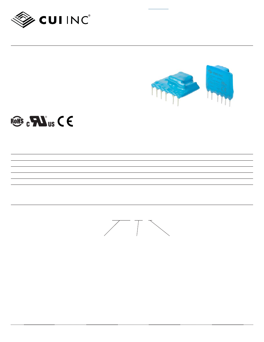
PBK-1
│
DESCRIPTION:
AC-DC POWER SUPPLY
FEATURES
• up to 1 W continuous output
• compact SIP package
• single regulated outputs from 5~24 V
• 3,000 Vac isolation
• over current and short circuit protections
• CE, UL60950-1 safety approval
• wide input voltage: 70~400 Vdc (85~264 Vac)
• efficiency up to 70%
PART NUMBER KEY
PBK-1-
XX - X
Output Voltage
Orientation
“blank” = vertical
B = right-angle
Base Number
MODEL
output
voltage
output
current
output
power
ripple
and noise
1
ef
fi
ciency
(Vdc)
max
(mA)
max
(W)
max
(mVp-p)
typ
(%)
PBK-1-5
5
200
1
120
66
PBK-1-9
9
111
1
120
67
PBK-1-12
12
83
1
120
70
PBK-1-15
15
67
1
120
69
PBK-1-24
24
42
1
120
68
Note:
1. Measured at 20 MHz bandwidth, see Test Con
fi
guration section.
For more information, please visit the