cui
.com
date
03/25/2014
page
1 of 9
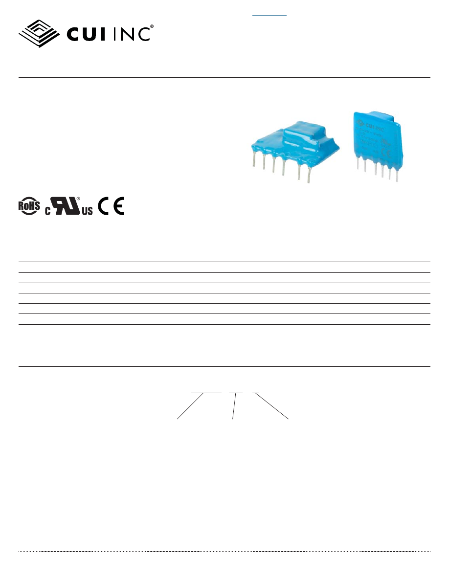
SERIES:
PBK-3
│
DESCRIPTION:
AC-DC POWER SUPPLY
FEATURES
• up to 3 W continuous output
• compact SIP package
• single regulated outputs from 3.3~24 V
• 3,000 Vac isolation
• over current and short circuit protections
• CE, UL60950-1 safety approval
• wide input voltage: 100~400 Vdc (85~264 Vac)
• efficiency up to 78%
PART NUMBER KEY
PBK-3-
XX - X
Output Voltage
Orientation
“blank” = vertical
B = right-angle
Base Number
MODEL
output
voltage
output
current
output
power
ripple
and noise
2
ef
fi
ciency
(Vdc)
max
(mA)
max
(W)
max
(mVp-p)
typ
(%)
PBK-3-3
1
3.3
500
1.65
150
66
PBK-3-5
5
500
2.5
150
69
PBK-3-9
9
333
3
120
76
PBK-3-12
12
250
3
120
78
PBK-3-15
15
200
3
120
78
PBK-3-24
24
125
3
120
78
Note:
1. The PBK-3-3 & PBK-3-3-B do not meet UL and CE standards.
2. Measured at 20 MHz bandwidth, see Test Con
fi
guration section.
For more information, please visit the
product page
.
pbk-3-html.html
cui
.com
date
03/25/2014
│
page
2 of 9
CUI Inc
│
SERIES:
PBK-3
│
DESCRIPTION:
AC-DC POWER SUPPLY
INPUT
parameter
conditions/description
min
typ
max
units
voltage
85
100
264
400
Vac
Vdc
frequency
47
440
Hz
current
at 115 Vac
at 230 Vac
120
60
mA
mA
inrush current
at 115 Vac
at 230 Vac
20
40
A
A
no load power consumption
0.5
W
input fuse
1 A/250 V, slow-blow type (external, required)
OUTPUT
parameter
conditions/description
min
typ
max
units
output current
10
%
capacitive load
3.3 Vdc output models
5 Vdc output models
9 Vdc output models
all other models
2300
470
150
100
μ
F
μ
F
μ
F
μ
F
line regulation
3.3 Vdc models, at full load
all other models, at full load
±0.5
±1.5
%
%
load regulation
3.3 Vdc models, at 10%~100% load
all other models, at 10%~100% load
±1.5
±2.5
%
%
voltage set accuracy
3.3 Vdc output models
9 & 12 Vdc output models
all other models
±3
±8
±5
%
%
%
hold-up time
at 115 Vac
at 230 Vac
60
300
ms
ms
switching frequency
3.3 Vdc output models
all other models
100
50
kHz
kHz
temperature coef
fi
cient
±0.15
%/°C
PROTECTIONS
parameter
conditions/description
min
typ
max
units
short circuit protection
continuous, auto restart
over current protection
auto restart
SAFETY & COMPLIANCE
parameter
conditions/description
min
typ
max
units
isolation voltage
input to output, for 1 minute
3,000
Vac
isolation resistance
100
M
Ω
safety approvals
UL60950-1, CE
safety class
Class II
conducted emissions
CISPR22/EN55022 external circuit required, Class A (see
fi
gure 2); Class B (see
fi
gure 3)
radiated emissions
CISPR22/EN55022 external circuit required, Class A (see
fi
gure 2); Class B (see
fi
gure 3)
ESD
IEC/EN61000-4-2 Class B, contact ±4 kV
radiated immunity
IEC/EN61000-4-3 Class A, 10V/m (external circuit required, see
fi
gure 3)
EFT/burst
IEC/EN61000-4-4 Class B, ±2 kV (external circuit required, see
fi
gure 2)
IEC/EN61000-4-4 Class B, ±4 kV (external circuit required, see
fi
gure 3)
surge
IEC/EN61000-4-5 Class B, ±1 kV/±2 kV (external circuit required, see
fi
gure 3)
conducted immunity
IEC/EN61000-4-6 Class A, 3 Vr.m.s (external circuit required, see
fi
gure 3)
PFM
IEC/EN61000-4-8 Class A, 10 A/m
For more information, please visit the
product page
.
pbk-3-html.html
cui
.com
date
03/25/2014
│
page
3 of 9
CUI Inc
│
SERIES:
PBK-3
│
DESCRIPTION:
AC-DC POWER SUPPLY
Load (%)
Load(%)
PBK-3-5
PBK-3-9
PBK-3-12
PBK-3-15
PBK-3-24
PBK-3-5
PBK-3-9
PBK-3-12
PBK-3-15
PBK-3-24
E
ff
ic
e
n
c
y
(%
)
Ef
fi
c
ie
nc
y
(%
)
25
30
35
40
45
50
55
60
65
70
75
80
10
20
30
40
50
60
70
80
90
100
85VAC
110VAC
230VAC
264VAC
100VDC
200VDC
300VDC
400VDC
55
60
65
70
75
80
85
100
150
200
250
300
350
400
Input Voltage(VDC)
Ef
fi
c
ie
n
cy
(%)
55
60
65
70
75
80
85
85
110
120
220
230
240
264
Input Voltage(VAC)
E
ff
ic
ie
n
cy(
%
)
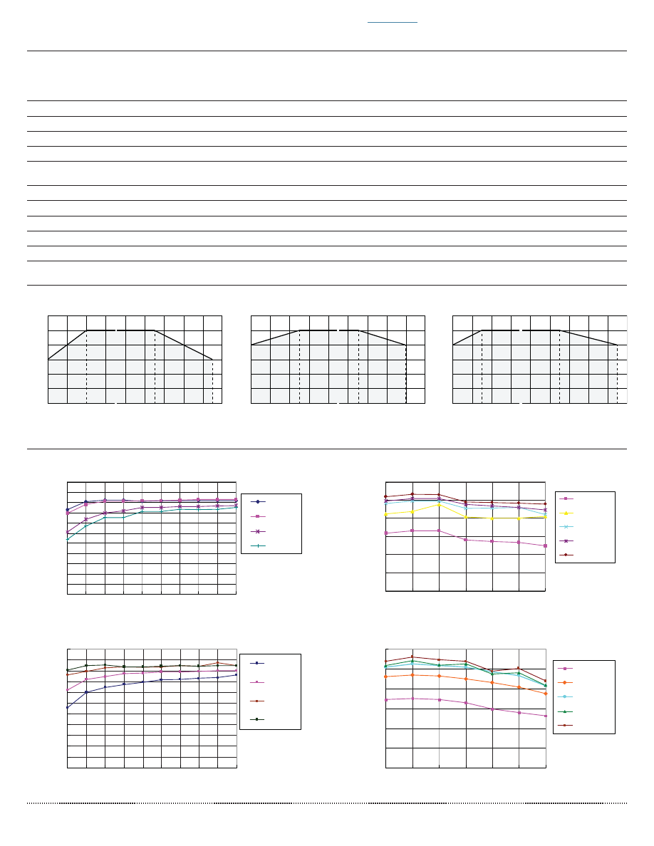
EFFICIENCY CURVES
~ ~
~ ~
~ ~
~ ~
100
80
60
40
20
Ambient Temperature (°C)
Load (%)
-30
-40
40
50 55
-20
-10
70
60
80 85 90
Safe operating area
~ ~
100
80
60
40
20
Input Voltage (Vac)
Load (%)
85
95
105
115
125
110
235
245
240
255
264
Safe operating area
~ ~
100
80
60
40
20
Input Voltage (Vdc)
Load (%)
50
70
90 100 110
130
310
330
350
340
370
390400
Safe operating area
load vs. ambient temperature
(at 110~240 Vac input voltage)
ef
fi
eciency vs. load
PBK-3-12
ef
fi
eciency vs. load
PBK-3-12
ef
fi
eciency vs. input voltage (full load)
ef
fi
eciency vs. input voltage (full load)
load vs. input voltage (Vac)
(at 25°C)
load vs. input voltage (Vdc)
(at 25°C)
SAFETY & COMPLIANCE (CONTINUED)
parameter
conditions/description
min
typ
max
units
voltage dips & interruptions
IEC/EN61000-4-11 Class B, 0%-70%
MTBF
at 25°C, max. load
300,000
hours
RoHS
2011/65/EU
ENVIRONMENTAL
parameter
conditions/description
min
typ
max
units
operating temperature
see derating curves
-40
85
°C
storage temperature
-40
105
°C
case temperature
90
°C
humidity
non-condensing
85
%
DERATING CURVES
For more information, please visit the
product page
.
pbk-3-html.html
cui
.com
date
03/25/2014
│
page
4 of 9
CUI Inc
│
SERIES:
PBK-3
│
DESCRIPTION:
AC-DC POWER SUPPLY
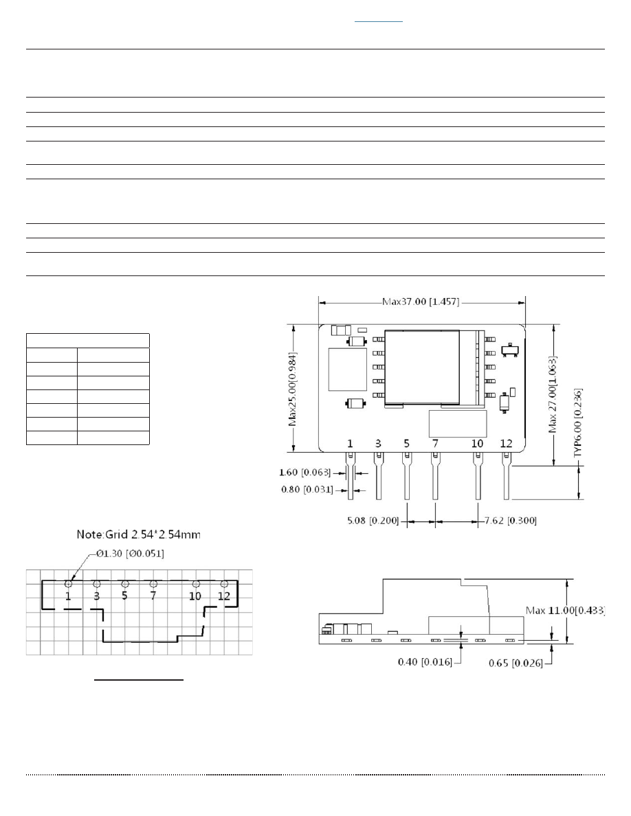
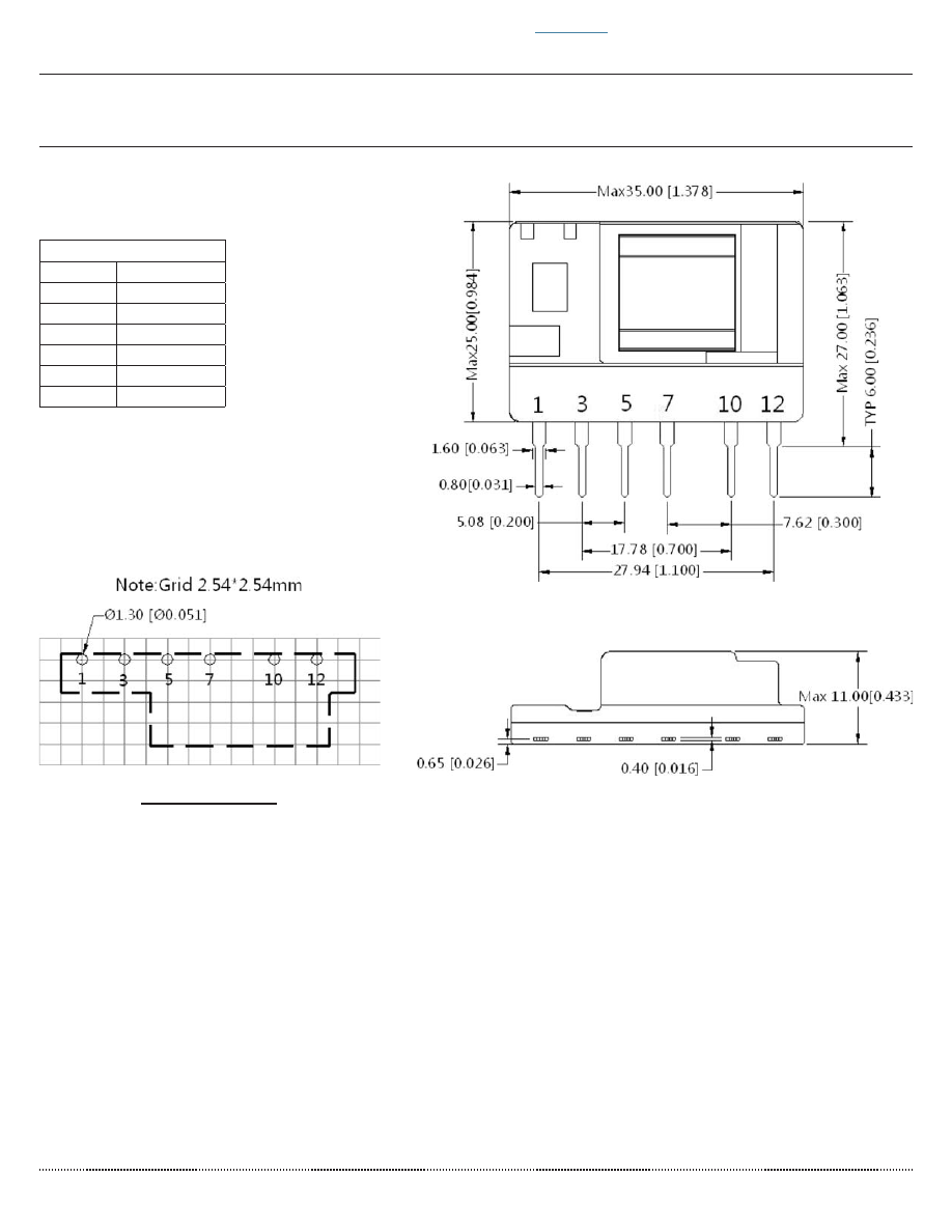
Front View
Top View
PCB Layout
Bottom View
SOLDERABILITY
parameter
conditions/description
min
typ
max
units
hand soldering
for 3~5 seconds
350
360
370
°C
wave soldering
for 5~10 seconds
255
260
265
°C
MECHANICAL
parameter
conditions/description
min
typ
max
units
dimensions
PBK-3-3 vertical model: 37 x 11 x 25
all other vertical models: 35 x 11 x 25
PBK-3-3 right-angle model: 37 x 13 x 25
all other right-angle models: 35 x 13 x 25
mm
mm
mm
mm
material
UL94V-0
weight
8
g
MECHANICAL DRAWING
units: mm[inch]
tolerance: ±0.5[±0.020]
pin tolerance: ±0.1[±0.004]
PBK-3-3 VERTICAL ORIENTATION
PIN CONNECTIONS
PIN
FUNCTION
1
-Vin (N)
3
+Vin (L)
5
+V(CAP)
7
-V(CAP)
10
-Vo
12
+Vo
Note: 1. It is required to add C1 between
pins 5 & 7 (see application circuits).
For more information, please visit the
product page
.
pbk-3-html.html
cui
.com
date
03/25/2014
│
page
5 of 9
CUI Inc
│
SERIES:
PBK-3
│
DESCRIPTION:
AC-DC POWER SUPPLY
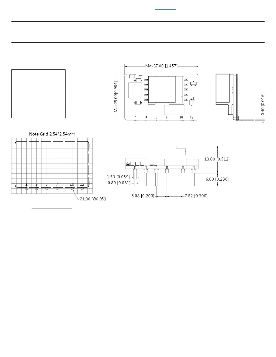
Front View
Top View
PCB Layout
Bottom View
MECHANICAL DRAWING (CONTINUED)
units: mm[inch]
tolerance: ±0.5[±0.020]
pin tolerance: ±0.1[±0.004]
VERTICAL ORIENTATION (ALL OTHER MODELS)
PIN CONNECTIONS
PIN
FUNCTION
1
-Vin (N)
3
+Vin (L)
5
+V(CAP)
7
-V(CAP)
10
-Vo
12
+Vo
Note: 1. It is required to add C1 between
pins 5 & 7 (see application circuits).
For more information, please visit the
product page
.
pbk-3-html.html
cui
.com
date
03/25/2014
│
page
6 of 9
CUI Inc
│
SERIES:
PBK-3
│
DESCRIPTION:
AC-DC POWER SUPPLY
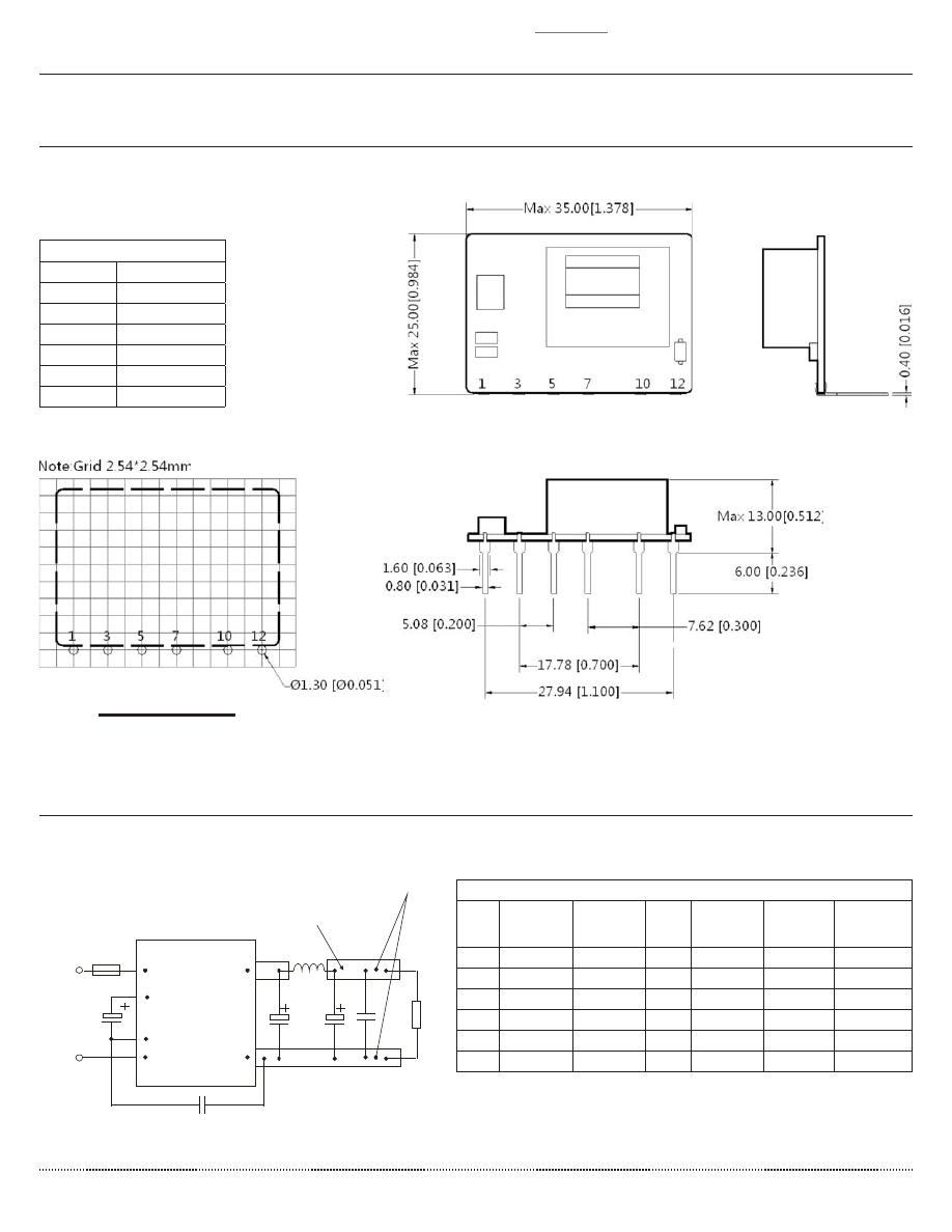
Front View
Top View
PCB Layout
Bottom View
Side View
MECHANICAL DRAWING (CONTINUED)
units: mm[inch]
tolerance: ±0.5[±0.020]
pin tolerance: ±0.1[±0.004]
PBK-3-3 RIGHT-ANGLE ORIENTATION
PIN CONNECTIONS
PIN
FUNCTION
1
-Vin (N)
3
+Vin (L)
5
+V(CAP)
7
-V(CAP)
10
-Vo
12
+Vo
Note: 1. It is required to add C1 between
pins 5 & 7 (see application circuits).
For more information, please visit the
product page
.
pbk-3-html.html
cui
.com
date
03/25/2014
│
page
7 of 9
CUI Inc
│
SERIES:
PBK-3
│
DESCRIPTION:
AC-DC POWER SUPPLY
TEST CONFIGURATION
Figure 1
Table 1
Recommended External Circuit Components
V
OUT
(Vdc)
C1
1
C2
1
L1
1
C3
1
C4
CY0
(Y1
capacitor)
3.3
22
μ
F/400V 330
μ
F/25V 2.2
μ
H 120
μ
F/25V 0.1
μ
F/50V 1nF/400Vac
5
22
μ
F/400V 330
μ
F/25V 2.2
μ
H
68
μ
F/35V
0.1
μ
F/50V 1nF/400Vac
9
22
μ
F/400V 330
μ
F/25V 2.2
μ
H
68
μ
F/35V
0.1
μ
F/50V 1nF/400Vac
12
22
μ
F/400V 150
μ
F/35V 2.2
μ
H
68
μ
F/35V
0.1
μ
F/50V 1nF/400Vac
15
22
μ
F/400V 150
μ
F/35V 2.2
μ
H
68
μ
F/35V
0.1
μ
F/50V 1nF/400Vac
24
22
μ
F/400V 100
μ
F/35V 2.2
μ
H
68
μ
F/35V
0.1
μ
F/50V 1nF/400Vac
C o p p e r s h e e t
Lo
ad
C o n n e c t Os c illo g r a p h P ro b e
$&
/
$&
1
AC -D C
+Vo
-Vo
F U SE
C 2
C 3
C Y 0
L 1
C 4
C 1
Note:
1. Required components.
2. 1 A/250 V fuse required.
Front View
Top View
PCB Layout
Bottom View
Side View
MECHANICAL DRAWING (CONTINUED)
units: mm[inch]
tolerance: ±0.5[±0.020]
pin tolerance: ±0.1[±0.004]
RIGHT-ANGLE ORIENTATION (ALL OTHER MODELS)
PIN CONNECTIONS
PIN
FUNCTION
1
-Vin (N)
3
+Vin (L)
5
+V(CAP)
7
-V(CAP)
10
-Vo
12
+Vo
Note: 1. It is required to add C1 between
pins 5 & 7 (see application circuits).
For more information, please visit the
product page
.
pbk-3-html.html
cui
.com
date
03/25/2014
│
page
8 of 9
CUI Inc
│
SERIES:
PBK-3
│
DESCRIPTION:
AC-DC POWER SUPPLY
EMC RECOMMENDED CIRCUIT
Recommended External Circuit Components
MOV2
S10K300
CY1, CY2
1nF/400Vac
CX
0.1
μ
F/275Vac
LCM
3.5mH
LDM
5mH
FUSE
1A/250V, slow blow
Figure 3
Table 3
AC ( N )
AC ( L)
A C (L )
M O V 2
LC M
C X
CY 1
CY 2
AC-DC
C 1
+
5
F U SE
12
C Y 0
10
7
AC ( N )
-V o
+V o
L1
+
+
C 2
C 3
T V S
R L
C 4
LD M
Notes:
1. C1 and C3 are electrolytic capacitors. They are required for both AC input and DC input.
2. For AC input, C1 is used as a
fi
lter capacitor. The recommended C1 value is 22
μ
F/400 V.
3. For DC input, C1 is used as an EMC
fi
lter capacitor. The recommended C1 value is 10
μ
F/400V. When the input voltage is above 370VDC, we recommend a 10
μ
F/450V capacitor.
4. C2 and C3 are output
fi
ler capacitors, we recommend high frequency and low impedance electrolytic capacitors. For capacitance and rated ripple current of capacitors refer to
the datasheets provided by the manufacturers, voltage derating of capacitors should be 80% or above.
5. C4 is a ceramic capacitor which is used to
fi
lter high frequency noise. C2, C3 and L1 form a pi-type
fi
lter circuit. For current of L1 and L2 refer to the datasheets provided by
the manufacturers, current derating should be 80% or above. TVS is a recommended component to protect post-circuits (if converter fails). We recommend using a 5D-9
external input NTC.
6. For standard EMC requirements, please refer to
fi
gure 2. If a higher EMC is required, please refer to
fi
gure 3.
7. All speci
fi
cations measured at Ta=25C, humidity <75%, 115 Vac & 230 Vac input voltage, and rated output load, unless otherwise speci
fi
ed.
Note:
Also refer to Table 2.
TYPICAL APPLICATION CIRCUIT
1
+Vo
-Vo
10
12
AC( L)
AC(N)
C1
+
5
3
) 8 6 (
1 7 &
MOV1
7
A C-DC
C2
C3 TVS
RL
+
L1
(1)
+
C4
L2
CY0
Note: (1) is Pi filter circuit.
Figure 2
Table 2
Recommended External Circuit Components
V
OUT
(Vdc)
C1
1
L2
C2
1
L1
1
C3
1
C4
CY0
FUSE
1
TVS
NTC
MOV1
3.3
22
μ
F/400V 5mH 330
μ
F/25V 2.2
μ
H 120
μ
F/25V 0.1
μ
F/50V 1nF/400Vac
1A/250V
SMBJ7.0A
5D-9
S14K350
5
22
μ
F/400V 5mH 330
μ
F/25V 2.2
μ
H
68
μ
F/35V
0.1
μ
F/50V 1nF/400Vac
1A/250V
SMBJ7.0A
5D-9
S14K350
9
22
μ
F/400V 5mH 330
μ
F/25V 2.2
μ
H
68
μ
F/35V
0.1
μ
F/50V 1nF/400Vac
1A/250V
SMBJ12A
5D-9
S14K350
12
22
μ
F/400V 5mH 150
μ
F/35V 2.2
μ
H
68
μ
F/35V
0.1
μ
F/50V 1nF/400Vac
1A/250V
SMBJ20A
5D-9
S14K350
15
22
μ
F/400V 5mH 150
μ
F/35V 2.2
μ
H
68
μ
F/35V
0.1
μ
F/50V 1nF/400Vac
1A/250V
SMBJ20A
5D-9
S14K350
24
22
μ
F/400V 5mH 100
μ
F/35V 2.2
μ
H
68
μ
F/35V
0.1
μ
F/50V 1nF/400Vac
1A/250V
SMBJ30A
5D-9
S14K350
Note:
1. Required components.
For more information, please visit the
product page
.
pbk-3-html.html
date
03/25/2014
│
page
9 of 9
CUI Inc
│
SERIES:
PBK-3
│
DESCRIPTION:
AC-DC POWER SUPPLY
CUI offers a two (2) year limited warranty. Complete warranty information is listed on our website.
CUI reserves the right to make changes to the product at any time without notice. Information provided by CUI is believed to be accurate and reliable. However, no responsibility is
assumed by CUI for its use, nor for any infringements of patents or other rights of third parties which may result from its use.
CUI products are not authorized or warranted for use as critical components in equipment that requires an extremely high level of reliability. A critical component is any component of a
life support device or system whose failure to perform can be reasonably expected to cause the failure of the life support device or system, or to affect its safety or effectiveness.
Headquarters
20050 SW 112th Ave.
Tualatin, OR 97062
800.275.4899
Fax 503.612.2383
cui
.com
techsupport@cui.com
rev.
description
date
1.0
initial release
08/09/2013
1.01
added 3.3 Vdc output model, added bent pin model options, updated
emc recommendations
03/25/2014
The revision history provided is for informational purposes only and is believed to be accurate.
REVISION HISTORY
For more information, please visit the
product page
.