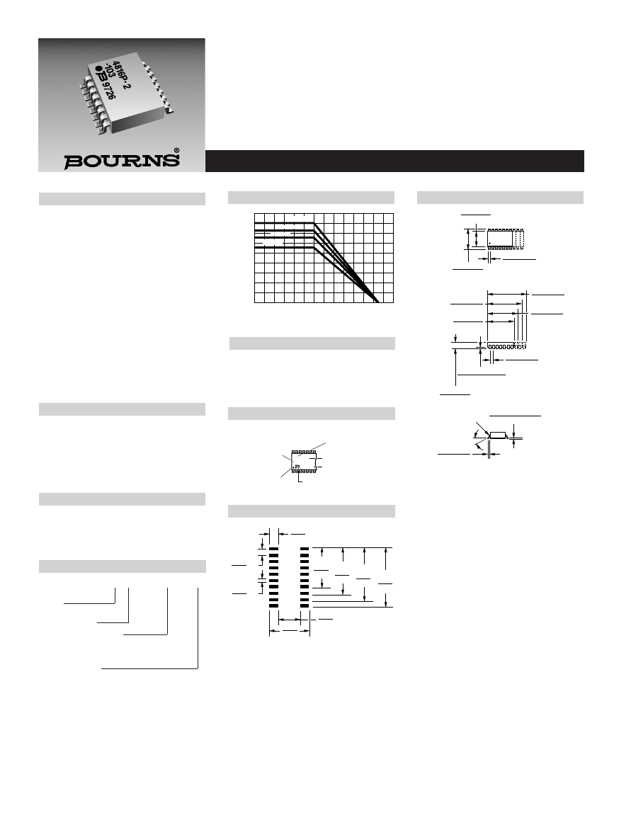
Package Power Temp. Derating Curve
4800P Series - Thick Film Surface Mounted Medium Body
Specifications are subject to change without notice.
Product Characteristics
Resistance Range
.....................10 ohms to 2.2 megohms
Maximum Operating Voltage.............50V
Temperature Coefficient of Resistance
50
Ω
and above.................±100ppm/°C
below 50
Ω
........................±250ppm/°C
TCR Tracking
...............50ppm/°C max.; equal values
100ppm/°C 50W and above
Operating Temperature
...................................-55°C to +125°C
Insulation Resistance
..........................10,000 megohms min.
Dielectric Withstanding Voltage
.............................................200 VRMS
Lead Solderability
.....Meet requirements of MIL-STD-202
Method 208
Environmental Characteristics
TESTS PER MIL-STD-202 ........
∆
R MAX.
Short Time Overload...................±0.25%
Load Life .....................................±1.00%
Moisture Resistance ...................±0.50%
Resistance to Soldering Heat .....±0.25%
Thermal Shock............................±0.25%
Physical Characteristics
Flammability .........Conforms to UL94V-0
Lead Frame Material
..........................Copper, solder coated
Body Material ..................Novolac epoxy
WATTS
AMBIENT TEMPERATURE ( C )
°
0
70
125
1.6
1.4
1.2
1.0
.8
.6
.4
.2
25
4814P
4816P
4818P
4820P
Package Power Rating at 70°C
4814P......................................1.12 watts
4816P......................................1.28 watts
4818P......................................1.44 watts
4820P......................................1.60 watts
5.59
±
.12
(.220
±
.005)
7.62
±
.25
(.300
±
.010)
.432
±
.076
(.017
±
.003)
9.91
±
.12
(.390
±
.005)
12.45
±
.12
(.490
±
.005)
11.18
±
.12
(.440
±
.005)
13.72
±
.12
(.540
±
.005)
.13 + .12/ - .00
(.005 + .005/ - .000)
2.03
±
.12
(.080
±
.005)
.611
±
.101
(.024
±
.004)
R = .008" TYP.
8
°
MAX.
Lead coplanarity .102mm (.004 inch) max. at mounting surface.
Governing dimensions are in metric. Dimensions in parentheses
are inches and are approximate.
*Terminal centerline to centerline measurements made at point of
emergence of the lead from the body.
TYP.
1.27
±
.076
(.050
±
.003*)
TYP.
.305 + .000/ - .101
(.012 + .000/ - .004)
PART NUMBER
-330
4816P-1
YYWW
RESISTANCE
CODE
DATE CODE
CIRCUIT
MANUFACTURER'S
TRADEMARK
PIN ONE
INDICATOR
Represents total content. Layout may vary.
How To Order
48 16 P - 1 - 103
Model
(48 = SOM Pkg)
Number of Pins
Electrical Configuration
• 1 or 4 = Isolated*
• 2 = Bussed*
• 3 = Dual Terminator*
Resistance Code
• First 2 digits are significant
• Third digit represents the
number of zeros to follow.
*For tube packaging, use T01, T02, T03 or T04.
Consult factory for other available options.
1
20
2
19
3
18
4
17
5
16
6
15
7
14
8
13
9
12
10
11
SOM-14
SOM-16
SOM-18
SOM-20
NOTE: Land pattern dimensions are based on
design rules established by the Institute for Inter-
connecting and Packaging Electronic Circuits in
IPC-SM-782.
TYP.
1.27
(.050)
8.26
(.325)
9.53
(.375)
10.80
(.425)
12.07
(.475)
4.9
(.193)
8.9
(.350)
TYP.
2.0
(.079)
TYP.
.63
(.025)
Product Dimensions
Typical Part Marking
Recommended Land Pattern
Features
■
Standard E.I.A. package compatible with
automatic placement equipment
■
Tape and reel packaging standard
(see page 304 for dimensions)
■
For ordering guidelines, see page 304
■
Marking on contrasting background for
permanent identification
■
Compliant leads to reduce solder joint
fatiguing
■
Standard electrical schematics: isolated,
bussed, dual terminator
■
Custom circuits are available