INDEX
QUICK PRODUCT
LOCATOR
PEM® brand fasteners utilize self-clinching,
broaching, flaring, surface mount, bonding
or weld technology to provide strong,
reusable, and permanent threads and
mounting points in thin sheet metal, P.C.
board or other rigid materials.
Bulletin INDEX-118
pem-html.html
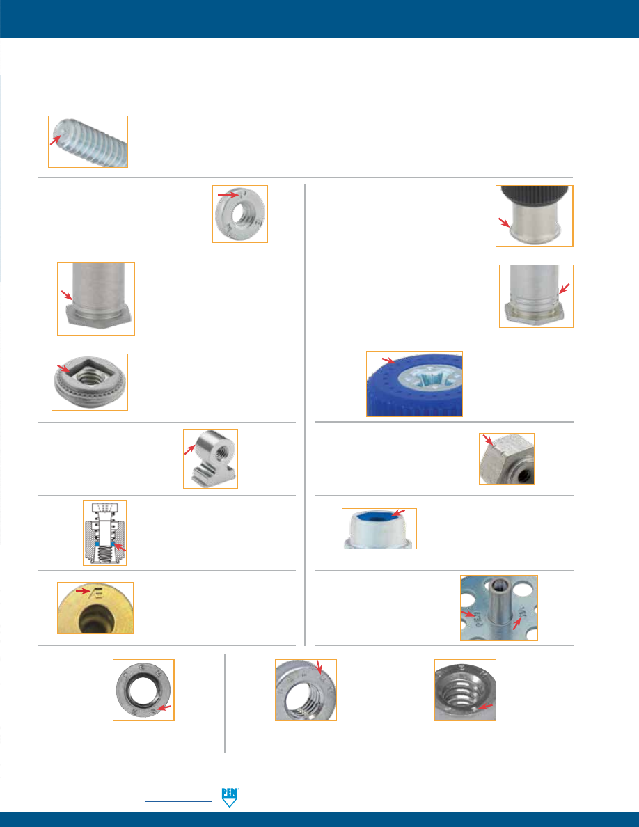
To help you identify genuine PEM® brand fasteners, most are marked by one of our trademarks or identifiers. Genuine PEM fasteners can only be
purchased from one of our authorized worldwide distributors. For a complete listing of these distributors, check our web site:
www.pemnet.com.
PEM® FASTENER IDENTIFICATION MARKS
Trademark ATLAS® AE Stamp
MaxTite® and Plus+Tite® products
Trademark PEM® Skirted Shoulder
PF11, PF11M, PF11MF, PF11MW, PF11PM,
PF12, PF12M, PF12MF,
PF12MW, PF7M, and PF7MF fasteners
Trademark
PEM® C.A.P.S.®
Dot Pattern
PF11PM fastener
Trademark PEM® Dimple
CFHA, CFHC, CHA, CHC, FH, FH4, FHA, FHL, FHLS, FHP, FHS, FHX, HF109, HFG8, HFE, HFH,
HFHB, HFHS, HFLH, HSCB, KFH, KSSB, MPP, PF10, PF30, PF31, PF32, PF50, PF51, PF52, PF60, PF61,
PF62, PF11, PF11M, PF11MF, PF11MW, PF11PM, PF12, PF12M, PF12MF, PF12MW, PF7M, PF7MF, PFC2,
PFC2P, PFC4, PFHV, PFK, PFS2, PSHP, SCB, SCBJ, SCBR, SF, SFK, SFP, SFW, SGPC, SKC, SKC-F,
SMTPFLSM, SSA, SSC, SSS, T, T4, TFH, TFHS, THFE, TK4, TKA, TP4, TPS, TPXS, and TS fasteners
Trademark PEM®
“Single Groove”
A4, BSO4, LA4, MSO4, PFC4,
SO4, SP (Select sizes), and
TSO4 fasteners
Trademark PEM®
“Two Groove”
B, BS, BSO, BSON, BSOS, CSOS, CSS,
DSO, DSOS, HSR, KF2, KFB3, KFE, KFS2,
KFSE, PF7M, PF7MF, SMTSO, SMTSOB,
SMTPFLSM, SO, SOA, SOAG, SON, SOS,
SOSG, TSO, TSOA, and TSOS fasteners
Trademark PEM®
“Double Squares”
A4, AC, AS, LA4, LAC, and LAS
fasteners
Trademark PEM® Blue Nylon
Locking Element
PL, PLC and CFN fasteners
Trademark PEM®
Circle on Pedestal
RAS fastener
Trademark PEM® Double Notch
microPEM® SMTSO fastener
Trademark PEM® Stamp
CLS, CLSS, H, HN, HNL, PSHP,
S, SFN, SL, SMPP, SMPS, SS,
and WN fasteners
Trademark PEM
VM® Stamp
(Both Sides)
VariMount™ Base Plates
Trademark PEM® SP Stamp
SP fasteners
Trademark PEM® SH Stamp
SH fasteners
PEM® Blue Nylon Ring
PFC4, PFC2P, PFC2, PFS2,
and PFK fasteners
PEM® RT Stamp
S-RT fasteners
INDEX-2
PennEngineering •
www.pemnet.com
pem-html.html
HFH, HFHB, HFHS
Bulletin FH
Studs for high-strength applications with high pull through
resistance.
Nuts with load-bearing, non-locking threads that permits up
to .030”/0.76mm adjustment for mating hole misalignment.
A4, AC, AS
Bulletin ALA
B, BS
Bulletin B
Nuts used in applications requiring closed thread ends. Blind
end limits screw penetration and excludes foreign matter.
BSO, BSO4, BSOA, BSOS
Bulletin SO
Blind threaded standoffs installed with their heads flush with
one surface of the mounting sheets.
CFN
Bulletin LN
Broaching, nylon insert, self-locking nuts for use in thinner
sheet, close-to-edge applications.
CFHA, CFHC, CHA, CHC
Bulletin CH
Concealed-head studs installed into a blind milled hole where
surface opposite stud must remain unmarred.
CLA, CLS, CLSS
Bulletin CL
Nuts that provide load-bearing threads in thin sheets with
high pushout and torque-out resistances.
CSOS, CSS
Bulletin CH
Concealed-head standoffs installed into a blind milled hole
where surface opposite standoff must remain unmarred.
DSO, DSOS
Bulletin SO
Threaded standoffs for use in close-to-edge applications.
F, F4
Bulletin F
PEMSERT® flush fasteners are flush with both sides of the
sheet.
FE, FEO, FEOX, FEX
Bulletin FE
Miniature nuts with strong threads. Available with locking or
non-locking threads.
FH, FH4, FHA, FHP, FHS
Bulletin FH
Flush-head studs with high pushout and torque-out
resistances.
FHL, FHLS
Bulletin FH
Low-displacement head studs can be installed close to the
edge of a sheet without causing the edge to bulge.
H, HNL
Bulletin CL
Nuts with self-locking or non-locking threads that provide
high pushout and torque-out resistances.
HFE
Bulletin FH
Studs designed with an enlarged head diameter to provide
high-strength in thin sheets.
SC
HF109
Bulletin FH
Property class 10.9 high tensile strength studs meeting 1040
MPa minimum.
HFG8
Bulletin FH
Grade 8 high tensile strength studs meeting 150 ksi minimum.
FHX
Bulletin FH
Flush-head studs with X-Press™ thread profile are typically
used with push-on or other plastic fasteners.
PennEngineering •
www.pemnet.com
INDEX-3
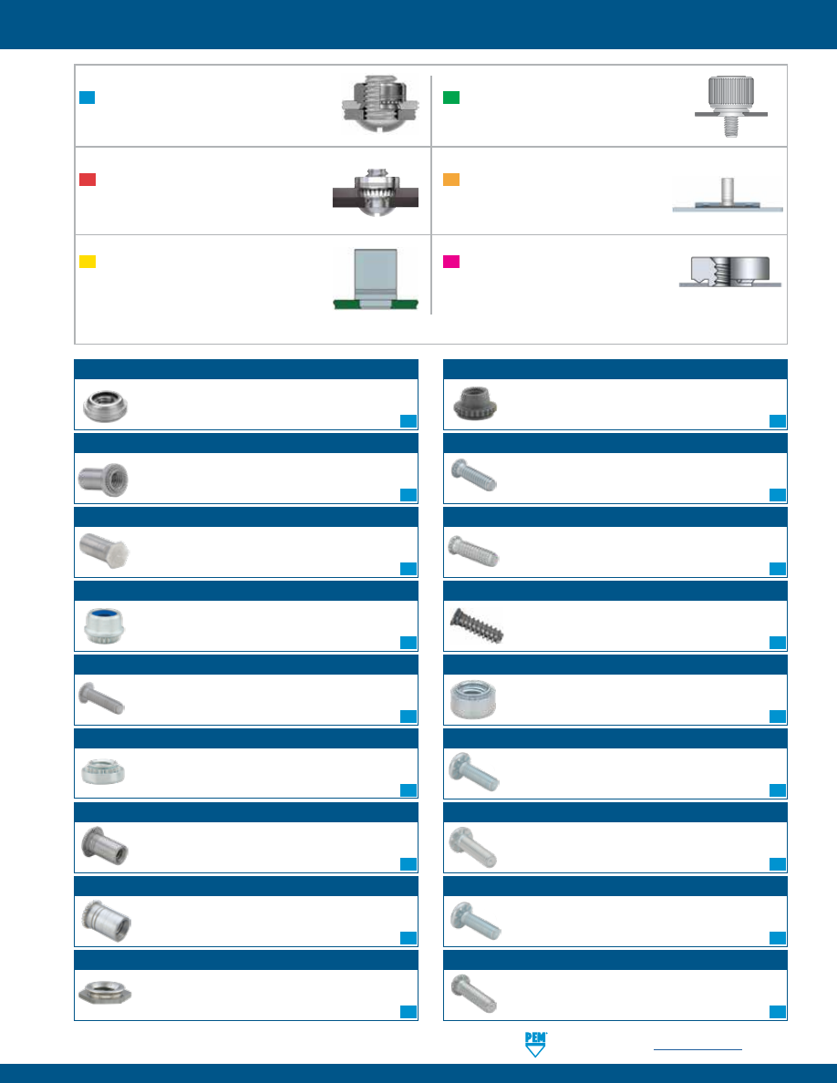
Self-clinching
fasteners are pressed into sheet
metal panels as this as .016” / 0.4 mm.
Broaching
fasteners are pressed into
P.C. board or other plastic materials
as thin as .060” / 1.53 mm.
Surface Mounted
fasteners on tape and reel
are soldered to a PC board in the same way
as other surface mount components.
Flare Mounted
fasteners can be installed into
almost any rigid type of panel.
VariMount® bonding fasteners
are assemblies
comprised of a standard PEM fastener
mounted permanently into base plates.
Weld
nuts are designed specially to be
welded into place.
(
Products are listed alphabetically by type. Refer to matching color square for mounting style)
B
SM
FM
VM
W
SC
SC
SC
SC
SC
SC
SC
SC
SC
SC
SC
SC
SC
SC
SC
SC
SC
SC
pem-html.html
PF11, PF11M
Bulletin PF
Panel fastener assembly with knurled cap and universal slot/
Phillips recess. Available with anti cross-thread feature.
PF12, PF12M
Bulletin PF
Panel fastener assembly with smooth cap and universal slot/
Phillips recess. Available with anti cross-thread feature.
PF30, PF31, PF32
Bulletin PF
Low-profile panel fastener assembly with large knurled head
for tool or hand operation.
PF50
Bulletin PF
Low-profile panel fastener assembly with large knurled cap
and Phillips recess for tool or hand operation.
PF60
Bulletin PF
Low-profile panel fastener assembly with large smooth cap
and Phillips recess for tool or hand operation.
PF11MF
Bulletin PF
Flare-mounted captive screw assembly with anti cross-
thread feature.
PF12MF
Bulletin PF
Flare-mounted captive screw assembly with anti cross-
thread feature.
PEM C.A.P.S.®
Bulletin PF
Colored Access Panel Screws with plastic cap. Key features
include Phillips drive and MAThread® anti-cross threading
feature.
MPP
Bulletin MPF
microPEM® pins that can be installed into sheets as thin as
0.5 mm.
MSO4
Bulletin MPF
microPEM® standoffs that can be installed into sheets as thin
as .016” / 0.4 mm.
PF10
Bulletin PF
Flush-mounted panel screw components.
N10 (nut), PR10 (retainer) and PS10 (screw).
PR10
N10
PS10
PF11MW
Bulletin PF
Floating captive screw assembly allows for mating hole
misalignment.
PF12MW
Bulletin PF
Floating captive screw assembly allows for mating hole
misalignment.
PF7M
Bulletin PF
Small, compact, and low-profile self-clinching captive panel
screws designed for limited access areas.
PF7MF
Bulletin PF
Small, compact, and low-profile flaring captive panel screws
designed for limited access areas.
MSIB
Bulletin MPF
microPEM® symmetrical designed thru-threaded inserts for
plastics for use in straight or tapered holes.
LA4, LAC, LAS
Bulletins ALA & LN
Nuts with load-bearing, self-locking threads that permits up
to .030” / 0.76 mm adjustment for mating hole misalignment.
LK, LKA, LKS
Bulletin LN
Nuts with a unique PEMFLEX® self-locking feature permitting
repeated use and effective prevailing locking torque.
KF2, KFS2
Bulletin K
Nuts, internally threaded, for mounting on P.C. boards.
KFB3
Bulletin K
Flare-mounted standoffs for mounting on P.C. boards with
greater pullout performance.
KFE, KFSE
Bulletin K
Threaded or unthreaded standoffs mounted on P.C. boards for
stacking or spacing.
KFH
Bulletin K
Threaded studs for use as solderable connectors or as
permanently mounted studs on P.C. boards.
KSSB
Bulletins K & SSA
SNAP-TOP® standoffs featuring a spring action to hold a P.C.
Board securely without screws or threaded hardware.
HSCB
Bulletin PF
Heat sink mounting system.
HSCB (screw), HSR (nut) and HSL (spring).
HSCB
HSR
HSL
HFLH
Bulletin FH
Studs are for installation into thin, harder, high-strength
materials.
PennEngineering •
www.pemnet.com
INDEX-4
MSOFS
Bulletin MPF
microPEM® flaring standoffs attached permanently in panels
as thin as .008” / 0.2 mm of any hardness including stainless
steel.
B
B
SC
SC
SC
SC
Inserts
SC
FM
SC
SC
B
B
B
FM
SC
FM
FM
SC
SC
SC
SC
FM
FM
SC
FM
SC
SC
pem-html.html
FM
PL, PLC
Bulletin LN
PEMHEX® self-locking nuts with a nylon hexagonal element to
provide a reusable prevailing torque thread lock.
PSL2, PTL2
Bulletin PF
Spring-loaded plunger assembly. Quick lockout feature on
Type PTL2 holds plunger in retracted position.
RAA
Bulletin RA
Self-tapping R’ANGLE® fasteners provide strong right angle
attachment points in thin sheets.
PFC2, PFS2
Bulletin PF
Spring-loaded panel fastener assembly for tool or hand
operation.
PFC2P
Bulletin PF
Panel fastener assembly with Phillips recess for tool only
operation.
PFHV
Bulletin PF
Low-cost panel fastener assembly with universal slot/Phillips
recess for tool or hand operation.
PFK
Bulletins K & PF
Panel fastener assembly for mounting on P.C. boards.
SL
Bulletins CL & LN
Locknuts designed with a unique TRI-DENT® locking feature,
which meets demanding locking performance requirements.
SMPS, SMPP
Bulletin CL
Nuts that feature a lower profile and can be mounted closer to
the edge of a sheet than standard self-clinching nuts.
RAS
Bulletin RA
Threaded R’ANGLE® fasteners provide strong right angle
attachment points in thin sheets.
S, SS
Bulletin CL
Nuts that provide load-bearing threads in thin sheets with
high pushout and torque-out resistances.
SCB
Bulletin PF
The spinning clinch bolt with axial float installs captive in
panel and still spins freely.
SF, SFP
Bulletin SF
SpotFast® self-clinching fasteners create a permanent, flush
joining of two sheets of metal.
SKC
Bulletin SK
KEYHOLE® standoffs designed for a board to be quickly slipped
into place and removed by sliding it sideways and lifting it off.
SKC-F
Bulletin SK
KEYHOLE® sheet joining fasteners designed to quickly join
two sheets flat against each other and then can be removed.
SFW
Bulletin SF
SpotFast® self-clinching fasteners create a permanent, flush
joining of two sheets of metal. The washer allows for consistent
pivoting of the two metal panels.
SFK
Bulletin SF
SpotFast® self-clinching fasteners create a permanent, flush
joining of metal to PCB or plastic panels.
PFC4
Bulletin PF & SS
Panel fastener assembly for installation into stainless steel
sheets with Phillips recess for tool only operation.
PSHP
Bulletin K
Surface mount panel fastener screw that is used with Type
SMTPR retainer.
SCBJ
Bulletin PF
The spinning clinch bolt with jacking feature installs captive
in panel and still spins freely.
SGPC
Bulletin FH
Install into most panel material, provide strong torque-out
resistance and are suitable for close centerline-to-edge
situations.
SCBR
Bulletin PF
The spinning clinch bolt with axial float utilizes self-retracting
spring.
SFN
Bulletin SFN
Spinning flare nut is a one-piece, flanged hex nut that is
permanently captive and still spins freely in the sheet.
SH
Bulletin CL
Nuts are for installation into thin, harder, high-strength
materials.
SMTPFLSM
Bulletin K
Surface mount spring-loaded captive panel screws.
PennEngineering •
www.pemnet.com
INDEX-5
S-RT
Bulletin CL
Free-running locknuts with a thread form that creates a lock
when clamp load is applied.
B
SC
SM
SC
SC
SC
SC
SC
SC
SC
SC
SC
SC
SC
SC
SC
SC
SC
SC
SM
SC
SC
B
SC
FM
SC
pem-html.html
SMTRA
Bulletin K
Surface mount R’ANGLE® fasteners provide strong re-usable
threads at right angle to PC board.
SMTSO, SMTSOB
Bulletin K
Surface mount spacers and nuts are available threaded and
unthreaded.
TPS, TP4
Bulletin FH
Flush-mounted pilot pins with chamfered end to make mating
hole location easy.
TPXS
Bulletin FH
Alignment pin for ATCA® faceplate fastening solutions.
TSO, TSOA, TSOS
Bulletin SO
Standoffs provide permanent threads in ultra-thin sheets.
SO, SO4, SOA, SOS
Bulletin SO
Thru-hole threaded and unthreaded standoffs installed with
their heads flush with one surface of the mounting sheets.
SOAG, SOSG
Bulletin SO
Grounding standoffs for clinching into metal chassis with
“gripping teeth” at opposite end to firmly contact mating
board.
SP
Bulletins CL & SS
Specially hardened self-clinching nuts for installation into
stainless steel sheets.
SSA, SSC, SSS
Bulletin SSA
SNAP-TOP® standoffs featuring a spring action to hold a P.C.
board securely without screws or threaded hardware.
TD
Bulletin TD
TY-D® self-clinching tie-mounts provide secure attachment
points for mounting wires to electronic chassis or enclosure.
TDO
Bulletin TD
TY-D® self-clinching hooks enable users to easily attach,
remove, and return tie-bundled wires to their mounting
points.
TFH, TFHS
Bulletin FH
Non-flush studs for sheets as thin as .020” / 0.51 mm.
SMTPR
Bulletin K
Surface mount panel fastener retainer that is used with Type
PSHP screw.
T, T4
Bulletin MPF
microPEM® TackPin® fasteners for compact electronic
assemblies enable sheet-to-sheet attachment.
TSO4
Bulletin SO
Standoffs for installation into ultra-thin stainless steel sheets
as thin as .025” / 0.63 mm.
TK4, TKA
Bulletin MPF
microPEM® TackSert® pins designed to hold a top panel to a
bottom panel by broaching into the bottom panel.
THFE
Bulletin FH
Heavy-duty studs for sheets as thin as .031” / 0.8 mm.
U, UL
Bulletin FE
Miniature nuts with strong threads. Available with locking or
non-locking threads.
WN, WNS
Bulletin WN
Self-locating projection weld nuts. The engineered
projections prevent burn-outs in thin sheets.
TS
Bulletin MPF
TackScrew® fasteners enable cost-effective sheet-to-sheet
attachment by simply pressing into place. Can be removed
by simply unscrewing.
VM
Bulletin VM
The PEM® VariMount® bonding fasteners are assemblies
comprised of a standard PEM fastener mounted permanently
into base plates.
PennEngineering •
www.pemnet.com
INDEX-6
SMTSS
Bulletin K
Surface mount standoffs that eliminate the need for attaching
screws.
SC
SC
SC
SC
SC
SC
SC
SM
SM
SM
SM
SC
SC
SC
SC
VM
W
SC
B
SC
SC
SC
pem-html.html
“Dos”
Do
provide mounting hole of specified size for each fastener.
Do
install fastener into punch side of sheet.
Do
make certain that shank (or pilot) is within hole before applying installation force.
Do
apply squeezing force between parallel surfaces.
Do
apply sufficient force to totally embed clinching ring around entire circumference and to bring shoulder squarely in contact with
sheet. For some fasteners, installation will be complete when the head is flush with the panel surface.
“Don’ts”
Don’t
attempt to install a 300 series stainless steel fastener into a stainless steel sheet.
Don’t
install steel or stainless steel fasteners in aluminum panels before anodizing or finishing.
Don’t
deburr mounting holes on either side of sheet before installing fasteners – deburring will remove metal required for clinching
fastener into sheet.
Don’t
install fastener closer to edge of sheet than minimum edge distance indicated by manufacturer – unless a special fixture is
used to restrict bulging of sheet edge.
Don’t
over-squeeze. It will crush the head, distort threads, and buckle the sheet. Approximate installation forces are listed in performance
data tables. Use this info as a guide. Be certain to determine optimum installation force by test prior to production runs.
Don’t
attempt to insert fastener with a hammer blow – under any circumstances. A hammer blow won’t permit the sheet metal to flow
and develop an interlock with the fastener’s contour.
Don’t
install screw in the head side of fastener. Install from opposite side so that the fastener load is toward sheet. The clinching force
is designed only to hold the fastener during handling and to resist torque during assembly.
Don’t
install fastener on pre-painted side of panel.
SELF-CLINCHING FASTENER INSTALLATION DOS AND DON’TS
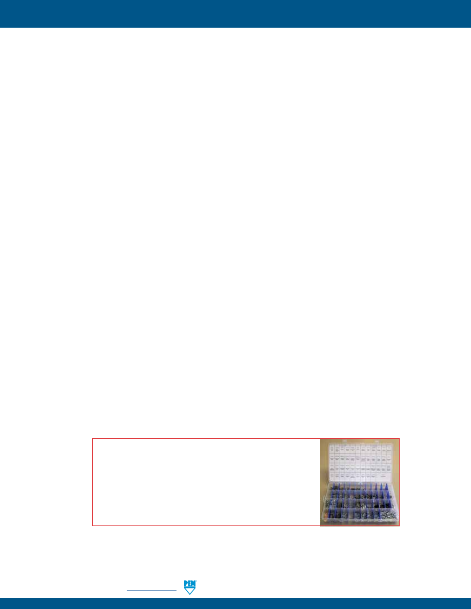
PEM® FASTENER PROTOTYPE KIT
The PEM prototype kit contains a wide variety of PEM fasteners for your prototype needs.
The kit contains over 1,000 different nuts, studs, standoffs, and panel fasteners of various
types and sizes, so you can choose the one which will best suit your specific design
requirements. The kit is available with unified or metric parts. Price U.S. $99.00 (subject to
change without notice).
INDEX-7
PennEngineering •
www.pemnet.com
pem-html.html
HOW CAN WE HELP?
PennEngineering offers a wide range of technical support assistance. Let us put our expertise to work for you. We can provide:
Training
▶
On customer site group or individual training by a technical representative and/or PEM® factory personnel
▶
Tutorial materials on website
Global Network of Engineering Representatives to:
▶
Provide local company liaison
▶
Provide application review/product selection
▶
Provide technical materials
▶
Provide on-site product training and new product updates
▶
Assist with quotations
▶
The representative nearest you can be found on our website.
rep/distributor locator
Application Engineering Services and Online Tools
▶
Application analysis/review
▶
Custom solutions
▶
Online technical papers
▶
Get answers to technical questions at
techsupport@pemnet.com
▶
Customer assist performance testing
▶
Cost Savings Investigation (CSI)
▶
Custom design and product development
▶
Customer drawings
▶
Finite Element Analysis (FEA)
▶
Free samples on standard (catalog) products
▶
3D Models (download or direct insert free on website)
▶
Free design PEMspec™ APP
▶
Instructional videos and animations
Technical Lab Services
- Complete testing in accordance with NASM 25027, 45938 and ASTM as well as PEM® fastener test specs and customer parameters.
▶
Mechanical testing
▶
Tensile strength
▶
Compression
▶
In sheet performance
▶
Micro hardness (Knoop, Rockwell and superficial)
▶
Thermal Cycling
▶
Image analysis
▶
Corrosion and plating issues and analysis
Prototype Development Center
- Shop equipped with latest CNC equipment to provide prototype or short run samples and necessary installation tooling.
Capabilities include:
▶
Turning
▶
Milling
▶
Drilling
▶
3D Printing
▶
Installation
▶
Reaming
▶
Punching
▶
Grinding
▶
Assembly
Installation Equipment
We can assess your application and recommend equipment that helps you achieve your lowest installed cost. PEMSERTER® systems can be developed to
handle multiple fastener types simultaneously or even in-die equipment to address challenging component handling and fastener installation. For more
information call us at 800-523-5321 (USA only) or 215-766-8853 or visit us at
www.pemnet.com
.
INDEX-8
All PEM® products meet our stringent quality standards. If you require additional industry or other specific
quality certifications
, special procedures and/or part
numbers are required. Please contact your local sales office or representative for further information.
Regulatory
compliance information
is available in Technical Support section of our website. Specifications subject to change without notice. See our website for the
most current version of this bulletin.
North America:
Danboro, Pennsylvania USA
•
E-mail:
info@pemnet.com
•
Tel: +1-215-766-8853
•
800-237-4736 (USA)
Europe:
Galway, Ireland
•
E-mail:
europe@pemnet.com
•
Tel: +353-91-751714
Asia/Pacific:
Singapore
•
E-mail:
singapore@pemnet.com
•
Tel: +65-6-745-0660
Shanghai, China
•
E-mail:
china@pemnet.com
•
Tel: +86-21-5868-3688
Visit our PEMNET™ Resource Center at
www.pemnet.com
•
Technical support e-mail:
techsupport@pemnet.com
Stay connected to PennEngineering
Now you can follow us for the latest news releases, new
products, bulletin updates, tech tips, videos and more.
pem-html.html
ALA
™
FLOATING
SELF-CLINCHING
FASTENERS
PEM® floating self-clinching fasteners
are available with or without locking
threads.
Bulletin ALA-1217
pem-html.html
ALA-2
PennEngineering •
www.pemnet.com
U
NIF
IE
D
NON-LOCKING
AS, AC, A4 Nuts
SELF-LOCKING
LAS, LAC, LA4 Nuts
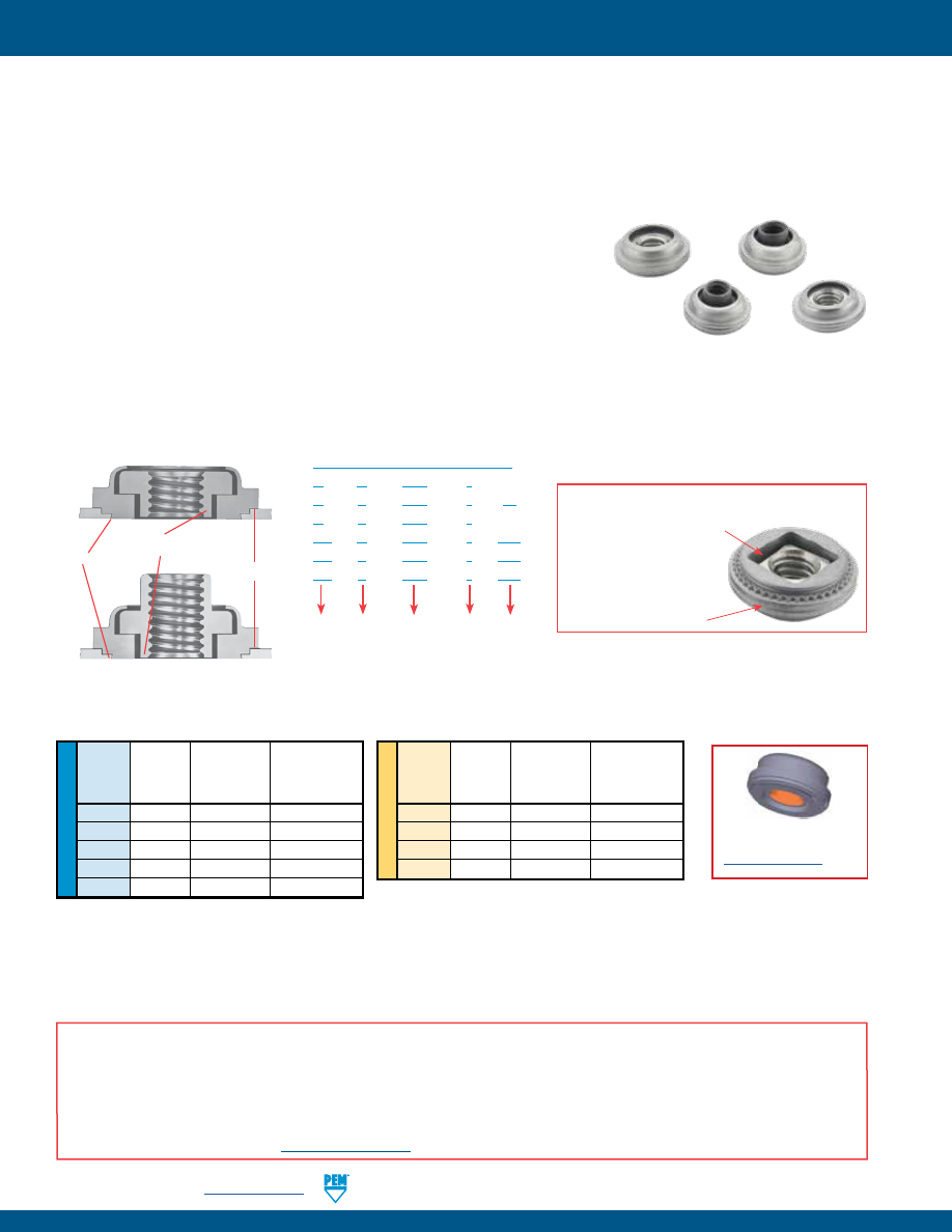
No Protrusion
Threads Extend into
Retainer Shank
Positive
Stop
Locking and Non-locking Threads
•
Provide load-bearing threads in thin sheets
•
Permit a total of .030”/0.76 mm adjustment for mating hole misalignment.
•
Sheet remains flush on one side, and the fastener is permanently locked in place.
•
Threads of the floating nut extend into the retainer shank for extra strength and support in assembly.
AC™/AS™/LAC™/LAS™ floating Nuts
•
Designed for clinching into steel or aluminum panels and sheets.
•
Available with (LAC/LAS) or without (AC/AS) locking threads.
A4™/LA4™ floating nuts
•
Provide prevailing torque locking threads with performance equivalent to applicable
NASM25027 specifications
(1)
.
•
Designed for clinching into stainless steel panels and sheets.
•
Available with (LA4) or without (A4) locking threads.
AC/AS
LAC/LAS
Type
A
C – 440 – 1
A
S – 440 – 1
ZI
A
4 – 440 – 1
LA
C – 440 – 1
MD
LA
S – 440 – 1
MD
LA
4 – 440 – 1
MD
Shank
Code
Thread
Size
Code
Finish
Code
Retainer
Material
Code
PART NUMBER DESIGNATION
PEM® Single groove
(Registered Trademark)
Identifies product for
installation into stainless
steel sheets (A4 and LA4)
PEM® Double Squares
(Registered Trademark)
(1) To meet national aerospace standards and to obtain testing documentation, product must be ordered to US NASM45938/11 specifications. Check
our web site for a complete Military Specification and National Aerospace Standards Reference Guide (Bulletin NASM). Screws for use with PEM
self-clinching locking fasteners should be Class 3A/4h fit or no smaller than Class 2A/6g.
Fastener drawings and
models are available at
www.pemnet.com
Locknut
Mating Screw
Mating Screw
Min. Axial
Strength Level
Tightening Torque
Thread
Strength (1)
(1)
(2)
Code
(lbs.)
(ksi)
(in. lbs.)
440
1085
180
15.8
632
1636
180
29.4
832
2522
180
53.8
032
3600
180
88.9
0420
5728
180
186
AXIAL STRENGTH AND TIGHTENING TORQUE - TYPES LAC/LAS/LA4
(1) All LAC, LAS and LA4 locknuts have axial strength exceeding the minimum tensile strength of 180 ksi/Property Class 12.9 screws. Contact techsupport
regarding assemble strength for higher strength screws.
(2) Tightening torque shown will induce preload of 65% of locknut minimum axial strength with K or nut factor is equal to 0.20. In some applications
tightening torque may need to be adjusted based on the actual K value. All tightening torques shown are based on 180 ksi/ Property Class 12.9 screws.
For lower strength screws the tightening torque is proportionately less. For example, for 120 ksi screws, torque is 67% value shown. For 900 MPa screws
(Property Class 9.8) torque value is 74% of value shown.
ME
TR
IC
Locknut
Mating Screw
Mating Screw
Min. Axial
Strength Level
Tightening Torque
Thread
Strength (1)
(1)
(2)
Code
(kN)
(MPa)
(N•m)
M3
6.14
1220
2.39
M4
10.71
1220
5.57
M5
17.3
1220
11.2
M6
24.55
1220
19.1
A NOTE ABOUT 400 SERIES FASTENERS FOR STAINLESS STEEL PANELS
In order for self-clinching fasteners to work properly, the fastener must be harder than the sheet into which it is being installed. In the case of stainless steel panels,
fasteners made from 300 Series Stainless Steel do not meet this hardness criteria. It is for this reason that 400 series fasteners are offered (Types A4 and LA4). How-
ever, while these 400 Series fasteners install and perform well in 300 Series stainless sheets they should not be used if the end product:
•
Will be exposed to any appreciable corrosive presence.
•
Requires non-magnetic fasteners.
•
Will be exposed to any temperatures above 300˚F (149˚C)
If any of the these are issues, please contact
techsupport@pemnet.com
for other options.
FLOATING SELF-CLINCHING FASTENERS
LA4
A4
pem-html.html
PennEngineering •
www.pemnet.com
ALA-3
D
C
Threaded Top
Elliptically
Formed
A
SELF-LOCKING
LAS/LAC/LA4
T
2
E
U
NIF
IE
D
Internal,
Internal, UNJ Class 3B
Hardened
Zinc
Passivated
Zinc
Passivated
ASME
per ASME B1.15 /
400
300
300
Plated,
and/or
Plated,
and/or
Black
B1.1, 2B/
MJ Class 4H6H per
Hardened Series
Series
Series
5µm,
tested per
5µm,
tested per
Dry-film
HRB 70/
HRB 88/
ASME
ASME B1.21M
Carbon Stainless Stainless Carbon Stainless
Colorless
ASTM
Colorless
ASTM
Lubricant
HB 125
HB 183
Type
B1.13M, 6H
(M6 thread 4H5H)
Steel
Steel
Steel
Steel
Steel
(3)
A380
(3)
A380
(4)
or Less
or Less
AS
•
• •
•
•
AC
•
• •
•
•
A4
•
•
•
• •
LAS
•
• •
•
•
•
LAC
•
•
•
• • •
LA4
•
•
•
• • •
Part number codes for finishes
ZI
None
MD
Type
Non-Locking
Self-Locking
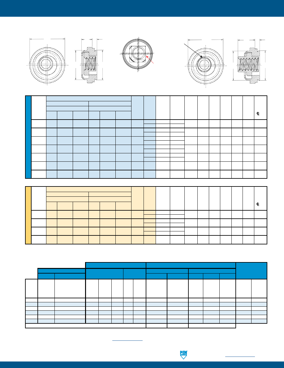
Hole
Min.
Thread
Thread Shank
A
Min.
Size in
C
D
E
T
1
T
2
Dist.
Size
Fastener Material
Fastener Material
Code Code (Shank) Sheet Sheet Max. Max. ±.015 Max. Max. Hole
300 Series 400 Series
300 Series 400 Series
Max.
Thickness
+.003
C/L
To
Steel Stainless Stainless Steel Stainless Stainless
–.000
Edge
.112-40
AS AC A4 LAS LAC LA4 440
1 .038 .038
.290 .289 .290 .360 .130 .190 .30
(#4-40)
2
(1)
.054 .054
.138-32
AS AC A4 LAS LAC LA4 632
1 .038 .038
.328 .327 .335 .390 .130 .200 .32
(#6-32)
2
(1)
.054 .054
.164-32
AS AC A4 LAS LAC LA4 832
1 .038 .038
.368 .367 .365 .440 .130 .210 .34
(#8-32)
2
(1)
.054 .054
.190-24
AS AC A4 LAS LAC LA4 024 1 .038 .038 .406 .405 .405 .470 .170 .270 .36
(#10-24)
2
(1)
.054 .054
.190-32
AS AC A4 LAS LAC LA4 032 1 .038 .038 .406 .405 .405 .470 .170 .270 .36
(#10-32)
2
(1)
.054 .054
.250-20
AS AC
– LAS LAC
– 0420 2 .054 .054 .515 .514 .510 .600 .210 .310 .42
(1/4-20)
.250-28
AS AC
– LAS LAC
– 0428 2 .054 .054 .515 .514 .510 .600 .210 .310 .42
(1/4-28)
Float –
.015”/0.38 mm minimum,
in all directions from center,
.030”/0.76 mm total.
Fastener Materials
Standard Finishes
For Use In
Threads
Non-locking
Self-locking
Sheet Hardness
Non-locking
Self-locking
Retainer
Nut
Retainer & Nut Retainer & Nut Retainer
Retainer
Nut
(2)
MATERIAL AND FINISH SPECIFICATIONS
NON-LOCKING
AS/AC/A4
E
D
C
A
T
1
(2) HRB - Hardness Rockwell “B” Scale. HB - Hardness Brinell.
(3) See PEM Technical Support section of our web site
(www.pemnet.com)
for related plating standards and specifications.
(4) Temperature limit 400˚ F / 204˚ C.
All dimensions are in inches.
All dimensions are in millimeters.
(1) This shank code is not available for A4 and LA4 nuts.
ME
TR
IC
Type
Non-Locking
Self-Locking
Hole
Min.
Thread
Thread Shank
A
Min.
Size in
C
D
E
T
1
T
2
Dist.
Size x
Fastener Material
Fastener Material
Code Code (Shank) Sheet Sheet Max. Max. ±0.38 Max. Max. Hole
Pitch
300 Series 400 Series
300 Series 400 Series
Max.
Thickness
+0.08
C/L
To
Steel Stainless Stainless Steel Stainless Stainless
Edge
M3 x 0.5
AS
AC A4 LAS LAC LA4 M3
1 0.97 0.97
7.37 7.35 7.37 9.14 3.31 4.83 7.62
2
(1)
1.38 1.38
M4 x 0.7
AS
AC A4 LAS LAC LA4 M4
1 0.97 0.97
9.35 9.33 9.28 11.18 3.31 5.34 8.64
2
(1)
1.38 1.38
M5 x 0.8
AS AC A4 LAS LAC LA4 M5
1 0.97 0.97
10.31 10.29 10.29 11.94 4.32 6.86 9.14
2
(1)
1.38 1.38
M6 x 1
AS
AC
–
LAS
LAC
–
M6
2
1.38
1.38
13.08
13.06
12.96
15.24
5.34
7.88
10.67
Clinching profile may vary.
Clinching profile may vary.
PEM® Double Squares are a
registered trademark.
FLOATING SELF-CLINCHING FASTENERS
pem-html.html
All PEM® products meet our stringent quality standards. If you require additional industry or other specific
quality certifications
, special procedures and/or part
numbers are required. Please contact your local sales office or representative for further information.
Regulatory
compliance information
is available in Technical Support section of our website. Specifications subject to change without notice. See our website for the
most current version of this bulletin.
North America:
Danboro, Pennsylvania USA
•
E-mail:
info@pemnet.com
•
Tel: +1-215-766-8853
•
800-237-4736 (USA)
Europe:
Galway, Ireland
•
E-mail:
europe@pemnet.com
•
Tel: +353-91-751714
Asia/Pacific:
Singapore
•
E-mail:
singapore@pemnet.com
•
Tel: +65-6-745-0660
Shanghai, China
•
E-mail:
china@pemnet.com
•
Tel: +86-21-5868-3688
Visit our PEMNET™ Resource Center at
www.pemnet.com
•
Technical support e-mail:
techsupport@pemnet.com
ME
TR
IC
U
NIF
IE
D
(1) Published installation forces are for general reference. Actual set-up and confirmation of complete installation should be made by observing proper
seating of fastener as described in the installation steps. Other performance values reported are averages when all proper installation parameters
and procedures are followed. Variations in mounting hole size, sheet material, and installation procedure may affect performance. Performance
testing this product in your application is recommended. We will be happy to provide technical assistance and/or samples for this purpose.
(2) For LAC, LAS and LA4 nuts, thread locking performance is equivalent to applicable NASM25027 specifications. Consult document PEM-REF25027 for details.
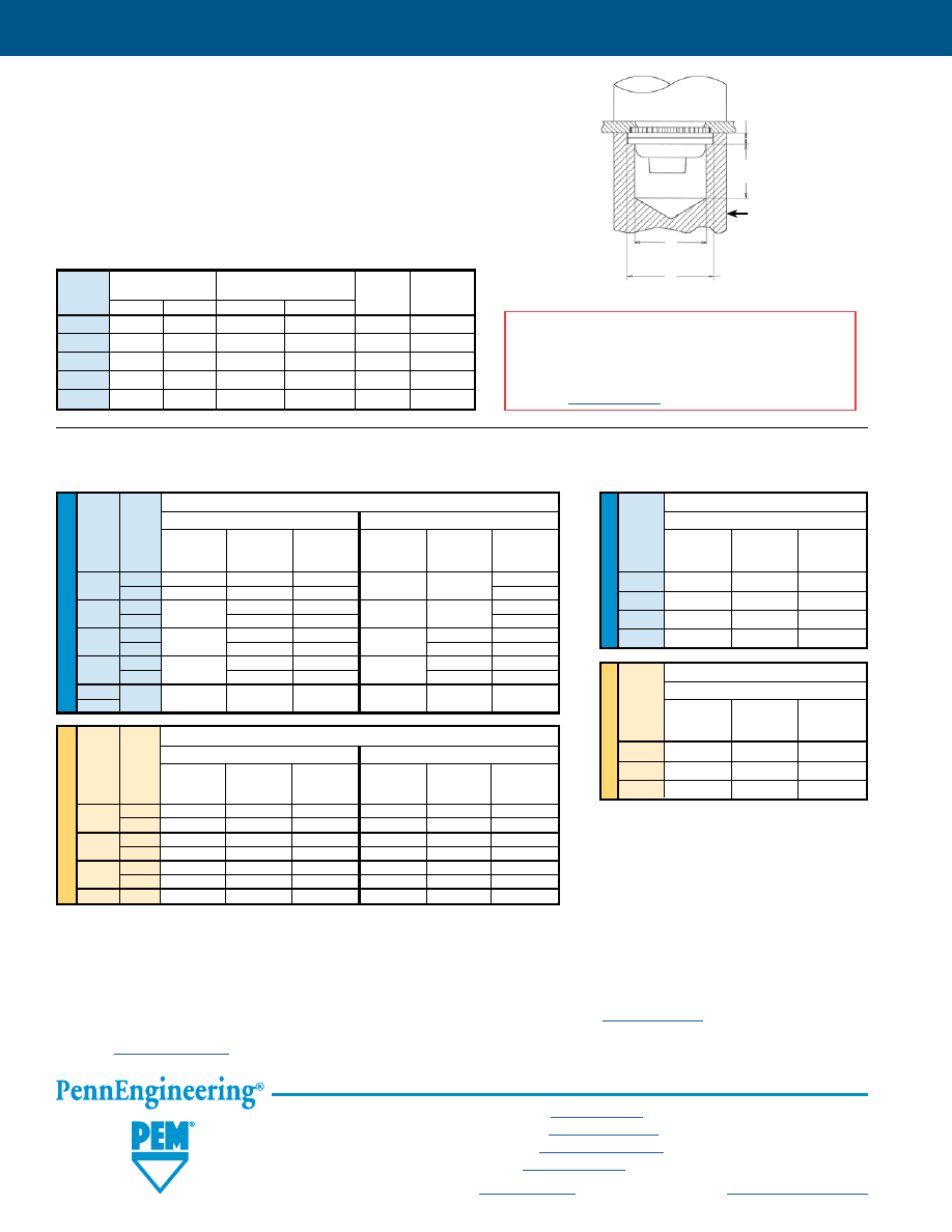
1.
Prepare properly sized mounting hole in sheet. Do not perform any secondary
operations such as deburring.
2.
Place fastener into the anvil hole and place the mounting hole (preferably the
punch side) over the shank of the fastener.
3.
With installation punch and anvil surfaces parallel, apply sufficient squeezing
force until anvil contacts the mounting sheet. Drawing shows suggested
tooling for applying these forces.
ALA-4
PERFORMANCE DATA
(1)(2)
AC/AS/LAC/LAS NUTS
ME
TR
IC
U
NIF
IE
D
Test Sheet Material
5052-H34 Aluminum
Cold-Rolled Steel
Thread Shank Retainer Retainer
Retainer Retainer
Code Code
Installation
Pushout Torque-out Installation
Pushout Torque-out
(lbs.)
(lbs.)
(in. lbs.)
(lbs.)
(lbs.)
(in. lbs.)
440 1 1500 215 65 3000 300 85
2
2000
225
80
150
632 1 2000 240 140 3000 300 150
2
250
150
175
832 1 2000 250 140 3000 300 150
2
265
150
400
200
032 1 2000 300 150 3500 400 150
2
350
175
450
200
0420
2 3000 400 325 5000 500 325
0428
Test Sheet Material
5052-H34 Aluminum
Cold-Rolled Steel
Thread Shank Retainer Retainer
Retainer Retainer
Code Code
Installation
Pushout Torque-out Installation
Pushout Torque-out
(kN)
(N) (N•m) (kN)
(N) (N•m)
M3
1 6.7 956 7.3 13.3 1334 9.6
2
8.9
1000
9
13.3
1334
16.9
M4
1 8.9 1112 15.8 13.3 1334 16.9
2 8.9 1178 16.9 13.3 1779 22.6
M5
1 8.9 1334 16.9 15.6 1779 16.9
2
8.9
1556
19.7
15.6
2001
22.6
M6
2
13.3
1779
36.7
22.2
2224
36.7
Test Sheet Material
300 Series Stainless Steel
Thread Retainer Retainer
Code
Installation
Pushout Torque-out
(lbs.)
(lbs.)
(in. lbs.)
440
9000
200
85
632
10000
200
85
832
12000
200
85
032
13000
250
125
Test Sheet Material
300 Series Stainless Steel
Thread Retainer Retainer
Code
Installation
Pushout Torque-out
(kN)
(N) (N•m)
M3
40
890
9.6
M4
53
890
9.6
M5
57
1100
14.1
A4/LA4
(3)
NUTS
INSTALLATION
PEMSERTER® Installation Tooling - AC/AS/LAC/LAS/A4/LA4 NUTS
PUNCH
D*
+.002 /+0.05 mm
+.005”/+0.13 mm
E*
+.004” –.000” / +0.1 mm
B
ANVIL
A
* For “D” and “E”,
see page 3.
Counterbore Hole Depth Below Counterbore
Thread A
B
Anvil Part
Punch
Code
±.001
±0.03
±.005
±0.13
Number
Part
440/M3
.054
1.37
.258
6.55
8013889 975200048
632
.054
1.37
.258
6.55
8013890 975200048
832/M4
.054
1.37
.258
6.55
8013891 975200048
032/M5
.071
1.8
.241
6.12
8013892 975200048
0420/M6
.092
2.34
.220
5.59
8021392
8012030
(3) Specifically designed for installation into
stainless steel.
FLOATING SELF-CLINCHING FASTENERS
INSTALLATION NOTES
•
For best results we recommend using a PEMSERTER® press for
installation of PEM self-clinching fasteners. Please check our
website for more information.
•
Visit the Animation Library on our website to view the installation
process
for select products
.
pem-html.html
SELF-CLINCHING BLIND FASTENERS
BULLETIN
B
916
pem-html.html
B-2
PennEngineering • www.pemnet.com
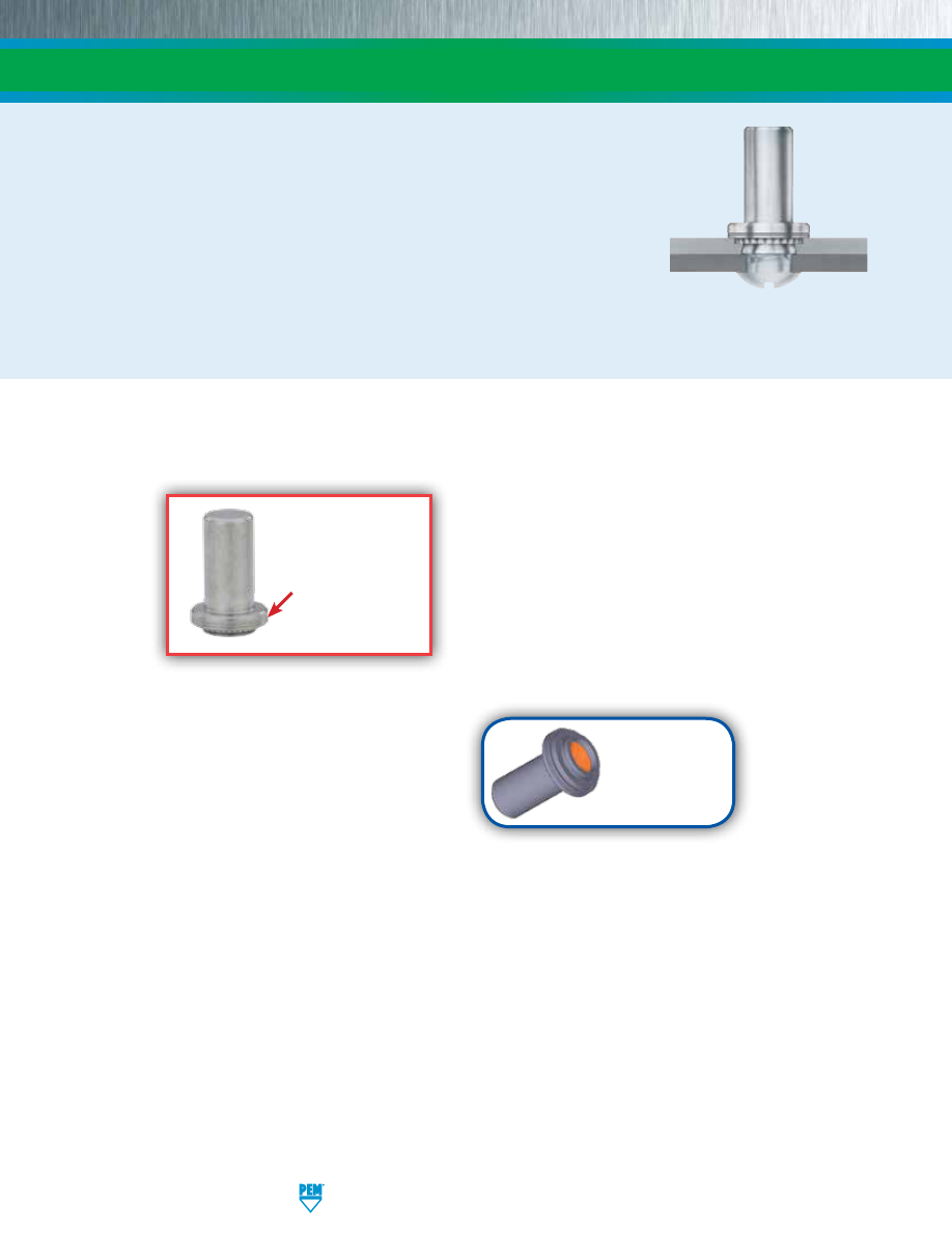
SELF-CLINCHING BLIND FASTENERS
PEM® brand self-clinching blind fasteners provide permanently mounted blind threads in
metal sheets as thin as .040” / 1 mm.
•
Provides barrier to protect threads against foreign matter.
•
Limits screw penetration, protecting internal components from potential damage.
PEM blind fasteners employ the proven PEM self-clinching design and are easily installed into
properly sized holes. Shanks of PEM fasteners act as their own pilots. PEM blind fasteners can be
installed with any standard press applying squeezing forces between parallel surfaces.
PEM self-clinching blind fasteners are available in thread sizes from #4-40 through 1/4-20 / M3 through M6 in carbon or stainless steel.
PEM®
“two groove”
(Registered Trademark)
Fastener drawings
and models are
available at
www.pemnet.com
pem-html.html
ME
TR
IC
Threads
Fastener Materials
Standard Finishes
For Use in Sheet Hardness: (2)
Internal,
Passivated and/or
HRB 80 /
HRB 70 /
ASME B1.1, 2B /
Hardened
300 Series
Tested Per
Zinc Plated, 5µm,
HB 150
HB 125
Type
ASME B1.13M, 6H
Carbon Steel
Stainless Steel
ASTM A380
Colorless (1)
or less
or less
B
• • • •
BS
• • •
•
Part Number Code For Finishes
None ZI
PennEngineering • www.pemnet.com
B-3
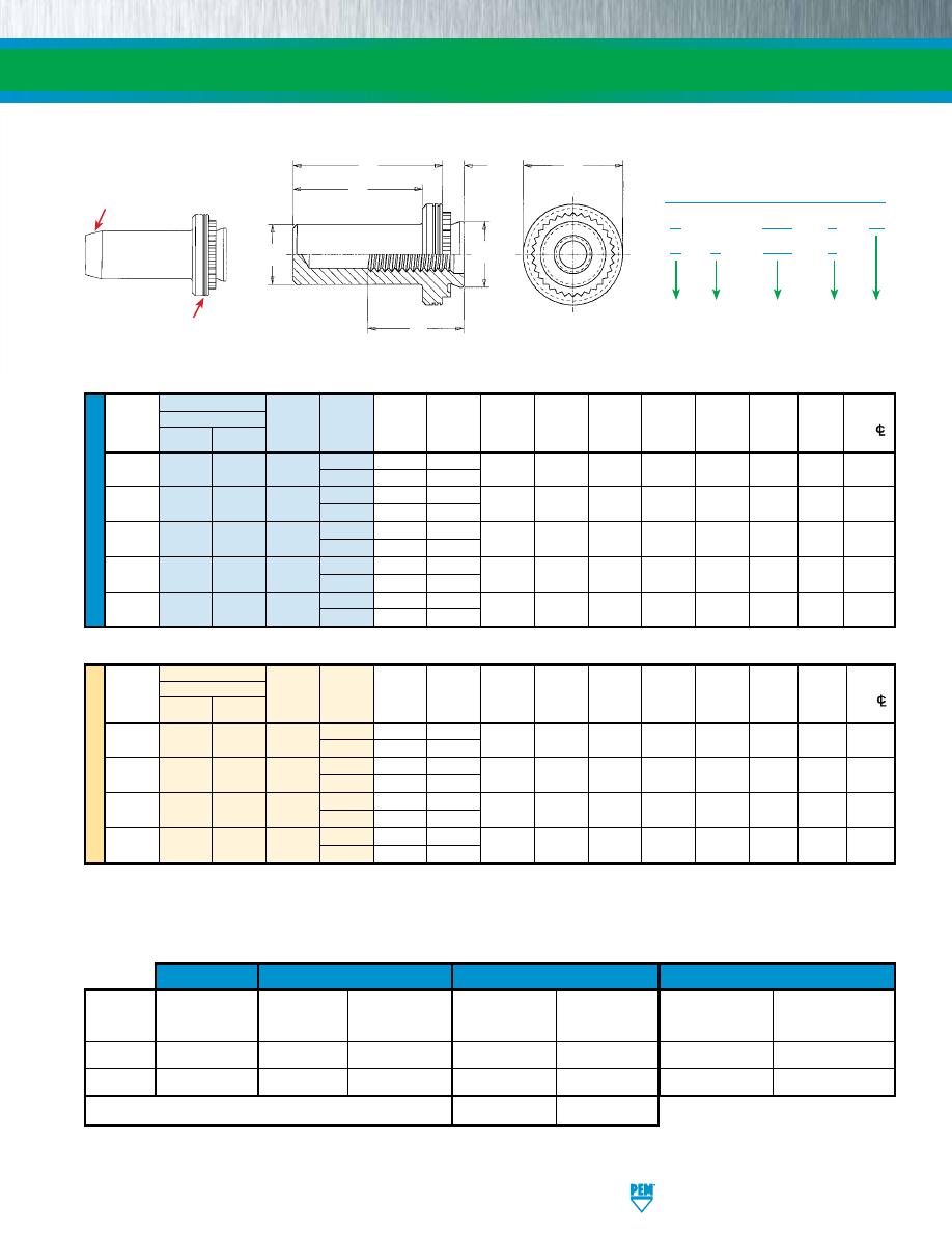
U
NIF
IE
D
Type
A
Min.
Hole Size
Thread
Fastener Material
Thread Shank (Shank)
Sheet
in Sheet
B
C
E
F
L
T
Min. Dist.
Size
Steel Stainless
Code Code Max. Thickness + .003
Max.
Max.
± .010
Min.
Max.
± .010
Hole
C/L
Steel
-
.000
to
Edge
.112-40
B BS 440
1 .038 .040
.166 .150 .165 .250 .210 .335 .380 .19
(#4-40)
2 .054 .056
.138-32
B BS 632
1 .038 .040
.1875 .169 .187 .280 .230 .335 .380 .22
(#6-32)
2 .054 .056
.164-32
B BS 832
1 .038 .040
.213 .204 .212 .310 .280 .385 .440 .27
(#8-32)
2 .054 .056
.190-32
B BS 032
1 .038 .040
.250 .235 .249 .340 .280 .385 .440 .28
(#10-32)
2 .054 .056
.250-20
B BS 0420
1 .054 .056
.344 .305 .343 .430 .310 .500 .560 .34
(1/4-20)
2 .087 .090
All dimensions are in inches.
Thread Type
A
Min.
Hole Size
Size x Fastener Material Thread Shank (Shank)
Sheet
in Sheet
B
C
E
F
L
T
Min. Dist.
Pitch
Steel
Stainless Code Code Max.
Thickness
+ 0.08
Max.
Max.
± 0.25
Min.
Max.
± 0.25
Hole
C/L
Steel
to
Edge
M3 x 0.5
B
BS
M3
1 0.97 1
4.22 3.84 4.2 6.35 5.3 8.5 9.6 4.8
2
1.38
1.4
M4 x 0.7
B
BS
M4
1 0.97 1
5.41 5.2 5.38 7.95 7.1 9.8 11.2 6.9
2
1.38
1.4
M5 x 0.8
B
BS
M5
1 0.97 1
6.35 6.02 6.33 8.75 7.1 9.8 11.2 7.1
2
1.38
1.4
M6 x 1
B
BS
M6
1 1.38 1.4
8.75 7.8 8.73 11.1 7.8 12.7 14.3 8.6
2
2.21
2.29
All dimensions are in millimeters.
Metric parts are
identified by large
chamfer at blind end.
PEM®
“two groove”
registered trademark.
(1) See PEM Technical Support section of our web site (www.pemnet.com) for related plating standards and specifications.
(2) HRB - Hardness Rockwell “B” Scale. HB - Hardness Brinell.
SELF-CLINCHING BLIND FASTENERS
MATERIAL AND FINISH SPECIFICATIONS
B
S – 832 – 2
Type
Finish
PART NUMBER DESIGNATION
Material
Code
Thread
Size Code
Shank
Code
B – 832 – 2
ZI
T
L
A
E
C
F
Full Thread Depth
B
Clinching profile may vary.
pem-html.html
U
NIF
IE
D
(1) Published installation forces are for general reference. Actual set-up and confirmation of complete installation should be made by observing
proper seating of fastener as described in the installation steps. Other performance values reported are averages when all proper
installation parameters and procedures are followed. Variations in mounting hole size, sheet material, and installation procedure may affect
performance. Performance testing this product in your application is recommended. We will be happy to provide technical assistance and/
or samples for this purpose.
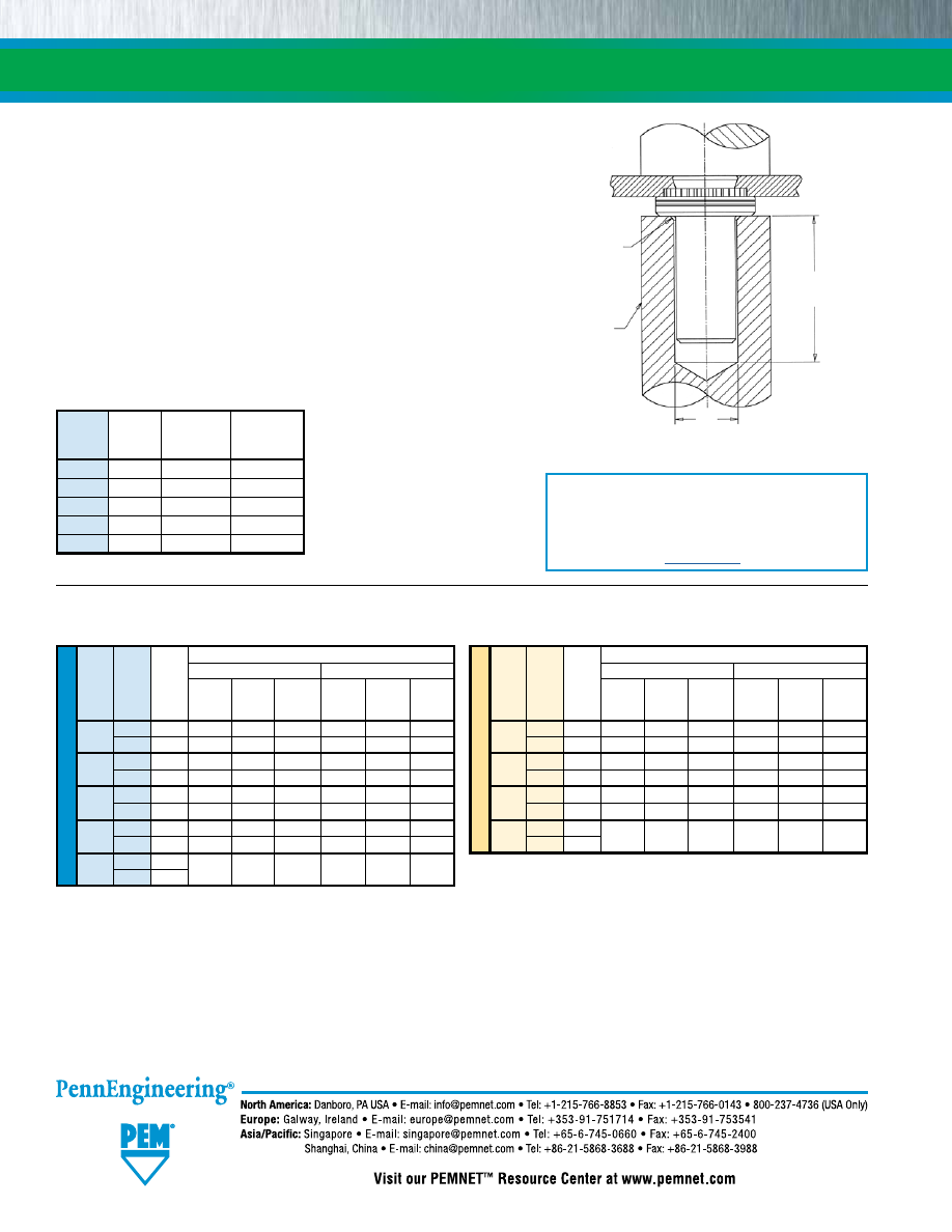
1.
Prepare properly sized mounting hole in the sheet. Do not perform
any secondary operations such as deburring.
2.
Place the barrel of the fastener into the anvil hole and place the
mounting hole (preferably the punch side) over the shank of the
fastener.
3.
With the installation punch and anvil surfaces parallel, apply
squeezing force until the flange contacts the mounting sheet. The
sketch at the right indicates suggested tooling for applying these
forces.
INSTALLATION NOTES
•
For best results we recommend using a PEMSERTER®
press for installation of PEM Types B and BS fasteners.
Please check our website for more information.
•
Visit the Animation Library on our website to view the
installation process
for this product
.
Test Sheet Material
Thread Shank Sheet
5052-H34 Aluminum
Cold-Rolled Steel
Code Code Thick- Install- Torque-
Install- Torque-
ness ation Pushout out ation Pushout out
(in.) (lbs.) (lbs.) (in.
lbs.) (lbs.) (lbs.) (in.
lbs.)
440
1 .040 1600 90 10 2500 125 13
2 .056 2000 170
13 3500 230
18
632
1 .040 1800 95 17 3000 130 18
2 .056 2800 190
22 4000 260
28
832
1 .040 2000 105 23 3500 135 30
2 .056 3000 220
35 5000 285
45
032
1 .040 2100 110 32 4000 140 35
2 .056 3500 190
50 5000 250
60
0420
1 .056
4000 315 90 6000 400 105
2 .090
B-4
SELF-CLINCHING BLIND FASTENERS
PERFORMANCE DATA
(1)
INSTALLATION
B
+ .006” / 0.15 mm
+ .003” / 0.08 mm
L*
+.06” / 1.5 mm
MIN.
.010” / 0.25 mm
x 45˚ Nom.
Chamfer on anvil
PUNCH
ANVIL
* For “L”,
see page 3.
ME
TR
IC
Test Sheet Material
Thread Shank Sheet
5052-H34 Aluminum
Cold-Rolled Steel
Code Code Thick- Install- Torque-
Install- Torque-
ness ation Pushout out ation Pushout out
(mm) (kN) (N) (N•m) (kN) (N) (N•m)
M3
1 1 7.1 400 1.15 11.1 550 1.5
2 1.4
9
750 1.47
14 1010 2.05
M4
1 1 8.9 470 2.6 15.6 600 3.4
2 1.4 12.5 970
4
20 1250 5.1
M5
1 1 9.3 480 3.6 17.8 620 4
2 1.4 14
845
5.7
25
1112
6.8
M6
1 1.4
17.8 1400 10.2 25.7 1760 11.9
2 2.3
Anvil
Punch
Type Thread
Part Part
Code
Number Number
B/BS 440/M3 975200001 975200048
B/BS
632 975200002 975200048
B/BS 832/M4 975200003 975200048
B/BS 032/M5 975200004 975200048
B/BS 0420/M6 975200005 975200048
PEMSERTER® Installation Tooling
Technical support e-mail: techsupport@pemnet.com
All PEM® products meet our stringent quality standards. If you require additional industry or other specific quality certifications, special procedures and/or part
numbers are required. Please contact your local sales office or representative for further information.
Regulatory compliance information is available in Technical Support section of our website. Specifications subject to change without notice. See our website for the
most current version of this bulletin.
© 2016 PennEngineering.
pem-html.html
CH
™
CONCEALED-HEAD
SELF-CLINCHING
STUDS AND STANDOFFS
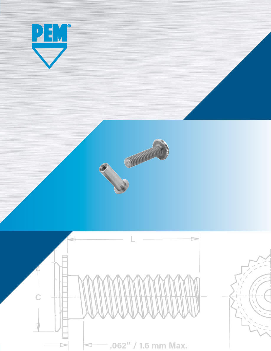
PEM® concealed-head self-clinching
studs and standoffs install permanently
and promote smooth designs.
Bulletin CH-1217
pem-html.html
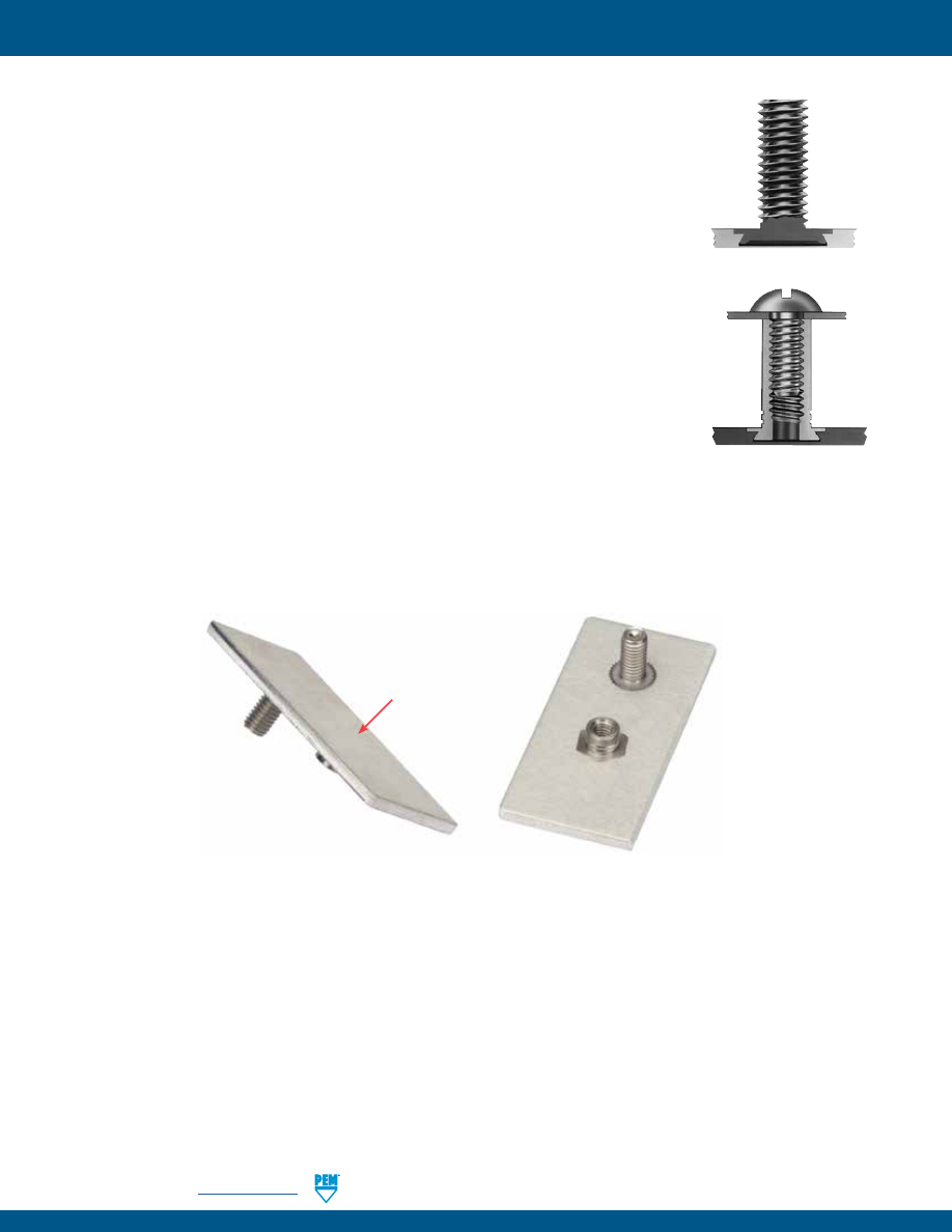
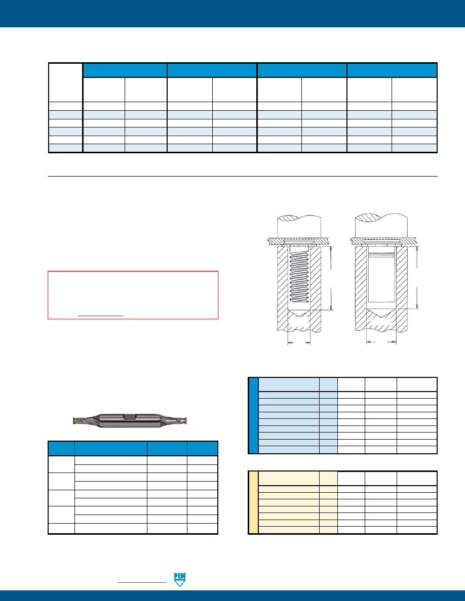
Concealed-head self-clinching studs and standoffs install permanently and
promote smooth designs:
•
Install permanently in steel or aluminum sheets as thin as .062” / 1.6 mm to provide strong
and reusable threads for mating hardware in a wide range of assembly applications.
•
Allow the side of the sheet opposite installation to remain smooth and unmarred.
•
One side installation additionally serves to satisfy strict ingress protection (IP)
requirements where the sheet must remain completely sealed from air, liquid, dust,
gases or other potentially infiltrating elements.
•
Only require a blind milled hole to the recommended size and minimum depth.
•
Install using a PEMSERTER® press or other standard press.
•
CFHC™ studs can be ordered to NAS63540/4 specifications.
(1)
Concealed-head Stud
Concealed-head Standoff
Back side of sheet
remains smooth
(1) To meet national aerospace standards and to obtain testing documentation, Type CFHC studs must be
ordered using appropriate NAS63540/4 part number. Check our web site for a complete Military Specification
and National Aerospace Standards Reference Guide (Bulletin NASM).
CONCEALED-HEAD SELF-CLINCHING STUDS AND STANDOFFS
CH-2
PennEngineering •
www.pemnet.com
pem-html.html
ME
TR
IC
U
NIF
IE
D
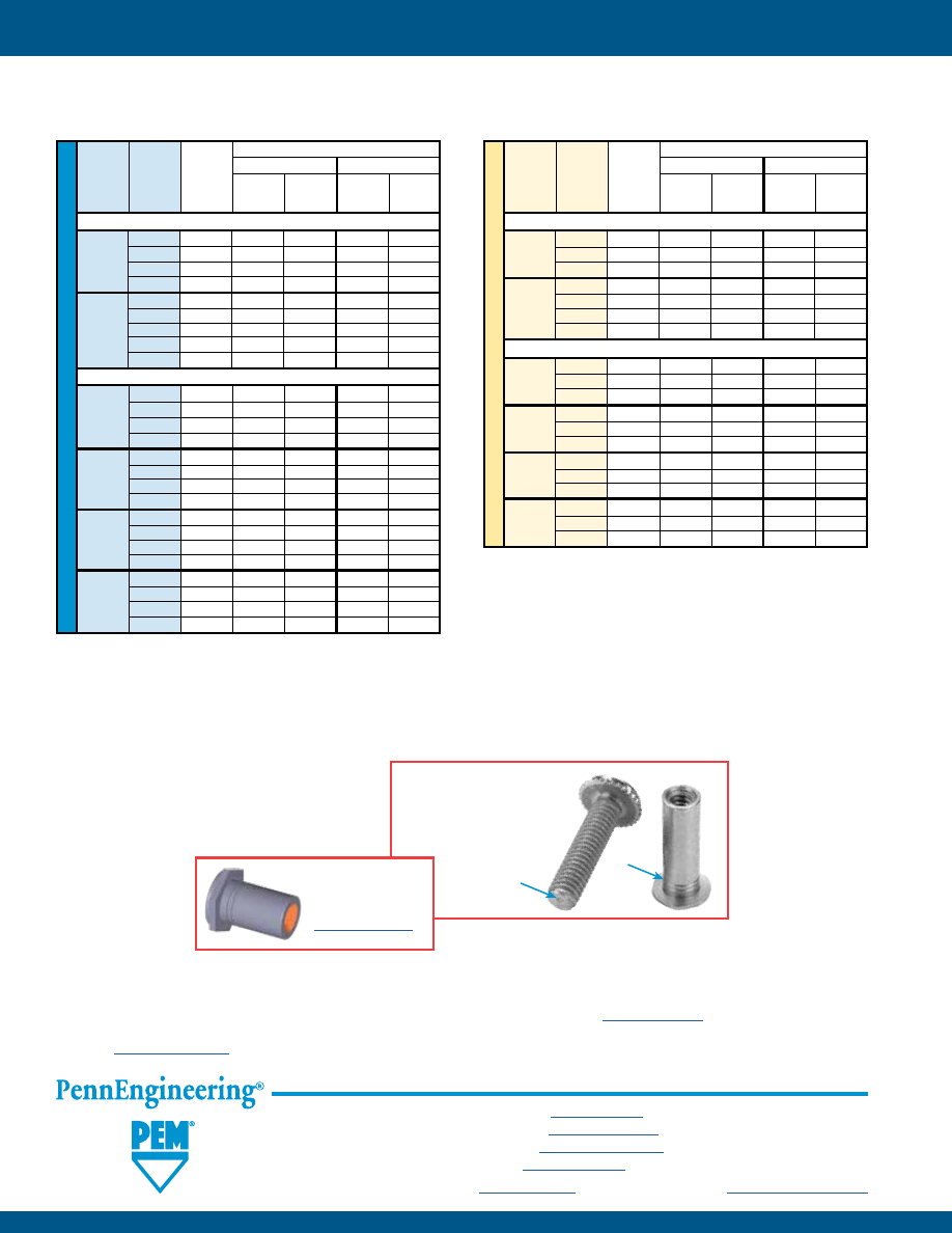
Type
Length Code “L” ±.015
Blind Min.
(Length code is in 16ths of an inch)
Min. Mounting Depth
Max.
Thread Thread
Sheet Hole Dia. of Blind
A
E
C
Min. Dist. Hole In
Size
Aluminum Stainless
Code
.250 .375 .500 .625 .750 1.00
Thick- +.003 Hole (Shank) ±.010
Max. Hole
CL
Attached
Steel
ness -.000 (1) Max. To Edge
Parts
.112-40 CHA CHC
440 4 6 8 10 12 —
.062
.172
.043 .041
.205 .171 .156 .135
(#4-40)
CFHA
CFHC
.093
.075
.071
.138-32 CHA CHC
632 4 6 8 10 12 16
.062
.213
.043 .041
.250 .212 .188 .160
(#6-32)
CFHA
CFHC
.093
.075
.071
.164-32 CHA
CHC
832 4 6 8 10 12 16
.062
.290
.043 .041
.328 .289 .219 .185
(#8-32)
CFHA
CFHC
.093
.075
.071
.190-32 CHA CHC
032 — 6 8 10 12 16
.062
.312
.043 .041
.350 .311 .250 .210
(#10-32)
CFHA
CFHC
.093
.075
.071
Type
Blind Min.
Thread
Length Code “L” ±0.4
Min.
Mounting Depth
Max.
Size
x Thread
(Length code is in millimeters)
Sheet
Hole Dia. of Blind
A
E
C
Min. Dist. Hole In
Pitch
Aluminum Stainless
Code
Thick-
+0.08 Hole
(Shank) ±0.25 Max. Hole
CL
Attached
Steel
ness (1) Max. To Edge Parts
M3 x 0.5
CHA CHC
M3 6 8 10 12 16 20 —
1.6
4.37
1.1 1.04
5.21 4.35 4 3.6
CFHA
CFHC 2.4 1.91
1.8
M4 x 0.7
CHA CHC
M4 6 8 10 12 16 20 25
1.6
7.37
1.1 1.04
8.33 7.35 5.6 4.6
CFHA
CFHC 2.4 1.91
1.8
M5 x 0.8
CHA CHC
M5 — — 10 12 16 20 25
1.6
7.93
1.1 1.04
8.89 7.9 6.4 5.6
CFHA
CFHC 2.4 1.91
1.8
(1) Blind holes may be deeper than minimums except where sheet material is at or near minimum thickness. Fasteners should always be installed so the
flange is flush with the surface of the sheet.
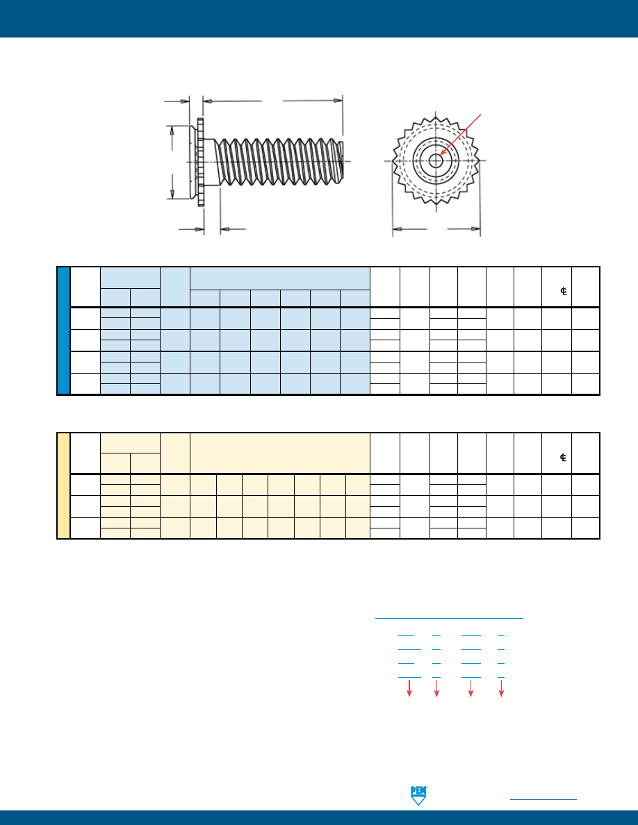
CHA™, CFHA™, CHC™ AND CFHC™ ALUMINUM AND STAINLESS STEEL STUDS
CH
A – 632 – 6
CFH A – 632 – 6
CH
C – 632 – 6
CFH C – 632 – 6
Type
PART NUMBER DESIGNATION
Material
Length
Code
Thread
Code
L
E
A
C
.062” / 1.6 mm Max.
Dimple (Registered
Trademark)
Clinching profile may vary.
All dimensions are in inches.
All dimensions are in millimeters.
CONCEALED-HEAD SELF-CLINCHING STUDS AND STANDOFFS
PennEngineering •
www.pemnet.com
CH-3
pem-html.html
ME
TR
IC
U
NIF
IE
D
Min.
Type Min.
Blind Depth Min.
Min.
Thread Thread Sheet
Mounting of Depth
A
B C H Dist.
Size Code Thick-
Hole Dia. Blind Full (Shank) Max. Max. Nom. Hole
C/L
Stainless ness
+.003 Hole Thread Max.
(5)
To Edge
Steel
.187 .250 .312 .375 .500 .625 .750 1.00
-.000 (4) F
.112-40 CSS
440 3
(1)
4
(2)
5
(2)
6
(2)
8
(3)
10
(3)
12
(3)
16
(3)
.062
.213
.043
.188
.041
.165 .212 .250 .188
(#4-40)
CSOS .093 .075 .072
.138-32 CSS
632 3
(1)
4
(1)
5
(2)
6
(2)
8
(3)
10
(3)
12
(3)
16
(3)
.062
.290
.043
.250
.041
.213 .289 .312 .219
(#6-32)
CSOS .093 .075 .072
.164-32 CSS
832 3
(1)
4
(1)
5
(2)
6
(2)
8
(3)
10
(3)
12
(3)
16
(3)
.062
.312
.043
.250
.041
.245 .311 .344 .250
(#8-32)
CSOS .093 .075 .072
.190-32 CSS
032 3
(1)
4
(1)
5
(1)
6
(1)
8
(2)
10
(3)
12
(3)
16
(3)
.062
.344
.043
.375
.041
.290 .343 .375 .281
(#10-32)
CSOS .093 .075 .072
.250-20 CSS
0420 3
(1)
4
(1)
5
(1)
6
(1)
8
(2)
10
(2)
12
(3)
16
(3)
.062
.390
.043
.375
.041
.354 .389 .438 .375
(1/4-20)
CSOS .093 .075 .072
Min.
Type Min. Blind Depth Min.
Min.
Thread Thread Sheet
Mounting of Depth
A
B C H Dist.
Size x Code Thick- Hole Blind Full (Shank) Max. Max. Nom. Hole
C/L
Pitch Stainless ness
Diameter Hole Thread Max.
(5)
To Edge
Steel
+0.08 (4) F
M3 x 0.5
CSS
M3 4
(1)
6
(1)
8
(2)
10
(3)
12
(3)
16
(3)
20
(3)
25
(3)
1.6
5.41
1.1
5
1.04
4.2 5.39 6.35 4.8
CSOS
8
(3)
2.4 1.91 1.83
M4 x 0.7
CSS
M4 4
(1)
6
(1)
8
(2)
10
(2)
12
(3)
16
(3)
20
(3)
25
(3)
1.6
7.92
1.1
6.5
1.04
6.23 7.9 8.74 6.4
CSOS 10
(3)
2.4 1.91 1.83
M5 x 0.8
CSS
M5 4
(1)
6
(1)
8
(1)
10
(2)
12
(2)
16
(3)
20
(3)
25
(3)
1.6
8.74
1.1
9.6
1.04
7.37 8.72 9.53 7.2
CSOS 2.4 1.91 1.83
M6 x 1
CSOS
M6 4
(1)
6
(1)
8
(1)
10
(2)
12
(2)
16
(3)
20
(3)
25
(3)
2.4 9.9 1.91 9.6 1.83 9 9.89 11.11 9.5
(1)
Style #1. Minimum thread length is equal to barrel length “L”. Screw might not pass
through shank end. Screws with lengths exceeding “L” should not be used or they may
cause “jacking-out” of standoff from the sheet.
(2)
Style #2. Screw might not pass through unthreaded end. Screws with lengths
exceeding “L” should not be used or they may cause “jacking-out” of standoff from the
sheet.
(3)
Style #3. Blind.
(4) Blind mounting holes may be deeper than minimums except where sheet material is at or
near minimum thickness. Fasteners should always be installed so the flange is flush with
the surface of the sheet.
(5) If standoff is used as a bushing, the hole in attached part must not exceed “B” plus .020”
/ 0.51 mm.
Length Code “L” +.002 –.005
(Length code is in 16ths of an inch)
Length Code “L” +0.05 –0.13
(Length code is in millimeters)
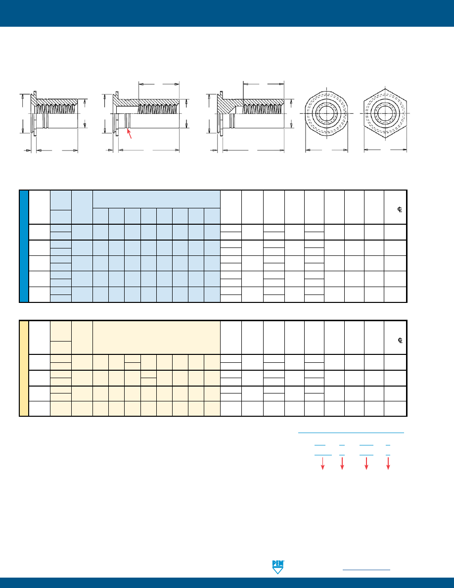
CSS™ AND CSOS™ STAINLESS STEEL STANDOFFS
CS
S – 632 – 6
CSO S – 632 – 6
Type
PART NUMBER DESIGNATION
Material
Length
Code
Thread
Code
L
H
TYPE CSS
TYPE CSOS
H
C
F
B
A
Style #2
Style #3
C
F
B
L
A
Style #1
C
B
L
A
Two Groove
(Registered Trademark)
Clinching profile may vary.
All dimensions are in inches.
All dimensions are in millimeters.
CONCEALED-HEAD SELF-CLINCHING STUDS AND STANDOFFS
PennEngineering •
www.pemnet.com
CH-4
pem-html.html
Threads
Fastener Materials
Finish
For Use In Sheet Hardness (1)
Passivated
Type
External, Internal,
300
Series
and/or
HRB 70 /
HRB 50 /
ASME B1.1 2A / ASME B1.1 2B /
Aluminum
Stainless Steel
No Finish
tested per
HB 125
HB 89
ASME B1.13M, 6g ASME B1.13M, 6H
ASTM
A380 or Less
or Less
CHA
•
•
•
•
CFHA
•
•
•
•
CHC
•
•
•
•
CFHC
•
•
•
•
CSS
•
•
•
•
CSOS
•
•
•
•
1.
Mill a round blind hole to the correct minimum depth.*
2.
Place fastener into anvil hole.
3.
Place the mounting hole over the shank of the fastener.
4.
With punch and anvil surfaces parallel, apply squeezing
force until the flange is flush with the mounting sheet.
* End mills available from PennEngineering. See chart below.
CFHA, CFHC, CHC, CHA
Concealed-head studs
CSOS, CSS
Concealed-head standoffs
D
D
PUNCH
PUNCH
ANVIL
ANVIL
L + .250”/
6.35 mm
L + .250”/
6.35 mm
All dimensions are in inches.
Thread
Fastener Type
Required Size
PEM
Code
End Mill
Part No.
440, M3
CFHC, CHC, CFHA, CHA Studs
.172”
CHM-172
CSOS, CSS Standoffs
.213”
CHM-213
632
CFHC, CHC, CFHA, CHA Studs
.213”
CHM-213
CSOS, CSS Standoffs
.290”
CHM-290
832, M4
CFHC, CHC, CFHA, CHA Studs
.290”
CHM-290
CSOS, CSS Standoffs
.312”
CHM-312
032, M5
CFHC, CHC, CFHA, CHA Studs
.312”
CHM-312
CSOS, CSS Standoffs
.344”
CHM-344
0420, M6
CSOS Standoffs
.390”
CHM-390
All dimensions are in millimeters.
END MILL INFORMATION
Double-ended, two-flute H.S.S. center-cutting end mills
are available from stock.
PennEngineering does not manufacture center-cutting
end mills, but we do keep a supply in stock for your
convenience.
(1) HRB - Hardness Rockwell “B” Scale. HB - Hardness Brinell.
PEMSERTER® Installation Tooling
MATERIAL AND FINISH SPECIFICATIONS
INSTALLATION
U
NIF
IE
D
Type
Thread
D
Punch Anvil
Code +.003 –.000 Part Number
Part Number
CHA / CHC / CFHA / CFHC
440
.127
975200048
970200006300
CHA / CHC / CFHA / CFHC
632
.139
975200048
970200007300
CHA / CHC / CFHA / CFHC
832
.179
975200048
970200008300
CHA / CHC / CFHA / CFHC
032
.205
975200048
970200009300
CSS / CSOS
440
.170
975200048
970200014300
CSS / CSOS
632
.218
975200048
970200015300
CSS / CSOS
832
.250
975200048
970200016300
CSS / CSOS
032
.295
975200048
970200017300
CSS / CSOS
0420
.358
975200048
970200018300
ME
TR
IC
Type
Thread
D
Punch Anvil
Code
+0.08
Part Number
Part Number
CHA / CHC / CFHA / CFHC
M3
3.4
975200048
970200229300
CHA / CHC / CFHA / CFHC
M4
4.4
975200048
970200019300
CHA / CHC / CFHA / CFHC
M5
5.4
975200048
970200020300
CSS / CSOS
M3
4.33
975200048
970200014300
CSS / CSOS
M4
6.36
975200048
970200016300
CSS / CSOS
M5
7.5
975200048
970200017300
CSS / CSOS
M6
9.13
975200048
970200018300
CONCEALED-HEAD SELF-CLINCHING STUDS AND STANDOFFS
CH-5
PennEngineering •
www.pemnet.com
INSTALLATION NOTES
•
For best results we recommend using a PEMSERTER® press for
installation of PEM self-clinching fasteners. Please check our
website for more information.
•
Visit the Animation Library on our website to view the installation
process
for select products
.
pem-html.html
ME
TR
IC
U
NIF
IE
D
Test Sheet Material
Max.
Cold-rolled Steel
5052-H34 Aluminum
Thread Tightening
Type Code
Torque
Ref.
Installation Pullout Installation Pullout
(in. lbs.)
(lbs.) (lbs.) (lbs.) (lbs.)
Concealed-head Standoffs
440 4.75 4,000 300 2,800 200
632 8.75 4,500 350 3,000 240
CSS
832 18 4,800 400 4,000 270
032 32 5,500 450 5,000 290
440 4.75 4,300 330 2,900 220
632 8.75 5,000 360 3,200 240
CSOS 832 18 5,300 440 4,000 300
032 32 6,000 600 5,000 400
0420 64 6,500 650 5,500 430
Concealed-head Studs
440 4.75 1,800 240 1,400 130
632 8.75 2,500 260 1,800 160
CHC
832 18 4,000 270 2,800 180
032 32 5,000 290 4,000 210
440 4.75 2,000 240 1,500 200
632 8.75 2,700 350 2,500 260
CFHC
832 18 3,300 440 3,000 310
032 32 4,000 680 3,500 360
440 2.85 (2) (2) 1,400 125
632 5.4 (2) (2) 1,800 135
CHA
832 10.8 (2) (2) 2,800 145
032 19.2 (2) (2) 4,000 170
440 2.85 (2) (2) 1,500 190
632 5.4 (2) (2) 2,500 220
CFHA
832 10.8 (2) (2) 3,000 240
032 19.2 (2) (2) 3,500 300
Test Sheet Material
Max.
Cold-rolled steel
5052-H34 Aluminum
Thread Tightening
Type Code
Torque
Ref.
Installation Pullout Installation Pullout
(N•m)
(kN) (N) (kN) (N)
Concealed-head Standoffs
M3 0.55 17.8 1330 12.5 890
CSS M4 2 21.3 1775 17.8 1200
M5 3.6 24.5 2000 22.2 1290
M3 .55 19.2 1465 12.9 975
CSOS
M4 2 23.6 1955 17.8 1335
M5 3.6 26.7 2665 22.2 1775
M6 7.2 28.9 2860 24.4 1915
Concealed-head Studs
M3 0.55 8 1065 6.2 575
CHC M4 2 17.8 1200 12.5 800
M5 3.6 22.2 1290 17.8 930
M3 0.55 8.9 1065 6.7 890
CFHC M4 2 14.7 1955 13.3 1375
M5 3.6 17.8 3020 15.6 1600
M3 0.3 (2) (2) 6.2 555
CHA M4 1.2 (2) (2) 12.5 645
M5 2.16 (2) (2) 17.8 755
M3 0.3 (2) (2) 6.7 845
CFHA M4 1.2 (2) (2) 13.3 1065
M5 2.16 (2) (2) 15.6 1330
(1) Published installation forces are for general reference. Actual set-up and confirmation of complete installation should be made by observing
proper seating of fastener as described in the installation steps. Other performance values reported are averages when all proper
installation parameters and procedures are followed. Variations in mounting hole size, sheet material, and installation procedure may affect
performance. Performance testing this product in your application is recommended. We will be happy to provide technical assistance and/
or samples for this purpose.
(2) Not recommended.
PERFORMANCE DATA
(1)
Look for the PEM® dimple
trademark on studs and
the PEM® “two groove”
trademark on standoffs.
CONCEALED-HEAD SELF-CLINCHING STUDS AND STANDOFFS
All PEM® products meet our stringent quality standards. If you require additional industry or other specific
quality certifications
, special procedures and/or part
numbers are required. Please contact your local sales office or representative for further information.
Regulatory
compliance information
is available in Technical Support section of our website. Specifications subject to change without notice. See our website for the
most current version of this bulletin.
North America:
Danboro, Pennsylvania USA
•
E-mail:
info@pemnet.com
•
Tel: +1-215-766-8853
•
800-237-4736 (USA)
Europe:
Galway, Ireland
•
E-mail:
europe@pemnet.com
•
Tel: +353-91-751714
Asia/Pacific:
Singapore
•
E-mail:
singapore@pemnet.com
•
Tel: +65-6-745-0660
Shanghai, China
•
E-mail:
china@pemnet.com
•
Tel: +86-21-5868-3688
Visit our PEMNET™ Resource Center at
www.pemnet.com
•
Technical support e-mail:
techsupport@pemnet.com
CH-6
Fastener drawings
and models
are available at
www.pemnet.com
pem-html.html
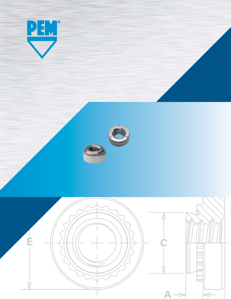
CL
™
SELF-CLINCHING
NUTS
PEM® brand self-clinching nuts install
permanently in aluminum, steel or
stainless steel sheets.
Bulletin CL-1016
Rev. 118
pem-html.html
CL-2
PennEngineering •
www.pemnet.com
SELF-CLINCHING NUTS
Many PEM self-clinching nuts in this bulletin are dimensionally equivalent to nuts manufactured to NASM45938/1 specifications. Consult our Marketing
department for a complete Military Specifications and National Aerospace Standards guide (Bulletin NASM) on our website.
Screws for use with PEM self-clinching locking fasteners should be Class 3A/4h fit or no smaller than Class 2A/6g.
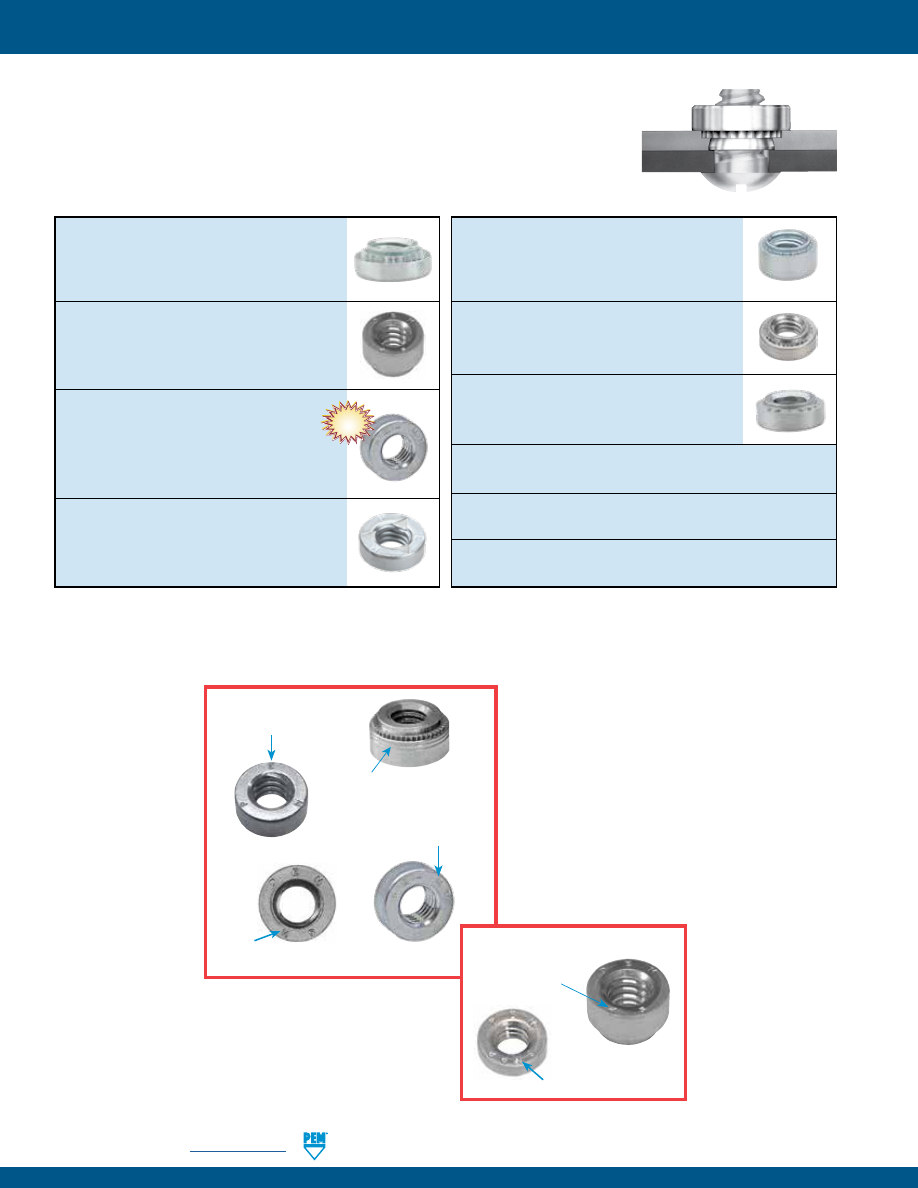
S™/SS™/CLA™/CLS™/CLSS™ nuts
provide load-bearing threads in thin
sheets with high pushout and torque-out
resistance
-
PAGES 4 and 5
SP™, PEM 300® nuts
provide strong
load-bearing threads in stainless steel
sheets as thin as .030”/0.8 mm
-
PAGES 4 and 5
S-RT™ free-running locknuts
are free-
running until clamp load is induced. A
modified thread angle on the loaded flank
provides the vibration resistant locking
feature
-
PAGE 6
SL™ self-locking nuts
are designed with
a unique and economical TRI-DENT®
locking feature, meeting 3 cycle locking
performance requirements
-
PAGE 7
Self-clinching nuts are installed by placing them in properly sized holes in sheets and
applying a parallel squeezing force to the head of the nut. The sheet metal surrounding the
head cold flows into an undercut thereby making the fastener an integral part of the sheet.
A serrated clinching ring prevents the fastener from rotating after installation.
H™ (non-locking) and HNL™ (locking)
nuts
have threads that provide high
pushout and torque-out resistance
-
PAGE 8
SH™ hard panel nuts
install into thin,
harder, high strength steel materials -
PAGE 8
SMPS™/SMPP™ nuts
are for thinner
sheet/close-to-edge applications
-
PAGE 9
Material and finish specifications -
PAGE 9
Installation -
PAGES 10 and 11
Performance data -
PAGES 12 - 15
© 2017 PennEngineering.
PEM® Two Groove
(Registered Trademark)
PEM® Stamp
(Registered Trademark)
SH
(Registered Trademark)
“PEM RT” Stamp
(Trademark)
NEW!
SP
Identification
Mark
Fasteners For Stainless Steel
SMPP
Identification Mark
pem-html.html
PennEngineering •
www.pemnet.com
CL-3
SELF-CLINCHING NUTS
Recommended
Thinnest Locking Threads Closest Superior Recommended Compatible Harder
panel
sheet
centerline-to-
corrosion
for installation
with aluminum
high strength
material
(1)
.025” /
Free- Prevailing edge distance
resistance
into stainless
anodizing
steel material Non-magnetic
0.64 mm
running
torque
steel sheets
A p p l i c a t i o n R e q u i r e s :
PEM
Nut
Type
S/SS/H
steel / aluminum
CLS/CLSS
steel / aluminum
• •
CLA
aluminum
• • •
SP
stainless steel
• • •
S-RT
steel / aluminum
•
SL
steel / aluminum
•
HNL
aluminum
•
SH
hardened alloy steel
•
SMPS
steel / aluminum
• •
•
•
SMPP
stainless steel
• •
•
•
•
PEM® SELF-CLINCHING NUT SELECTOR GUIDE
Thread Mask
PEM® Blu-Coat™ thread mask is available for applications where hardware is installed
prior to painting. During assembly, the threads of the mating hardware will remove
paint, electro deposited automotive under coatings, and weld spatter upon application
of torque. PEM nuts can be specially ordered with thread mask applied.
“BC” suffix will be added to part number to designate Blu-Coat thread mask to fastener.
Fastener drawings
and models are
available at
www.pemnet.com
(1) Describes “best practice” for typical applications. Fasteners can be used in other panel materials not listed here if specified hardness limits are met. In
all cases “For Use in Sheet Hardness” information is shown in chart on page 9.
pem-html.html
CL-4
PennEngineering •
www.pemnet.com
SELF-CLINCHING NUTS
U
NIF
IE
D
Type
Min. Dist.
Thread Fastener Material
Thread
Shank
A
Rec.
Hole Size C E T Hole
CL
Size
Carbon
Stainless Hardened
Code
Code
(Shank)
Min. Sheet
In Sheet
Max.
±.010
±.010
To Edge
Steel
Steel
Stainless Steel
Max.
Thickness (1)
+.003 –.000
.086-56
0 .030 .030
(#2-56) S CLS SP
256 1
.038 .040 .166 .165 .250 .070 .19
2
.054
.056
.099-48
0 .030 .030
(#3-48) S CLS —
348 1
.038 .040 .166 .165 .250 .070 .19
2
.054
.056
0
.030
.030
.112-40
S CLS SP
440 1 .038 .040 .166 .165 .250 .070 .19
(#4-40)
2
.054
.056
3
(2)
.087 .090
0
.030
.030
.138-32
S CLS SP
632 1 .038 .040 .1875 .187 .280 .070 .22
(#6-32)
2
.054
.056
3
(2)
.087 .090
0
.030
.030
.164-32
S CLS SP
832 1 .038 .040 .213 .212 .310 .090 .27
(#8-32)
2
.054
.056
3
(2)
.087 .090
0
.030
.030
.190-24
SS CLSS
SP
024 1 .038 .040 .250 .249 .340 .090 .28
(#10-24)
2
.054
.056
3
(2)
.087 .090
0
.030
.030
.190-32
SS CLSS
SP
032 1 .038 .040 .250 .249 .340 .090 .28
(#10-32)
2
.054
.056
3
(2)
.087 .090
.216-24
1 .038 .040
(#12-24) S CLS —
1224 2 .054 .056 .277 .276 .370 .130 .31
3
.087
.090
0
.045
.047
.250-20
S
(3)
CLS
SP
0420 1 .054 .056 .344 .343 .440 .170 .34
(1/4-20)
2
.087
.090
3
(2)
.120 .125
.250-28
1 .054 .056
(1/4-28) S CLS —
0428 2 .087 .090 .344 .343 .440 .170 .34
3 .120
.125
.313-18
1 .054 .056
(5/16-18) S
(3)
CLS
SP
0518
2
.087 .090 .413 .412 .500 .230 .38
3
(2)
.120 .125
.313-24
1 .054 .056
(5/16-24) S CLS SP 0524 2 .087 .090 .413 .412 .500 .230 .38
3
(2)
.120 .125
.375-16
1 .087 .090
(3/8-16) S CLS SP
0616 2 .120 .125 .500 .499 .560 .270 .44
3
(2)
.235 .250
.375-24
1 .087 .090
(3/8-24) S CLS SP
0624 2 .120 .125 .500 .499 .560 .270 .44
3
(2)
.235 .250
.438-20
S — — 0720 1 .087 .092 .562 .561 .687 .311 .562
(7/16-20)
.500-13
S CLS —
0813 1 .120 .125
(1/2-13)
2 .235 .250 .656 .655 .810 .360 .63
.500-20
S CLS —
0820 1 .120 .125
(1/2-20)
2 .235 .250
(Clinching profile may vary)
Due to manufacturing procedure, parts
may have a counterbore at shank end.
(1) For maximum performance, we recommend that you use the maximum shank length for your sheet thickness.
(2) This shank code not available for SP nuts.
(3) This thread size S nut, with a -2 shank code, can be installed successfully without the need to pre punch a mounting hole in a separate operation. See
page 15 for more information.
All dimensions are in inches.
•
S/SS nuts are recommended for use in steel
or aluminum sheets HRB 80 / HB 150 or
less.
•
CLS/CLSS nuts are recommended for use
in steel or aluminum sheets HRB 70 / HB
125 or less.
•
SP nuts are recommended for use in
stainless steel sheets HRB 90 / HB 192 or
less.
•
CLA nuts are recommended for use in steel
or aluminum sheets HRB 50 / HB 82 or less.
S™/SS™/CLS™/CLSS™/SP™ NUTS
The increased hardness of stainless steel panels requires careful consideration when installing self-
clinching fasteners. See page 16 or refer to Fastener Installation Dos and Don’ts on our web site.
C
E
A
T
Type
S – 632 – 1
ZI
SS – 032 – 1
ZI
CL S – 632 – 1
CLS S – 032 – 1
S P – 632 – 1
CL A – 632 – 1
Shank
Code
Thread
Size
Code
Finish
Material
Code
PART NUMBER DESIGNATION
pem-html.html
PennEngineering •
www.pemnet.com
CL-5
SELF-CLINCHING NUTS
(1) For maximum performance, we recommend that you use the maximum shank length for your sheet thickness.
(2) This shank code not available for SP nuts.
(3) This thread size S nut, with a -2 shank code, can be installed successfully without the need to pre punch a mounting hole in a separate operation. See
page 15 for more information.
ME
TR
IC
U
NIF
IE
D
(See drawing at top of page 4) All dimensions are in millimeters.
Type
Thread
Fastener Material
A
Min. Sheet
Hole Size
Min. Dist.
Size x
Thread
Shank
(Shank)
Thickness
In Sheet
C
E
T
Hole
CL
Pitch Aluminum Code Code Max.
(1)
+0.08
Max.
±0.25
±0.25
To Edge
1 0.98 1
M2 x 0.4 CLA M2 2 1.38 1.4 4.22 4.2 6.35 1.5 4.8
1 0.98 1
M3 x 0.5 CLA M3 2 1.38 1.4 4.75 4.73 6.35 2 5.6
1 0.98 1
M3.5 x 0.6 CLA M3.5 2 1.38 1.4 5.41 5.38 7.11 2 6.9
1 0.98 1
M4 x 0.7 CLA M4 2 1.38 1.4 5.94 5.92 7.8 3 7.1
1 0.98 1
M5 x 0.8 CLA M5 2 1.38 1.4 7.52 7.49 9.4 3.8 7.9
1 1.38 1.4
M6 x 1
CLA
M6 2 2.21 2.3 8.75 8.73 11.18 4.08 8.6
(See drawing at top of page 4) All dimensions are in inches.
Type
Fastener Material
A
Min. Sheet
Hole Size
Min. Dist.
Thread
Thread
Shank
(Shank)
Thickness
In Sheet
C
E
T
Hole
CL
Size Aluminum Code Code Max. (1)
±.003 -.000
Max.
±.010
±.010
To Edge
.086-56
CLA 256
1 .038 .040
.166 .165 .250 .070 .19
(#2-56)
2
.054 .056
.112-40 CLA 440 1 .038 .040 .1875 .187 .250 .090 .22
(#4-40)
2
.054 .056
.138-32 CLA 632 1 .038 .040 .213 .212 .280 .090 .27
(#6-32)
2
.054 .056
.164-32 CLA 832 1 .038 .040 .234 .233 .310 .130 .28
(#8-32)
2
.054 .056
.190-24 CLA 024 1 .038 .040 .296 .295 .370 .160 .31
(#10-24)
2
.054 .056
.190-32 CLA 032 1 .038 .040 .296 .295 .370 .160 .31
(#10-32)
2
.054 .056
.250-20
1 .054 .056
(1/4-20) CLA 0420 2 .087 .091 .344 .343 .440
.170
.34
3 .120 .125
ME
TR
IC
Type
A
Rec.
Hole Size
Min. Dist.
Thread
Fastener Material
Thread
Shank
(Shank)
Min. Sheet
In Sheet
C
E
T
Hole
CL
Size
Carbon Stainless Hardened Code Code Max. Thickness
+0.08
Max.
±0.25
±0.25
To Edge
Steel
Steel
Stainless Steel
(1)
0
(2)
0.77 0.8
M2 x 0.4 S CLS SP
M2
1
0.97 1 4.22 4.2 6.35 1.5 4.8
2 1.38
1.4
0
0.77
0.8
M2.5 x 0.45 S CLS
SP
M2.5
1
0.97
1
4.22 4.2 6.35 1.5 4.8
2 1.38
1.4
0
0.77
0.8
M3 x 0.5
S CLS SP
M3
1
0.97 1 4.22 4.2 6.35 1.5 4.8
2 1.38
1.4
0
0.77
0.8
M3.5 x 0.6 S CLS —
M3.5 1
0.97 1 4.75 4.73 7.11
1.5 5.6
2 1.38
1.4
0
0.77
0.8
M4 x 0.7 S CLS SP
M4 1 0.97 1 5.41 5.38 7.87 2 6.9
2 1.38
1.4
0
0.77
0.8
M5 x 0.8 SS CLSS
SP
M5
1
0.97
1
6.35 6.33 8.64
2
7.1
2 1.38
1.4
00
(2)
0.89 0.92
M6 x 1 S
(3)
CLS
SP
M6 0
(2)
1.15 1.2 8.75 8.73 11.18 4.08 8.6
1 1.38
1.4
2 2.21
2.29
M8 x 1.25 S
(3)
CLS
SP
M8
1 1.38 1.4 10.5 10.47 12.7 5.47 9.7
2 2.21 2.29
M10 x 1.5 S CLS SP M10 1 2.21 2.29 14 13.97 17.35 7.48 13.5
2
(2)
3.05 3.18
M12 x 1.75
S
—
—
M12
1
3.05
3.18
17
16.95
20.57
8.5
16
(See drawing at top of page 4) All dimensions are in millimeters.
S™/SS™/CLS™/CLSS™/SP™ NUTS
CLA™ NUTS
pem-html.html
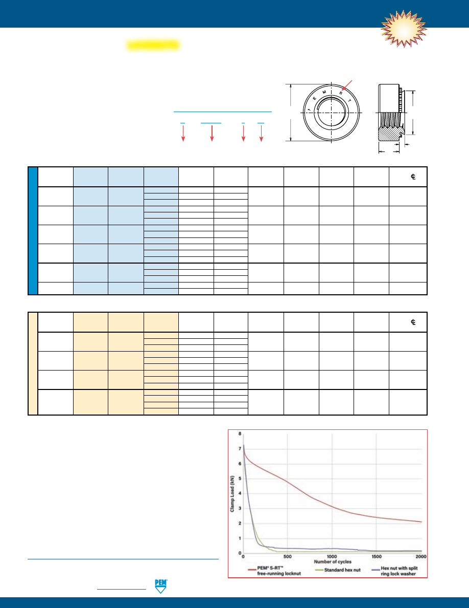
CL-6
PennEngineering •
www.pemnet.com
SELF-CLINCHING NUTS
U
NIF
IE
D
A
Rec.
Hole Size
Min. Dist
Thread
Type
Thread
Shank
(Shank)
Min. Sheet
In Sheet
C
E
T
Hole
CL
Size
Code
Code
Max.
Thickness (1)
+.003 –.000
Max.
±.010
±.010
To Edge
.112-40 0 .030 .030
(#4-40)
S RT440 1 .038 .040 .166 .165 .250 .070 .19
2
.054
.056
.138-32 0 .030 .030
(#6-32)
S RT632 1 .038 .040 .1875 .187 .280 .070 .22
2
.054
.056
.164-32 0 .030 .030
(#8-32)
S RT832 1 .038 .040 .213 .212 .310 .090 .27
2
.054
.056
.190-32 0 .030 .030
(#10-32)
SS RT032 1 .038 .040 .250 .249 .340 .090 .28
2
.054
.056
.250-20 0 .045 .047
(1/4-20)
S RT0420 1 .054 .056 .344 .343 .440 .170 .34
2
.087
.090
.313-18
S RT0518 1 .054 .056 .413 .412 .500 .230 .38
(5/16-18)
2 .087 .090
All dimensions are in inches.
ME
TR
IC
Thread
A
Rec.
Hole Size
Min. Dist
Size x
Type
Thread
Shank
(Shank)
Min. Sheet
In Sheet
C
E
T
Hole
CL
Pitch
Code
Code
Max.
Thickness (1)
+0.08
Max.
±0.25
±0.25
To Edge
0
0.77
0.8
M3 x 0.5
S RTM3 1 0.97 1 4.22 4.2 6.35 1.5 4.8
2
1.38
1.4
0
0.77
0.8
M4 x 0.7
S
RTM4
1
0.97
1
5.41
5.38
7.87
2
6.9
2
1.38
1.4
0
0.77
0.8
M5 x 0.8
SS
RTM5
1
0.97
1
6.35
6.33
8.64
2
7.1
2
1.38
1.4
00
0.89
0.92
M6 x 1
S
RTM6 0 1.15 1.2 8.75 8.73 11.18 4.08 8.6
1
1.38
1.4
2
2.21
2.29
All dimensions are in millimeters
S-RT™ FREE-RUNNING
Free-running locking feature allows screw to turn freely until clamp load is applied. If the tightening force is removed, these nuts no
longer provide any torsional resistance to rotation.
•
Resistant to vibrational loosening.
•
Back side of panel is flush or sub-flush for screw installation.
•
Locking feature reusability is not affected by
number of on/off cycles.
•
Uses same mounting hole and installation
tooling as standard S™ nuts.
•
Recommended for use in steel or aluminum
sheets HRB 80 / HB 150 or less.
NEW!
The graph represents the clamp load of the joint versus the
amount of cycles during transverse vibration testing for an
S-RT™ free-running locknut, a standard hex nut and a hex nut
with a split ring lock washer.
Testing conditions:
Transverse vibration testing.
M6 thread size nuts, average of 30 pieces.
Clamp load applied using metric property class 10.9 screws.
Nuts tested until loss of clamp load or 2,000 cycles is reached.
Type
Finish
PART NUMBER DESIGNATION
Thread
Size Code
Shank
Code
S - RT632 – 1
ZI
E
C
T
A
Clinching profile may vary.
“PEM RT” Stamp (Trademark)
LOCKNUTS
Details on PEM® RT™ vibration resistant thread technology
can be found on our web site at:
https://www.pemnet.com/files/design_info/techsheets/RT_Thread_Form.pdf
pem-html.html
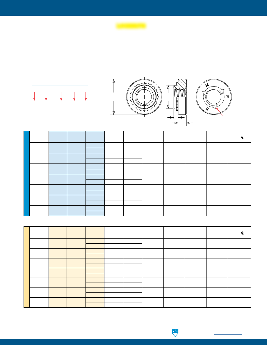
PennEngineering •
www.pemnet.com
CL-7
SELF-CLINCHING NUTS
SL™ TRI-DENT® PREVAILING TORQUE
Prevailing torque locking feature produces friction between threads of mated components thereby increasing the force needed to
tighten as well as loosen the nut. Prevailing torque locknuts provide essentially the same torque value regardless of the amount axial
load applied.
•
3 cycle locking performance.
(1)
•
Resistant to vibrational loosening.
•
Back side of panel is flush or sub-flush for screw installation.
•
Uses same mounting hole and installation tooling as standard S™ nuts.
•
Recommended for use in sheets HRB 80 / HB 150 or less.
ME
TR
IC
U
NIF
IE
D
A
Hole Size
Min. Dist.
Thread
Type
Thread
Shank
(Shank)
Min. Sheet
In Sheet C
E T Hole
C/L
Size
Code
Code
Max.
Thickness +.003 –.000
Max.
±.010
±.010
To Edge
.112-40
SL 440
1 .038 .040
.166 .165 .250 .070 .19
(#4-40)
2 .054 .056
.138-32
SL 632
1 .038 .040
.1875 .187 .280 .070 .22
(#6-32)
2 .054 .056
.164-32
SL 832
1 .038 .040
.213 .212 .310 .090 .27
(#8-32)
2 .054 .056
.190-32
SL 032
1 .038 .040
.250 .249 .340 .090 .28
(#10-32)
2 .054 .056
.250-20
SL 0420
1 .054 .056
.344 .343 .440 .170 .34
(1/4-20)
2 .087 .091
.313-18
SL 0518
1 .054 .056
.413 .412 .500 .230 .38
(5/16-18) 2 .087 .091
.375-16
SL 0616
1 .087 .090
.500 .499 .625 .270 .44
(3/8-16) 2 .120 .125
Thread
A
Hole Size
Min. Dist
Size x
Thread
Shank
(Shank)
Min. Sheet
In Sheet
C
E
T
Hole
C/L
Pitch
Type
Code
Code
Max.
Thickness
+0.08
Max.
±0.25
±0.25
To Edge
1 0.98 1
M3 x 0.5 SL M3
2 1.38 1.4
4.22 4.2 6.35 1.5 4.8
1 0.98 1
M3.5 x 0.6 SL M3.5
2 1.38 1.4
4.75 4.73 7.11 1.5 5.6
1 0.98 1
M4 x 0.7 SL M4
2 1.38 1.4
5.41 5.38 7.87 2 6.9
1 0.98 1
M5 x 0.8 SL M5
2 1.38 1.4
6.35 6.33 8.64 2 7.1
1 1.38 1.4
M6 x 1 SL M6
2 2.21 2.3
8.75 8.73 11.18 4.08 8.6
M8 x 1.25
SL
M8
1 1.38 1.4
10.5 10.47 12.7 5.47 9.7
2 2.21 2.3
M10 x 1.5
SL
M10
1 2.21 2.29
14 13.97 17.35 7.48 13.5
2 3.05 3.18
(1) Achieved using steel socket head cap screws,180 ksi / property class 12.9 with standard finish of thermal oxide and light oil.
All dimensions are in inches.
All dimensions are in millimeters.
Type
S
L – 632 – 1
ZI
Thread
Size Code
Shank
Code
Locking
PART NUMBER DESIGNATION
Finish
PEM TRI-DENT®
Locking Feature
(shape and position may vary)
E
C
A
T
Clinching profile may vary.
LOCKNUTS
pem-html.html
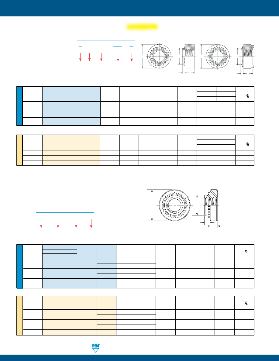
CL-8
PennEngineering •
www.pemnet.com
SELF-CLINCHING NUTS
ME
TR
IC
U
NIF
IE
D
All dimensions are in millimeters.
Type
T
1
T
2
Thread
A
Hole Size
Min. Dist.
Size x
Non-
Self-
Thread
(Shank)
Min. Sheet
In Sheet
C
E
Non-locking Self-locking
Hole
C/L
Pitch
Locking
Locking (1)
Code
Max.
Thickness
+0.13
Max.
±0.25
±0.13
±0.25
To Edge
M6
x 1
—
HNL
M6
1.48
1.48
8.75
8.72
12.7
5
10
M8
x 1.25
—
HNL
M8
1.48
1.48
10.5
10.47
14.6
6.3
11
M10
x 1.5
H
HNL
M10
1.48
1.48
12.7
12.67
16.5
7.9
12
All dimensions are in inches.
Type
Hole
Size
T
1
T
2
A
In Sheet
Min. Dist.
Thread
Non-
Self-
Thread
(Shank)
Min. Sheet
+.005
C
E
Non-locking Self-locking
Hole
C/L
Size
Locking
Locking (1)
Code
Max.
Thickness
-.000
Max.
±.010
±.005
±.010
To Edge
.250-20
— HNL 0420 .058 .058 .344 .343 .500
.189
.380
(1/4-20)
.313-18
— HNL 0518 .058 .058 .413 .412 .575
.240
.420
(5/16-18)
.375-16 H HNL 0616 .058 .058 .500 .499 .650
.300
.480
(3/8-16)
(1) During installation, the projections on the heads of HNL self-locking nuts may be flattened. This is not detrimental in any way and will not affect self-
locking or self-clinching performance.
•
Meets torque requirements for
IFI 100/107 Grade B (unified)
and ANSI B18.16.1M (metric)
locknuts.
•
H nut is recommended for use
in sheets HRB 80 / HB 150 or
less.
•
HNL nut is recommended for
use in sheets HRB 60 / HB
107 or less.
H™ NUTS AND HNL™ PREVAILING TORQUE
Clinching profile may vary.
Type
H
– 0616
ZI
H N
L – 0616
LZ
Thread
Size Code
Finish
Locking
PART NUMBER DESIGNATION
Not
Heat-
treated
E
T
1
C
A
Type H
T
2
C
A
E
Type HNL
Type
SH – 0420 – 1
X
Shank
Code
Thread
Size Code
Finish
PART NUMBER DESIGNATION
U
NIF
IE
D
SH™ HARD PANEL NUTS
•
Installs into harder, high strength steel materials (high strength
steel sheets up to 975MPa tensile strength).
•
Hardened nut material provides stronger thread strength.
Type
A
Min.
Hole
Size
Min.
Dist
Thread
Fastener Material
Thread
Shank
(Shank)
Sheet
in Sheet
C
E
T
Hole
C/L
Size
Hardened Alloy Steel
Code Code Max. Thickness
(1)
+.003 –.000
Max.
±.010
±.010
To Edge
.250-20
SH 0420
1 .054 .056
.344 .343 .440 .170 .34
(1/4-20)
2 .087 .090
.313-18
SH 0518
1 .054 .056
.413 .412 .500 .230 .38
(5/16-18)
2 .087 .090
.375-16
SH
0616 1 .087 .090 .500 .499 .623 .270 .44
(3/8-16)
All dimensions are in inches.
(Clinching profile may vary)
Due to manufacturing procedure, parts
may have a counterbore at shank end.
C
E
A
T
(1) For maximum performance, we recommend that you use the maximum shank length for your sheet thickness.
All dimensions are in millimeters.
ME
TR
IC
Thread
Type
A
Min.
Hole
Size
Min.
Dist
Size x
Fastener Material
Thread
Shank
(Shank)
Sheet
in Sheet
C
E
T
Hole
C/L
Pitch
Hardened Alloy Steel
Code Code Max. Thickness
(1)
+0.08
Max.
±0.25
±0.25
To Edge
M6 x 1
SH
M6
1 1.38 1.4
8.75 8.73 11.18 4.08 8.6
2
2.21
2.29
M8 x 1.25
SH
M8
1 1.38 1.4
10.5 10.47 12.7 5.47 9.7
2
2.21
2.29
M10 x 1.5
SH
M10
1
2.21
2.29
14
13.97
17.35
7.48
13.5
LOCKNUTS
pem-html.html
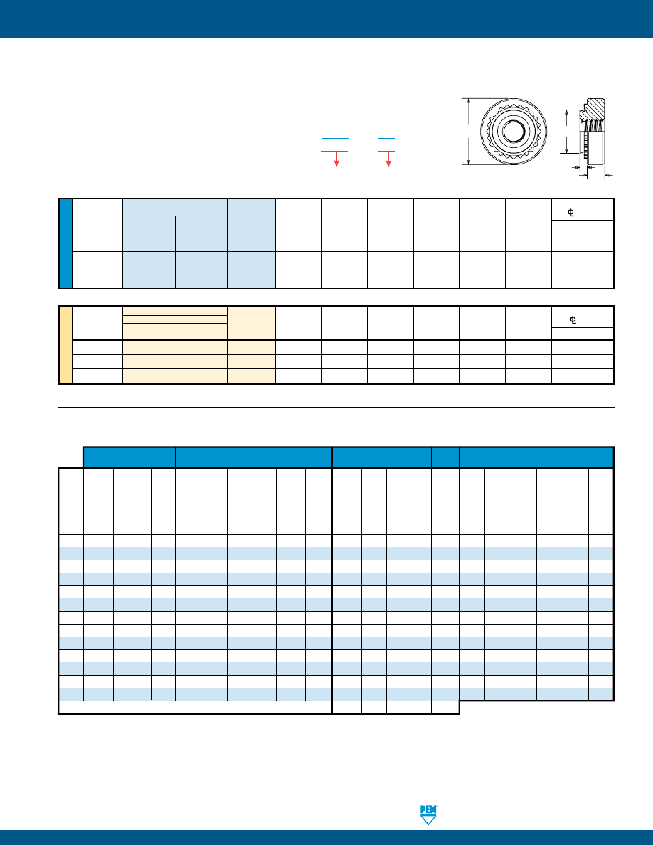
PennEngineering •
www.pemnet.com
CL-9
SELF-CLINCHING NUTS
SMPS™/SMPP™ NUTS
•
Installs into sheets as thin as .025”/ 0.64 mm.
•
Reduced outer dimensions and thinner sheet
capabilities compared to Type S/SP thread sizes.
•
SMPS nut is recommended for use in sheets
HRB 70 / HB 125 or less.
•
SMPP nut is recommended for use in stainless steel
sheets HRB 90 / HB 192 or less.
Type
SMPS – 440
SMPP – 440
Thread
Size Code
PART NUMBER DESIGNATION
C
A
T
E
Clinching profile may vary.
U
NIF
IE
D
Type
Min. Dist. Hole
Fastener Material
A
Hole Size
CL
To Edge
Thread
Hardened
Thread
(Shank)
Min. Sheet
In Sheet
C
E
T
Size
Stainless Steel
Stainless Steel Code Max. Thickness
+.003 –.000
Max.
±.010
±.010
SMPS SMPP
.086-56
SMPS
SMPP
256
.024
.025
.136
.135
.220
.065 .15 .16
(#2-56)
.112-40
SMPS
SMPP
440
.024
.025
.166
.165
.220
.065 .17 .20
(#4-40)
.138-32
SMPS
SMPP
632
.024
.025
.187
.186
.252
.065 .20 .22
(#6-32)
All dimensions are in inches.
ME
TR
IC
Type
Min. Dist. Hole
Thread Fastener Material
A
Hole Size
CL
To Edge
Size x
Hardened
Thread
(Shank)
Min. Sheet
In Sheet
C
E
T
Pitch
Stainless Steel
Stainless Steel Code Max. Thickness
+0.08 Max. ±0.25 ±0.25
SMPS SMPP
M2.5 x 0.45
SMPS
SMPP
M2.5
0.61
0.64
3.8
3.79
5.6
1.4
3.7
3.9
M3 x 0.5
SMPS
SMPP
M3
0.61
0.64
4.24
4.22
5.6
1.4
4.3
5.1
M3.5 x 0.6
SMPS
SMPP
M3.5
0.61
0.64
4.75
4.73
6.4
1.4
5.1
5.5
All dimensions are in millimeters.
Threads
Fastener Materials
Standard Finishes Optional
For use in Sheet Hardness (8)
Finish
Meets
Torque
Zinc
Requirements
Plated,
for
IFI
100/
5µm,
107 Grade B
Age
Passivated Zinc
Colorless
Zinc
Internal
(unified) and 3 Cycle
300
Hardened
and/or
Plated,
Plus
Plated,
ASME B1.1
ANSI B18.
Locking Hardened Series
A286
Tested
5µm,
Sealant/ No
5µm,
HRC 30/ HRB 90/ HRB 80/ HRB 70/ HRB 60/ HRB 50/
2B/ASME 16.1M (metric) Perfor- Carbon Stainless
Carbon Hardened Stainless per ASTM Colorless Lubricant Finish Yellow
HB 277
HB 192
HB 150
HB 125
HB 107
HB 82
Type B1.13M, 6H
Locknuts
mance
Steel
Steel
Aluminum Steel Alloy Steel Steel
A380
(4)
(4)
(3)
(4)
or less
or less
or less
or less
or less
or less
S
• • • • •
SS
• • • • •
CLS
• • • •
CLSS
• • • •
CLA
• •
•
(2)
•
H
• • • • •
SP
• • • •
S-RT
• • • • •
SL
• • • • •
HNL
• • • • •
SH
• •
•
(5)
•
SMPS
• • • •
SMPP
• • • •
Part number codes for finishes
None
ZI LZ
X
ZC
(1) Special order with additional charge.
(2) Part numbers for aluminum nuts have no plating suffix.
(3) Unplated threads are sized to accept a basic go gauge after
.00025” / 0.0064 mm plating.
(4) See PEM Technical Support section of our web site for related
plating standards and specifications.
MATERIAL AND FINISH SPECIFICATIONS
(5) With rust preventative oil.
(6) Panel material should be in the annealed condition.
(7) Fasteners should not be installed adjacent to bends or other highly cold-
worked areas.
(8) HRB - Hardness Rockwell “B” Scale. HRC - Hardness Rockwell “C” Scale.
HB - Hardness Brinell.
pem-html.html
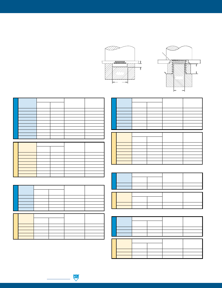
CL-10
PennEngineering •
www.pemnet.com
SELF-CLINCHING NUTS
ME
TR
IC
ME
TR
IC
U
NIF
IE
D
U
NIF
IE
D
1.
Prepare properly sized mounting hole in sheet.
Do not perform any secondary operations such as
deburring.
2.
Place fastener into the anvil hole and place the
mounting hole (preferably the punch side) over
the shank of the fastener as shown in diagram to
the right.
3.
With installation punch and anvil surfaces parallel,
apply squeezing force until the head of the nut
comes into contact with the sheet material.
Anvil Dimensions (in.)
Thread
A P
Anvil Part
Punch Part
Code
±.002 ±.005
Number
Number
256/440/RT440
.267
.045
975200034
975200048
632/RT632
.298
.045
975200035
975200048
832/RT832
.330
.070
975200036
975200048
024/032/RT032
.361
.070
975200037
975200048
1224
.415 .080 975200786300 975200048
0420/RT0420
.454
.150
975200038
975200048
0518/RT0518
.517
.200
975200039
975200048
0616
.280 .250 975200045
(1)
975200048
0720
.338 .295
8020361
(1)
975200901400
0813
.375 .345 975200900300
(1)
975200901400
CLA™ NUTS
Anvil Dimensions (in.)
Thread
A P
Anvil Part
Punch Part
Code
±.002 ±.005 Number Number
256/440
.267
.045
975200034
975200048
632
.298
.045
975200035
975200048
832
.330
.070
975200036
975200048
024/032
.392
.140
975200782300
975200048
0420
.454
.150
975200038
975200048
PEMSERTER®
Installation Tooling
(1) Large nut anvils use protrusion to locate part instead of counterbore.
Anvil Dimensions (mm)
Thread
A P
Anvil Part
Punch Part
Code
±0.05 ±0.13
Number
Number
M2/M3/RTM3
6.78
1.14
975200034
975200048
M3.5
7.57
1.14
975200035
975200048
M4/RTM4
8.38
1.78
975200036
975200048
M5/RTM5
9.17
1.78
975200037
975200048
M6/RTM6
11.53
3.81
975200038
975200048
M8
13.08 5.08
975200039 975200048
M10
7.62 6.35
8005682
(1)
975200901400
M12
9.53 8.76 975200900300
(1)
975200901400
U
NIF
IE
D
Anvil Dimensions (mm)
Thread
A P
Anvil Part
Punch Part
Code
±0.05 ±0.13 Number Number
M3
6.78
1.14
975200034
975200048
M3.5
7.57
1.14
975200035
975200048
M4
8.38
1.78
975200036
975200048
M5
9.96
3.56
975200782300 975200048
M6
11.53
3.81
975200038
975200048
ME
TR
IC
SMPS™ NUTS
Anvil Dimensions (in.)
Thread
A P
Anvil Part
Punch Part
Code
±.002 ±.005 Number Number
256/440
.236
.045
975200904300
975200048
632
.267
.045
975200034
975200048
U
NIF
IE
D
Anvil Dimensions (mm)
Thread
A P
Anvil Part
Punch Part
Code
±0.05 ±0.13 Number Number
M2.5/M3
5.99
1.14
975200904300
975200048
M3.5
6.78
1.14
975200034
975200048
ME
TR
IC
SL™ NUTS
Anvil Dimensions (in.)
Thread
A P
Anvil Part
Punch Part
Code
±.002 ±.005 Number Number
440
.267
.045
975200034
975200048
632
.298
.045
975200035
975200048
832
.330
.070
975200036
975200048
032
.361
.070
975200037
975200048
0420
.454
.150
975200038
975200048
0518
.515
.200
975200039
975200048
0616
.280
.250
975200045
(1)
975200048
Anvil Dimensions (mm)
Thread
A P
Anvil Part
Punch Part
Code
±0.05 ±0.13 Number Number
M3
6.78
1.14
975200034
975200048
M3.5
7.57
1.14
975200035
975200048
M4
8.38
1.78
975200036
975200048
M5
9.17
1.78
975200037
975200048
M6
11.53
3.81
975200038
975200048
M8
13.08
5.08
975200039
975200048
M10
7.62
6.35
8005682
(1)
975200901400
H™/HNL™ NUTS
Anvil Dimensions (in.)
Thread
A P
Anvil Part
Punch Part
Code
±.002 ±.005 Number Number
0420 .517 .200 975200039 975200048
0518
.220
.250
975200783300
(1)
975200048
0616 .280 .250 975201240
(1)
8003076
U
NIF
IE
D
Anvil Dimensions (mm)
Thread
A P
Anvil Part
Punch Part
Code
±0.05 ±0.13 Number Number
M6
13.13
5.08
975200039
975200048
M8 5.59 6.35 975200783300
(1)
975200048
M10 7.62 6.35 8005682
(1)
8003076
ME
TR
IC
INSTALLATION - S™/SL™/SMPS™/SS™/CLS™/CLSS™/CLA™/S-RT™/H™/HNL™ NUTS
COUNTERBORE ANVIL
Thread Sizes #2-56 to 5/16
and M2 to M8
PROTRUSION ANVIL
(1)
CLS/S/SL/S-RT Thread Sizes 3/8, 7/16, 1/2, M10 and M12
H/HNL Thread Sizes 5/16, 3/8, M8 and M10
45˚ x .050”/
1.27 mm
Max.
R .015” /
0.381 mm
Max.
A
P
PUNCH
ANVIL
PUNCH
ANVIL
A
P
CLS™/CLSS™/S™/SS™/S-RT™ NUTS
pem-html.html
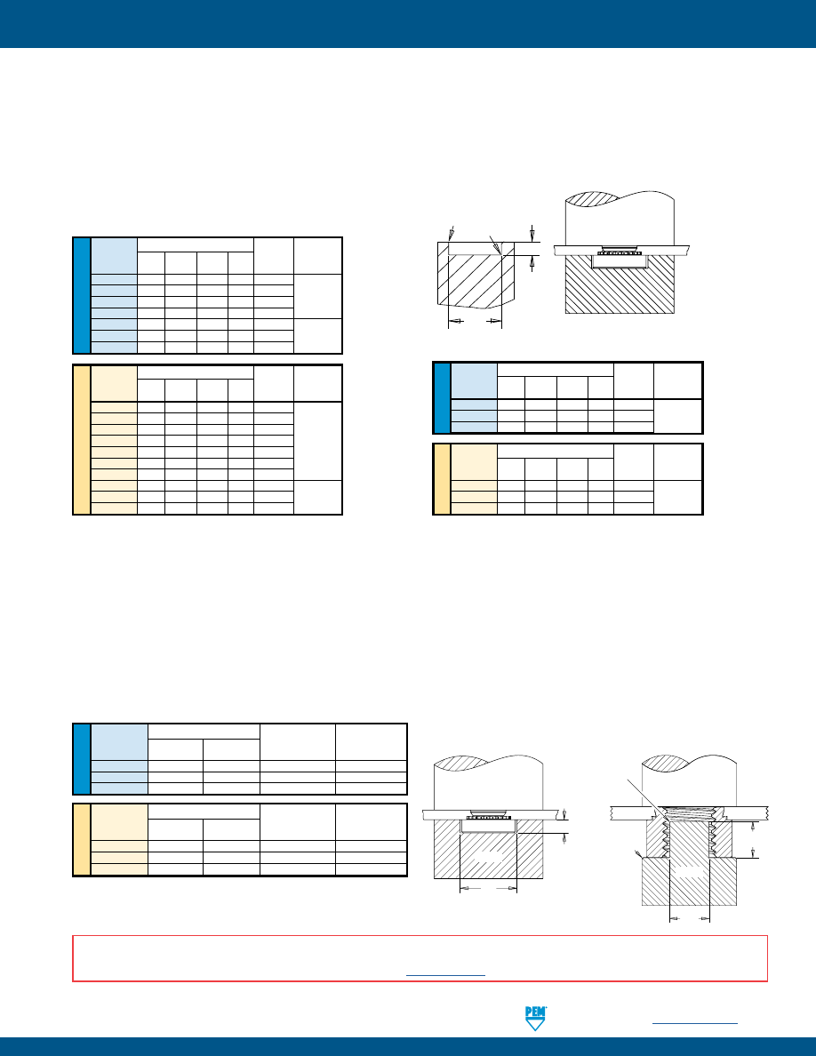
PennEngineering •
www.pemnet.com
CL-11
SELF-CLINCHING NUTS
1.
Prepare properly sized mounting hole in sheet. Do not perform any secondary operations such as deburring.
2.
Place fastener into the recommended counterbore anvil hole and place the mounting hole (preferably the punch side) over the
shank of the fastener as shown in diagram.
3.
With installation punch and anvil surfaces parallel, apply squeezing force until the head of the nut comes into contact with the
sheet material.
RECOMMENDED
COUNTERBORE ANVIL
R
R
1
P
A
INSTALLATION - SP™/SMPP™ NUTS
(1)
(1) For best results, we recommend using the installation punch and anvil shown. Deviations from recommended installation tooling may result in sheet
distortion and reduced performance.
NOTE:
Variations in hole preparation, installation tooling, installation force, and sheet material type, thickness, and hardness will affect both performance
and tooling life.
PUNCH
ANVIL
U
NIF
IE
D
Anvil Dimensions (in.)
Anvil Punch
Thread
A
P +.000
R
R
1
Part Part
Code ±.002 –.001 Max. +.005 Number Number
440 .255 .064 .010 .005 8012821
632 .286 .064 .010 .005 8012822 975200048
832
.317 .082 .010 .005 8012823
024/032 .348 .082 .010 .005 8012824
0420 .443 .163 .010 .005 8012825
0518 .505 .230 .010 .005 8015359 8003076
0616/0624 .570 .263 .010 .005 8015863
ME
TR
IC
Anvil Dimensions (mm)
Anvil Punch
Thread A
P
R
R
1
Part Part
Code ±0.05 –0.03 Max. +0.13 Number Number
M2 6.48 1.63 0.25 0.13 8012821
M2.5-0 6.48 1.42 0.25 0.13 8019477
M2.5-1,-2 6.48 1.63 0.25 0.13 8012821
M3 6.48 1.63 0.25 0.13 8012821 975200048
M3.5 7.26 1.63 0.25 0.13 8012822
M4 8.05 2.08 0.25 0.13 8012823
M5 8.84 2.08 0.25 0.13 8012824
M6 11.25 4.14 0.25 0.13 8012825
M8 12.83 5.41 0.25 0.13 8015360 8003076
M10 17.58 7.47 0.25 0.13 8015886
PEMSERTER® Installation Tooling
ME
TR
IC
U
NIF
IE
D
INSTALLATION - SH™ NUTS
1.
Prepare properly sized mounting hole in sheet. Do not perform any secondary operations such as deburring.
2.
Place fastener into the anvil hole and place the mounting hole
(preferably the punch side)
over the shank of the fastener as shown in
diagram to the right.
3.
With installation punch and anvil surfaces parallel, apply squeezing force until the head of the nut comes into contact with the sheet material.
COUNTERBORE ANVIL
Thread Sizes 1/4-20 to 5/16 and M5 to M8
PROTRUSION ANVIL
Thread Sizes 3/8 and M10
Anvil Dimensions (in.)
Thread
A P
Anvil Part
Punch Part
Code
±.002 ±.005 Number Number
0420
.454
.150
975200038
975200048
0518 .517 .200 975200039 975200048
0616
.280
.250
8020084
(1)
9752000901400
Anvil Dimensions (mm)
Thread
A P
Anvil Part
Punch Part
Code
±0.05 ±0.13 Number Number
M6
11.53
3.81
975200038
975200048
M8 13.13 5.08 975200039 975200048
M10 7.62 6.35 8005682
(1)
975200901400
(1) Large nut anvils use protrusion to locate part instead of counterbore.
PEMSERTER® Installation Tooling
45˚ x .050”/
1.27 mm
Max.
R .015” /
0.381 mm
Max.
A
P
PUNCH
ANVIL
PUNCH
ANVIL
A
P
U
NIF
IE
D
Anvil Dimensions (in.)
Anvil Punch
Thread
A
P +.000
R
R
1
Part Part
Code ±.002 –.001 Max. +.005 Number Number
256
.223 .060 .010 .005 8020023
440 .233 .060 .010 .005 8021386 975200048
632
.255 .060 .010 .005 8020024
ME
TR
IC
Anvil Dimensions (mm)
Anvil Punch
Thread
A P R R
1
Part Part
Code ±0.05 –0.03 Max. +0.13 Number Number
M2.5 5.66 1.27 0.25 0.13 8020025
M3
5.9 1.27 0.25 0.13 8021474 975200048
M3.5 6.48 1.27 0.25 0.13 8020026
SP™ NUTS
SMPP™ NUTS
INSTALLATION NOTES
•
For best results we recommend using a PEMSERTER® press for installation of PEM self-clinching fasteners. Please check our website for more information.
•
Visit the Animation Library on our website to view the installation process
for select products
.
pem-html.html
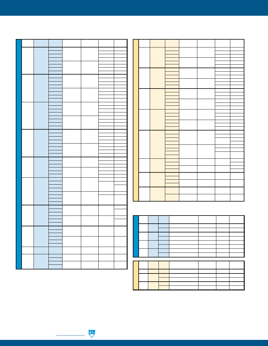
CL-12
PennEngineering •
www.pemnet.com
SELF-CLINCHING NUTS
ME
TR
IC
U
NIF
IE
D
Type
Thread
Shank
Test Sheet
Installation
Pushout
Torque-out
Code
Code
Material
(lbs.)
(lbs.)
(in. lbs.)
0
63 8
1 5052-H34
90 10
2 Aluminum
1500-2000
170 13
S
256
3
170 13
CLS
348
0
105 13
440
1 Cold-rolled
2500-3500
125 15
2 Steel
230 18
3
230 18
0
63 16
1 5052-H34
95 17
2 Aluminum
2500-3000
190 22
S 3
190 22
CLS
632
0
110 16
1 Cold-rolled
3000-6000
130 20
2 Steel
275 28
3
275 28
0
68 21
1 5052-H34
105 23
2 Aluminum
2500-3000
220 35
S 3
220 35
CLS
832
0
110 26
1 Cold-rolled
145 35
2 Steel
4000-6000
285 45
3
285 45
0
68 26
1 5052-H34
110 32
2 Aluminum
2500-3500
190 50
SS 024 3
225 50
CLSS 032 0
120 32
1 Cold-rolled
180 40
2 Steel
4000-9000
320 60
3
320 60
1
5052-H34
120 63
2
Aluminum
2500-6500 285
70
S 3
285 70
CLS
1224
1
Cold-rolled
200 74
2
Steel
5000-6500 350 80
3
350 80
0
220 70
1 5052-H34
90
2 Aluminum
4000-7000
360
S 3
125
CLS
0420
0
315 115
1 Cold-rolled
6000-8000
2 Steel
400 150
3
1
5052-H34
120
2
Aluminum
4000-7000 380
160
S 0518 3
CLS 0524 1
Cold-rolled
165
2
Steel
6000-8000 420
180
3
1
5052-H34
2
Aluminum
5000-8000 400 270
S 0616 3
CLS 0624 1
Cold-rolled
2
Steel
7000-11000 460 320
3
S 0720 1 Cold-rolled
9000-13000 450 340
Steel
1 5052-H34
S 0813 2 Aluminum
7000-9000 475 350
CLS 0820 1 Cold-rolled
2 Steel
10000-15000 1050 735
Type
Thread
Shank
Test Sheet
Installation
Pushout
Torque-out
Code Code Material (kN) (N) (N•m)
0
280 0.9
1
5052-H34
6.7-8.9 400 1.13
S M2 2
Aluminum
750 1.47
CLS M2.5 0
470 1.47
M3 1
Cold-rolled
11.2-15.6 550 1.7
2
Steel
1010 2.03
0
280 1.8
1
5052-H34
11.2-13.5 400 1.92
S
M3.5
2
Aluminum
840 2.5
CLS
0
480 1.8
1
Cold-rolled
13.4-26.7 570 2.3
2
Steel
1210 2.3
0
300 2.37
1
5052-H34
11.2-13.4 470 2.6
S
M4
2
Aluminum
970 4
CLS
0
490 2.95
1
Cold-rolled
18-27 645 4
2
Steel
1250 5.1
0
300 3
1
5052-H34
11.2-15.6 480 3.6
SS
M5
2
Aluminum
845 5.7
CLSS
0
530 3.6
1 Cold-rolled 18-38 800 4.5
2 Steel 1112 6.8
00
750 6.5
0
970 7.9
1
5052-H34
18-32
1580
10.2
S
M6
2
Aluminum
14.1
CLS
00
900 10
0
1380 13
1
Cold-rolled
27-36
1760 17
2
Steel
1 5052-H34
18-32 1570
13.6
S
M8
2 Aluminum
18.1
CLS
1 Cold-rolled
27-36 1870
18.7
2 Steel
20.3
1 5052-H34
22-36 1760 32.7
S
M10
2 Aluminum
CLS
1
Cold-rolled
32-50 2020 36.2
2
Steel
1 5052-H34 31-40 2113 39.5
Aluminum
S M12
1 Cold-rolled 44-67 4670 83.1
Steel
S™/CLS™/CLSS™ NUTS
(1) Published installation forces are for general reference. Actual set-up and confirmation of complete installation should be made by observing proper
seating of fastener as described in the installation steps. Other performance values reported are averages when all proper installation parameters
and procedures are followed. Variations in mounting hole size, sheet material, and installation procedure may affect performance. Performance
testing this product in your application is recommended. We will be happy to provide technical assistance and/or samples for this purpose.
PERFORMANCE DATA
(1)
CLA™ NUTS
U
NIF
IE
D
Type
Thread Shank
Test Sheet
Installation
Pushout
Torque-out
Code
Code
Material
(lbs.)
(lbs.)
(in. lbs.)
CLA 440 1 5052-H34 Aluminum
800 - 1500
100
6
2
5052-H34 Aluminum
800 - 1500
120
9
CLA 632
1
5052-H34 Aluminum
1000 - 1500
110
21
2
5052-H34 Aluminum
1200 - 1700
155
24
CLA 832
1
5052-H34 Aluminum
1000 - 1500
120
27
2
5052-H34 Aluminum
1300 - 1800
170
29
CLA 032
1
5052-H34 Aluminum
1700 - 2200
130
34
2
5052-H34 Aluminum
2600 - 3100
200
50
ME
TR
IC
Type
Thread Shank
Test Sheet
Installation
Pushout
Torque-out
Code Code
Material
(kN)
(N)
(N•m)
CLA M2
2
5052-H34 Aluminum
3.56 - 6.67
500
0.4
CLA M3
1
5052-H34 Aluminum
3.56 - 6.67
445
0.68
2
5052-H34 Aluminum
3.56 - 6.67
534
1.02
CLA M4
1
5052-H34 Aluminum
4.45 - 6.67
534
3.05
2
5052-H34 Aluminum
5.78 - 8.01
756
3.27
pem-html.html
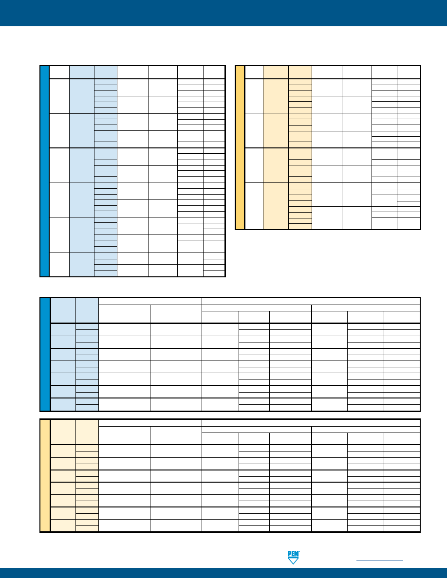
PennEngineering •
www.pemnet.com
CL-13
SELF-CLINCHING NUTS
S-RT™ NUTS
PERFORMANCE DATA
U
NIF
IE
D
Type
Thread
Shank
Test Sheet
Installation
Pushout
Torque-out
Code
Code
Material
(lbs.)
(lbs.)
(in. lbs.)
0
5052-H34
63 8
1
Aluminum 1500-2000 90
10
S RT440 2
170 13
0
Cold-rolled 105 13
1
Steel 2500-3500 125 15
2
230
18
0
5052-H34
63 16
1
Aluminum 2500-3000 95
17
S RT632 2
190 22
0
Cold-rolled 110 16
1
Steel 3000-6000 130 20
2
275
28
0
5052-H34 68 21
1
Aluminum 2500-3000 105
23
S RT832 2
220 35
0
Cold-rolled
110 26
1
Steel 4000-6000 145 35
2
285
45
0
5052-H34
68 26
1
Aluminum 2500-3500 110
32
SS RT032 2
190 50
0
Cold-rolled
120 32
1
Steel 4000-9000 180 40
2
320
60
0
5052-H34 220 70
1
Aluminum 4000-7000 360 90
S RT0420 2
125
0
Cold-rolled
315 115
1
Steel 6000-8000 400 150
2
1
5052-H34 4000-7000 380 120
S RT0518 2 Aluminum
160
1
Cold-rolled 6000-8000 420 165
2
Steel
180
ME
TR
IC
Type
Thread
Shank
Test Sheet
Installation
Pushout
Torque-out
Code
Code
Material
(kN)
(N)
(N•m)
0
5052-H34
280 0.9
1
Aluminum 6.7-8.9 400 1.13
S RTM3 2
750 1.47
0
Cold-rolled
470 1.47
1
Steel 11.2-15.6 550 1.7
2
1010
2.03
0
5052-H34
300 2.37
1
Aluminum 11.2-13.4 470 2.6
S RTM4 2
970 4
0
Cold-rolled
490 2.95
1
Steel 18-27 645 4
2
1250 5.1
0
5052-H34 300 3
1
Aluminum 11.2-15.6 480 3.6
SS RTM5 2
845 5.7
0
Cold-rolled
530 3.6
1
Steel 18-38 800 4.5
2
1112
6.8
00
750
6.5
0
5052-H34
18-32 970 7.9
1
Aluminum
1580 10.2
S RTM6 2
14.1
00
900
10
0
Cold-rolled
27-36 1380 13
1
Steel
1760 17
2
(1) 3 cycle locking performance. Max. on / Min. off torque for 1st through 3rd cycles.
SL™ NUTS
U
NIF
IE
D
Prevailing Torque Specifications (1)
Test Sheet Material
Thread Shank
Max. Torque
Min. Torque
5052-H34 Aluminum
Cold-rolled Steel
Code
Code
(1st thru 3rd)
(1st thru 3rd)
Installation
Pushout Torque-out Installation Pushout Torque-out
(in. lbs.)
(in. lbs.)
(lbs.)
(lbs.)
(in. lbs.)
(lbs.)
(lbs.)
(in. lbs.)
440
1
5.75
0.4
1500 - 2000
90 10
2500 - 3500
125 15
2
170
13
230
18
632 1
10.5
0.8
2500 - 3000 95
17
3000 - 6000 130
20
2
190
22
275
28
832 1
18
1.2
2500 - 3000 105
23
4000 - 6000 145
35
2
220
35
285
45
032 1
21
1.65
2500 - 3000 110
32
4000 - 9000 180
40
2
190
50
250
60
0420 1
35 3.75
4000 - 7000 360
90
6000 - 9000 400
150
2
360
125
400
150
0518 1
53
4.75
4000 - 7000 380
120
6000 - 8000 420
165
2
380 160
420 180
0616 1
95
6.3
5000 - 8000 400
270
7000 - 11000 460
320
2
400 270
460 320
ME
TR
IC
Prevailing Torque Specifications (1)
Test Sheet Material
Thread
Shank
Max. Torque
Min. Torque
5052-H34 Aluminum
Cold-rolled Steel
Code
Code
(1st thru 3rd)
(1st thru 3rd)
Installation Pushout Torque-out Installation Pushout Torque-out
(N•m)
(N•m)
(kN) (N) (N•m) (kN) (N) (N•m)
M3
1
0.67
0.04
6.7 - 8.9
400 1.13
11.2 - 15.6
550 1.7
2
750
1.47
1010
2.03
M3.5 1
1.2
0.08
11.2 - 13.5 400
1.92 13.4 - 26.7 570 2.3
2
840
2.5
1210
2.3
M4 1
2.1
0.13
11.2 - 13.4 470
2.6
18 - 27 645 4
2
970
4
1250
5.1
M5 1
2.4
0.18
11.2 - 15.6 480
3.6
18 - 38 800 4.5
2
845
5.7
1112
6.8
M6 1
4
0.3
18 - 32 1580 10.2 27 - 36 1760 17
2
1580
14.1
1760
17
M8 1
6
0.5
18 - 32 1570 13.6 27 - 36 1870 18.7
2
1570
18.1
1870
20.3
M10 1
12
0.8
22 - 36 1760 32.7 32 - 50 2020 36.2
2
1760
32.7
2020
36.2
pem-html.html
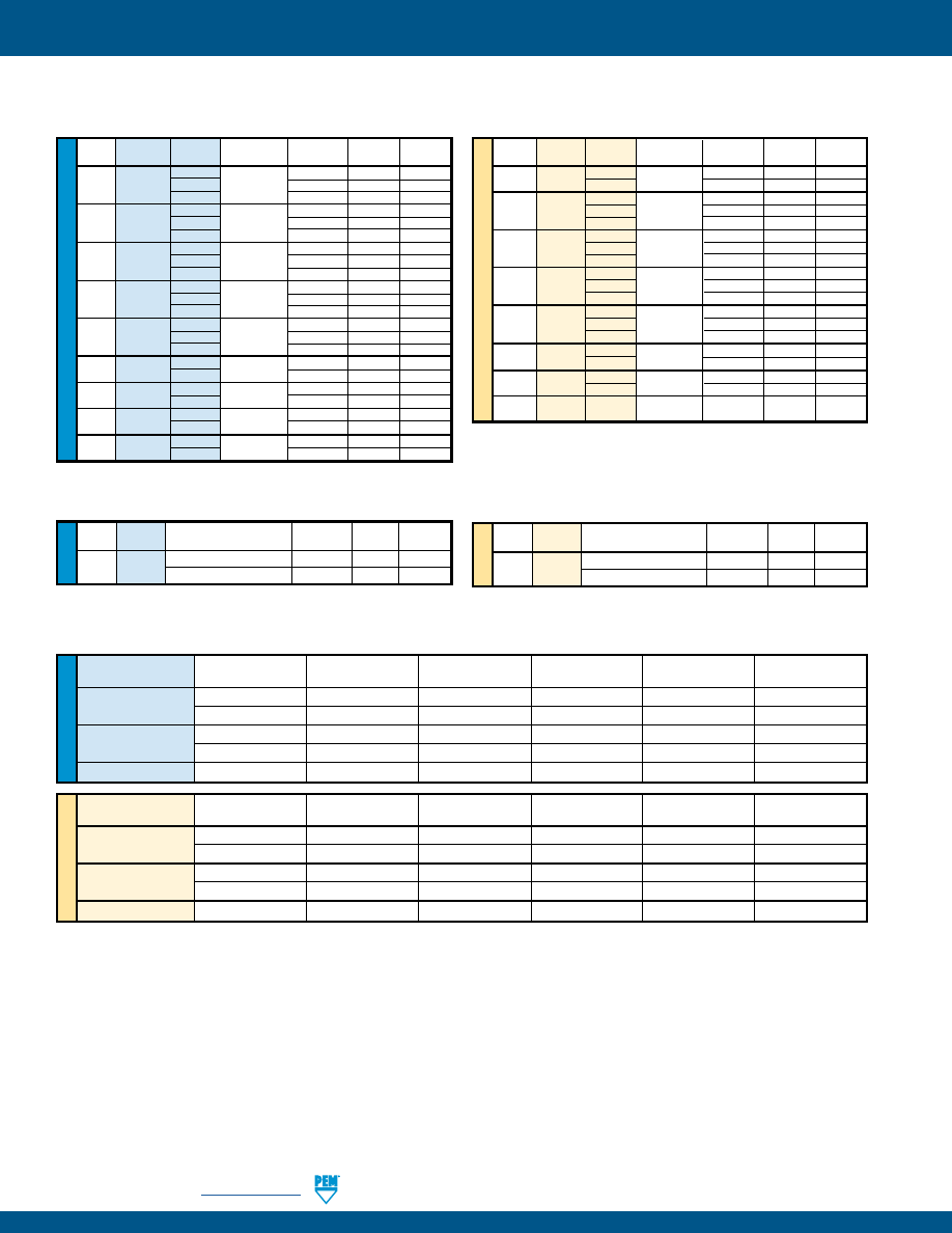
CL-14
PennEngineering •
www.pemnet.com
SELF-CLINCHING NUTS
PERFORMANCE DATA
ME
TR
IC
U
NIF
IE
D
Type
Thread
Shank
Test Sheet
Installation
Pushout
Torque-out
Code Code Material (kN) (N) (N•m)
SP
M2
1
304 Stainless
40 725 1.92
2 Steel 44.5 1290 2.03
0
35.6 575 1.58
SP M2.5 1
304 Stainless
40 725 1.92
2
Steel
44.5 1290 2.03
0
35.6 575 1.58
SP M3 1
304 Stainless
40 725 1.92
2
Steel
44.5 1290 2.03
0 40 645 3.38
SP M4 1
304 Stainless
44.5 800 4.18
2
Steel
49 1600 5.08
0 42.3 800 3.95
SP M5 1
304 Stainless
46.7 1025 5.08
2
Steel
51.2 1775 6.77
SP
M6
1
304 Stainless
60 2000 17
2 Steel 60 2600 19
SP M8 1
304 Stainless
66 2100 19
2
Steel
80 4500 23
SP M10 1
304 Stainless
80 2150 38
Steel
Type
Thread
Shank
Test Sheet
Installation
Pushout
Torque-out
Code
Code
Material
(lbs.)
(lbs.)
(in. lbs.)
0
304 Stainless
8000 130 14
SP 256 1
Steel
9000 165 17
2
10000 290 18
0
304 Stainless
8000 130 14
SP 440 1
Steel
9000 165 17
2
10000 290 18
0
304 Stainless
8500 140 18
SP 632 1
Steel
9500 170 24
2
10500 340 28
0
304 Stainless
9000 145 30
SP 832 1
Steel
10000 180 37
2
11000 360 45
0
304 Stainless
9500 180 35
SP 024/032 1
Steel
10500 230 45
2
11500 400 60
SP 0420
1
304 Stainless
13500 450 150
2 Steel 13500 600 170
SP 0518
1
304 Stainless
14800 470 170
2
Steel
14800 750 250
SP 0524
1
304 Stainless
14800
470
170
2 Steel 14800 750 250
SP 0616/0624 1
304 Stainless
16000 600 300
2
Steel 20000 700 370
SP™ NUTS
SH™ NUTS
U
NIF
IE
D
Thread
Shank
Test Sheet Thickness
Sheet
Installation
Pushout
Torque-out
Code
Code
and Material (in.)
Hardness HRC
(lbs.)
(lbs.)
(in. lbs.)
0420
1
.098” S700MC
23
11700
950
150
2
.098” S700MC
23
12900
1000
170
0518
1
.098” S700MC
23
12600
1050
265
2
.098” S700MC
23
12900
1100
265
0616
1
.098” S700MC
23
15300
1200
500
ME
TR
IC
Thread
Shank
Test Sheet Thickness
Sheet
Installation
Pushout
Torque-out
Code
Code
and Material (mm)
Hardness HRC
(kN)
(N)
(N•m)
M6
1
2.5 mm S700MC
23
52.1
4200
17
2
2.5 mm S700MC
23
57.4
4500
19
M8
1
2.5 mm S700MC
23
56.1
4600
30
2
2.5 mm S700MC
23
57.4
4900
30
M10
1
2.5 mm S700MC
23
71.2
5400
56
ME
TR
IC
U
NIF
IE
D
Type
Thread
Test Sheet Thickness
Installation
Pushout
Torque-out
Code
and Sheet Material
(lbs.)
(lbs.)
(in. lbs.)
H
0616
.090” 5052-H34 Aluminum
4900
380
190
.088” Cold-rolled Steel
7400
460
240
Type
Thread
Test Sheet Thickness
Installation
Pushout
Torque-out
Code
and Sheet Material
(kN)
(N)
(N•m)
H
M10
2.29 mm 5052-H34 Aluminum 22 1760 21.5
2.24 mm Cold-rolled Steel 33 2020 27.1
H™ NUTS
pem-html.html
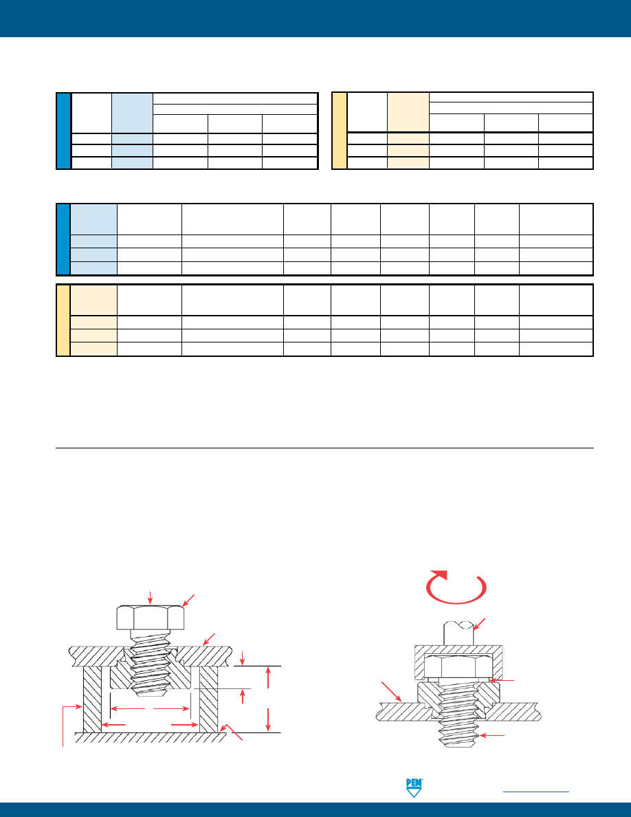
PennEngineering •
www.pemnet.com
CL-15
SELF-CLINCHING NUTS
PERFORMANCE DATA
SMPP™ NUTS
U
NIF
IE
D
Max.
Test Sheet Thickness
Sheet
Installation
Pushout Torque-out
Tensile
Test Bushing
Thread
Tightening Torque
and Material
Hardness
(lbs.)
(lbs.)
(in. lbs.)
Strength
Hole Size For
Code
(in. lbs.) (1) (2)
(in.)
HRB
(3)
(lbs.) (1) (2)
Pull Thru Tests (in.)
256
7.5
.029” 304 Stainless Steel
89
4500
50
10
640
.104
440
13
.029” 304 Stainless Steel
89
4500
75
15
850
.112
632
20
.029” 304 Stainless Steel
89
6000
75
20
1020
.138
ME
TR
IC
Max.
Test Sheet Thickness
Sheet
Installation
Pushout Torque-out
Tensile
Test Bushing
Thread
Tightening Torque
and Material
Hardness
(kN)
(N) (N•m)
Strength
Hole Size For
Code
(N•m) (1) (2)
(mm)
HRB
(3)
(kN) (1) (2)
Pull Thru Tests (mm)
M2.5
1.05
0.7 mm 304 Stainless Steel
89
20
200
1.35
3.05
3
M3
1.5
0.7 mm 304 Stainless Steel
89
20
300
1.85
3.63
3.5
M3.5
2.1
0.7 mm 304 Stainless Steel
89
27
300
1.9
4.25
4
ME
TR
IC
U
NIF
IE
D
Test Sheet Material
Type Thread
Cold-rolled Steel
Code
Installation Pushout Torque-out
(kN)
(N)
(N•m)
SMPS M2.5
6.7
156
1.13
SMPS M3
8
267
1.35
SMPS M3.5
8.8
289
1.58
Test Sheet Material
Type Thread
Cold-rolled Steel
Code
Installation Pushout Torque-out
(lbs.)
(lbs.)
(in. lbs.)
SMPS 256
1500
35
8
SMPS 440
1800
60
12
SMPS 632
2000
65
14
SMPS™ NUTS
(1) Head size is adequate to ensure failure in threaded area when tested with industry standard tensile bushing diameter.
(2) Tightening torque shown will induce preload of 70% of minimum axial strength assuming K or nut factor is equal to 0.20. In some applications tightening
torque may need to be adjusted based on the actual K value. All tightening torques shown are based on 180 ksi/ Property Class 12.9 screws. For lower
strength screws the tightening torque is proportionately less. For example, for 120 ksi screws, torque is 67% of value shown. For 900 MPa screws
(Property Class 9.8) torque value is 74% of value shown.
(3) Installation controlled by proper cavity depth in installation tooling.
PUSHOUT TEST
TORQUE-OUT TEST
Pushout tests shall be performed from the grip or shank side of the
installed fastener. An axial load shall be applied to the fastener as
shown using a hardened test screw, while evenly supporting the test
strip around the fastener. The typical position rate is .25” / 6.35 mm per
minute. Dimensions are identified per PEM Bulletins where “E” equals
head diameter and “T” (or “L”) equals head height. The pushout force
is measured using a force or compression tester with a range that will
cover the expected forces.
Torque-out tests shall be performed from the shoulder or head side
of the installed fastener. Torque shall be applied to the fastener in the
manner illustrated, using a hardened test screw and washer, while
firmly holding the test strip. Test screws should be of sufficient tensile
strength to resist thread stripping. A minimum of two screw threads
must extend beyond the fastener.
Applied Load
(Compression Tester)
Hardened Test Screw/Bolt
Grade 5 or better
Test Strip
Thickness > dash length
Surface of compression
force measuring gage
T
Hardened Support Bushing of sufficient wall thickness
to withstand compression loads applied.
E
E +.063” ±.01
+1.6 mm ±0.25
2T
(Min.)
Applied Torque
Driver for applied torque
Washer - Approximately 1 to
2 pitches. Thick enough to
prevent neck of screw from
contacting threads.
Hardened Test Screw/Bolt
Grade 5 or better
Test Strip
(parent material).
Held firmly in a vise.
pem-html.html
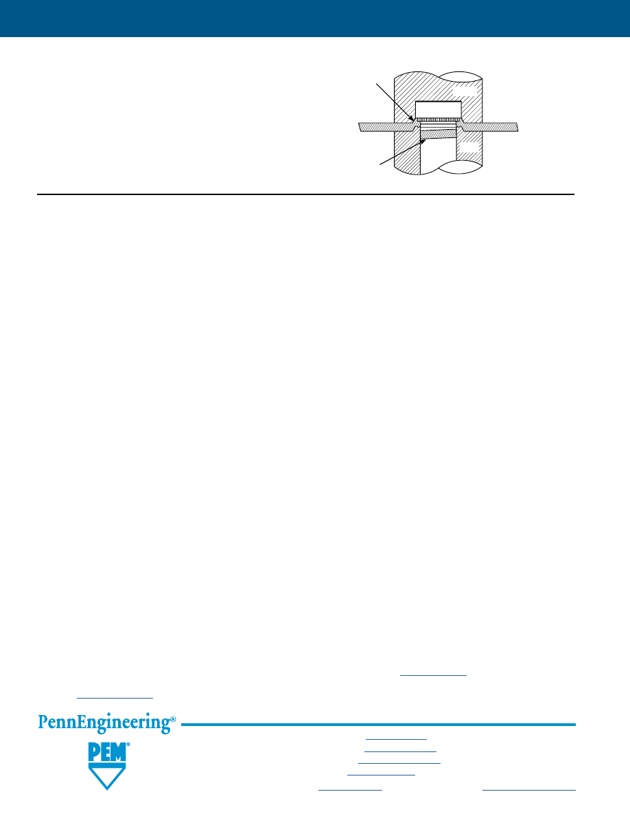
All PEM® products meet our stringent quality standards. If you require additional industry or other specific
quality certifications
, special procedures and/or part
numbers are required. Please contact your local sales office or representative for further information.
Regulatory
compliance information
is available in Technical Support section of our website. Specifications subject to change without notice. See our website for the
most current version of this bulletin.
North America:
Danboro, Pennsylvania USA
•
E-mail:
info@pemnet.com
•
Tel: +1-215-766-8853
•
800-237-4736 (USA)
Europe:
Galway, Ireland
•
E-mail:
europe@pemnet.com
•
Tel: +353-91-751714
Asia/Pacific:
Singapore
•
E-mail:
singapore@pemnet.com
•
Tel: +65-6-745-0660
Shanghai, China
•
E-mail:
china@pemnet.com
•
Tel: +86-21-5868-3688
Visit our PEMNET™ Resource Center at
www.pemnet.com
•
Technical support e-mail:
techsupport@pemnet.com
CL-16
“DOS”
DO
select the proper fastener material to meet corrosion requirements.
DO
make certain that panel material is in the annealed condition.
DO
make certain that hole punch is kept sharp to minimize work hardening around hole.
DO
provide mounting hole of specified size for each fastener.
DO
maintain the hole punch diameter to no greater than +.001”/.025 mm over the minimum recommended mounting hole for type SP
nuts into stainless steel sheets.
DO
install fastener into hole punch side of sheet.
DO
make certain that shank (or pilot) is within hole before applying installation force.
DO
make certain that fastener is not installed adjacent to bends or other highly cold-worked areas.
DO
apply squeezing force between parallel surfaces.
DO
utilize recommended installation tooling when installing fasteners.
DO
apply sufficient force to totally embed clinching ring around entire circumference and to bring shoulder squarely in contact with sheet.
“DON’TS”
DON’T
attempt to install any self-clinching nut other than types SP/SMPP fasteners into a stainless steel sheet.
DON’T
install steel or stainless steel fasteners in aluminum panels before anodizing or finishing.
DON’T
deburr mounting holes on either side of sheet before installing fasteners – deburring will remove metal required for clinching
fastener into sheet.
DON’T
install fastener closer to edge of sheet than minimum edge distance indicated by manufacturer – unless a special fixture is
used to restrict bulging of sheet edge.
DON’T
over-squeeze. It will crush the head, distort threads, and buckle the sheet. Approximate installation forces are listed in
performance data tables. Use this info as a guide. Be certain to determine optimum installation force by test prior to
production runs.
DON’T
attempt to insert fastener with a hammer blow – under any circumstances. A hammer blow won’t permit the sheet metal to
flow and develop an interlock with the fastener’s contour.
DON’T
install screw in the head side of fastener. Install from opposite side so that the fastener load is toward sheet. The clinching
force is designed only to hold the fastener during handling and to resist torque during assembly.
DON’T
install fastener on pre-painted side of panel.
SELF-CLINCHING NUT INSTALLATION DOS AND DON’TS
SELF-CLINCHING NUTS
SELF-PIERCING, SELF-CLINCHING TOOLING
Specialized PEMSERTER® tooling allows installation of S
self-clinching nuts into aluminum sheets (sizes 1/4”, 5/16”,
M6 and M8) in one pierce/press operation.
Punch
Chassis
Anvil
Pierced
Slug
Embossment
For more information, see our web site for Tech Sheet
PEM® - Ref / Self-piercing, self-clinching tooling.
To locate, simply type “self-piercing” in site search box.
pem-html.html
1216
PEMSERT® SELF-CLINCHING
FLUSH FASTENERS
BULLETIN
F
pem-html.html
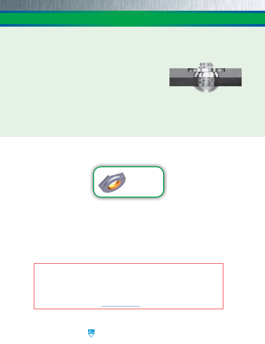
PEMSERT® SELF-CLINCHING FLUSH FASTENERS
F-2
PennEngineering • www.pemnet.com
PEMSERT® self-clinching flush nuts are designed to be installed into sheets as thin as .060”/1.5 mm.
These Types F and F4™ fasteners are ideal for applications where a thin sheet requires threads stronger than a tapped hole
but still must remain flat, with no protrusions on either surface, enhancing the functional and cosmetic qualities of the entire
assembly.
PEMSERT® flush nuts are installed easily by squeezing them into a round hole
in metal sheets. They can be installed before bending and forming to provide
threads in places which would be inaccessible for installation after chassis are
formed. The hexagonal head along with the proven PEM® self-clinching design
ensures high axial and torsional strength.
Type F4™ flush nuts are specifically designed to be installed into stainless steel sheets.
PEMSERT® Type F fasteners can be ordered to conform to US NASM45938/4 specifications.*
*To meet national aerospace standards and to obtain testing documentation, product must be ordered to NASM45938/4 specifications.
Consult our Marketing department for a complete Military Specification and National Aerospace Standards Reference Guide (Bulletin
NASM) or check our web site.
Fastener drawings
and models are
available at
www.pemnet.com
A NOTE ABOUT FASTENERS FOR STAINLESS STEEL PANELS
In order for self-clinching fasteners to work properly, the fastener must be harder than the sheet into which it is being installed. In
the case of stainless steel panels, fasteners made from 300 Series Stainless Steel do not meet this hardness criteria. It is for this
reason that 400 series fasteners are offered (Type F4). However, while these 400 Series fasteners install and perform well in 300
Series stainless sheets they should not be used if the end product:
•
Will be exposed to any appreciable corrosive environment.
•
Requires non-magnetic fasteners.
•
Will be exposed to any temperatures above 300
°
F (149
°
C)
If any of the these are issues, please contact
techsupport@pemnet.com
for other options.
pem-html.html
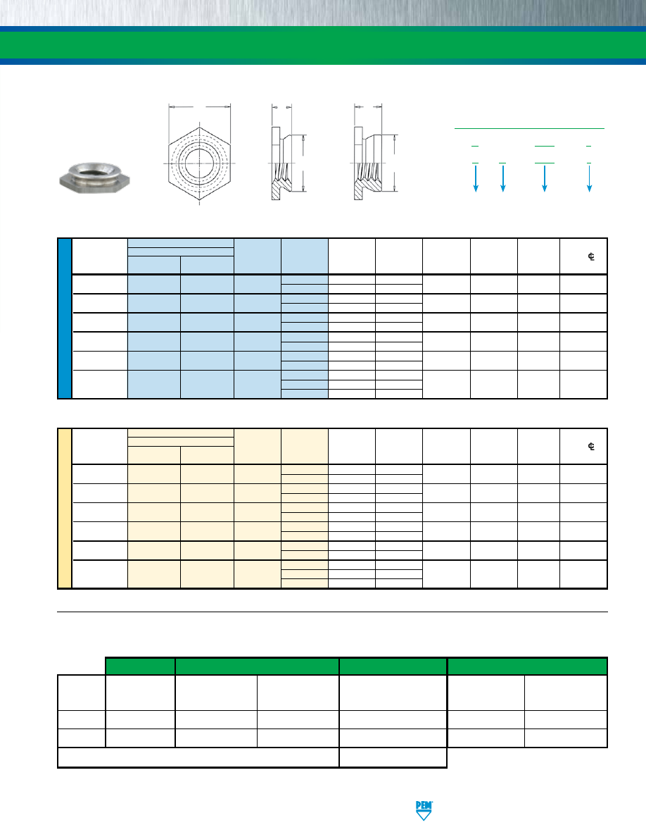
PEMSERT® SELF-CLINCHING FLUSH FASTENERS
All dimensions are in inches.
All dimensions are in millimeters.
PennEngineering • www.pemnet.com
F-3
U
NIF
IE
D
Type
A
Hole Size
Min. Dist.
Thread
Fastener Material
Thread
Shank
(Shank) Sheet In Sheet C H Hole
CL
Size
Code
Code
Max. Thickness
+.003 -.000 Max. Nom. To Edge
.086-56
F F4 256
1
.060
.060 - .091
.172 .171 .188 .23
(#2-56)
2
.090
.091 Min.
.112-40
F F4 440
1
.060
.060 - .091
.172 .171 .188 .23
(#4-40)
2
.090
.091 Min.
.138-32
F F4 632
1
.060
.060 - .091
.213 .212 .250 .27
(#6-32)
2
.090
.091 Min.
.164-32
F F4 832
1
.060
.060 - .091
.290 .289 .312 .28
(#8-32)
2
.090
.091 Min.
.190-32
F F4 032
1
.060
.060 - .091
.312 .311 .343 .31
(#10-32)
2
.090
.091 Min.
.250-20
3
.120
.125 - .156
(1/4-20)
F
F4
0420
4
.151
.156 - .187
.344
.343
.375
.34
5
.182
.187 Min.
Stainless
Steel
Heat-Treated
Stainless Steel
ME
TR
IC
Type
A
Hole Size
Min. Dist.
Thread
Fastener Material
Thread
Shank
(Shank) Sheet In Sheet C H Hole
CL
Size
Code
Code
Max. Thickness +0.08 Max. Nom. To Edge
M2 x 0.4
F
F4
M2
1
1.53
1.53 - 2.32
4.37 4.35 4.8 6
2
2.3
2.32 Min.
M2.5 x 0.45
F
F4
M2.5
1
1.53
1.53 - 2.32
4.37 4.35 4.8 6
2
2.3
2.32 Min.
M3 x 0.5
F
F4
M3
1
1.53
1.53 - 2.32
4.37 4.35 4.8 6
2
2.3
2.32 Min.
M4 x 0.7
F
F4
M4
1
1.53
1.53 - 2.32
7.37 7.35 7.9 7.2
2
2.3
2.32 Min.
M5 x 0.8
F
F4
M5
1
1.53
1.53 - 2.32
7.92 7.9 8.7 8
2
2.3
2.32 Min.
3
3.05
3.18 - 3.96
M6 x 1
F
F4
M6
4
3.84
3.96 - 4.75
8.74
8.72
9.5
8.8
5
4.63
4.75 Min.
300 Series
Stainless Steel
Heat-Treated
Stainless Steel
Profile for
-1 shank code.
Clinching profile may vary.
Profile for -2, -3, -4,
& -5 shank codes.
H
C
A
C
A
Threads
Fastener Materials
Standard Finish
For Use in Sheet Hardness: (1)
Internal,
Heat-Treated
Passivated and/or
HRB 88 /
HRB 70 /
ASME B1.1, 2B /
300 Series
400 Series
Tested Per
HB 183
HB 125
Type
ASME B1.13M, 6H
Stainless Steel
Stainless Steel
ASTM A380
or less
or less
F
•
•
•
•
F4
•
• • •
Part Number Code For Finishes
None
(1) HRB - Hardness Rockwell “B” Scale. HB - Hardness Brinell.
MATERIAL AND FINISH SPECIFICATIONS
F
4 – 632 – 1
Type
PART NUMBER DESIGNATION
Material
Code
Thread Size
Code
Shank
Code
F – 632 – 1
pem-html.html
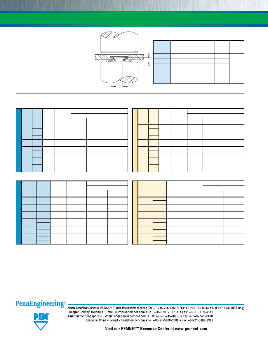
INSTALLATION
1.
Prepare properly sized round mounting hole in
sheet. Do not perform any secondary operations
such as deburring.
2.
Place fastener onto the anvil and place the
mounting hole over the shank of the fastener as
shown in the drawing.
3.
With installation punch and anvil surfaces
parallel, apply sufficient squeezing force only to
embed hexagonal head flush in sheet. The metal
displaced by the head flows evenly and smoothly
around the back-tapered shank of the fastener,
securely locking it into place with high pullout
resistance while at the same time, the embedded
hexagonal head provides high torque resistance.
PEMSERT® SELF-CLINCHING FLUSH FASTENERS
PERFORMANCE DATA
(1)
F-4
ME
TR
IC
Axial
Rec.
Test Sheet Material
Thread Shank Tensile Tightening 5052-H34 Aluminum Cold-rolled Steel
Code Code Strength Torque
(3)
(kN)
(2)
(N•m)
Installation Pushout Installation Pushout
(kN) (N) (kN) (N)
M2
1
0.57 0.16 8.9 665 13.3 890
2
M2.5
1
0.68 0.23 8.9 665 13.3 890
2
M3
1
0.85 0.36 8.9 665 13.3 890
2
M4
1
1 0.58 8.9 1068 17.8 1068
2
M5
1
1.3 0.88 11.1 1068 22.2 1068
2
3
M6 4 4.5 3.7
15.6 2847 26.7 3736
5
Anvil Dimensions
Anvil
Punch
Thread
A
P
Part
Part
Code +.002 -.000”/+0.05mm ±.005”/0.13mm Number Number
256/M2/M2.5
.060” / 1.52mm
.050” / 1.27mm 8006193
440/M3
.077” / 1.96mm
.050” / 1.27mm 975200040
632
.092” / 2.34mm
.050” / 1.27mm 975200041 975200048
832/M4
.124” / 3.15mm
.050” / 1.27mm 975200042
032/M5
.139” / 3.53mm
.050” / 1.27mm 975200043
0420/M6
.186” / 4.72mm
.100” / 2.54mm 975200044
PEMSERTER® Installation Tooling
(1) Published installation forces are for general reference. Actual set-up and confirmation of complete installation should be made by observing proper
seating of fastener as described in the installation steps. Other performance values reported are averages when all proper installation parameters and
procedures are followed. Variations in mounting hole size, sheet material, and installation procedure may affect performance. Performance testing
this product in your application is recommended. We will be happy to provide technical assistance and/or samples for this purpose.
(2) Failure occurs in screw stripping using a 60 ksi screw and the shortest shank length fastener.
(3) Torque values shown will produce a preload of 70% of axial tensile strength with nut factor “k” equal to .2. Threads may strip or head of the F nut may bend and/
or fail if screw is over-torqued beyond these values or if actual k value is less than .2.
U
NIF
IE
D
Axial
Rec. Test Sheet Material
Thread Shank
Tensile
Tightening 300 Series Stainless Steel
Code Code
Strength Torque
(3)
(lbs.)
(2)
(in. lbs.)
Installation
Pushout
(lbs.) (lbs.)
256
1
130 1.50 7200 270
2
440
1
165 2.50 7200 270
2
632
1
190 3.50 7200 290
2
832
1
230 5.25 9000 450
2
032
1
280 7.50 9000 450
2
3
0420
4 1035 36
14000 1000
5
ME
TR
IC
Axial
Rec. Test Sheet Material
Thread Shank
Tensile
Tightening 300 Series Stainless Steel
Code Code
Strength Torque
(3)
(kN)
(2)
(N•m)
Installation
Pushout
(kN) (N)
M2
1
0.57 0.16 32 1200
2
M2.5
1
0.68 0.23 32 1200
2
M3
1
0.85 0.36 32 1200
2
M4
1
1 0.58 40 2000
2
M5
1
1.3 0.88 40 2000
2
3
M6
4 4.5 3.7
65 4500
5
Type F
Type F4
U
NIF
IE
D
Axial
Rec.
Test Sheet Material
Thread Shank Tensile Tightening 5052-H34 Aluminum Cold-rolled Steel
Code Code Strength Torque
(3)
(lbs.)
(2)
(in. lbs.)
Installation Pushout Installation Pushout
(lbs.) (lbs.) (lbs.) (lbs.)
256
1
130 1.50 2000 150 3000 200
2
440
1
165 2.50 2000 150 3000 200
2
632
1
190 3.50 2000 200 3600 200
2
832
1
230 5.25 2000 240 4000 240
2
032
1
280 7.50 2500 240 5000 240
2
3
0420 4 1035 36
3500 640 6000 840
5
Technical support e-mail: techsupport@pemnet.com
All PEM® products meet our stringent quality standards. If you require additional industry or other specific quality certifications, special procedures and/or part
numbers are required. Please contact your local sales office or representative for further information.
Regulatory compliance information is available in Technical Support section of our website. Specifications subject to change without notice. See our website for the
most current version of this bulletin.
© 2016 PennEngineering.
PUNCH
ANVIL
P
A
pem-html.html
MINIATURE SELF-CLINCHING
FASTENERS
FE
™
317
BULLETIN
pem-html.html
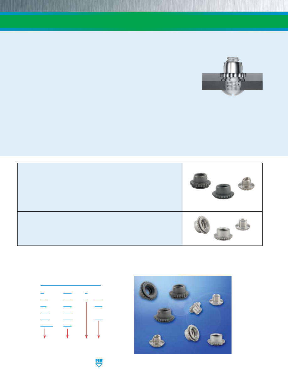
MINIATURE SELF-CLINCHING FASTENERS
FE-2
PennEngineering • www.pemnet.com
U –
080 – 0
UL –
080 – 0 CW
FE –
440 – MD
FEX – 440
FEO – 440 – MD
FEOX – 440
Finish
Code
PART NUMBER DESIGNATION
Type
Thread
Code
Shank
Code
PEM® brand miniature fasteners fit into a minimal space and provide strong, reusable threads.
PEM miniature fasteners provide immediate visual indication when proper installation has been accomplished.
A strong, knurled collar, which is embedded in the sheet, guarantees against rotation of
the fastener in the sheet. The torque-out resistance of the knurl greatly exceeds the torque
that can be exerted by the self-locking feature.
When this collar is embedded in the sheet, the undercut cavity beneath the collar is filled
with displaced sheet material thereby developing pushout resistance.
FE/FEO/UL prevailing torque locknuts provide ideal solutions to prevent mating hardware from loosening in service due to
vibration or other application-related factors. A design feature of the lock nut produces friction between threads of mated
components thereby increasing the force needed to tighten as well as loosen the nut. Prevailing torque locknuts provide
essentially the same torque value regardless of the amount of axial load applied. Their use can save time and money
compared with alternative chemical locking methods or patches.
A dry-film lubricant applied to locking FE/FEO/UL nuts provides the smooth, non-galling prevailing torque performance
necessary for reliable locking and for reusability.
(1)
Screws for use with PEM self-clinching locking fasteners should be Class
3A/4h fit or no smaller than Class 2A/6g.
FE™/FEO™/UL™
elliptically squeezed nuts are
self-locking
. FE/FEO nut
thread locking torque performance is equivalent to applicable NASM25027
specifications. UL self-locking nuts meet locking torque requirements
specified herein. Some sizes of FE/FEO/UL nuts can be ordered to
NASM45938/7 specifications
(2)
. For more information on NASM25027 as
applied to PEM self-clinching, self-locking nuts, check our web site for tech
sheet PEM® - Ref/NASM25027.
FEX™/FEOX™/U™
nuts have
free-running
class 2B/6H strong reusable
threads. These fasteners can be installed into thinner sheets and closer to
the edge of a sheet than standard self-clinching nuts. Some sizes of FEX/
FEOX/U nuts can be ordered to NASM45938/7 specifications
(2)
.
(1) Consult Bulletin LN for complete line of self-clinching, locking fasteners.
(2) To meet national aerospace standards and to obtain testing documentation, product must be ordered using appropriate NASM45938/7
part number. Check our web site for a complete Military Specification and National Aerospace Standards Reference Guide (Bulletin
NASM).
pem-html.html
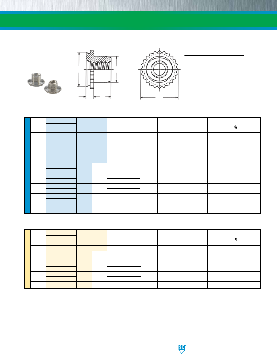
ME
TR
IC
U
NIF
IE
D
All dimensions are in inches.
Type
Hole Size
Min.
Max. Hole
Shank
A
Sheet
In
Sheet
C T Dist. In
Thread Non- Self- Thread Code (Shank) Thickness +.003 +.000
D
E
+.015 Hole
C/L
Attached
Size locking
(1)
locking Code
(2)
Max.
(3)
–.000
–.005
Max.
±.005
–.000
To Edge
Parts
.060-80
U UL 080 0 .020 .019-.022 .110 .1095 .076 .125 .050 .09
.080
(#0-80)
.073-64
U UL 164 0 .020
.019-.022
.110 .1095 .090 .125 .050 .09 .093
(#1-64)
.086-56
U UL 256
0 .020 .019-.022
.144 .1435 .106 .160 .065
.11 .106
(#2-56)
1
.031
.030-.036
.112-40 FEOX FEO
440
.040 .039-.045
.172 .171 .145 .192 .065
.14 .132
(#4-40)
FEX
FE
.060
.059-.070
.138-32 FEOX FEO
632
.040 .039-.045
.213 .212 .180 .244 .075
.17 .158
(#6-32)
FEX
FE
.060
.059-.070
.164-32 FEOX FEO
832
.040 .039-.045
.290 .289 .215 .322 .090
.20 .184
(#8-32)
FEX
FE
.060
.059-.070
.190-32 FEOX FEO
032
.040 .039-.045
.290 .289 .245 .322 .110
.20 .210
(#10-32)
FEX
FE
.060
.059-.070
1/4-20
FEX FE
0420
.060 .059-.070 .344 .343 .318 .384 .120
.28 .270
1/4-28
0428
All dimensions are in millimeters.
Type
Min.
Max. Hole
Thread
Shank
A
Sheet
Hole
Size
Dist. In
Size x
Non-
Self-
Thread
Code
(Shank)
Thickness
In Sheet
C
D
E
T
Hole
C/L
Attached
Pitch locking
(4)
locking Code
(2)
Max.
(3)
+0.08
–0.13
Max.
±0.13
+0.4
To Edge
Parts
M2
x 0.4
U
UL
M2
1
0.79
0.76-0.91
3.61
3.6
2.5
4.07
1.65
2.8
2.5
M3 x 0.5
FEOX FEO
M3
1.02 0.99-1.14
4.39 4.37 3.96 4.88 1.9
3.6 3.5
FEX
FE
1.53
1.5-1.78
M4 x 0.7
FEOX FEO
M4
1.02 0.99-1.14
7.39 7.37 5.23 8.17 2.55
5.2 4.5
FEX
FE
1.53
1.5-1.78
M5 x 0.8
FEOX FEO
M5
1.02 0.99-1.14
7.39 7.37 6.48 8.17 3.05
5.2 5.5
FEX
FE
1.53
1.5-1.78
M6
x 1
FEX
FE
M6
1.53
1.5-1.78
8.74
8.72
7.72
9.74
3.3
7.1
6.5
(1) 2B Go Gauge may stop at barrel end but class 3A screw will pass thru with finger torque.
(2) Shank code applicable only to U and UL fasteners.
(3) In applications between the sheet thicknesses for your thread size, see last paragraph of installation data on page 4. Knurled collar may fracture if
fastener is used in sheets thicker than the specified range and the screw is tightened beyond maximum tightening torque.
(4) 6H Go Gauge may stop at barrel end but class 4h screw will pass thru with finger torque.
U/FEX/FEOX NUTS ARE ROUND
TOPS OF UL/FE/FEO NUTS
HAVE ELLIPTICALLY SQUEEZED
LOCKING FEATURE
MINIATURE SELF-CLINCHING FASTENERS
PennEngineering • www.pemnet.com
FE-3
SPECIFICATIONS
C
D
E
A
T
Clinching profile may vary.
pem-html.html
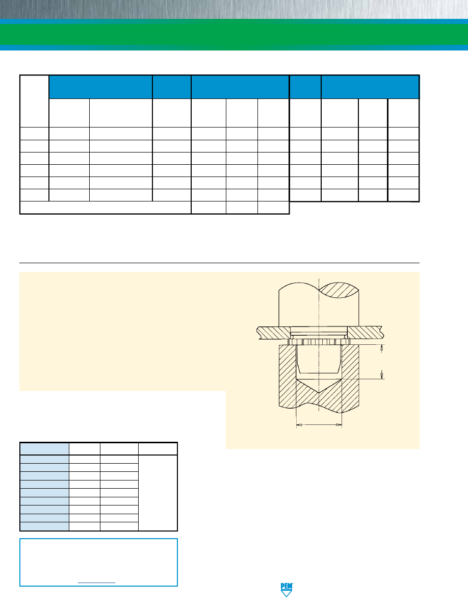
MINIATURE SELF-CLINCHING FASTENERS
Fastener
For Use
Threads
Material
Standard Finishes
In Sheet
Hardness
(1)
Internal, UNJ Class 3B per
Passivated
Passivated
Type
Internal,
ASME B1.15 / MJ Class 4H6H
and/or
Plus Clear
Black
HRB 70 /
Locking
ASME B1.1, 2B /
per ASME B1.21M
300 Series
Tested Per
Dry-film
Dry-film
HB 125
Temperature
Covered by
ASME B1.13M, 6H
(M6 thread 4H5H)
Stainless Steel
ASTM A380
Lubricant
Lubricant
or Less
Limit
Self-locking M45938/7
(2)
U
•
• • •
UL
•
• • •
400˚ F / 204˚ C
• •
FE
•
• • •
400˚ F / 204˚ C
• •
FEX
•
• • •
FEO
•
• • •
400˚ F / 204˚ C
• •
FEOX
•
• • •
Part number codes for finishes
None
CW
(3)
MD
(4)
(1) HRB - Hardness Rockwell “B” Scale. HB - Hardness Brinell.
(2) To meet national aerospace standards and to obtain testing documentation, product must be ordered using appropriate NASM45938 part number.
Check our web site for a complete Military Specification and National Aerospace Standards Reference Guide (Bulletin NASM).
(3) See PEM Technical Support section of our web site for related plating standards and specifications.
(4) MD finish on stainless steel provides a minimum of 100 hours of salt spray resistance.
MATERIAL AND FINISH SPECIFICATIONS
PEM miniature fasteners must be installed by a force applied through parallel
surfaces. Since force must not be applied to the barrel, a cavity must be used in
either the punch or anvil so that the installation force is applied to the knurled collar.
“D” dimensions for the punch or anvil cavity are given in the tables on page 3.
INSTALLATION
1.
Prepare properly sized mounting hole in sheet. Do not perform
any secondary operations such as deburring.
2.
Insert fastener into the anvil hole and place the mounting hole
(preferably the punch side) over the shank of the fastener as
shown in the drawing.
3.
With installation punch and anvil surfaces parallel, apply
squeezing force to the knurled collar until knurled collar is flush
with top of the sheet for sheets .060”/1.5mm thick and up, or
until shank is flush with the bottom of the sheet for sheets
.040”/1mm to .060”/1.5mm thick for FE/FEO nuts.
PEMSERTER® Installation Tooling
INSTALLATION RECOMMENDATION
In applications for sheet thicknesses between the two ranges (see “Sheet
Thickness” on page 3) use the fastener with the larger “A” dimension. For
example, if you want a #4-40 thread and your sheet thickness is between
.045”/1.14 mm and .059”/1.49 mm, you should use FE or FEX nuts. This is
not recommended installation practice, but in this case if it is necessary, you
should install the fastener so that the bottom of the shank is flush with the
underside of the sheet (instead of having the top of the knurled collar flush
with the top of the sheet). When this method is used, care must be taken to
protect the fastener against crushing which would damage the threads. This
method will also result in reduced pushout and torque-out values.
Anvil Part
Punch Part
Type Thread
Number Number
U/UL
080 8008451
U/UL
164 970200300300
U/UL
256/M2 975200020
FE/FEO/FEX/FEOX 440/M3
975200021
FE/FEO/FEX/FEOX
632
975200022
975200048
FE/FEO/FEX/FEOX 832/M4
975200023
FE/FEO/FEX/FEOX 032/M5
975200024
FE/FEO/FEX/FEOX
0420
975200025
FE/FEO/FEX/FEOX
M6
8013143
PUNCH
T*
+.010” / +0.25 mm
Min.
D* +.005” / +0.13 mm
+.010” / +0.25 mm
ANVIL
*
For “D” and “T”,
see page 3.
INSTALLATION NOTES
•
For best results we recommend using a PEMSERTER®
press for installation of PEM self-clinching fasteners. Please
check our website for more information.
•
Visit the Animation Library on our website to view the
installation process
for this product
.
PennEngineering • www.pemnet.com
FE-4
pem-html.html
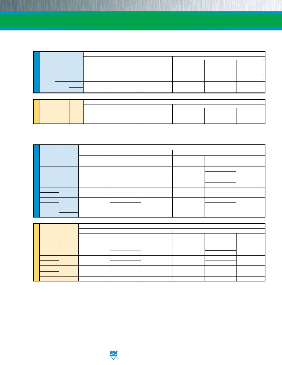
PERFORMANCE DATA
(1)
MINIATURE SELF-CLINCHING FASTENERS
(1) Published installation forces are for general reference. Actual set-up and confirmation of complete installation should be made by
observing proper seating of fastener as described in the installation steps. Other performance values reported are averages when all
proper installation parameters and procedures are followed. Variations in mounting hole size, sheet material, and installation procedure
may affect performance. Performance testing this product in your application is recommended. We will be happy to provide technical
assistance and/or samples for this purpose.
(2) For FE and FEO fasteners, thread locking performance is equivalent to applicable NASM25027 specifications. Consult technical sheet PEM-REF/
NASM25027 on our web site for details.
PERFORMANCE DATA FOR TYPES U/UL
(1)
ME
TR
IC
U
NIF
IE
D
Test Sheet Material
5052-H34 Aluminum
Cold-rolled Steel
Type Thread Shank Installation
Pushout
Torque-out
Installation
Pushout
Torque-out
Code Code
(lbs.)
(lbs.)
(in. lbs.)
(lbs.)
(lbs.)
(in. lbs.)
080 0
750
20
2
1000
30
2
U/UL
164
0
750
20
3
1000
30
3
256
0
1000 20
4
1300 30 4
1
Test Sheet Material
5052-H34 Aluminum
Cold-rolled Steel
Type Thread
Shank
Installation Pushout Torque-out Installation Pushout Torque-out
Code Code (kN)
(N)
(N•m)
(kN)
(N)
(N•m)
U/UL M2 1
4
89
0.45
5.8
133
0.45
ME
TR
IC
U
NIF
IE
D
Test Sheet Material
5052-H34 Aluminum
Cold-rolled Steel
Thread
Type
Code
Installation
Pushout
Torque-out
Installation
Pushout
Torque-out
(lbs.)
(lbs.)
(in. lbs.)
(lbs.)
(lbs.)
(in. lbs.)
FEO/FEOX
440
900
88
12 1500
140
12
FE/FEX
135 210
FEO/FEOX
632
1200
105
20 2100
185
20
FE/FEX
1300
175
255
FEO/FEOX
832
1500
155
48 2500
260
48
FE/FEX
255 360
FEO/FEOX
032
1500
155
48 2500
260
48
FE/FEX
255 360
FE/FEX
0420
2100
320
110
3500
420
110
0428
Test Sheet Material
5052-H34 Aluminum
Cold-rolled Steel
Thread
Type
Code
Installation
Pushout
Torque-out
Installation
Pushout
Torque-out
(kN)
(N)
(N•m)
(kN)
(N)
(N•m)
FEO/FEOX
M3
4
391
1.35
6.7
622
1.35
FE/FEX
600
934
FEO/FEOX
M4
6.7
689
5.42 11.1
1156
5.42
FE/FEX
1134
1601
FEO/FEOX
M5
6.7
689
5.42 11.1
1156
5.42
FE/FEX
1134
1601
FE/FEX
M6
9.4
1423
12.43
15.6
1868
12.43
PERFORMANCE DATA FOR TYPES FE/FEO/FEX/FEOX
(1)(2)
FE-5
PennEngineering • www.pemnet.com
pem-html.html
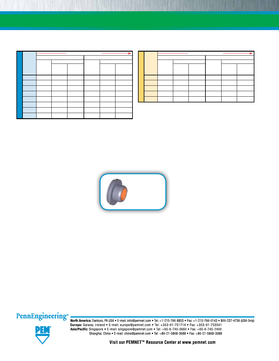
FE-6
MINIATURE SELF-CLINCHING FASTENERS
Fastener drawings
and models are
available at
www.pemnet.com
AXIAL STRENGTH AND TIGHTENING TORQUE COMPARISON
U
NIF
IE
D
U-0/UL-0/FEOX/FEO Nuts
U-1/UL-1/FEX/FE Nuts
Thread
Locknut Mating Screw
Locknut Mating Screw
Code Min. Axial
Strength
Tightening
Min. Axial
Strength
Tightening
Strength Level Torque Strength Level Torque
(lbs.)
(1)
(ksi)
(2)
(in. lbs.)
(3)
(lbs.)
(1)
(ksi)
(2)
(in. lbs.)
(3)
080
125
69
1.0
—
—
—
164
125
49
1.2
—
—
—
256
169
46
1.9
316
85
3.5
440
465
77
6.8
705
117
10.3
632
546
60
9.8
847
93
15.2
832
779
56
16.6
1,213
87
25.9
032
779
39
19.2
1,213
61
30.0
0420
—
—
—
1,412
44
45.9
(1) Axial strength for nuts is limited by knurled ring strength.
(2) Screw strength level shown is the minimum needed to develop full nut strength, higher strength screws may be used.
(3) Tightening torque shown will induce preload of 65% of locknut minimum axial strength with K or nut factor is equal to 0.20. In some applications
tightening torque may need to be adjusted based on the actual K value. If screw strength is less than the value shown, tightening torque should be
proportionately reduced by multiplying the torque shown by the actual screw strength over the screw strength shown. If higher strength screws are
used, torque is not adjusted upward because assemble strength is still limited by locknut strength.
ME
TR
IC
U-0/UL-0/FEOX/FEO Nuts
U-1/UL-1/FEX/FE Nuts
Thread
Locknut Mating Screw
Locknut Mating Screw
Code Min. Axial
Strength
Tightening
Min. Axial
Strength
Tightening
Strength Level Torque Strength Level Torque
(kN)
(1)
(MPa)
(2)
(N•m)
(3)
(kN)
(1)
(MPa)
(2)
(N•m)
(3)
M2
—
—
—
1.39
432
0.36
M3
2.08
267
0.81
3.16
405
1.23
M4
3.48
255
1.81
5.42
398
2.82
M5
3.48
158
2.26
5.42
246
3.52
M6 — — — 6.28 201 4.9
Increasing Axial Strength
Increasing Axial Strength
Technical support e-mail: techsupport@pemnet.com
All PEM® products meet our stringent quality standards. If you require additional industry or other specific quality certifications, special procedures and/or part
numbers are required. Please contact your local sales office or representative for further information.
Regulatory compliance information is available in Technical Support section of our website. Specifications subject to change without notice. See our website for the
most current version of this bulletin.
© 2017 PennEngineering.
pem-html.html
FH
™
SELF-CLINCHING
STUDS AND PINS
PEM® brand self-clinching studs and
pins install permanently in aluminum,
steel or stainless steel sheets.
Bulletin FH-1217
Rev 218
pem-html.html
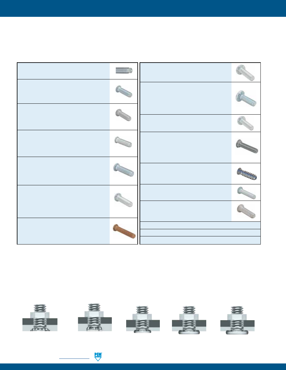
FH-2
PennEngineering •
www.pemnet.com
SELF-CLINCHING STUDS AND PINS
PEM® self-clinching studs are easily installed by placing them in properly sized holes in sheets and squeezing into
place with any standard press:
•
Install permanently in aluminum, steel or stainless steel in sheets as thin as .020” / 0.51 mm.
•
High torque-out and pushout resistances.
Flush-head studs
Types FH/FHA/FHS/FHP/FH4
PAGE 5
Flush, low-displacement head studs
Types FHL/FHLS
PAGE 7
Thin sheet studs
Types TFH/TFHS
PAGE 8
Heavy-duty studs
Types HFH/HFHS/HFHB
PAGE 9
Heavy-duty studs for thin sheets
Types HFE/THFE
PAGE 10
HFE™/THFE™ (heavy-duty) studs
Provides
maximum pull through in sheets as thin as
.031” / 0.8 mm -
PAGE 10
HFG8™/HF109™ (heavy-duty high tensile
strength) studs
are manufactured for the
most demanding applications from medium
carbon alloy steel, then heat-treated to high
strength and hardness qualities -
PAGE 11
HFLH™ studs
are for installation into thin,
harder, high-strength materials -
PAGE 12
SGPC™ swaging collar studs
can install
into most panel material and accommodate
multiple panels as long as the total thickness
does not exceed the maximum sheet
thickness -
PAGE 13
FHX™ flush-head studs with X-Press™ thread
profile
are typically used with push-on or
other plastic fasteners -
PAGE 14
FH™/FHS™/FHA™ (flush-head) Pins
are
available on special order -
PAGE 15
TPS™/TP4™/TPXS™ (flush-head) pilot pins
satisfy a wide range of positioning, pivot, and
alignment applications -
PAGE 16
Material and finish specifications -
PAGE 17
Installation -
PAGES 18 - 25
Performance data -
PAGES 26 - 32
Dog Point and Anti Cross-Thread Options -
PAGE 4
FH™/FHS™/FHA™ (flush-head) studs
are
available in aluminum, steel, or stainless
steel -
PAGE 5
FH4™/FHP™ (flush-head) studs
are designed
to provide strong threads in stainless steel
sheets as thin as .040”/1 mm. FHP studs have
high corrosion resistance -
PAGE 6
FHL™/FHLS™ (flush, low-displacement head)
studs
have a smaller head diameter and install
closer to the edge of a sheet than PEM FH/FHS
studs -
PAGE 7
TFH™/TFHS™ (non-flush) studs
are for
sheets as thin as .020” / 0.51 mm. The stud
head will project above the sheet surface
approximately .025”/0.64mm -
PAGE 8
HFH™/HFHS™ (heavy-duty) studs
have a
large head which projects above the sheet
material to distribute the axial tightening
force over a large area thereby improving pull
through resistance -
PAGE 9
HFHB™ (heavy-duty BUSBAR®) studs
are
ideal for applications which demand superior
electrical/mechanical attachment points -
PAGE 9
© 2017 PennEngineering.
pem-html.html
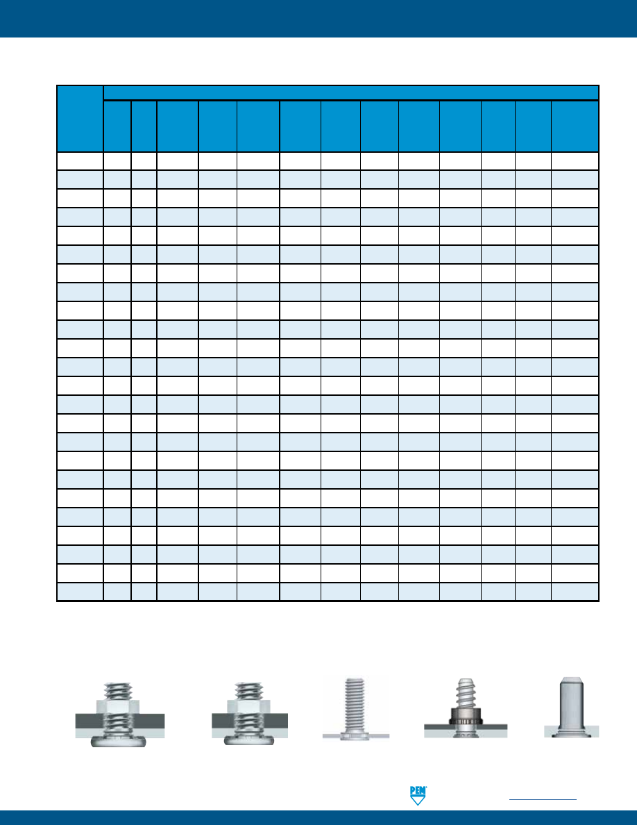
PennEngineering •
www.pemnet.com
FH-3
SELF-CLINCHING STUDS AND PINS
A p p l i c a t i o n R e q u i r e s :
PEM
Stud
Type
(1) Meets grade 5 / property class 9.8 tensile requirements.
(2) HRB - Hardness Rockwell “B” Scale. HB - Hardness Brinell.
Standard product features shown above. Studs can also be custom designed to meet your exact application requirements.
FH
•
FHA
•
• •
FHS
•
•
FH4
•
•
FHP
•
• •
FHL
•
•
FHLS
•
• •
TFH
•
TFHS
• •
HFH
•
(1)
•
HFHB
•
• • •
HFHS
•
• •
HFE
•
•
THFE
•
•
HFG8/HF109
•
• •
HFLH
•
•
SGPC
• •
FHX
•
•
FH
•
•
FHA
•
• • •
FHS
•
• •
TPS
•
• •
TP4
•
• •
TPXS
•
• •
STUD SELECTOR GUIDE
Heavy-duty, high tensile strength studs
Types HFG8/HF109
PAGE 11
Flush-head pins
Types TPS/TP4
PAGE 16
PAGE 13
Swaging collar studs
Type SGPC
Studs for hard panels
Type HFLH
PAGE 12
Grade 8/
Sheet
Installation Compati-
Property thickness
into
bility
Closest
Large Max.
Class 10.9
as thin as
Superior
stainless
with
Superior
centerline-
hole in
Push on
panel
Flush- Heavy
thread
.020” /
electrical
steel
aluminum
corrosion
to-edge
Unthreaded attached
plastic
hardness
head
duty
strength
0.51 mm conductivity
sheets
anodizing resistance
distance
stud/pin
Panel
fasteners
(2)
Unthreaded
Unthreaded
Unthreaded
PAGE 14
Flush-head Studs with
X-Press™ Thread Profile
Type FHX
HRB 80
HB 150
HRB 50
HB 82
HRB 70
HB 158
HRB 92
HB 195
HRB 92
HB 195
HRB 80
HB 150
HRB 70
HB 125
HRB 80
HB 150
HRB 70
HB 125
HRB 85
HB 165
HRB 55
HB 83
HRB 70
HB 125
HRB 85
HB 165
HRB 85
HB 165
HRB 89
HB 180
HRB 96
HB 216
Any sheet
hardness
HRB 80
HB 150
HRB 80
HB 150
HRB 50
HB 82
HRB 70
HB 125
HRB 70
HB 125
HRB 92
HB 195
HRB 70
HB 125
pem-html.html
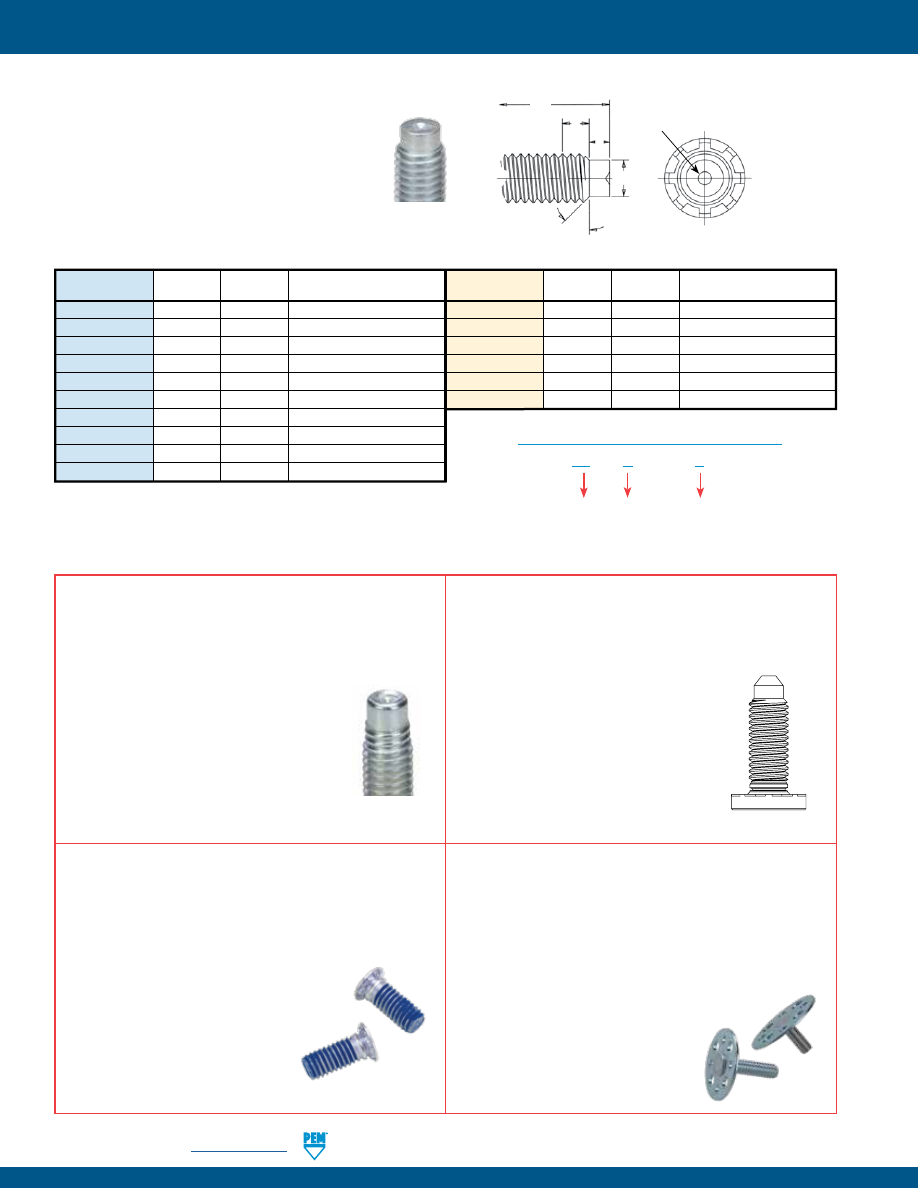
FH-4
PennEngineering •
www.pemnet.com
SELF-CLINCHING STUDS AND PINS
PEM® dog point lead-in option for studs allows quick
location of the mating fastener during assembly
and protects the first thread of the stud during nut
engagement. This feature is available on Types FH, FHL,
HFH, HFE, HF109, HFG8, TFH and THFE studs.
(1) For “L” refer to type stud lengths.
(2) Maximum dog point diameter is .003” / 0.08 mm less than
minimum minor diameter of 2B or 6H nut threads.
OPTIONAL DOG POINT FEATURE
OPTIONAL THREAD MASK
PEM® Blu-Coat™ thread mask is available for applications
where hardware is installed prior to painting. During
assembly, the threads of the mating hardware will remove
paint, electro deposited automotive
under coatings, and weld spatter upon
application of torque. PEM studs can
be specially ordered with thread mask
applied.
“BC” suffix will be added to part number to
designate Blu-Coat thread mask to fastener.
MAThread is a registered trademark of MAThread inc.
C
Approx. 45°
E
B
L
(1)
Standard Dog
Point Detail
Clinching profile may vary.
PEM® Dimple
Registered Trademark
Unified
C ±.005
E ±.010
B Nom.
Metric
C ±0.13
E ±0.25
B nom.
Thread Size
(2)
Transitional Length to Full Thread
Thread Size
(2)
Transitional Length to Full Thread
.138-32 (#6-32)
.086
.050
.098
M3.5 x 0.6
2.4
1.27
1.88
.164-32 (#8-32)
.111
.055
.099
M4 x 0.7
2.79
1.4
2.26
.190-24 (#10-24)
.124
.065
.127
M5 x 0.8
3.66
1.78
2.48
.190-32 (#10-32)
.138
.065
.098
M6 x 1
4.37
2.03
3.05
.250-20 (1/4-20)
.173
.085
.149
M8 x 1.25
6.05
2.67
3.73
.250-28 (1/4-28)
.192
.085
.110
M10 x 1.5
7.72
3.43
4.37
.313-18 (5/16-18)
.228
.105
.164
.313-24 (5/16-24)
.246
.105
.127
.375-16 (3/8-16)
.282
.125
.182
.375-24 (3/8-24)
.309
.125
.126
All dimensions are in inches.
All dimensions are in millimeters.
AVAILABLE PEM® VARIMOUNT®
FASTENING SYSTEM
The PEM® VariMount® fastening system (see PEM® Bulletin
VM) utilizes a self-clinching stud paired with a round steel
or stainless steel base plate to offer a clean and ready-made
assembly for mounting into any rigid material or panel,
including composites, plastics, and
metals. Multiple radial holes in the base
plate and a generous footprint provide
effective mounting of the assembly.
Mounting can be performed either on
the front or through the back of a panel.
Anti Cross-Thread
Feature
FH
D
S
Type:
Any type code
OPTIONAL PART NUMBER DESIGNATION
D = Dog Point
M = MAThread
Material:
Any material code
OPTIONAL POINTED STUD FEATURE
A pointed lead-in option for studs allows quick location of
mating fastener during assembly to speed assembly and
significantly reduces the likelihood of cross
threading. Clip grooves for snap rings can also
be added. This feature can be added to most
types of PEM studs.
OPTIONAL MAThread®
ANTI CROSS-THREAD FEATURE
PennEngineering is a licensee of MAThread® Anti Cross-
Threading Technology. This unique design allows the threads
to self-align and drive easily with reduced effort.
This helps speed assembly, reduce or eliminate
failures, repairs, scrap, downtime, and warranty
service associated with thread damage. This
option is available on most types of PEM studs.
pem-html.html
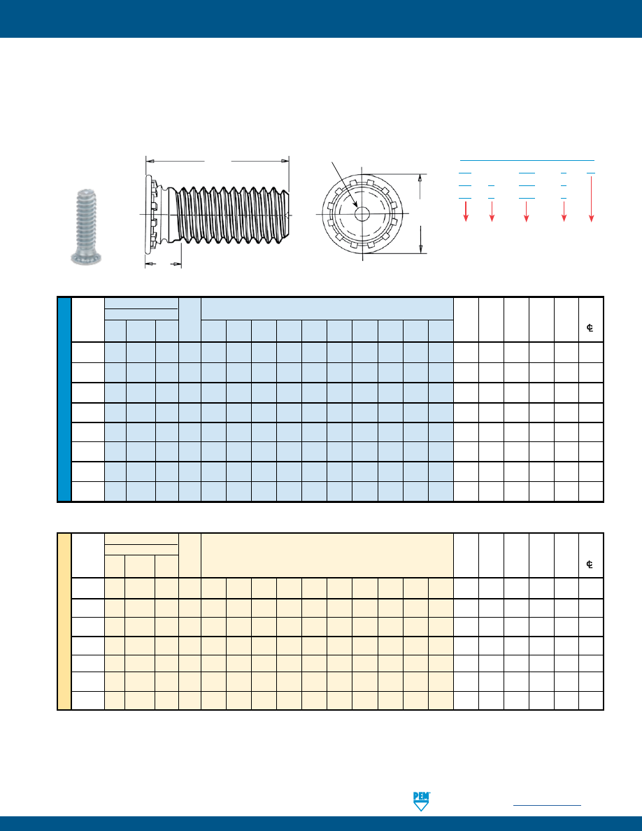
PennEngineering •
www.pemnet.com
FH-5
SELF-CLINCHING STUDS AND PINS
ME
T
RIC
U
NIF
IE
D
Type
Length Code “L” ±.015
Min.
Hole
Max.
Min.
Fastener Material
(Length Code in 16ths of an inch)
Sheet Size in
Hole
Dist.
Thread
Thread
Thick-
Sheet
in H
S
Hole
Size Steel Stainless Alu- Code
.250 .312 .375 .500 .625 .750 .875 1.00 1.25 1.50 ness +.003 Attach.
± .015
Max.
Steel
minum
(1)
-.000
Parts
(2) to Edge
.086-56 FH FHS — 256 4 5 6 8 10 12 — — — — .040 .085 .105 .144 .075 .187
(#2-56)
.112-40 FH FHS FHA 440 4 5 6 8 10 12 14 16 20 — .040 .111 .135 .176 .085 .219
(#4-40)
.138-32 FH FHS FHA 632 4 5 6 8 10 12 14 16 20 24 .040 .137 .160 .206 .090 .250
(#6-32)
.164-32 FH FHS FHA 832 4 5 6 8 10 12 14 16 20 24 .040 .163 .185 .237 .090 .281
(#8-32)
.190-24 FH FHS FHA 024 — 5 6 8 10 12 14 16 20 24 .040 .189 .210 .256 .100 .281
(#10-24)
.190-32 FH FHS FHA 032 — 5 6 8 10 12 14 16 20 24 .040 .189 .210 .256 .100 .281
(#10-32)
.250-20 FH FHS FHA 0420 — — 6 8 10 12 14 16 20 24 .062 .249 .270 .337 .135 .312
(1/4-20)
.313-18 FH FHS — 0518 — — — 8 10 12 14 16 20 24 .093 .311 .333 .376 .160 .375
(5/16-18)
Type
Length Code “L” ±0.4
Min.
Hole Max.
Min.
Thread Fastener Material
(Length Code in millimeters)
Sheet
Size in Hole
Dist.
Size
x
Thread
Thick-
Sheet in
H S
Hole
Pitch Steel Stainless Alu-
Code
ness
+0.08 Attach.
± 0.4
Max.
Steel minum
(1)
Parts
(2) to Edge
M2.5 x 0.45 FH FHS FHA M2.5 6
8
10 12
15 18 — — — — 1 2.5 3.1 4.1 1.95 5.4
M3 x 0.5 FH FHS FHA M3 6
8 10 12 15 18 20 25 — — 1
3 3.6 4.6 2.1 5.6
M3.5 x 0.6 FH FHS FHA M3.5 6
8
10 12
15 18 20 25 30 —
1 3.5 4.1 5.3 2.25 6.4
M4 x 0.7 FH FHS FHA M4 6 8 10 12 15 18 20 25 30 35 1 4 4.6 5.9 2.4 7.2
M5 x 0.8 FH FHS FHA M5 — 8 10 12 15 18 20 25 30 35 1
5 5.6 6.5 2.7 7.2
M6
x 1 FH FHS FHA M6 — — 10 12 15 18 20 25 30 35 1.6 6 6.6 8.2 3 7.9
M8 x 1.25
FH FHS — M8 — — — 12 15 18 20 25 30 35 2.4 8 8.6 9.6 3.7
9.6
All dimensions are in inches.
All dimensions are in millimeters.
(1) See page 18 for installation tool requirements.
(2) Threads are gaugeable to within 2 pitches of the “S” Max. dimension. A class 3B/5H maximum material commercial nut shall pass up to the “S” Max.
dimension.
•
Flush-head for sheet thickness of .040” / 1 mm and greater.
•
FH studs are recommended for use in steel or aluminum sheets HRB (Rockwell “B” scale) 80 / HB (Hardness Brinell) 150 or less.
•
FHS studs are recommended for use in steel or aluminum sheets HRB (Rockwell “B” scale) 70 / HB (Hardness Brinell) 125 or less.
•
FHA studs are recommended for use in aluminum sheets HRB (Rockwell “B” scale) 50 / HB (Hardness Brinell) 82 or less.
L
H
S
unthreaded length
PEM® Dimple
Registered Trademark
FH™/FHS™/FHA™ FLUSH-HEAD STUDS
Type
FH – 632 – 6
ZI
FH
S – 632 – 6
FH
A – 632 – 6
Length
Code
Thread
Code
Finish
Code
Material
Code
PART NUMBER DESIGNATION
Clinching profile may vary.
pem-html.html
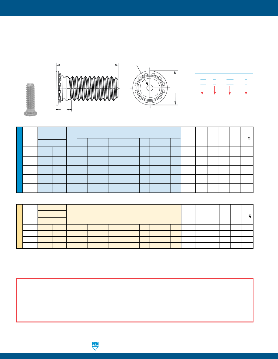
FH-6
PennEngineering •
www.pemnet.com
SELF-CLINCHING STUDS AND PINS
ME
T
RIC
U
NIF
IE
D
(1) See material and finish specifications chart on page 17 for details.
(2) Performance may be reduced for studs installed into thicker sheets.
(3) Threads are gaugeable to within 2 pitches of the “S” Max. dimension. A class 3B/5H maximum material commercial nut shall pass up to the “S” Max.
dimension.
•
Recommended for use in stainless steel sheets HRB (Rockwell “B” Scale) 92 / HB (Hardness Brinell) 195 or less.
•
FHP studs offer optimum corrosion resistance and are ideal for medical, foodservice, and marine applications.
Type
Length Code “L” ±.015 Hole
Max. Min.
Thread
Thread
(Length code in 16ths of an inch)
Sheet
Size
in
Hole
H S
Dist.
Size
Fastener Material
Code
Thick-
Sheet
in
±.015 Max. Hole
C/L
.250 .312 .375 .500 .625 .750 .875 1.00 1.25 1.50 ness +.003 Attach.
to Edge
Stainless Steel
(1)
(2) -.000
Parts (3)
.112-40
FH4 FHP 440 4 5 6 8 10 12 14 16 — — .040-.095
.111 .131 .176
.085 .219
(#4-40)
.138-32
FH4
FHP 632 4 5 6 8 10 12 14 16 20 24 .040-.095 .137 .157 .206 .090 .250
(#6-32)
.164-32
FH4
FHP 832 4 5 6 8 10 12 14 16 20 24 .040-.095 .163 .183 .237 .090 .281
(#8-32)
.190-32
FH4
FHP 032 — 5 6 8 10 12 14 16 20 24 .040-.095 .189 .209 .256 .100 .281
(#10-32)
.250-20
FH4
— 0420 — — 6 8 10 12 14 16 20 24 .062-.117 .249 .269 .337 .135 .312
(1/4-20)
Type
Length Code “L” ±0.4
Hole Max. Min.
Thread
Thread
(Length Code in millimeters)
Sheet
Size in Hole H S
Dist.
Size x Fastener Material
Code
Thick-
Sheet in ±0.4 Max. Hole
C/L
Pitch
ness
+0.08 Attach.
to Edge
Stainless Steel
(1)
(2) parts (3)
M3 x 0.5
FH4
FHP
M3
6
8
10
12
15
18
20
25
—
—
1 - 2.4
3
3.3
4.6
2.1
5.6
M4 x 0.7
FH4
FHP
M4
6
8
10
12
15
18
20
25
30
35
1 - 2.4
4
4.7
5.9
2.4
7.2
M5 x 0.8
FH4
FHP
M5
—
8
10
12
15
18
20
25
30
35
1 - 2.4
5
5.3
6.5
2.7
7.2
M6
x 1
FH4
—
M6
—
—
10
12
15
18
20
25
30
35
1.6 - 3
6
6.8
8.2
3
7.9
All dimensions are in inches.
All dimensions are in millimeters.
FH4™/FHP™ FLUSH-HEAD STUDS FOR STAINLESS STEEL SHEETS
L
H
S
unthreaded length
PEM® Dimple
Registered Trademark
Type
FH
4 – 632 – 6
FH
P – 632 – 6
Length
Code
Thread
Code
Material
Code
PART NUMBER DESIGNATION
Clinching profile may vary.
A NOTE ABOUT 400 SERIES FASTENERS FOR STAINLESS STEEL PANELS
In order for self-clinching fasteners to work properly, the fastener must be harder than the sheet into which it is being installed. In the case of stainless steel panels,
fasteners made from 300 Series Stainless Steel do not meet this hardness criteria. It is for this reason that 400 series fasteners are offered (Types FH4 and TP4).
However, while these 400 Series fasteners install and perform well in 300 Series stainless sheets they should not be used if the end product:
•
Will be exposed to any appreciable corrosive presence.
•
Requires non-magnetic fasteners.
•
Will be exposed to any temperatures above 300˚F (149˚C)
If any of the these are issues, please contact
techsupport@pemnet.com
for other options such as the FHP™ stud, made from precipitation hardened grade stainless
steel which is not subject to these issues.
pem-html.html
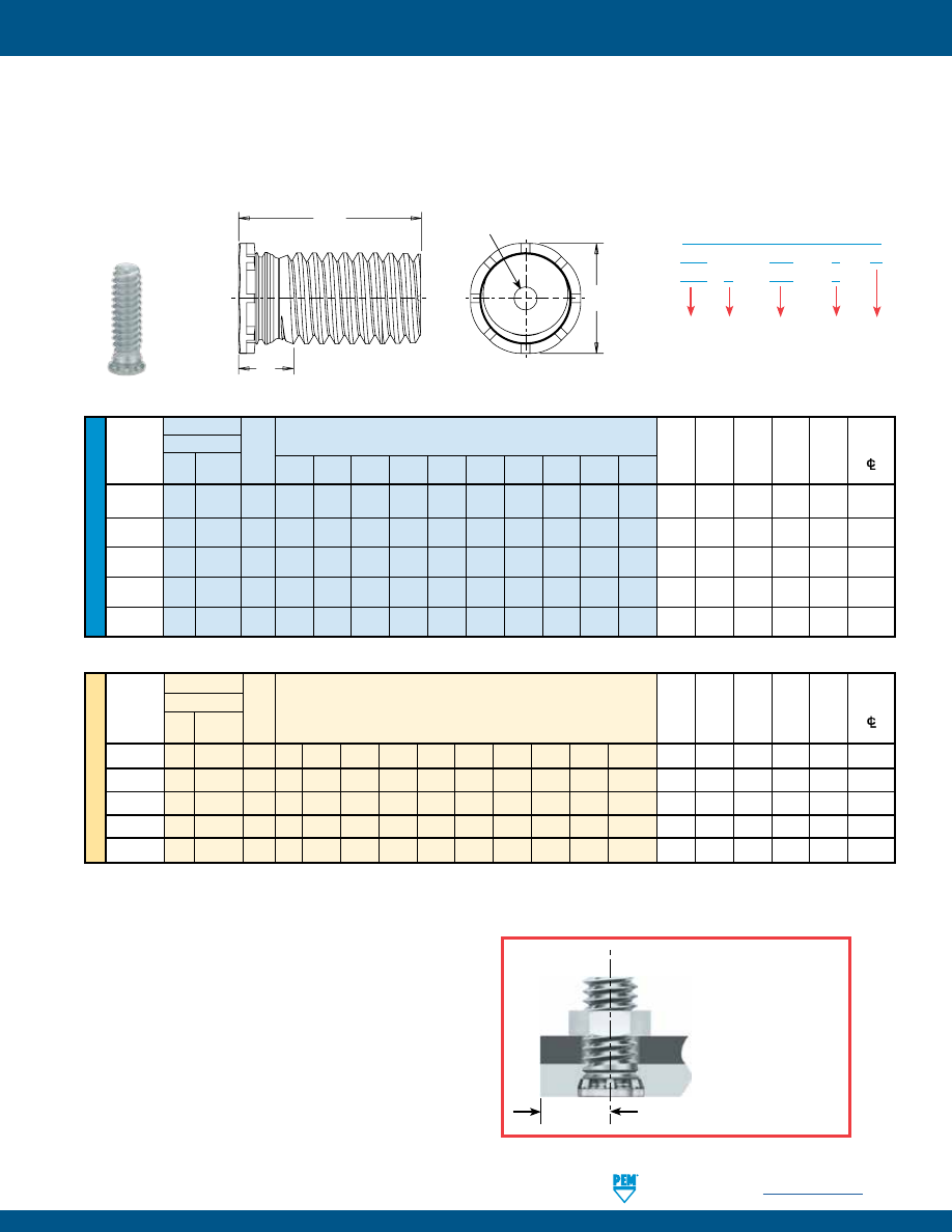
PennEngineering •
www.pemnet.com
FH-7
SELF-CLINCHING STUDS AND PINS
ME
T
RIC
U
NIF
IE
D
•
Installs closer to the edge of a sheet than PEM Type FH/FHS studs without causing that edge to bulge.
•
Flush-head for sheet thickness .040” / 1 mm and greater.
•
FHL studs are recommended for use in steel or aluminum sheets HRB (Rockwell “B” Scale) 80 / HB (Hardness Brinell) 150 or less.
•
FHLS studs are recommended for use in steel or aluminum sheets HRB (Rockwell “B” Scale) 70 / HB (Hardness Brinell) 125 or less.
Type
Min. Hole Max.
Min.
Fastener Material
Sheet Size in
Hole
Dist.
Thread Thread
Thick-
Sheet
in H S Hole
Size Steel
Stainless Code
.250 .312 .375 .500 .625 .750 .875 1.00 1.25 1.50 ness +.003 Attach.
±.015 Max.
Steel
(1)
-.000
Parts
(2)
to Edge
.086-56 FHL FHLS 256 4 5 6 8 10 12 — — — — .040 .085 .100 .112 .080 .098
(#2-56)
.112-40 FHL FHLS 440 4 5 6 8 10 12 14 16 — — .040 .111 .126 .138 .085 .124
(#4-40)
.138-32 FHL FHLS 632 4 5 6 8 10 12 14 16 20 24 .040 .137 .152 .164 .090 .150
(#6-32)
.164-32 FHL FHLS 832 4 5 6 8 10 12 14 16 20 24 .040 .163 .178 .190 .090 .176
(#8-32)
.190-32 FHL FHLS 032 — 5 6 8 10 12 14 16 20 24 .040 .189 .204 .225 .100 .210
(#10-32)
Type
Min. Hole Max. Min.
Thread Fastener Material
Sheet Size in Hole Dist.
Size x
Thread
Thick- Sheet in
H S Hole
Pitch Steel
Stainless Code
ness +0.08 Attach.
±0.4 Max.
Steel
(1)
Parts
(2)
to Edge
M2.5 x 0.45 FHL FHLS M2.5 6 8
10
12
15 18
—
—
—
—
1
2.5 2.9 3.15 2.1
2.8
M3
x 0.5 FHL FHLS M3 6 8 10 12 15 18 20 25 —
—
1
3 3.2 3.65 2.1
3.3
M3.5 x 0.6 FHL FHLS M3.5 6 8 10 12 15 18 20 25 30
—
1 3.5 3.9 4.15 2.3 3.8
M4 x 0.7
FHL
FHLS
M4
6
8
10
12
15
18
20
25
30
35
1
4
4.5
4.65
2.4
4.3
M5 x 0.8
FHL
FHLS
M5
—
8
10
12
15
18
20
25
30
35
1
5
5.2
5.9
2.7
5.6
Depending on thread size, FHL
studs can be installed almost
50% closer to the edge of a
sheet than PEM FH/FHS studs.
All dimensions are in inches.
All dimensions are in millimeters.
Length Code “L” ±.015
(Length Code in 16ths of an inch)
Length Code “L” ±0.4
(Length Code in millimeters)
(1) See page 19 for installation tool requirements.
(2) Threads are gaugeable to within 2 pitches of the “S” Max. dimension. A class 3B/5H maximum material commercial nut shall pass up to the “S” Max.
dimension.
FHL™/FHLS™ FLUSH, LOW-DISPLACEMENT HEAD STUDS
Type
FHL – 632 – 6
ZI
FHL S – 632 – 6
Length
Code
Thread
Code
Finish
Code
Material
Code
PART NUMBER DESIGNATION
H
S
L
unthreaded length
PEM® Dimple
Registered Trademark
Clinching profile may vary.
pem-html.html
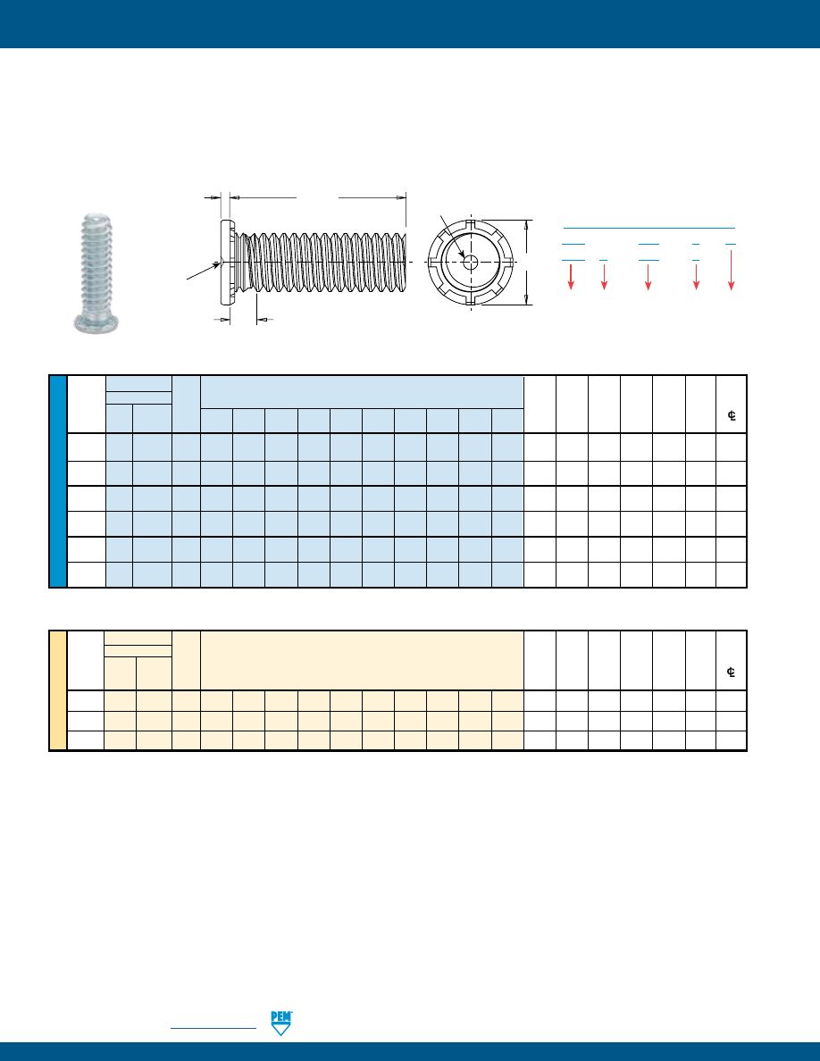
FH-8
PennEngineering •
www.pemnet.com
SELF-CLINCHING STUDS AND PINS
ME
T
RIC
U
NIF
IE
D
Type
Length Code “L” ±.015
Min.
Hole
Max.
Min.
Fastener Material
(Length Code in 16ths of an inch)
Sheet
Size
in
Hole
Dist.
Thread
Stainless
Thread
Thick-
Sheet
in
H S T Hole
Size Steel
Steel
Code
.250 .312 .375 .500 .625 .750 .875 1.00 1.25 1.50 ness +.003 Attach.
±.015 Max. Max.
(1)
-.000
Parts
(2)
to Edge
.086-56
TFH
TFHS 256 4 5 6 8 10 12 — — — — .020
.085 .105
.141 .070
.025
.187
(#2-56)
.112-40
TFH
TFHS 440 4 5 6 8 10 12 14 — — — .020 .111 .131
.176 .070
.025
.219
(#4-40)
.138-32 TFH TFHS 632 4 5 6 8 10 12 14 16 20 24 .020 .137 .157 .203 .070 .025 .250
(#6-32)
.164-32 TFH TFHS 832 4 5 6 8 10 12 14 16 20 24 .020 .163 .183 .234 .070 .025 .281
(#8-32)
.190-24 TFH TFHS 024 — 5 6 8 10 12 14 16 20 24 .020 .189 .209 .250 .090 .025 .281
(#10-24)
.190-32 TFH TFHS 032 — 5 6 8 10 12 14 16 20 24 .020 .189 .209 .250 .090 .025 .281
(#10-32)
Type
Min. Hole
Max.
Min.
Thread Fastener Material
Sheet Size in
Hole
Dist.
Size x
Stain-
Thread
Length Code “L” ±0.4
Thick- Sheet in
H S T
Hole
Pitch Steel less Code
(Length
Code
in
millimeters)
ness +0.08 Attach.
±0.4 Max. Max.
Steel
(1)
Parts
(2)
to Edge
M3 x 0.5
TFH
TFHS
M3 6 8 10 12 15 18 20 25 — — 0.51 3 3.3 4.5 1.8 0.64
5.6
M4 x 0.7 TFH TFHS M4 — 8 10 12 15 18 20 25 30 35 0.51 4 4.7 5.8 1.8 0.64 7.2
M5 x 0.8 TFH TFHS M5 — 8 10 12 15 18 20 25 30 35 0.51 5 5.3 6.4 2.3 0.64 7.2
•
Non-flush for sheets as thin as .020” / 0.51 mm.
•
TFH studs are recommended for use in steel or aluminum sheets HRB (Rockwell “B” Scale) 80 / HB (Hardness Brinell) 150 or less.
•
TFHS studs are recommended for use in steel or aluminum sheets HRB (Rockwell “B” Scale) 70 / HB (Hardness Brinell) 125 or less.
All dimensions are in inches.
All dimensions are in millimeters.
(1) See page 20 for installation tool requirements.
(2) Threads are gaugeable to within 2 pitches of the “S” Max. dimension. A class 3B/5H maximum material commercial nut shall pass up to the “S” Max.
dimension.
TFH™/TFHS™ NON-FLUSH STUDS
Type
TFH – 632 – 6
ZI
TFH S – 632 – 6
Length
Code
Thread
Code
Finish
Code
Material
Code
PART NUMBER DESIGNATION
Dimple in head
identifies TFH/
TFHS studs
T
L
H
S
unthreaded length
PEM® Dimple
Registered Trademark
Clinching profile may vary.
pem-html.html
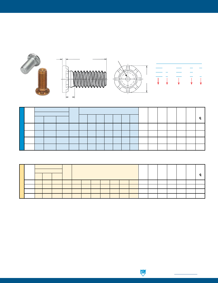
PennEngineering •
www.pemnet.com
FH-9
SELF-CLINCHING STUDS AND PINS
ME
T
RIC
U
NIF
IE
D
Type
Length Code “L” ±.015
Min. Hole Max.
Min.
Fastener Material
(Length Code in 16ths of an inch)
Sheet
Size in
Hole
Dist.
Thread
Thread
Thick- Sheet in
H S T Hole
Size Steel Stainless Phosphor
Code .500 .750 1.00 1.25 1.50 1.75 2.00
ness +.005 Attach.
±.01 Max. Max.
Steel Bronze
(1) -.000
Parts (2)
to Edge
.190-32 HFH HFHS HFHB 032 8 12 16 20 24 28 32 .050 .190 .252 .300 .105 .040 .415
(#10-32)
.250-20 HFH HFHS HFHB 0420 8 12 16 20 24 28 32 .060 .250 .312 .380 .125 .050 .460
(1/4-20)
.313-18 HFH HFHS HFHB 0518 8 12 16 20 24 28 32 .075 .312 .374 .480 .140 .070 .500
(5/16-18)
.375-16 HFH HFHS HFHB 0616 — 12 16 20 24 28 32 .090 .375 .437 .580 .155 .085 .530
(3/8-16)
Tensile strength:
HFH - 120 ksi / HFHS - 75 ksi / HFHB - 60 ksi.
Type
Min. Hole Max.
Min.
Thread
Fastener Material
Sheet
Size in Hole
Dist.
Size x
Thread
Length code “L” ±0.4
Thick- Sheet in
H S T Hole
Pitch Steel Stainless Phosphor
Code
(Length Code in millimeters)
ness +0.13 Attach.
±0.25 Max. Max.
Steel
Bronze(1) Parts (2) to Edge
M5 x 0.8 HFH HFHS HFHB M5
15
20
25
30
35
40
50 1.3 5 6.4 7.8 2.7 1.14 10.7
M6
x 1 HFH HFHS HFHB M6 15
20 25 30 35 40 50 1.5
6
7.5 9.4 2.8 1.27 11.5
M8 x 1.25 HFH HFHS HFHB M8
15
20
25
30
35 40 50 2 8 9.5 12.5 3.5 1.78 12.7
M10 x 1.5 HFH HFHS HFHB M10 15
20
25
30
35
40
50
2.3
10
11.5 15.7 4.1 2.29 13.7
Tensile strength:
HFH - 900 MPa / HFHS - 515 MPa / HFHB - 415 MPa.
•
HFH studs are for high-strength applications in sheets as thin as .050” / 1.3 mm.
•
HFHS studs offer high corrosion resistance.
•
HFHB studs are for superior electrical/mechanical attachment in copper.
•
HFH studs are recommended for use in steel or aluminum sheets HRB (Rockwell “B” Scale) 85 / HB (Hardness Brinell) 165 or less.
•
HFHS studs are recommended for use in steel or aluminum sheets HRB (Rockwell “B” Scale) 70 / HB (Hardness Brinell) 125 or less.
•
HFHB studs are recommended for use in copper sheets HRB (Rockwell “B” Scale) 55 / HB (Hardness Brinell) 83 or less.
All dimensions are in inches.
All dimensions are in millimeters.
(1) The electrical resistance (tested at 10 amps DC) between phosphor bronze studs and copper busbars is below 104µ ohms and 62µ ohms for the #10-
32 / M5 and 3/8-16 / M10 thread sizes respectively, after repeated thermal and mechanical cycling. For complete electrical resistance test data for
type HFHB studs installed in copper, see bulletin entitled “Electrical Resistance of HFHB Studs Installed in Copper” on our website.
(2) Threads are gaugeable to within 2 pitches of the “S” Max. dimension. A class 3B/5H maximum material commercial nut shall pass up to the “S” Max.
dimension.
HFH™/HFHS™/HFHB™ HEAVY-DUTY STUDS
L
H
S
T
unthreaded length
PEM® Dimple
Registered Trademark
Type
HFH – 032 – 12
ZI
HFH S – 032 – 12
HFH B – 032 – 12
X
Length
Code
Thread
Code
Finish
Code
Material
Code
PART NUMBER DESIGNATION
Clinching profile may vary.
pem-html.html
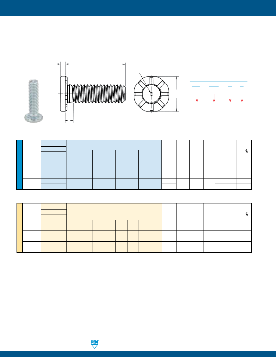
FH-10
PennEngineering •
www.pemnet.com
SELF-CLINCHING STUDS AND PINS
U
NIF
IE
D
•
Enlarged head diameter reduces stress on panel.
•
Thicker head allows for larger hole in attached panels.
•
Clinch design provides high-strength in sheets as thin as .031” / 0.8 mm.
•
Recommended for use in steel or aluminum sheets HRB (Rockwell “B” Scale) 85 / HB (Hardness Brinell) 165 or less.
Type
Min.
Hole Size
Max.
Min.
Thread
Thread Sheet
In Sheet
Hole In
H
S
T
Dist.
Size
Fastener Material
Code
Thickness +.005 Attached ±.01 Max. Max. Hole
C/L
Steel
.500 .750 1.00 1.25 1.50 1.75 2.00 (1)
-.000
Parts
(2)
To Edge
.190-32
HFE
032 8 12 16 20 24 28 32 .040 .190 .280 .357 .102 .048 .360
(#10-32)
.250-20 HFE 0420 8 12 16 20 24 28 32 .040 .250 .340 .462 .118 .060 .470
(1/4-20) THFE
.031
.109
.069
.446
.313-18 HFE 0518 8 12 16 20 24 28 32 .060 .312 .402 .586 .133 .083 .560
(5/16-18) THFE
.031
.117
.099
.596
Tensile strength:
120 ksi
Tensile strength:
900 MPa
All dimensions are in inches.
All dimensions are in millimeters.
(1) See page 21 for installation tool requirements.
(2) Threads are gaugeable to within 2 pitches of the “S” Max. dimension. A class 3B/5H maximum material commercial nut shall pass up to the “S” Max.
dimension.
HFE™/THFE™ HEAVY DUTY STUDS FOR THIN SHEETS
T
L
H
S
unthreaded length
PEM® Dimple
Registered Trademark
Type
HFE – 0420 – 12
ZI
THFE – 0420 – 12
ZI
Length
Code
Thread
Code
Finish
Code
PART NUMBER DESIGNATION
Length Code “L” ±.015
(Length Code in 16ths of an inch)
ME
T
RIC
Thread
Type
Min. Hole Max. Min.
Size x
Thread Sheet
Size
Hole In
H
S
T
Dist.
Pitch
Fastener Material
Code
Thickness In Sheet Attached
±0.25
Max.
Max.
Hole
C/L
Steel
(1)
+0.13
Parts
(2)
To Edge
M5 x 0.8
HFE
M5 15 20 25 30 35 40 50 1
5
7.3 9.6 2.6 1.35 10
M6 x 1
HFE
M6 15 20 25 30 35 40 50
1
6 8.3 11.35
2.8 1.52 11.5
THFE
0.8
2.62
1.7
10.5
M8 x 1.25
HFE
M8 15 20 25 30 35 40 50
1.5
8 10.3 15.3
3.3 2.13 14.5
THFE
0.8
2.9
2.54
15
Length Code “L” ±0.4
(Length Code in millimeters)
Clinching profile may vary.
pem-html.html
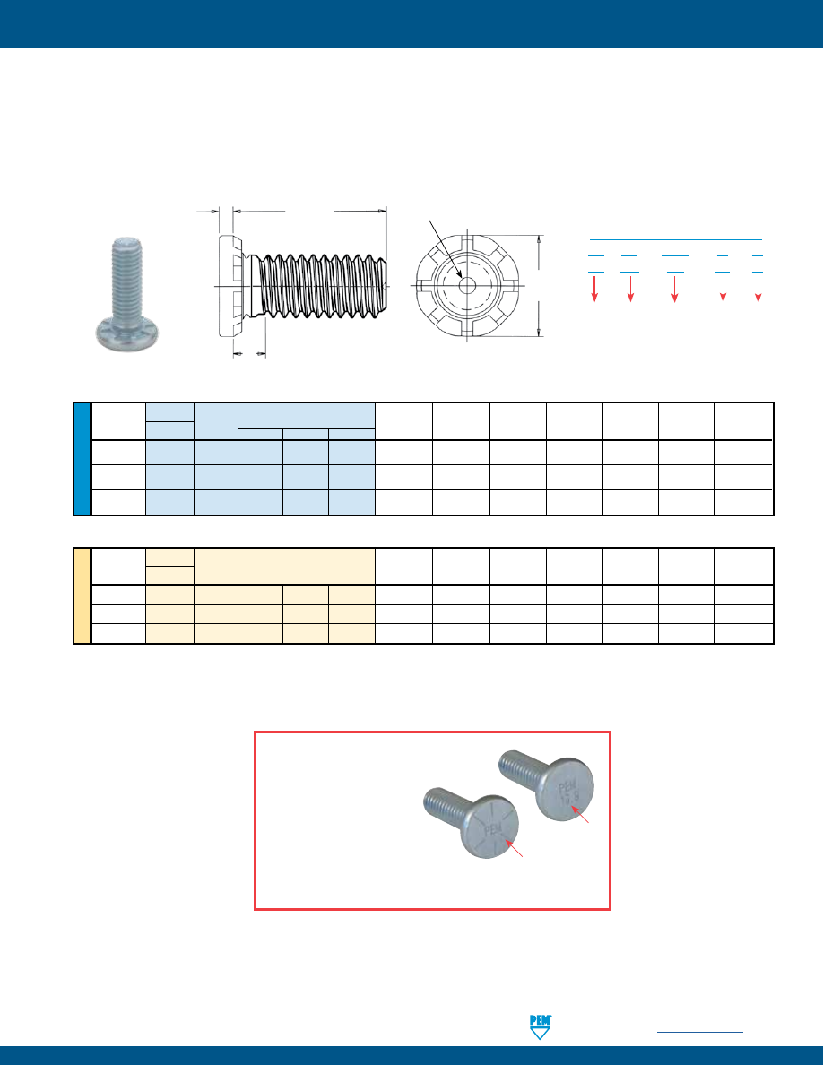
PennEngineering •
www.pemnet.com
FH-11
SELF-CLINCHING STUDS AND PINS
All dimensions are in inches.
All dimensions are in millimeters.
U
NIF
IE
D
Thread
Type
Min.
Hole Size
Max. Hole
S
Min. Dist.
Size
Thread
Sheet
in Sheet
in Attached
H
Max.
T
Hole C/L
Steel Code
.500 .750 1.00
Thickness
+.005 –.000
Parts
±.01
(2)
Max.
To Edge
.190-32
HFG8 032 8 12 16 .040 .190 .280 .391 .105 .077 .469
(#10-32)
.250-20
HFG8 0420 8 12 16
.040
.250
.340
.507
.125
.090
.709
(1/4-20)
.313-18
HFG8 0518 — 12 16
.060
.312
.402
.645
.140
.126
.827
(5/16-18)
Length Code “L” ±.015
(1)
(Length Code in 16ths of an inch)
ME
T
RIC
Thread
Type
Min.
Hole Size
Max. Hole
S
Min. Dist.
Size x
Thread
Sheet
in Sheet
in Attached
H
Max.
T
Hole C/L
Pitch
Steel Code
Thickness
+0.13 Parts ±0.25 (2) Max.
To
Edge
M5 x 0.8
HF109
M5
15
20
25
1 5 7.3 10.3 2.6 2.06 11.5
M6 x 1
HF109
M6
15
20
25
1
6
8.3
12.1
2.7
2.29
18.0
M8 x 1.25
HF109
M8
—
20
25
1.5
8
10.3
16.6
3.4
3.25
21.0
Length Code “L” ±0.4
(1)
(Length Code in millimeters)
•
HFG8 and HF109 studs are for heavy-duty applications in sheets as thin as .040” / 1 mm.
•
Grade 8 and property class 10.9 studs meeting 150 ksi/1040 MPa minimum.
•
Recommended for use in steel or HSLA steel sheets HRB (Rockwell “B” Scale) 89 / HB (Hardness Brinell) 180 or less.
•
Large head diameter spreads compressive stress on panel.
HFG8™/HF109™ HEAVY DUTY, HIGH TENSILE STRENGTH STUDS
HFG8 Marking
*
To be sure that you are getting
genuine PEM products, look for the
PEM stamp. Studs within
the size range of the SAE
and ISO specs are also
identified with the Grade
8 and 10.9 head markings
respectively.
*
Thread size #10-32 does not have SAE head marking since it is technically
not within the size range of the specification.
(1) Other lengths available up to a maximum of 1.5” (unified) and 40 mm (metric) on special order.
(2) Threads are gaugeable to within 2 pitches of the “S” Max. dimension. A class 3B/5H maximum material
commercial nut shall pass up to the “S” Max. dimension.
L
H
S
T
unthreaded length
PEM® Dimple
Registered Trademark
Type
HF G8 – 0420 – 12
ZI
HF 109 – M6 – 20
ZI
Length
Code
Thread
Code
Finish
Code
Strength
Code
PART NUMBER DESIGNATION
Tensile strength:
150 ksi
Tensile strength:
1040 MPa
Clinching profile may vary.
pem-html.html
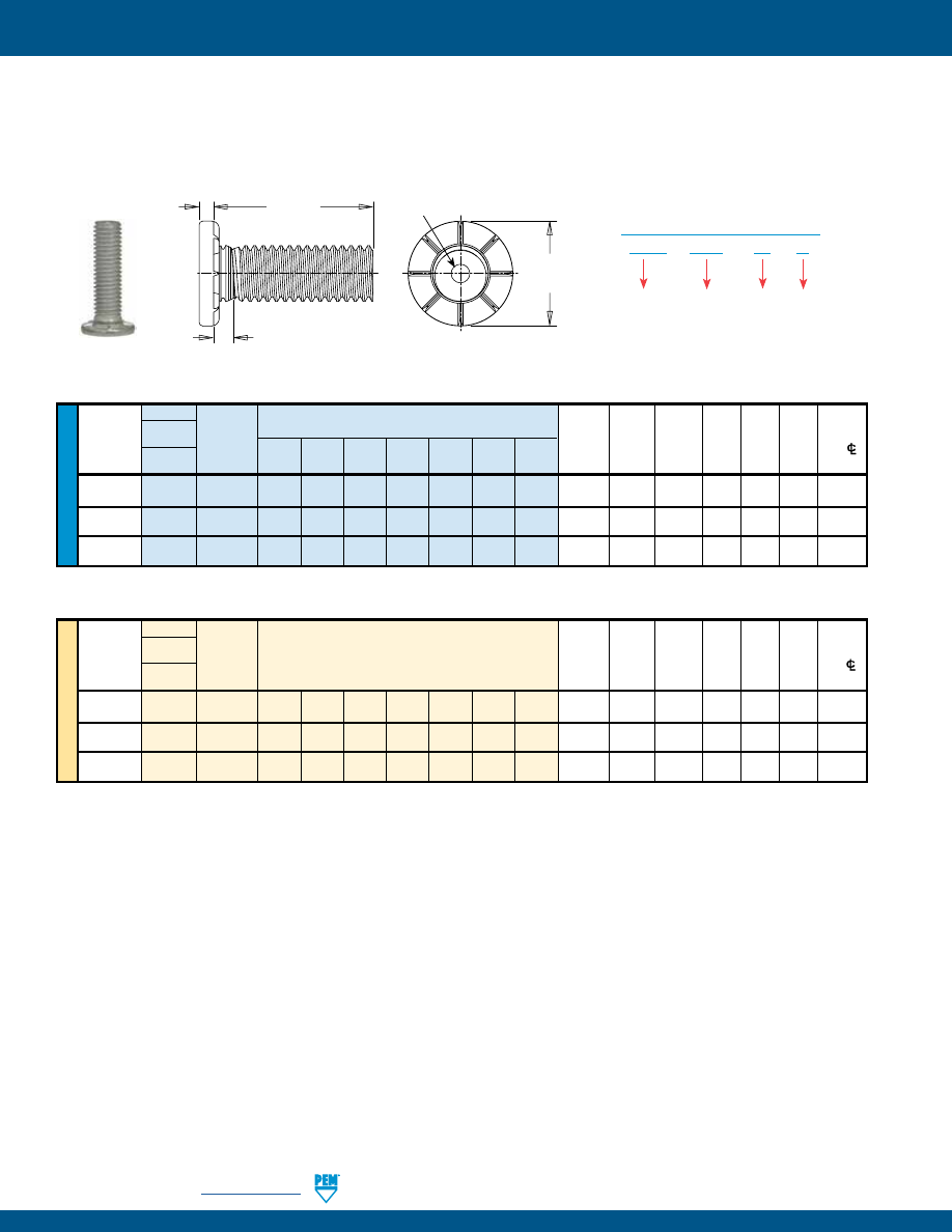
FH-12
PennEngineering •
www.pemnet.com
SELF-CLINCHING STUDS AND PINS
HFLH™ HARD PANEL STUDS
•
Installs into thinner, harder, high strength steel materials
•
Recommended for use in s500 HSLA sheets up to 700MPa (hardness up to 96 HRB)
Type
HFLH – 0420 – 20
ZI
Length
Code
Thread
Code
Finish
Code
PART NUMBER DESIGNATION
U
NIF
IE
D
Type
Length Code “L” ±.015
Thread Fastener Thread
(Length Code in 16ths of an inch)
Min.
Hole Size Max.
H S T
Min.
Size
Material
Code
Sheet
In Sheet Hole In
±.01 Max. Max.
Dist.
Hardened
Thickness +.005 Attached Hole
C/L
Alloy Steel
(1)
-.000
Parts (2) To Edge
.190-32
HFLH
032
8
12 16 20 24 28 32 .040 .190 .280 .357 .102 .048 .360
(#10-32)
.250-20
HFLH
0420
8 12 16 20 24 28 32 .040 .250 .340 .462 .118 .060 .470
(1/4-20)
.313-18
HFLH
0518
8
12 16 20 24 28 32 .060 .312 .402 .586 .133 .083 .560
(5/16-18)
Tensile strength:
120 ksi
.500 .750 1.00 1.25 1.50 1.75 2.00
All dimensions are in inches.
ME
T
RIC
Type
Thread
Fastener
Thread
Length Code “L” ±.0.4
Min.
Hole Size
Max.
H S T
Min.
Size x
Material
Code
(Length Code in millimeters)
Sheet
In Sheet
Hole In
±0.25 Max. Max.
Dist.
Pitch Hardened
Thickness +0.13 Attached Hole
C/L
Alloy
Steel
(1) Parts (2) To Edge
M5 x 0.8 HFLH M5 15 20 25 30 35 40 50
1
5
7.3 9.6 2.6 1.35 10
M6 x 1
HFLH
M6
15 20 25 30 35 40 50 1
6 8.3 11.35 2.8 1.52 11.5
M8 x 1.25
HFLH
M8
15 20 25 30 35 40 50 1.5
8 10.3 15.3 3.3 2.13 14.5
Tensile strength:
900 MPa
All dimensions are in millimeters.
(1) See page 21 for installation tool requirements.
(2) Threads are gaugeable to within 2 pitches of the “S” Max. dimension. A class 3B/5H maximum material commercial nut shall pass up to the “S” Max.
dimension.
(3) See PEM Technical Support section of our web site (www.pemnet.com) for related plating standards and specifications.
(4) “X” suffix studs may have pitch diameters and major diameters below 2A “Basic”, per ANSI B1.1, Section 7, and B1.13M, Section 8 to allow for minimum
of 0.0002” / 0.0051 mm of plating.
T
L
H
S
unthreaded length
PEM® Dimple
Registered Trademark
pem-html.html
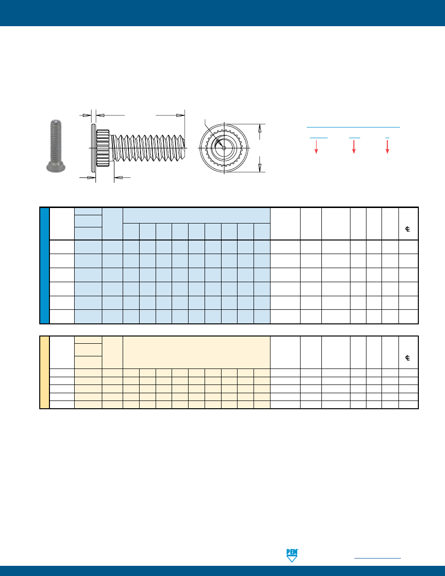
PennEngineering •
www.pemnet.com
FH-13
SELF-CLINCHING STUDS AND PINS
All dimensions are in inches.
All dimensions are in millimeters.
U
NIF
IE
D
Type
Length Code “L” ±.015
Hole
Hole
Min.
Fastener
(Length Code in 16ths of an inch)
Size in
Dia. of
Dist.
Thread
Material
Thread Sheet Sheet
Attached H
S T Hole
Size
Stainless
Code
.312 .375 .500 .625 .750 .875 1.00 1.25 1.50 Thickness +.003 Panel
±.010 Max. ±.004
Steel (2) -.000
+.005
–.000 (3)
to Edge
.086-56
SGPC
256
5
6
8
10
12
—
—
—
—
.024 - .047
.145
.182
.189 .093
.020
.130
(#2-56)
.112-40
SGPC
440
5
6
8
10
12
14
16
20
—
.024 - .047
.171
.205
.228
.101
.024
.160
(#4-40)
.138-32
SGPC
632
5
6
8
10
12
14
16
20
24
.024 - .047
.196
.229
.256 .109
.024
.180
(#6-32)
.164-32
SGPC
832
5
6
8
10
12
14
16
20
24
.024 - .047
.223
.259
.279 .109
.024
.200
(#8-32)
.190-32
SGPC
032
5
6
8
10
12
14
16
20
24
.024 - .047
.249
.280
.307 .109
.024
.210
(#10-32)
.250-20
SGPC
0420
—
6
8
10
12
14
16
20
24
.024 - .047
.309
.343
.366
.131
.028
.250
(1/4-20)
ME
TR
IC
Type
Hole
Min.
Fastener
Hole Dia.
of Dist.
Thread
Material
Thread
Length Code “L” ±0.4
Sheet
Size in
Attached
H
S T Hole
Size x
Stainless
Code
(Length Code in millimeters) Thickness Sheet Panel
±0.25 Max. ±0.1
Pitch
Steel (2) +0.08 +0.13
(3)
to Edge
M2.5 x 0.45
SGPC
M2.5
8
10
12
15
18
—
—
—
—
0.6 - 1.2
4
4.95
5
2.4
0.5
3.9
M3 x 0.5
SGPC
M3
8
10
12
15
18
20
25
—
—
0.6 - 1.2
4.5
5.45
6
2.5
0.6
4.3
M4 x 0.7
SGPC
M4
8
10
12
15
18
20
25
30
—
0.6 - 1.2
5.5
6.3
7
2.7
0.6
4.9
M5 x 0.8
SGPC
M5
8
10
12
15
18
20
25
30
35
0.6 - 1.2
6.5
7.45
8
2.8
0.6
5.5
M6 x 1
SGPC
M6
—
10
12
15
18
20
25
30
35
0.6 - 1.2
7.5
8.3
9
3
0.7
6.2
(1) When using the fastener to attach more than one sheet or panel, the stud may seem slightly loose after installation. This is a normal condition in some
applications and will not effect the stud’s performance.
(2) See page 23 for installation tooling requirements. Contact Technical Support (techsupport@pemnet.com) for other thicknesses.
(3) Threads are gaugeable to within 2 pitches on the “S” Max. dimension. A class 3B/5H maximum material commercial nut shall pass up to the “S” Max.
dimension.
SGPC – 632 – 8
PART NUMBER DESIGNATION
Type
Thread
Code
Length
Code
•
Installs into sheets as thin as .024” / 0.6 mm.
•
Can be used to attach dissimilar materials.
•
Can accommodate multiple panels as long as the total thickness does not exceed the maximum sheet thickness.
(1)
•
Can be installed into most materials, including stainless steel and rigid non-metallic panels.
•
Allows for close centerline-to-edge distance.
SGPC™ SWAGING COLLAR STUDS
H
L
T
S
PEM® Dimple
Registered Trademark
unthreaded length
Clinching profile may vary.
pem-html.html
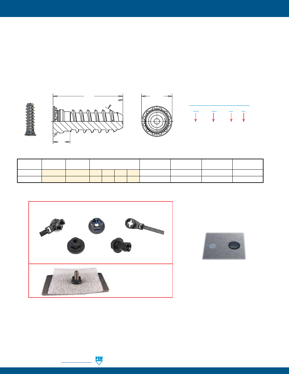
FH-14
PennEngineering •
www.pemnet.com
SELF-CLINCHING STUDS AND PINS
L
H
S
unthreaded length
65˚ Nom.
Thread Size
Type
Thread
Length Code ”L” ±0.4
Min. Sheet
Hole Size in Sheet
H
S
x Pitch
Code
(Length Code in millimeters)
Thickness
+0.08
±0.4
Max.
5 mm x 1.6
FH
X5
10 15 20 25
1
5.2
6.5
4
6 mm x 1.6
FH
X6
10
15
20
25
1.6
6.2
8.2
4
All dimensions are in millimeters.
FHX™ FLUSH-HEAD STUDS WITH X-PRESS™ THREAD PROFILE
FOR USE WITH PUSH ON PLASTIC MATING FASTENERS
•
Offers fast, reliable attachment.
•
Coarse thread design of the thread reduces assembly time and provides high retention force.
•
Allows for lighter assembly.
•
Self-clinching stud mounts flush in metal sheets as thin as 1mm.
•
Thread design accommodates paints and coatings without compromising performance.
•
Self-clinching technology is cleaner and has a more attractive finished appearance than welding.
•
Can be installed during the stamping process with PEMSERTER® in-die technology.
Type
FH – X5 – 10
ZI
Length
Code
Thread
Code
Finish
Code
PART NUMBER DESIGNATION
Examples of plastic nuts and wire tie products that
can be used with PEM
®
X-Press™ studs.
Contact Tech Support for more information.
Press-on (kwik) nut can
be used to hold down soft
materials such as foam,
cloth or insulation.
Standard head mounts flush in
sheet. Domed head available on
special order.
(1) See page 23 for installation tool requirements.
pem-html.html
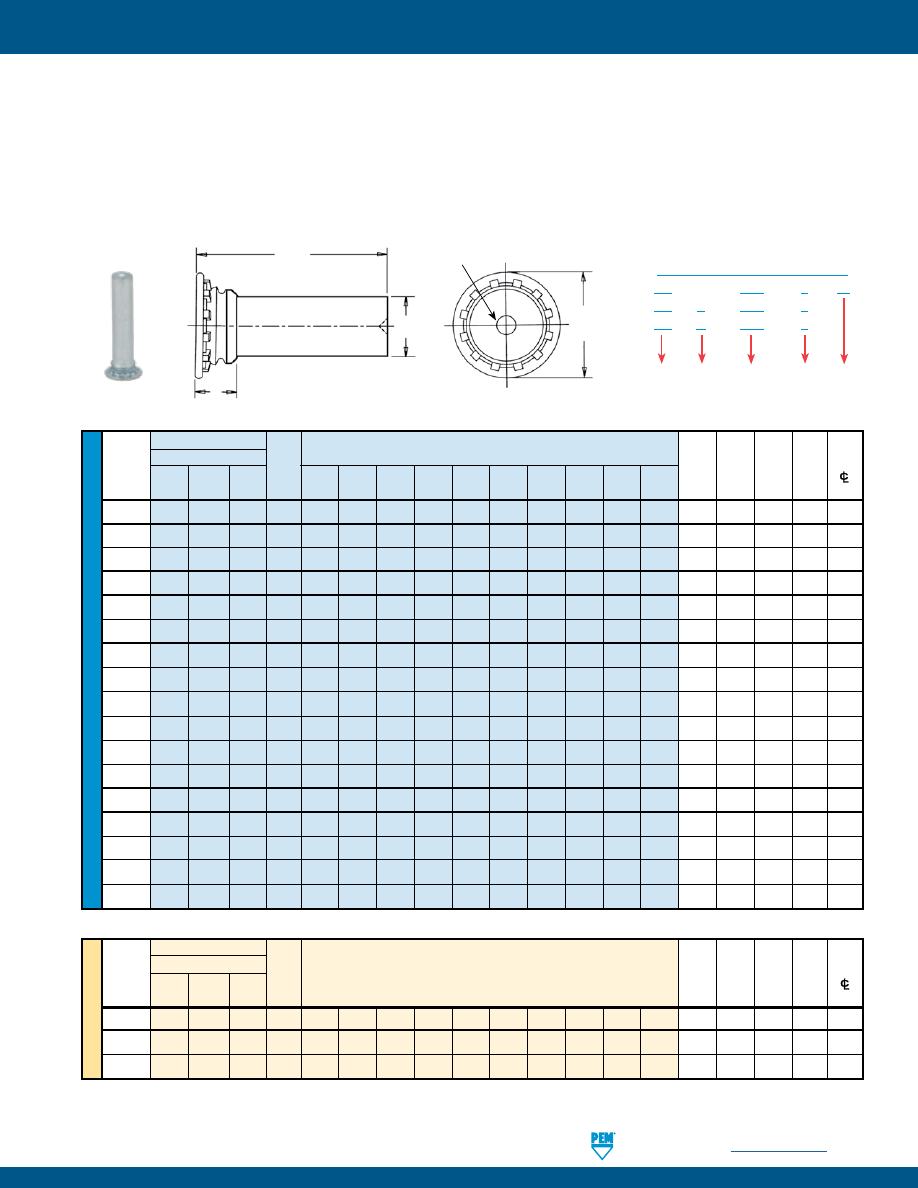
PennEngineering •
www.pemnet.com
FH-15
SELF-CLINCHING STUDS AND PINS
ME
T
RIC
U
NIF
IE
D
Type Length Code “L” ±.015
Hole
Min.
Nominal
Fastener Material
Pin
(Length Code in 16ths of an inch)
Min. Size in
Dist.
Pin Dia.
Sheet Sheet H S Hole
Diameter
Steel Stainless Alu-
Code
.250 .312 .375 .500 .625 .750 .875 1.00 1.25 1.50
Thick- +.003 ± .015 Max.
P±.002
Steel minum
ness -.000 (1)
to Edge
.073 FH FHS FHA
073 4 5 6 8 10 — — — — — .040
.085 .15 .075
.19
.084 FH FHS FHA
084 4 5 6 8 10 12 — — — — .040
.099 .16
.085
.22
.094 FH FHS FHA
094 4 5 6 8 10 12 — — — — .040 .111 .18
.085
.22
.103 FH FHS FHA
103 4 5 6 8 10 12 — — — — .040
.118 .18
.085
.22
.106 FH FHS FHA 106 4 5 6 8 10 12 14 16 20 — .040 .125 .19 .090 .22
.116 FH FHS FHA 116 4 5
6
8 10 12
14 16 20 — .040 .137 .21 .090 .25
.120 FH FHS FHA 120 4
5
6
8
10 12
14 16 20 24 .040 .137 .21 .090 .25
.137 FH FHS FHA 137 4
5
6
8
10 12
14 16 20 24 .040 .157 .23 .090 .28
.141 FH FHS FHA 141 4 5
6
8 10 12
14 16 20 24 .040 .163 .24 .090 .28
.160 FH FHS FHA 160 4
5
6
8
10 12
14 16 20 24 .040 .189 .26 .100 .28
.167 FH FHS FHA 167 — 5
6
8
10 12
14 16 20 24 .040 .189 .26 .100 .28
.173 FH FHS FHA 173 — 5 6 8 10 12 14 16 20 24 .040 .197 .26 .100 .28
.207 FH FHS FHA 207 — 5 6 8 10 12 14 16 20 24 .062 .236 .32 .135 .31
.215 FH FHS FHA 215 — —
—
8
10 12
14 16 20 24 .062 .250 .34 .135 .31
.223 FH FHS FHA 223 — —
—
8
10
12
14
16 20 24 .062 .250 .34 .135 .31
.273 FH FHS FHA 273 — —
—
8
10
12
14
16 20 24 .093 .312 .38 .160 .38
.281 FH FHS FHA 281 — —
—
8
10 12
14 16 20 24 .093 .312 .38 .160 .38
•
Flush-head for sheet thickness of .040” / 1 mm and greater.
•
FH pins are recommended for use in steel or aluminum sheets HRB (Rockwell “B” Scale) 80 / HB (Hardness Brinell) 150 or less.
•
FHS pins are recommended for use in steel or aluminum sheets HRB (Rockwell “B” Scale) 70 / HB (Hardness Brinell) 125 or less.
•
FHA pins are recommended for use in aluminum sheets HRB (Rockwell “B” Scale) 50 / HB (Hardness Brinell) 82 or less.
Type
Min.
Nominal
Fastener Material
Pin
Min.
Hole Dist.
Pin
Dia.
Length Code “L” ±0.4
Sheet Size in
H S
Hole
Diameter
Steel Stainless Alu-
Code
(Length Code in millimeters)
Thick- Sheet
± 0.4
Max.
P±0.05
Steel minum
ness +0.08 (1) to Edge
3
FH FHS FHA 3MM 6 8 10 12 15 18 20 25 30 — 1 3.5 5.3 2.3 6.4
4
FH FHS FHA 4MM — 8 10 12 15 18 20 25 30 35 1 4.1 6 2.3 7.1
5
FH FHS FHA 5MM — 8 10 12 15 18 20 25 30 35 1 5.5 7.5 2.55 7.6
(1) Pin diameter may exceed max. in this region.
These PEM® pins are only available on special order. See TPS, TP4, and TPXS pins on page 16 for standard diameter pins.
All dimensions are in inches.
All dimensions are in millimeters.
FH™/FHS™/FHA™ FLUSH-HEAD PINS
L
H
S
P
PEM® Dimple
Registered Trademark
Type
FH – 094 – 6
ZI
FH
S – 094 – 6
FH
A – 094 – 6
Length
Code
Pin
Diameter
Code
Finish
Code
Material
Code
PART NUMBER DESIGNATION
Clinching profile may vary.
pem-html.html
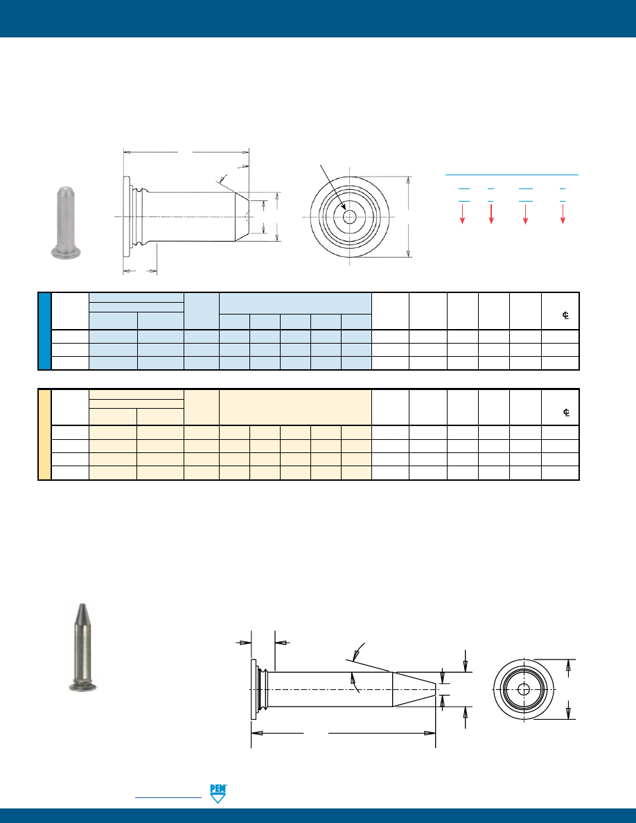
FH-16
PennEngineering •
www.pemnet.com
SELF-CLINCHING STUDS AND PINS
ME
T
RIC
U
NIF
IE
D
Type
Min.
Pin Fastener Material
Pin Min.
Hole Size D H S Distance
Diameter
300 Series
400 Series
Diameter
Sheet
in Sheet ±.006 ±.015 Max. Hole
C/L
P ±.002
Stainless Steel
Stainless Steel
Code
.375 .500 .625 .750 1.00
Thickness
+.003 -.000 (1)
to Edge
.125
TPS
TP4
125 6 8 10 12 — .040 .144 .090 .205 .090 .250
.187
TPS
TP4
187
6
8
10
12
16
.040
.205
.132 .270 .090 .280
.250
TPS
TP4
250
—
8
10
12
16
.040
.272
.177 .335 .090
.310
Type
Min.
Pin Fastener Material
Pin Min.
Hole Size D H S Distance
Diameter
300 Series
400 Series
Diameter
Sheet
in Sheet ±0.15 ±0.4 Max. Hole
C/L
P ±0.05
Stainless Steel
Stainless Steel
Code
Thickness +0.08 (1)
to Edge
3
TPS
TP4 3MM 8 10 12 16 — 1
3.5 2.11 5.2 2.29 6.4
4
TPS
TP4
4MM 8 10 12 16 —
1
4.5 2.82 6.12 2.29 7.1
5
TPS
TP4
5MM
— 10 12 16 20 1 5.5 3.53 7.19 2.29 7.6
6
TPS
TP4
6MM — — 12 16 20 1
6.5 4.24 8.13 2.29 7.9
(1) Pin diameter may exceed max. in this region.
If your application requires corrosion resistant fasteners, non-magnetic fasteners, or will be exposed to temperatures above 300˚ F (149˚ C),
see note at bottom of page 6 about “400 series fasteners for stainless steel panels”.
•
Flush-head for sheet thickness of .040” / 1 mm and greater.
•
Satisfies a wide range of positioning, pivot, and alignment applications.
•
Chamfered end makes mating hole location easy.
•
TPS pins are recommended for use in steel or aluminum sheets HRB (Rockwell “B” Scale) 70 / HB (Hardness Brinell) 125 or less.
•
TP4 pins are recommended for use in stainless steel sheets HRB (Rockwell “B” Scale) 92 / HB (Hardness Brinell) 195 or less.
All dimensions are in inches.
All dimensions are in millimeters.
•
Meets the ATCA PICMG 3.0 specification.
•
15
˚
tapered point makes engaging the mating hole easy.
TPXS™
SELF-CLINCHING PILOT PINS
Min. Sheet Thickness:
1 mm
Hole Size In Sheet:
3.5 mm +0.08
Min. Dist. Hole C/L To Edge:
6.4 mm
Length Code “L” ± .015
(Length Code in 16ths of an inch)
Length Code “L” ± 0.4
(Length Code in millimeters)
TPS™/TP4™ FLUSH-HEAD PILOT PINS
H
L
64° ±5°
S
P
D
PEM® Dimple
Registered Trademark
(1) Pin diameter may exceed max. in this region.
1 mm
±0.15
3 mm
±0.05
5.2 mm
±0.4
16 mm
±0.25
15˚
±5˚
2.29 mm
Max.
(1)
PEM® Part Number: TPXS-3MM-16
Type
TP
S – 187 – 8
TP
4 – 187 – 8
Length
Code
Pin
Diameter
Code
Material
Code
PART NUMBER DESIGNATION
Clinching profile may vary.
Clinching profile may vary.
pem-html.html
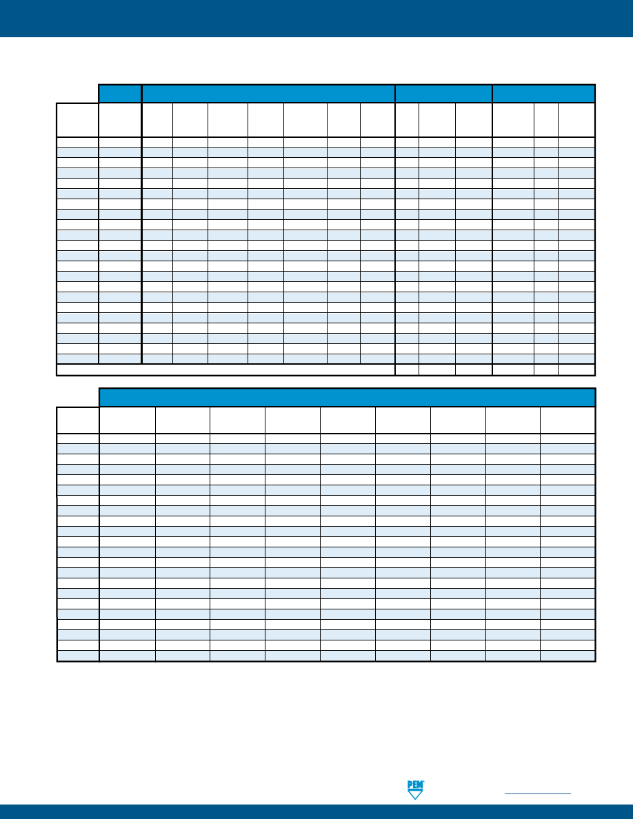
PennEngineering •
www.pemnet.com
FH-17
SELF-CLINCHING STUDS AND PINS
(1) For plated studs, Class 2A/6g, the maximum major and pitch diameter, after plating, may equal basic sizes and be gauged to Class 3A/4h. Per ASME
B1.1, Section 7, Paragraph 7.2 and ASME B1.13M, Section 8, paragraph 8.2.
(2) Special order with additional charge.
(3) Part numbers for aluminum studs have no finish suffix.
(4) “X” suffix studs may have pitch diameters and major diameters below 2A/6g minimum size, per ANSI B1.1, Section 7, and B1.13M, Section 8 to allow for
minimum of 0.0002” / 0.0051 mm of plating.
(5) See PEM Technical Support section of our web site for related plating standards and specifications.
(6) With rust preventative oil.
(7) HRB - Hardness Rockwell “B” Scale. HB - Hardness Brinell.
MATERIAL AND FINISH SPECIFICATIONS
External,
Hardened
Age
Zinc plated
Passivated
ASME B1.1,
Hardened
Medium
CDA 510
Hardened
300 Series 400 Series
No
5µm,
and/or
Zinc plated
No
Rust
Type
2A / ASME
Carbon
Carbon
Aluminum
Phosphor
A286 Stainless Stainless
Stainless
Finish
Colorless
Tested Per
5µm, Yellow
Finish Preventative
B1.13M, 6g
Steel
Alloy Steel (plain finish)
Bronze
Steel
Steel
Steel
(4)
(5)
ASTM A380
(5)
(4)
Oil
FH
• •
• •
FHS
• • •
FHA
•
•
•
(3)
FH4
• •
•
FHP
• • •
FHL
• •
• •
FHLS
• • •
TFH
• •
• •
TFHS
• • •
HFE
• •
• •
THFE
• •
• •
HFH
• •
• •
HFHB
• •
•
HFHS
• • •
HFG8
• •
• •
HF109
• •
• •
HFLH
•
•
•
•
(6)
SGPC
•
• •
FHX
•
•
•
TPS
• •
TP4
• •
TPXS
• •
Part Number Codes for Finishes
X
ZI
None ZC X X
Threads
(1)
Fastener Materials
Standard Finishes
Optional Finishes
(2)
HRB 50 /
HRB 55 /
HRB 70 /
HRB 80 /
HRB 85 /
HRB 89 /
HRB 92 /
HRB 96 /
HB 82
HB 83
HB 125
HB 150
HB 165
HB 180
HB 195
HB 216
Any Sheet
Type
or Less
or Less
or Less
or Less
or Less
or Less
or Less
or Less
Hardness
FH
•
FHS
•
FHA
•
FH4
•
FHP
•
FHL
•
FHLS
•
TFH
•
TFHS
•
HFE
•
THFE
•
HFH
•
HFHB
•
HFHS
•
HFG8
•
HF109
•
HFLH
•
SGPC
•
FHX
•
TPS
•
TP4
•
TPXS
•
For use in Sheet Hardness
(7)
pem-html.html
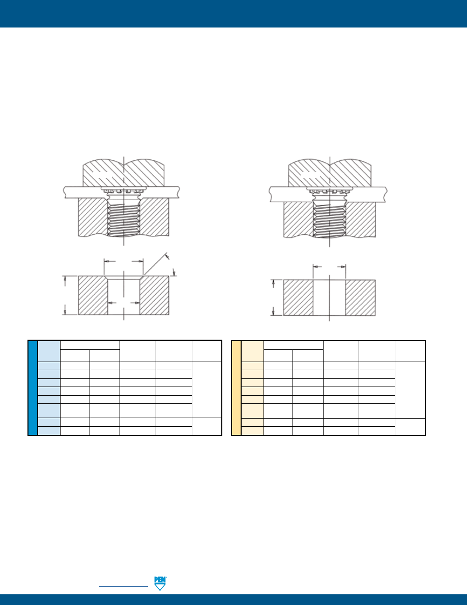
FH-18
PennEngineering •
www.pemnet.com
SELF-CLINCHING STUDS AND PINS
INSTALLATION - FH™/FHS™/FHA™ THREADED STUDS
1.
Prepare properly sized mounting hole in sheet. Do not perform any secondary operations such as deburring.
2.
Insert stud through mounting hole (punch side) of sheet and into anvil hole.
3.
With punch and anvil surfaces parallel, apply squeezing force to embed the head of the stud flush in the sheet. In most cases,
when using sheets .060” / 1.51 mm and thicker, the anvil requires only a straight thru hole to accommodate the stud (see
illustrations below for details). For sheets less than .060 / 1.51 mm, the hole requires a countersink with dimension A at the top to
provide for metal flow around the shank of the stud.
Tooling for sheet thicknesses less than .060 / 1.51 mm with #2 thru
#10 / M3 thru M5 thread sizes and less than .093” / 2.36 mm for
1/4” / M6 threads.
Tooling for sheet thicknesses .060” / 1.51 mm and greater with #2
thru #10 / M3 thru M5 thread sizes and .093” / 2.36 mm and greater
for 1/4” and 5/16” / M6 and M8 threads.
A
C
L +.125”/
3.18 mm Min.
45° Nom.
SHEET
PUNCH
ANVIL
U
NIF
IE
D
ME
T
RIC
Thread Anvil Dimensions (in.)
Anvil Part No.
Anvil Part No.
Punch
Code A C For Sheets
For Sheets
Part
> .060”
<_ .059” Number
256
.110-.114
.087-.090 970200005300 970200240300
440
.136-.140
.113-.116
970200006300 970200241300
632
.162-.166
.139-.142 970200007300 970200243300 975200048
832
.188-.192
.165-.168 970200008300 970200245300
024/032
.216-.220
.191-.194
970200009300 970200246300
For Sheets
For Sheets
> .093”
<_ .092”
0420 .295-.300 .250-.253 970200010300 970200249300 975200048
0518 .334-338 .3125-.3155 970200011300
—
Thread Anvil Dimensions (mm)
Anvil Part No.
Anvil Part No.
Punch
Code
A + 0.1
C + 0.08
For Sheets
For Sheets
Part
> 1.51 mm
<_ 1.5 mm Number
M2.5
3.1
2.53
970200300300 970200493300
M3
3.6
3.03
970200229300 970200242300
M3.5
4.1
3.53
970200007300 970200243300 975200048
M4
4.6
4.03
970200019300 970200244300
M5
5.6
5.03
970200020300 970200247300
For Sheets
For Sheets
> 2.36 mm
<_ 2.36 mm
M6
6.6
6.03
970200230300 970200248300
975200048
M8 8.6 8.03 970200231300 —
C
SHEET
PUNCH
ANVIL
L +.125”/
3.18 mm Min.
See page 5 for “L”.
PEMSERTER® Installation Tooling
pem-html.html
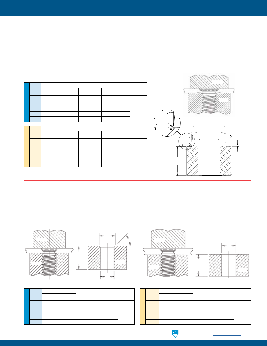
PennEngineering •
www.pemnet.com
FH-19
SELF-CLINCHING STUDS AND PINS
INSTALLATION - FH4™/FHP™ STUDS FOR STAINLESS STEEL SHEETS
1.
Prepare properly sized mounting hole in sheet. Do not perform any secondary operations such as deburring.
2.
Insert stud through mounting hole (punch side) of sheet and into anvil hole.
3.
With punch and anvil surfaces parallel, apply squeezing force to embed the head of the stud flush in the sheet.
For FH4/FHP studs, a special anvil with a raised ring is required to create a proper installation. The raised ring acts as a second displacer of the stainless
sheet material, thereby ensuring that the annular groove is filled. Please see page 6 for recommended sheet thickness range.
The special anvils are available from PEM stock or can be machined from suitable tool steel. A hardness of HRC 55 / HB 547 minimum is required to provide
long anvil life. We recommend measuring the “P” dimension every 5000 installations to ensure that the anvil remains within specification.
ME
TR
IC
U
NIF
IE
D
Thread
Anvil Dimensions (in.)
Anvil Part
Punch Part
Code
A B C P R
1
R
2
Number Number
+.003 -.000 ±.002 ±.002
±.001
Max.
Max.
440 .113 .144 .174 .010 .003 .005 8001645
632
.140
.170 .200 .010 .003 .005 8001644
832
.166
.202 .236 .010 .003 .005 8001643 975200048
032
.191
.235 .275 .010 .003 .005 8001642
0420
.252
.324 .360
.020 .003
.005
8002535
Thread
Anvil Dimensions (mm)
Anvil Part
Punch Part
Code
A B C P R
1
R
2
Number Number
+0.08 ±0.05 ±0.05 ±.025 Max. Max.
M3
3.05
3.81 4.57 0.25 0.08 0.13 8001678
M4
4.04
4.95 5.82 0.25 0.08 0.13 8001677
975200048
M5
5.08
6.15 7.16 0.25 0.08 0.13 8001676
M6 6.05 7.87 8.79 0.51 0.08 0.13 8002536
Recommended Installation Anvil
C
B
A
P
95°
Nom.
R
1
R
2
L +.125”/
3.18 mm Min.
45° Nom.
95°
Nom.
R
1
R
2
See page 6
for “L”.
INSTALLATION - FHL™/FHLS™ STUDS
1.
Prepare properly sized mounting hole in sheet. Do not perform any secondary operations such as deburring.
2.
Insert stud through mounting hole (punch side) of sheet and into anvil hole.
3.
With punch and anvil surfaces parallel, apply squeezing force to embed the head of the stud flush in the sheet. For sheets .060” /
1.51 mm and thicker, the anvil requires only a straight thru hole to accommodate the stud. For sheets less than .060” / 1.51 mm, the
hole requires a countersink with dimension A at the top to provide for metal flow around the shank of the stud.
Tooling for sheet thicknesses less than .060” / 1.51 mm.
Tooling for sheet thicknesses .060” / 1.51 mm and greater.
A
C
SHEET
PUNCH
ANVIL
ANVIL
L +.125”/
3.18 mm
Min.
45° Nom.
See page 7 for “L”.
PUNCH
SHEET
ANVIL
U
NIF
IE
D
ME
T
RIC
Thread Anvil Dimensions (in.)
Anvil Part No.
Anvil Part No.
Punch
Code A C For Sheets
For Sheets
Part
> .060”
<_ .059” Number
256
.110-.114
.087-.090
8003313
8003297
440
.136-.140
.113-.116
8003618
8003298
632
.162-.166
.139-.142
8003314
8003299
975200997
832
.188-.192
.165-.168
8003315
8003300
032
.216-.220
.191-.194
8003619
8003301
Thread Anvil Dimensions (mm)
Anvil Part No.
Anvil Part No.
Punch
Code
A C
For Sheets
For Sheets
Part
±0.05
+0.08
> 1.51 mm
<_ 1.5 mm Number
M2.5
3.1
2.53
8003316
8003302
M3
3.6
3.03
8003317
8003303
M3.5
4.1
3.53
8003318
8003304
975200997
M4
4.6
4.03
8003620
8003305
M5
5.6
5.03
8003319
8003306
C
PUNCH
ANVIL
ANVIL
SHEET
L +.125”/
3.18 mm
Min.
See page 7 for “L”.
PEMSERTER® Installation Tooling
PEMSERTER® Installation Tooling
pem-html.html
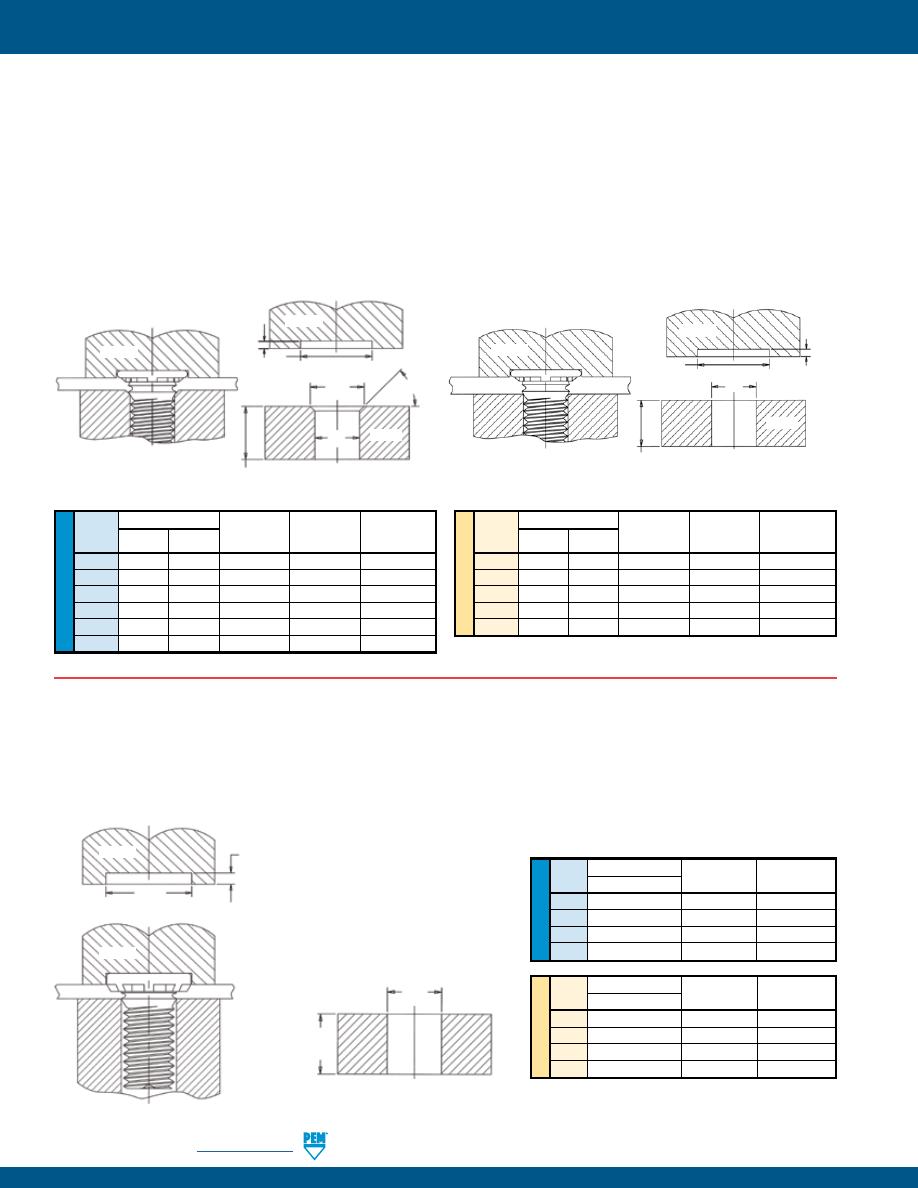
FH-20
PennEngineering •
www.pemnet.com
SELF-CLINCHING STUDS AND PINS
INSTALLATION - HFH™/HFHB™/HFHS™ STUDS
1.
Prepare properly sized mounting hole in sheet. Do not perform any secondary operations such as deburring.
2.
Insert stud through mounting hole (punch side) of sheet and into anvil hole.
3.
With punch and anvil surfaces parallel, apply squeezing force on the punch sufficient only to embed the ribs on the head of the stud
into the sheet. The standard punch design provides clearance for the stud head and reduces chances of over squeezing.
H
+.015” / +0.4 mm
+.025” / +0.6 mm
PUNCH
PUNCH
SHEET
.
035” - .036” (032)
.045” - .046” (0420)
.063” - .064” (0518)
.077” - .078” (0616)
0.94 mm - 0.96 mm (M5)
1.14 mm - 1.16 mm (M6)
1.62 mm - 1.64 mm (M8)
2.1 mm - 2.12 mm (M10)
U
NIF
IE
D
Thread Anvil Dimensions (in.)
Anvil Part
Punch Part
Code C
Number Number
032
.191 – .194
970200009300
970200311400
0420
.250 – .253
970200010300
970200312400
0518
.3125 – .3155
970200011300
970200313400
0616
.375 – .378
970200004300
970200314400
ME
T
RIC
Thread Anvil Dimensions (mm)
Anvil Part
Punch Part
Code
C +0.08
Number Number
M5
5.03
970200020300 970200311400
M6
6.03
970200230300 970200312400
M8
8.03
970200231300 970200313400
M10
10.03
970200402300 970200491400
INSTALLATION - TFH™/TFHS™ NON-FLUSH STUDS
1.
Prepare properly sized mounting hole in sheet. Do not perform any secondary operations such as deburring.
2.
Insert stud through mounting hole (punch side) of sheet and into anvil hole.
3.
With punch and anvil surfaces parallel, apply squeezing force until the punch contacts the sheet. When installed, the stud head is not
flush but will protrude approximately .025” / 0.64 mm. For sheets .030” / 0.76 mm and thicker, the anvil requires only a straight thru
hole to accommodate the stud. For sheets less than .030” / 0.76 mm down to .020” / 0.51 mm, the hole requires a countersink with
dimension A at the top to provide for metal flow around the shank of the stud. The standard punch design below provides clearance
for the stud head and reduces chances of over squeezing the head of the stud into the sheet metal.
Tooling for sheet thicknesses less than .030” / 0.76 mm down to
.020” / 0.51 mm.
Tooling for sheet thicknesses .030” / 0.76 mm and greater.
C
ANVIL
L +.125”/
3.18 mm Min.
U
NIF
IE
D
ME
T
RIC
Thread Anvil Dimensions (in.)
Anvil Part No.
Anvil Part No.
Punch
Code A C For Sheets
For Sheets
Part
> .030”
.020” - .029”
Number
256
.110-.114 .087-.090 970200005300 970200240300 970200235400
440 .136-.140 .113-.116 970200006300 970200241300 970200236400
632 .162-.166 .139-.142 970200007300 970200243300 970200237400
832 .188-.192 .165-.168 970200008300 970200245300 970200238400
032 .216-.220 .191-.194 970200009300 970200246300 970200239400
0420 .295-.300 .250-.253 970200010300 970200249300 970200496400
Thread Anvil Dimensions (mm)
Anvil Part No.
Anvil Part No.
Punch
Code
A + 0.1
C + 0.08
For Sheets
For Sheets
Part
> 0.76 mm
0.51 - 0.75 mm Number
M3
3.6
3.03 970200229300 970200242300 970200236400
M3.5
4.1
3.53 970200007300 970200243300 970200237400
M4
4.6
4.03 970200019300 970200244300 970200238400
M5
5.6
5.03 970200020300 970200247300 970200239400
M6
6.6
6.03 970200230300 970200248300 970200496400
PUNCH
PUNCH
ANVIL
A
C
H
+.015” / +0.4 mm
+.025” / +0.6 mm
SHEET
L +.125”/ 3.18 mm Min.
45° Nom.
.020” / 0.51 mm
.021” / 0.53 mm
PUNCH
PUNCH
ANVIL
C
H
+.015” / +0.4 mm
+.025” / +0.6 mm
.020” / 0.51 mm
.021” / 0.53 mm
SHEET
L +.125”/ 3.18 mm Min.
See page 8 for “L”.
See page 9 for “L”.
PEMSERTER® Installation Tooling
PEMSERTER® Installation Tooling
pem-html.html
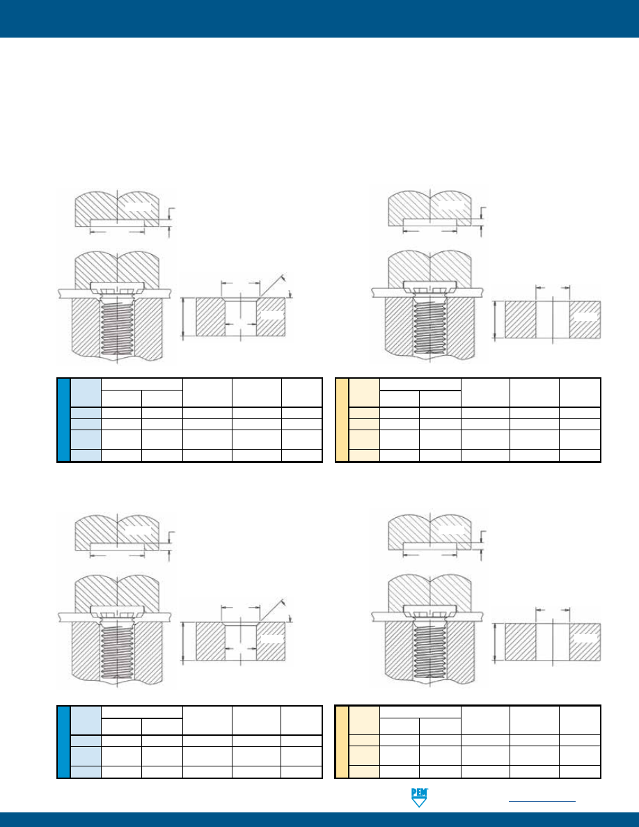
PennEngineering •
www.pemnet.com
FH-21
SELF-CLINCHING STUDS AND PINS
INSTALLATION - HFE™/THFE™/HFLH™ STUDS
HFE™/HFLH™ STUDS
1.
Prepare properly sized mounting hole in sheet. Do not perform any secondary operations such as deburring.
2.
Insert stud through mounting hole (punch side) of sheet and into anvil hole.
3.
With punch and anvil surfaces parallel, apply squeezing force on the punch sufficient only to embed the ribs on the head of the stud into
the sheet.
Tooling for sheet thicknesses less than .060” / 1.51 mm with #10 / M5
and 1/4” / M6 thread sizes and less than .075” / 1.9 mm with 5/16” /
M8 threads.
Tooling for sheet thicknesses .060” / 1.51 mm and greater with #10 /
M5 and 1/4” / M6 thread sizes and .075” / 1.9 mm and greater with
5/16” / M8 threads.
SHEET
.043” - .044” (032)
.055” - .056” (0420)
.078” - .079” (0518)
1.17 mm - 1.19 mm (M5)
1.39 mm - 1.42 mm (M6)
2 mm - 2.03 mm (M8)
H
+.015” / +0.4 mm
+.025” / +0.6 mm
PUNCH
A
C
45° Nom.
L +.125”/
3.18 mm Min.
ANVIL
SHEET
H
+.015” / +0.4 mm
+.025” / +0.6 mm
PUNCH
.043” - .044” (032)
.055” - .056” (0420)
.078” - .079” (0518)
1.17 mm - 1.19 mm (M5)
1.39 mm - 1.42 mm (M6)
2 mm - 2.03 mm (M8)
C
ANVIL
L +.125”/
3.18 mm Min.
PEMSERTER® Installation Tooling
Tooling for sheet thicknesses less than .052” / 1.31 mm with 1/4” / M6
thread sizes, and less than .067” / 1.71 mm with 5/16” / M8 thread sizes.
Tooling for sheet thicknesses .052” / 1.31 mm and greater with 1/4” / M6 and
.067” / 1.71 mm thread sizes and greater with 5/16” / M8 threads.
U
NIF
IE
D
ME
T
RIC
Thread Anvil Dimensions (in.)
Anvil Part No.
Anvil Part No.
Punch
Code A C For Sheets
For Sheets
Part
> .051”
.031” - .051” Number
0420 .302-.306 .250-.253
970200010300
8019886
8019890
For Sheets
For Sheets
> .066”
.031” - .066”
0518
.374-.378 .3125-.3155 970200011300
8019887
8019891
Thread Anvil Dimensions (mm)
Anvil Part No.
Anvil Part No.
Punch
Code
A + 0.1
C + 0.08
For Sheets
For Sheets
Part
> 1.3 mm
0.8 - 1.3 mm
Number
M6
7.25
6.03
970200230300 8019888
8019892
For Sheets
For Sheets
> 1.7 mm
0.8 - 1.7 mm
M8
9.55
8.03
970200231300 8019889
8019893
See page 10 for “L”.
SHEET
.064” - .065” (0420)
.094” - .095” (0518)
1.57 mm - 1.6 mm (M6)
2.41 mm - 2.44 mm (M8)
H
+.015” / +0.4 mm
+.025” / +0.6 mm
PUNCH
A
C
45° Nom.
L +.125”/
3.18 mm Min.
ANVIL
SHEET
H
+.015” / +0.4 mm
+.025” / +0.6 mm
PUNCH
.020” / 0.51 mm
.021” / 0.53 mm
C
ANVIL
L +.125”/
3.18 mm Min.
THFE™ STUDS
Type HFE see page 10 for “L”.
Type HFLH see page 12 for “L”.
PEMSERTER® Installation Tooling
U
NIF
IE
D
ME
T
RIC
Thread Anvil Dimensions (in.)
Anvil Part No.
Anvil Part No.
Punch
Code A C For Sheets
For Sheets
Part
> .060”
.040” - .060” Number
032
.216-.220
.191-.194 970200009300 970200246300 8003707
0420 .295-.300 .250-.253
970200010300
8003702
8003708
For Sheets
For Sheets
> .075”
.060” - .075”
0518 .334-.338 .3125-.3155 970200011300
8003703
8003709
Thread Anvil Dimensions (mm)
Anvil Part No.
Anvil Part No.
Punch
Code
A + 0.1
C + 0.08
For Sheets
For Sheets
Part
> 1.51 mm
1 mm - 1.51 mm
Number
M5
5.6
5.03
970200020300 8003704
8003710
M6
6.6
6.03
970200230300 8003705
8003711
For Sheets
For Sheets
> 1.9 mm
1.5 - 1.9 mm
M8
8.6
8.03
970200231300 8003706
8003712
pem-html.html
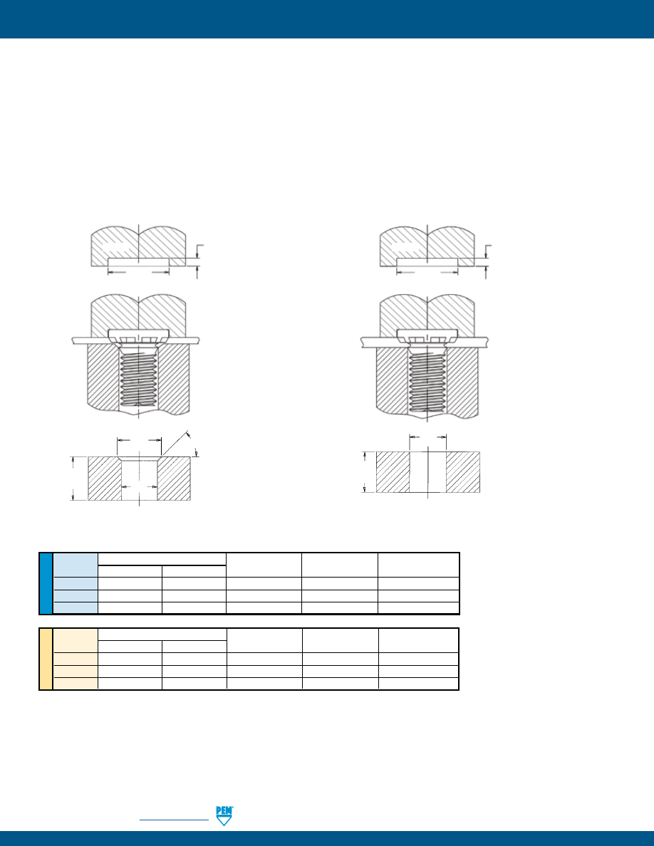
FH-22
PennEngineering •
www.pemnet.com
SELF-CLINCHING STUDS AND PINS
Tooling for sheet thicknesses less than .060” / 1.51 mm
with #10 / M5 and 1/4” / M6 thread sizes and less than
.075” / 1.9 mm with 5/16” / M8 threads.
Tooling for sheet thicknesses .060” / 1.51 mm and greater
with #10 / M5 and 1/4” / M6 thread sizes and .075” / 1.9
mm and greater with 5/16” / M8 threads.
SHEET
.072” - .073” (032)
.085” - .086” (0420)
.121” - .122” (0518)
1.93 mm - 1.95 mm (M5)
2.16 mm - 2.18 mm (M6)
3.12 mm - 3.14 mm (M8)
H
+.015” / +0.4 mm
+.025” / +0.6 mm
PUNCH
U
NIF
IE
D
Thread
Anvil Dimensions (in.)
Anvil Part Number
Anvil Part Number
Punch Part
Code
A C
(Standard Sheet)
(Thin Sheet)
Number
032
.216 – .220
.191 – .194
970200009300
970200246300
8014456
0420
.273 – .278
.250 – .253
8021609
8021613
8014458
0518
.334 – .338
.3125 – .3155
8021610
8021614
8014460
ME
T
RIC
Thread
Anvil Dimensions (mm)
Anvil Part Number
Anvil Part Number
Punch Part
Code
A +0.1
C +0.08
(Standard Sheet)
(Thin Sheet)
Number
M5
5.6 5.03
970200020300
8003704
8014457
M6
6.6
6.03
8021611
8021615
8014459
M8
8.6
8.03
8021612
8021616
8014461
C
ANVIL
L +.125”/
3.18 mm
Min.
SHEET
H
+.015” / +0.4 mm
+.025” / +0.6 mm
PUNCH
.072” - .073” (032)
.085” - .086” (0420)
.121” - .122” (0518)
1.93 mm - 1.95 mm (M5)
2.16 mm - 2.18 mm (M6)
3.12 mm - 3.14 mm (M8)
A
C
ANVIL
45° Nom.
L +.125”/
3.18 mm
Min.
INSTALLATION - HFG8™/HF109™ STUDS
1.
Prepare properly sized mounting hole in sheet. Do not perform any secondary operations such as deburring.
2.
Insert stud through mounting hole (punch side) of sheet and into anvil hole.
3.
With punch and anvil surfaces parallel, apply squeezing force on the punch sufficient only to embed the ribs on the head of the stud
into the sheet. Note that for sheets .060” / 1.51 mm and thicker, the anvil requires only a straight thru hole to accommodate the stud. For
sheets less than .060” / 1.51 mm to less than .075” / 1.9 mm, the hole requires a countersink with dimension A at the top to provide for
metal flow around the shank of the stud.
See page 11 for “L”.
PEMSERTER® Installation Tooling
pem-html.html
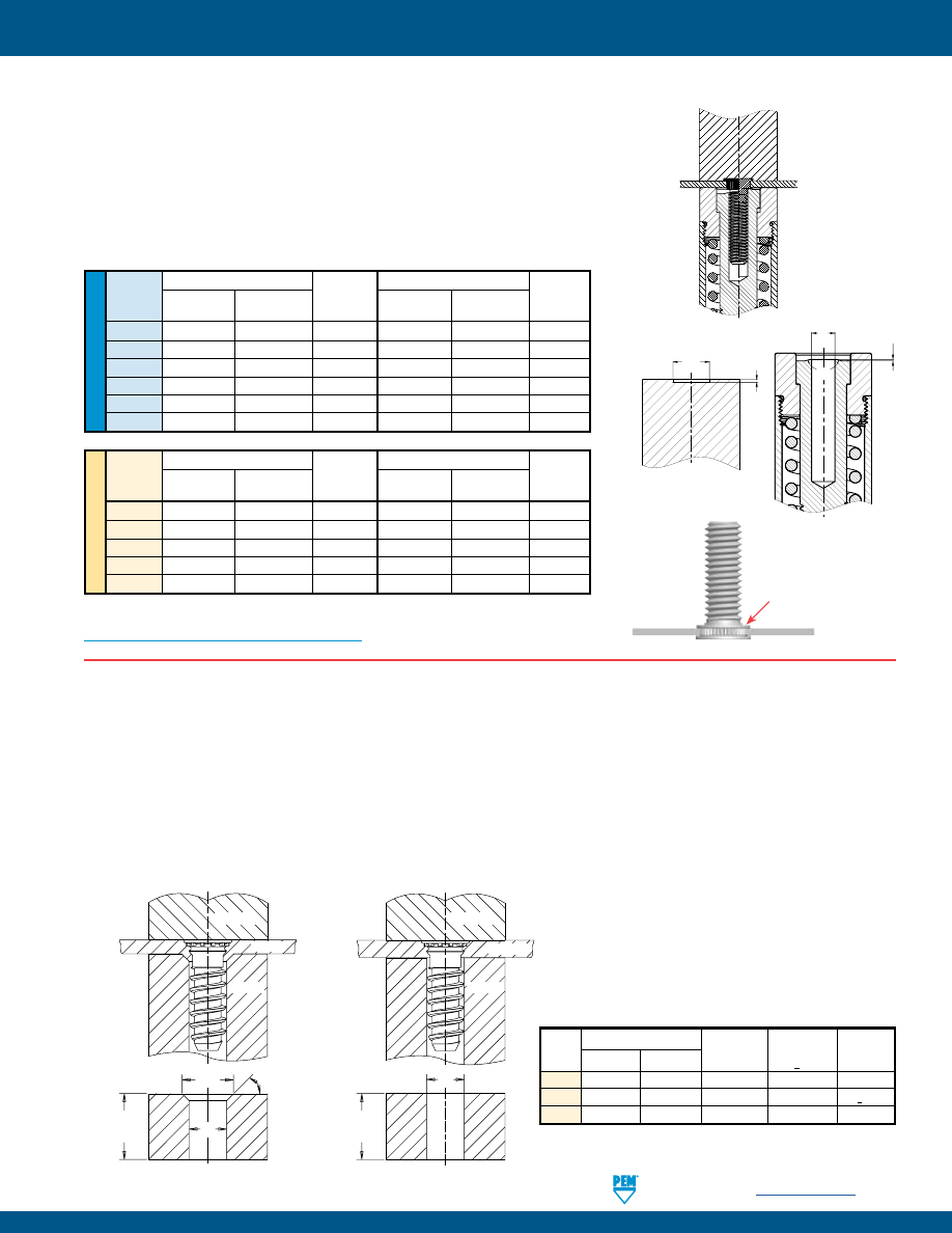
PennEngineering •
www.pemnet.com
FH-23
SELF-CLINCHING STUDS AND PINS
U
NIF
IE
D
Thread
Punch Dimensions (in.)
Punch Anvil Dimensions (in.) Anvil
Code
A
B
Part C P Part
+.004 –.000
+.000 –.001
Number
+.001
+.000 –.002
Number
256 .209 .019 8015111 .087 .014 8016983
440
.248
.022
8015112
.113
.014
8016984
632
.276
.022
8015113
.139
.014
8016985
832
.299
.022
8015114
.165
.014
8016986
032
.327
.022
8015115
.191
.014
8016987
0420
.386
.026
8015116
.251
.014
8016988
ME
TR
IC
Thread
Punch Dimensions (mm)
Punch Anvil Dimensions (mm) Anvil
Code
A
B
Part C P Part
+0.1
–0.025
Number +0.025
–0.05
Number
M2.5 5.5 0.47 8015117 2.53 0.35 8016989
M3
6.5
0.57
8015118
3.03
0.35
8016990
M4
7.5
0.57
8015119
4.03
0.35
8016991
M5
8.5
0.57
8015120
5.03
0.35
8016992
M6
9.5
0.67
8015121
6.03
0.35
8016993
Punch pushes over
protruding knurls
3.
NOTE:
For panel design information, go to
http://www.pemnet.com/SGPC_Panel_Designs.pdf
PUNCH
ANVIL
SHEET(S)
BEFORE
AFTER
1.
2.
A
B
PUNCH
ANVIL
C
P
150˚
INSTALLATION - SGPC™ SWAGING COLLAR STUDS
1.
Prepare properly sized mounting hole in sheet.
2.
Insert fastener through mounting hole (punch side) as shown in drawing.
3.
With installation punch and anvil surfaces parallel, apply squeezing force until the
punch pushes over the protruding knurls of the stud.
PEMSERTER® Installation Tooling
INSTALLATION - FHX™ STUDS
1.
Prepare properly sized mounting hole in sheet. Do not perform any secondary operations such as deburring.
2.
Insert stud through mounting hole (punch side) of sheet and into anvil hole.
3.
With punch and anvil surfaces parallel, apply squeezing force to embed the head of the stud flush in the sheet. In most cases, when
using sheets 1.51 mm and thicker, the anvil requires only a straight thru hole to accommodate the stud (see illustrations below for
details). For sheets less than 1.51 mm, the hole requires a countersink with dimension A at the top to provide for metal flow around
the shank of the stud.
Tooling for sheet thicknesses less
than 1.51 mm with 5 mm thread size
and less than 2.4 mm for 6 mm
thread size.
Tooling for sheet thicknesses 1.51 mm
and greater with 5 mm thread size
and 2.4 mm and greater for 6 mm
thread size.
PUNCH
ANVIL
SHEET
A
C
L +3.18 mm
Min.
45˚ Nom.
PUNCH
ANVIL
SHEET
C
L +3.18 mm
Min.
PEMSERTER® Installation Tooling
Anvil Dimensions (mm)
Anvil Part No.
Anvil Part No.
Punch
Thread
For Sheets
For Sheets
Part
Code
A C
< 1.51
> 1.51
Number
X5
6.12 - 6.22 5.23 - 5.31
8021189
8021188 975200048
< 2.4
> 2.4
X6
7.04 - 7.14 6.25 - 6.33
8021191
8021190
975200048
See page 14 for “L”.
pem-html.html
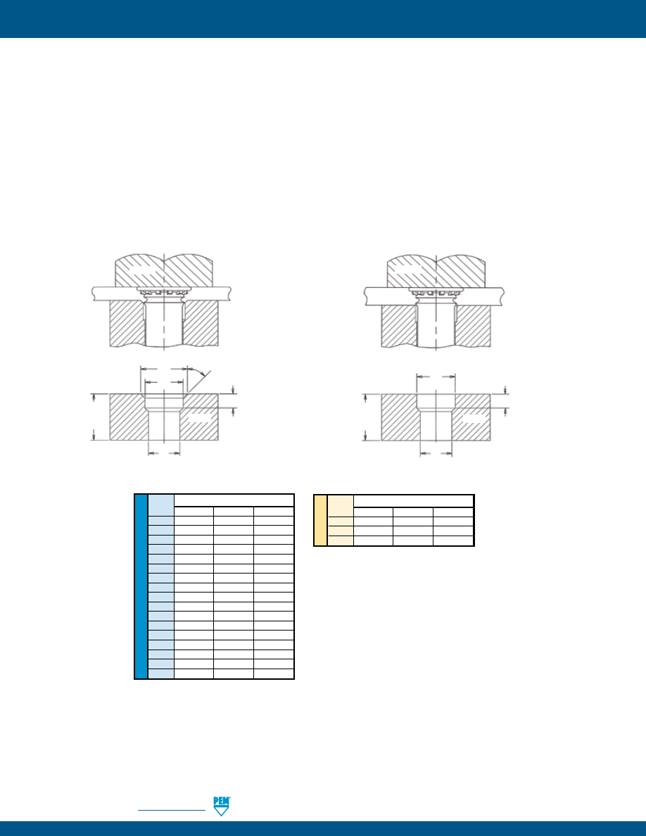
FH-24
PennEngineering •
www.pemnet.com
SELF-CLINCHING STUDS AND PINS
Tooling for sheet thicknesses less than .060” /
1.52 mm with 073 thru 173 / 3 mm thru 5 mm
pin diameter codes and for sheet thicknesses
less than .093 / 2.36 mm with 207 thru 223 pin
diameter codes.
Tooling for sheet thicknesses greater than .060”
/ 1.52 mm with 073 thru 173 / 3 mm thru 5 mm
pin diameter codes and for sheet thicknesses
greater than .093” / 2.36 mm with 207 thru 281
pin diameter codes.
U
NIF
IE
D
Pin Dia.
Anvil Dimensions (in.)
Code
A
+.004 –.000
B
±.002
C
±.002
073
.116
.089
.078
084
.133
.103
.089
094
.162
.115
.099
103
.166
.122
.109
106
.168
.129
.111
116
.191
.141
.121
120
.191
.141
.125
137
.215
.161
.144
141
.216
.167
.147
160
.244
.193
.166
167
.244
.193
.172
173
.250
.201
.180
207
.286
.240
.213
215
.290
.254
.221
223
.298
.254
.228
273
.325
.316
.277
281
.320
.316
.290
ME
T
RIC
Pin Dia.
Anvil Dimensions (mm)
Code
A
+0.1
B
±0.05
C
±0.05
3MM
4.9
3.61
3.1
4MM
5.44
4.19
4.1
5MM
6.93
5.61
5.1
A
C
SHEET
PUNCH
ANVIL
B
3/32”/
2.38 mm
Min.
L +.125”/
3.18 mm
Min.
45° Nom.
C
SHEET
PUNCH
ANVIL
B
3/32”/
2.38 mm
Min.
L +.125”/
3.18 mm
Min.
See page 15 for “L”.
INSTALLATION - FH™/FHS™/FHA™ PINS
1.
Prepare properly sized mounting hole in sheet. Do not perform any secondary operations such as deburring.
2.
Insert pin through mounting hole (punch side) of sheet and into anvil hole.
3.
With punch and anvil surfaces parallel, apply squeezing force to embed the head of the pin flush in the sheet. In most cases, when
using sheets .060” / 1.51 mm and thicker, the anvil requires only a straight thru hole to accommodate the pin (see illustrations
below for details). For sheets less than .060” / 1.51 mm, the hole requires a countersink with dimension A at the top to provide for
metal flow around the shank of the pin.
PEMSERTER® Installation Tooling
pem-html.html
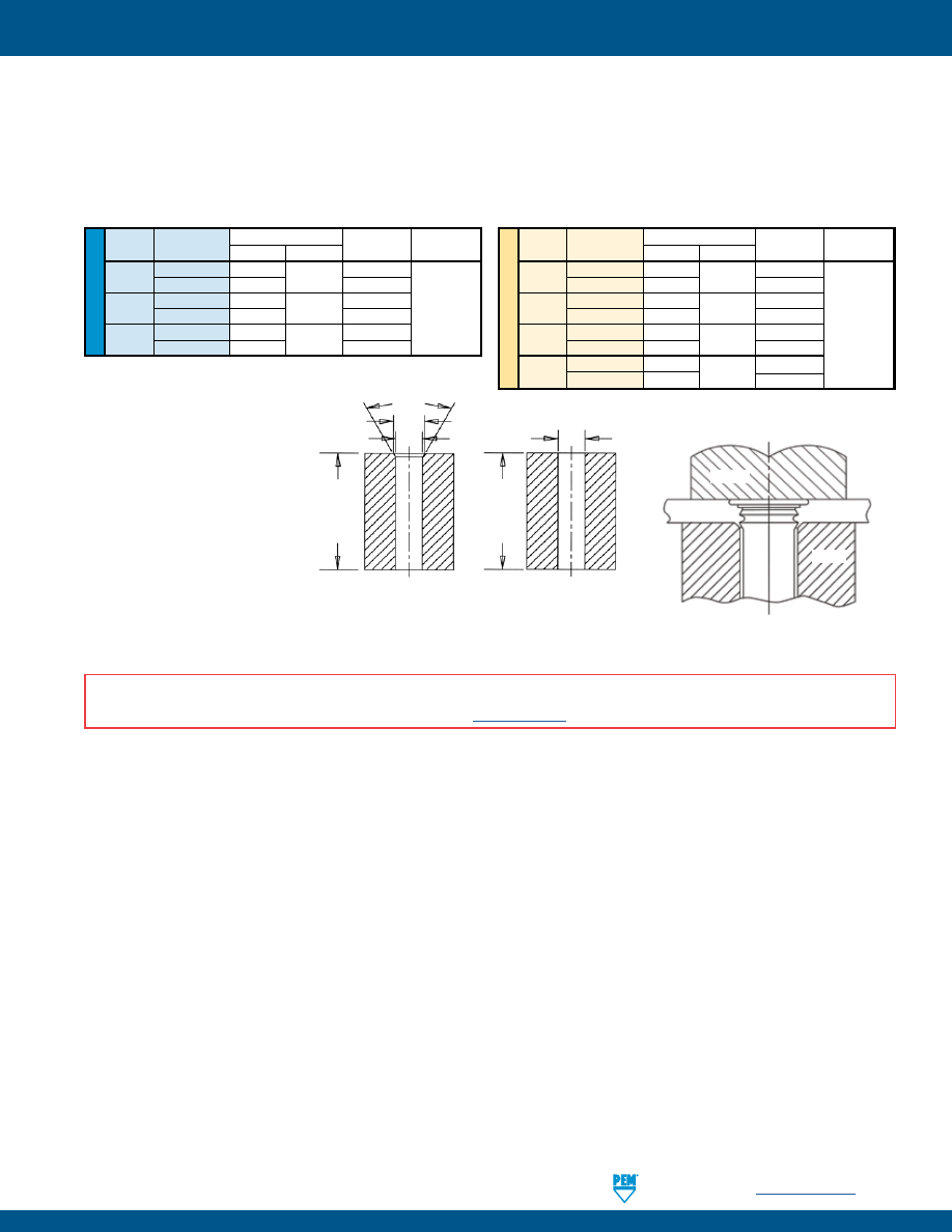
PennEngineering •
www.pemnet.com
FH-25
SELF-CLINCHING STUDS AND PINS
INSTALLATION - TPS™/TP4™/TPXS™ PILOT PINS
1.
Prepare properly sized mounting hole in sheet. Do not perform any secondary operations such as deburring.
2.
Insert pin through mounting hole (punch side) of sheet and into anvil hole.
3.
With punch and anvil surfaces parallel, apply squeezing force to embed the head of the pin flush in the sheet.
PUNCH
SHEET
ANVIL
(1) Chamfered anvil not required.
60°
Nom.
A
C
C
Recommended tooling
when a chamfered
anvil is required.
Recommended tooling
when a chamfered anvil
is not required.
L +.125”/
3.18 mm
Min.
L +.125”/
3.18 mm
Min.
See page 16 for “L”.
U
NIF
IE
D
Pin Dia.
Test Sheet Anvil Dimensions (in.)
Anvil Part
Punch Part
Code
Thickness (in.)
A ±.002
C ±.002
Number Number
125
.040 - .060
.160
.130
8003284
Over .060
(1)
8003278
187
.040 - .065
.220
.192
8003285
975200048
Over .065
(1)
8003279
250
.040 - .075
.285
.255
8003286
Over .075
(1)
8003280
ME
TR
IC
Pin Dia.
Test Sheet Anvil Dimensions (mm)
Anvil Part
Punch Part
Code
Thickness (mm)
A ±0.05
C ±0.05
Number Number
3MM
1 - 1.7
3.88
3.11
8008096
Over 1.7
(1)
8008095
4MM
1 - 1.7
4.88
4.11
8003287
Over 1.7
(1)
8003281
975200048
5MM
1 - 1.8
5.89
5.13
8003288
Over 1.8
(1)
8003282
6MM
1 - 1.9
6.89
6.12
8003289
Over 1.9
(1)
8003283
PEMSERTER® Installation Tooling
INSTALLATION NOTES
•
For best results we recommend using a PEMSERTER® press for installation of PEM self-clinching fasteners. Please check our website for more information.
•
Visit the Animation Library on our website to view the installation process
for select products
.
pem-html.html
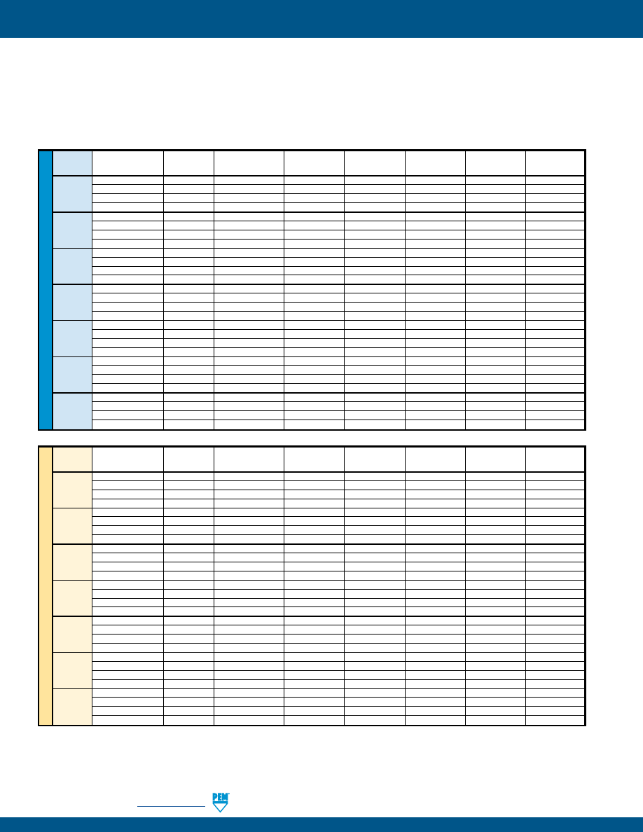
FH-26
PennEngineering •
www.pemnet.com
SELF-CLINCHING STUDS AND PINS
PERFORMANCE DATA - FH™/FHS™ FLUSH-HEAD STUDS
U
NIF
IE
D
Thread
Rec. Nut Tightening
Test Sheet
Sheet
Installation
Pushout
Torque-out
Pull Thru
Code
Torque (in. lbs.) (1)
Type
Thickness & Material
Hardness HRB
(lbs.)
(lbs.)
(in. lbs.)
(lbs.)
4.4
FH
.062” Aluminum
29
2000
100
5
425
256
2.7
FHS
.062” Aluminum
29
2000
100
4.5
300
4.4
FH
.060” Steel
59
2500
180
5
425
2.7
FHS
.060” Steel
59
2500
180
4.5
300
8.7
FH
.064” Aluminum
29
3800
170
10
650
440
5.9
FHS
.064” Aluminum
29
3200
170
8
500
8.7
FH
.060” Steel
59
4300
275
10
650
5.9
FHS
.060” Steel
59
4700
275
8
500
14
FH
.064” Aluminum
29
3800
180
17
850
632
11
FHS
.064” Aluminum
29
3500
180
16
775
14
FH
.060” Steel
59
4700
300
20
850
11
FHS
.060” Steel
59
5000
300
16
775
20
FH
.064” Aluminum
29
4800
220
28
1000
832
16
FHS
.064” Aluminum
29
4500
220
28
940
25
FH
.060” Steel
59
6800
375
40
1270
19
FHS
.060” Steel
59
5500
375
28
1130
28
FH
.064” Aluminum
29
5500
270
30
1220
032/024
24
FHS
.064” Aluminum
29
5500
270
30
1220
32
FH
.060” Steel
59
7500
450
60
1410
28
FHS
.060” Steel
59
6800
450
50
1410
69
FH
.093” Aluminum
28
6500
310
65
2300
0420
55
FHS
.093” Aluminum
28
6500
310
65
2100
77
FH
.088” Steel
46
9500
575
100
2550
67
FHS
.088” Steel
46
10000
575
100
2550
85
FH
.093” Aluminum
28
6500
430
100
2260
0518
74
FHS
.093” Aluminum
28
6700
430
100
2260
130
FH
.093” Steel
46
10000
650
175
3475
102
FHS
.093” Steel
46
11200
650
175
3120
ME
T
RIC
Thread
Rec. Nut Tightening
Test Sheet
Sheet
Installation
Pushout
Torque-out
Pull Thru
Code
Torque (N•m) (1)
Type
Thickness & Material
Hardness HRB
(kN)
(N)
(N•m)
(N)
0.78
FH
1.6 mm Aluminum
29
8.9
465
1.0
2600
M2.5
0.48
FHS
1.6 mm Aluminum
29
11.6
465
0.8
1820
0.84
FH
1.5 mm Steel
59
11.1
740
1.0
2800
0.55
FHS
1.5 mm Steel
59
13.8
740
0.8
1820
1.1
FH
1.6 mm Aluminum
29
12.9
600
1.7
3150
M3
0.81
FHS
1.6 mm Aluminum
29
12.9
600
1.3
2570
1.4
FH
1.5 mm Steel
59
14.7
820
1.7
3840
0.88
FHS
1.5 mm Steel
59
14.7
820
1.3
2440
1.6
FH
1.6 mm Aluminum
29
15.6
800
1.7
3780
M3.5
1.3
FHS
1.6 mm Aluminum
29
15.6
800
1.7
3445
1.6
FH
1.5 mm Steel
59
22.3
1335
2.8
3780
1.4
FHS
1.5 mm Steel
59
22.3
1335
2.0
3445
2.1
FH
1.6 mm Aluminum
29
20
975
2.9
4448
M4
1.8
FHS
1.6 mm Aluminum
29
22.3
975
2.9
4180
2.7
FH
1.5 mm Steel
59
28.9
1780
4.2
5650
2.3
FHS
1.5 mm Steel
59
26.7
1780
2.9
4775
3.1
FH
1.6 mm Aluminum
29
24.5
1070
3.5
5170
M5
2.5
FHS
1.6 mm Aluminum
29
24.5
1070
3.5
4760
3.8
FH
1.5 mm Steel
59
33.4
2000
6.5
6270
3.6
FHS
1.5 mm Steel
59
32.5
2000
6.3
6000
7.3
FH
2.4 mm Aluminum
28
28.9
1660
7.3
10200
M6
5.7
FHS
2.4 mm Aluminum
28
28.9
1660
7.3
9090
8.1
FH
2.2 mm Steel
46
44.5
2560
11.3
11300
7.6
FHS
2.2 mm Steel
46
44.5
2560
10.1
10600
10
FH
2.4 mm Aluminum
28
29.8
1910
11.3
10500
M8
8
FHS
2.4 mm Aluminum
28
29.8
1910
11.3
9540
15
FH
2.4 mm Steel
46
44.5
2890
19.2
15450
13
FHS
2.4 mm Steel
46
49.8
2890
17.5
13630
Published installation forces are for general reference. Actual set-up and confirmation of complete installation should be made by observing
proper seating of fastener as described in the installation steps. Other performance values reported are averages when all proper installation
parameters and procedures are followed. Variations in mounting hole size, sheet material, and installation procedure may affect performance.
Performance testing this product in your application is recommended. We will be happy to provide technical assistance and/or samples for
this purpose.
(1) Tightening torque shown is a theoretical value calculated to induce a load of 75% of minimum axial yield strength of the stud with an assumed K value or
nut factor equal to 0.20. In some applications tightening torque may needed to be adjusted based on the actual K value.
pem-html.html
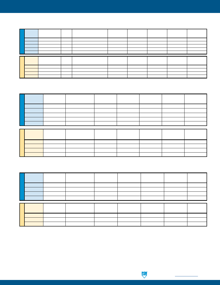
PennEngineering •
www.pemnet.com
FH-27
SELF-CLINCHING STUDS AND PINS
ME
T
RIC
U
NIF
IE
D
ME
T
RIC
U
NIF
IE
D
PERFORMANCE DATA - FH4™ STUDS
(2)
Rec. Nut
Test Sheet
Sheet
Thread
Tightening
Thickness and
Hardness
Installation
Pushout
Torque-out
Pull Thru
Code
Torque (in. lbs.)
(1)
Material
(3)
HRB (lbs.)
(lbs.) (in.
lbs.) (lbs.)
440
11
.060” Stainless Steel
87
9000
450
16
800
632
22
.060” Stainless Steel
87
9500
540
27
1350
832
35
.060” Stainless Steel
86
11200
780
58
1800
032
51
.060” Stainless Steel
86
12000
800
95
2250
0420
117
.062” Stainless Steel
88
23000
1600
156
3900
(1) Tightening torque shown is a theoretical value calculated to induce a load of 75% of minimum axial yield strength of the stud with an assumed K
value or nut factor equal to 0.20. In some applications tightening torque may needed to be adjusted based on the actual K value.
(2) Performance values shown are typical for fasteners properly installed using raised ring tooling in good condition. We recommend replacing
installation tooling when the height of the “P” falls out of tolerance (see page 18). Reductions in performance may occur as the height of the
protrusion wears. Variations in hole preparation, installation force, and sheet material type, thickness, and hardness will affect both performance and
tooling life.
(3) Performance may be reduced for studs installed into thicker sheets.
Rec. Nut
Test Sheet
Sheet
Thread
Tightening
Thickness and
Hardness
Installation
Pushout
Torque-out
Pull Thru
Code
Torque (N•m)
(1)
Material
(3)
HRB (kN)
(N) (N•m) (N)
M3
1.3
1.5 mm Stainless Steel
87
40
2220
1.8
3500
M4
3.8
1.5 mm Stainless Steel
86
50
3210
6.5
8000
M5
6
1.5 mm Stainless Steel
86
53
3560
10.7
10000
M6
11
1.6 mm Stainless Steel
88
71
4200
15.9
14900
PERFORMANCE DATA - FHP™ STUDS
(2)
Rec. Nut
Test Sheet
Sheet
Thread
Tightening
Thickness and
Hardness
Installation
Pushout
Torque-out
Pull Thru
Code
Torque (in. lbs.)
(1)
Material
(3)
HRB (lbs.)
(lbs.)
(in. lbs.)
(lbs.)
440
8.1
.045” Stainless Steel
86
9000
520
10.6
605
632
16
.045” Stainless Steel
86
9500
670
19.5
940
832
28
.045” Stainless Steel
86
11200
785
37.5
1415
032
34
.045” Stainless Steel
86
12000
800
59.5
1500
Rec. Nut
Test Sheet
Sheet
Thread
Tightening
Thickness and
Hardness
Installation
Pushout
Torque-out
Pull Thru
Code
Torque (N•m)
(1)
Material
(3)
HRB (kN)
(N) (N•m) (N)
M3
1.3
2 mm Stainless Steel
86
40
2500
1.6
3500
M4
2.9
1.14 mm Stainless Steel
86
50
3000
3.9
6000
M5
4.4
1.14 mm Stainless Steel
86
53
3560
7.35
7320
PERFORMANCE DATA - FHA™ FLUSH-HEAD STUDS
U
NIF
IE
D
Thread
Rec. Nut Tightening
Test Sheet
Sheet
Installation
Pushout
Torque-out
Pull Thru
Code
Torque (in. lbs.)
(1)
Type
Thickness & Material
Hardness HR15T
(lbs.)
(lbs.)
(in. lbs.)
(lbs.)
440
3.6
FHA
.061” 5052-H34 Aluminum
75
2500
155
4
270
632
6.3
FHA
.061” 5052-H34 Aluminum 75 2600 180 8 380
832
9.8
FHA
.061” 5052-H34 Aluminum 73 3200 190 15 500
032
14
FHA
.061” 5052-H34 Aluminum 75 3200 220 28 600
0420
32
FHA
.062” 5052-H34 Aluminum 75 5500 300 55 1050
ME
T
RIC
Thread
Rec. Nut Tightening
Test Sheet
Sheet
Installation
Pushout
Torque-out
Pull Thru
Code
Torque (N•m)
(1)
Type
Thickness & Material
Hardness HR15T
(kN)
(N)
(N•m)
(N)
M3
0.54
FHA
1.55 mm 5052-H34 Aluminum
74
10.7
575
0.5
1500
M4
0.96
FHA 1.55 mm 5052-H34 Aluminum 75
14.3 775 1.35 2000
M5
1.5
FHA 1.55 mm 5052-H34 Aluminum 75
15.2 900
2.6 2500
M6
3.2
FHA 1.6 mm 5052-H34 Aluminum 75 24.5 1500 5.3 4500
pem-html.html
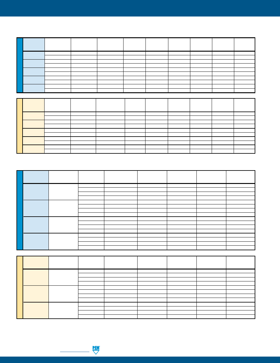
FH-28
PennEngineering •
www.pemnet.com
SELF-CLINCHING STUDS AND PINS
ME
T
RIC
U
NIF
IE
D
Max. Nut
Test Sheet
Sheet
Thread
Tightening
Type
Thickness and
Hardness
Installation
Pushout
Torque-out
Code
Torque (in. lbs.)
Material
HRB
(lbs.)
(2)
(lbs.)
(in. lbs.)
TFH
.020” Aluminum
28
1300
45
7
440 5
TFHS
.020” Aluminum
28
1200
45
7
TFH
.023” Steel
52
2800
100
8
TFHS
.025” Steel
52
1500
100
8
TFH
.020” Aluminum
28
2100
50
8
632 9
TFHS
.020” Aluminum
28
1500
50
8
TFH
.023” Steel
52
2500
110
16
TFHS
.025” Steel
52
2500
110
16
TFH
.020” Aluminum
28
2100
60
10
832 17
TFHS
.020” Aluminum
28
2200
60
11
TFH
.023” Steel
52
3100
120
26
TFHS
.025” Steel
52
2700
120
26
024 24
TFH
.020” Aluminum
28
2300
65
14
TFHS
.020” Aluminum
28
2500
65
14
032 27
TFH
.023” Steel
52
3700
150
30
TFHS
.025” Steel
52
3000
130
28
Max. Nut
Test Sheet
Sheet
Thread
Tightening
Type
Thickness and
Hardness
Installation Pushout Torque-out
Code
Torque (N•m)
Material
HRB
(kN)
(2)
(N) (N•m)
TFH
0.5 mm Aluminum
28
5.8
195
0.6
M3 0.74
TFHS
0.5 mm Aluminum
28
5.3
195
0.6
TFH
0.6 mm Steel
52
12.5
300
1
TFHS
0.6 mm Steel
52
6.7
300
1
TFH
0.5 mm Aluminum
28
12.5
250
0.7
M4 1.7
TFHS
0.5 mm Aluminum
28
9.8
250
0.7
TFH
0.6 mm Steel
52
17.8
500
2.5
TFHS
0.6 mm Steel
52
13.4
500
2.5
TFH
0.5 mm Aluminum
28
15.6
270
1.3
M5 3.5
TFHS
0.5 mm Aluminum
28
13.4
270
1.3
TFH
0.6 mm Steel
52
26.7
670
3
TFHS
0.6 mm Steel
52
17.8
670
3
PERFORMANCE DATA - TFH™/TFHS™ NON-FLUSH STUDS
(1) Tightening torque shown is a theoretical value calculated to induce a load of 75% of minimum axial yield strength of the stud with an assumed K value
or nut factor equal to 0.20. In some applications tightening torque may needed to be adjusted based on the actual K value.
(2) Installation controlled by proper cavity depth in punch.
PERFORMANCE DATA - FHL™/FHLS™ STUDS
ME
T
RIC
U
NIF
IE
D
Rec. Nut
Test Sheet
Sheet
Pull Thru
Thread
Tightening
Type
Thickness and
Hardness
Installation
Pushout
Torque-out
Pull Thru
Test Bushing
Code
Torque (in. lbs.)
(1)
Material
HRB
(lbs.)
(lbs.)
(in. lbs.)
(lbs.)
Hole Size (in.)
256
2.1
FHL / FHLS
.047” Aluminum
33
700
55
4
230
.106
3.8
FHL / FHLS
.045” Steel
54
1200
85
8
425
.106
440
3.5
FHL / FHLS
.047” Aluminum
33
1000
60
5
300
.132
6.8
FHL / FHLS
.045” Steel
54
1200
105
11
580
.132
632
4.7
FHL / FHLS
.047” Aluminum
33
1000
65
6.5
325
.158
9
FHL / FHLS
.045” Steel
54
1500
110
15
650
.158
832
6
FHL / FHLS
.047” Aluminum
33
1200
80
9
350
.184
13
FHL / FHLS
.045” Steel
54
1500
125
18
740
.184
032
7.9
FHL / FHLS
.047” Aluminum
33
2500
115
18
395
.210
16
FHL / FHLS
.045” Steel
54
4500
210
38
800
.210
Rec. Nut
Test Sheet
Sheet
Pull Thru
Thread
Tightening
Type
Thickness and
Hardness
Installation
Pushout
Torque-out
Pull Thru
Test Bushing
Code
Torque (N•m)
(1)
Material
HRB
(kN)
(N)
(N•m)
(N)
Hole Size (mm)
M2.5
0.32
FHL / FHLS
1.2 mm Aluminum
33
3.1
285
0.55
1200
3
0.59
FHL / FHLS
1.1 mm Steel
54
5.3
450
1.1
2250
3
M3
0.41
FHL / FHLS
1.2 mm Aluminum
33
4.4
285
0.65
1300
3.5
0.79
FHL / FHLS
1.1 mm Steel
54
5.3
475
1.25
2500
3.5
M3.5
0.51
FHL / FHLS
1.2 mm Aluminum
33
4.4
290
0.76
1400
4
1.03
FHL / FHLS
1.1 mm Steel
54
6.6
500
1.75
2800
4
M4
0.65
FHL / FHLS
1.2 mm Aluminum
33
5.3
365
1.1
1550
4.5
1.39
FHL / FHLS
1.1 mm Steel
54
6.6
550
2.1
3300
4.5
M5
0.97
FHL / FHLS
1.2 mm Aluminum
33
11.1
530
2.2
1850
5.5
1.97
FHL / FHLS
1.1 mm Steel
54
20
1000
4.4
3750
5.5
pem-html.html
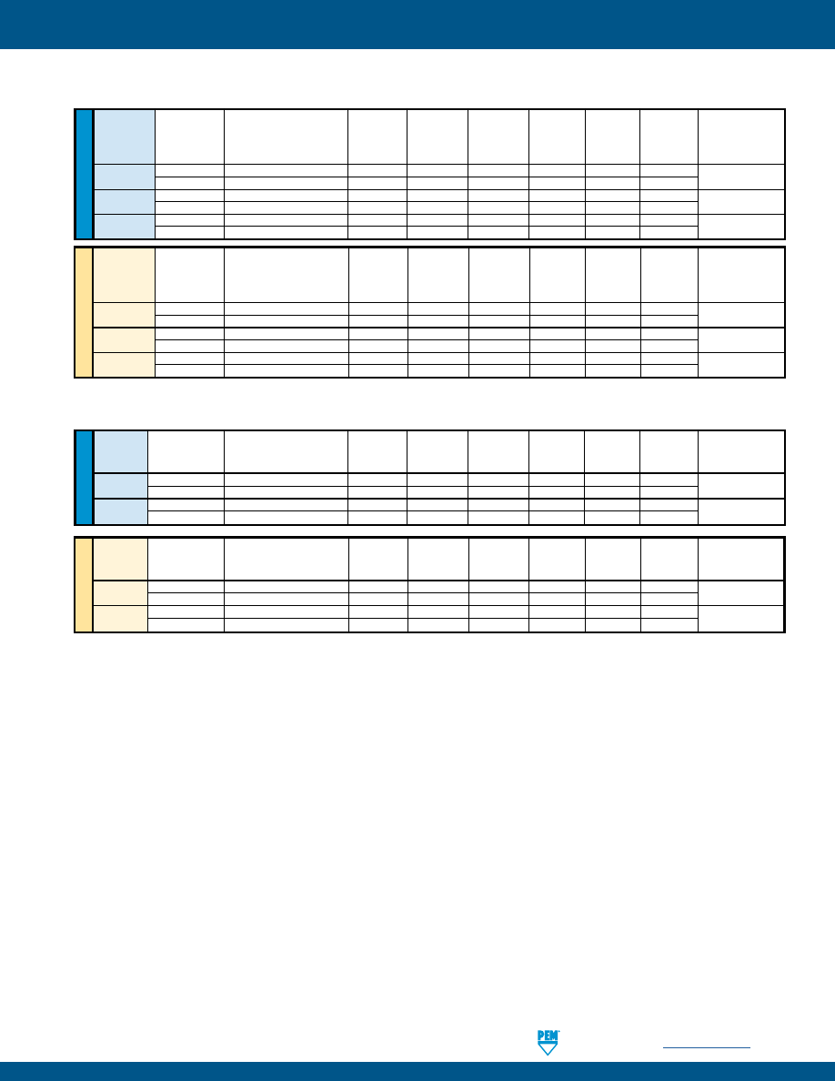
PennEngineering •
www.pemnet.com
FH-29
SELF-CLINCHING STUDS AND PINS
(1) Tightening torque shown is a theoretical value calculated to induce a load of 75% of minimum axial yield strength of the stud with an assumed K value
or nut factor equal to 0.20. In some applications tightening torque may needed to be adjusted based on the actual K value.
(2) Installation controlled by proper cavity depth in punch.
(3) Head size is adequate to ensure failure in threaded area.
ME
T
RIC
U
NIF
IE
D
Rec.
Nut
Thread
Tightening
Test Sheet Thickness
Sheet
Installation
Pushout
Torque-out
Tensile
Pull Thru
Test Bushing
Code
Torque
and Material
Hardness
(kN)
(2)
(N)
(N•m)
Strength
(kN)
Hole Size
(N•m)
(1)
(mm)
HRB
(kN)
(3)
For Pull Thru Tests
M5
5.8
1 mm Aluminum
27
37.7
690
8.1
12.8
9.7
7.4
6.4
1 mm Cold-rolled Steel
67
51.1
1350
8.1
12.8
10.6
M6
10
1 mm Aluminum
27
39
750
11.8
18.1
14.2
8.2
11
1 mm Cold-rolled Steel
67
60
1400
14.4
18.1
15.5
M8
24
1.5 mm Aluminum
22
42
1230
23.5
32.9
25
10.3
26
1.5 mm Cold-rolled Steel
65
71.1
2400
33.9
32.9
27.5
Rec.
Nut
Thread
Tightening
Test Sheet Thickness
Sheet
Installation
Pushout
Torque-out
Tensile
Pull Thru
Test Bushing
Code
Torque
and Material
Hardness
(lbs.)
(2)
(lbs.)
(in. lbs.)
Strength
(lbs.)
Hole Size
(ft. lbs.)
(1)
(in.)
HRB
(lbs.)
(3)
For Pull Thru Tests
032
3.6
.040” Aluminum
27
7500
170
60
2400
1900
.279
4.2
.040” Cold-rolled Steel
67
9500
300
60
2400
2200
0420
8
.040” Aluminum
27
8000
180
120
3820
3200
.335
9
.040” Cold-rolled Steel
67
13500
340
130
3820
3600
0518
19
.060” Aluminum
22
9000
275
240
6280
6000
.407
20
.060” Cold-rolled Steel
65
15500
575
290
6280
6400
PERFORMANCE DATA - HFE™ STUDS
PERFORMANCE DATA - THFE™ STUDS
ME
T
RIC
U
NIF
IE
D
Rec. Nut
Test Sheet Thickness
Sheet
Tensile
Test Bushing
Thread
Tightening Torque
and Material
Hardness
Installation
Pushout
Torque-out
Strength
Pull Thru
Hole Size
Code
(N•m)
(1)
(mm)
HRB (kN)
(2)
(N) (N•m) (kN)
(3)
(kN)
For Pull Thru Tests
M6
9
0.8 mm Aluminum
38
39.2
550
7.3
18.1
13
8.3
10
0.8 mm Cold-rolled Steel
47
60.1
886
13.4
18.1
14.3
M8
27
0.8 mm Aluminum
44
56
582
12.2
32.9
27.8
10.3
27
0.8 mm Cold-rolled Steel
47
71.2
881
13.1
32.9
28.1
Rec. Nut
Test Sheet Thickness
Sheet
Tensile
Test Bushing
Thread
Tightening Torque
and Material
Hardness
Installation
Pushout
Torque-out
Strength
Pull Thru
Hole Size
Code
(ft. lbs.)
(1)
(in.)
HRB (lbs.)
(2)
(lbs.)
(in. lbs.)
(lbs.)
(3)
(lbs.)
For Pull Thru Tests
0420
8.1
.031” Aluminum
35
8800
116
71
3820
3249
.340
8.5
.031” Cold-rolled Steel
47
13500
197
116
3820
3388
0518
18
.031” Aluminum
44
11700
131
103
6280
5701
.402
18
.031” Cold-rolled Steel
47
16000
187
124
6280
5772
pem-html.html
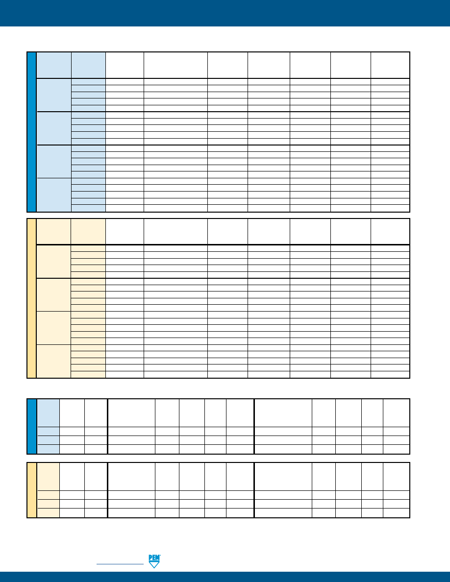
FH-30
PennEngineering •
www.pemnet.com
SELF-CLINCHING STUDS AND PINS
PERFORMANCE DATA - HFG8™/HF109™ HIGH TENSILE STRENGTH STUDS
U
NIF
IE
D
Rec. Nut
Tightening Tensile
Sheet
Sheet
Thread
Torque
Strength
Test Sheet
Hardness Installation Pushout Torque-out
Test Sheet
Hardness Installation Pushout Torque-out
Code
(ft. lbs.)
(lbs.)
(3)
Material
HRB (lbs.)
(2)
(lbs.)
(ft. lbs.)
Material
HRB
(lbs.)
(2)
(lbs.)
(ft. lbs.)
032
6.4
3000
.047” HSLA Steel
85.5
14000
483
6.2
.040” Cold-rolled Steel
45.0
9900
249
5.9
0420
13
4750
.047” HSLA Steel
85.7
21400
592
11.5
.040” Cold-rolled Steel
45.0
14100
248
11.5
0518
28
7850
.060” HSLA Steel
84.9
32600
667
25.6
.060” Cold-rolled Steel
55.2
19100
447
25.2
ME
T
RIC
Rec. Nut
Tightening Tensile
Sheet
Sheet
Thread
Torque
Strength
Test Sheet
Hardness Installation Pushout Torque-out
Test Sheet
Hardness Installation Pushout Torque-out
Code
(N•m) (kN)
(3)
Material
HRB (kN)
(2)
(N) (N•m)
Material
HRB (kN)
(2)
(N) (N•m)
M5
10
14.8
1.2 mm HSLA Steel
86.1
60.1
2084
9
1 mm Cold-rolled Steel
45.3
43.2
978
9
M6
17
20.9
1.2 mm HSLA Steel
85.6
90
2454
15.6
1 mm Cold-rolled Steel
45.5
60
1072
14.4
M8
41
38.1
1.5 mm HSLA Steel
84
145
3026
38.4
1.5 mm Cold-rolled Steel
55
85
1992
37.7
(1) Tightening torque shown is a theoretical value calculated to induce a load of 75% of minimum axial yield strength of the stud with an assumed K value
or nut factor equal to 0.20. In some applications tightening torque may needed to be adjusted based on the actual K value.
(2) Installation controlled by proper cavity depth in punch.
(3) Head size is adequate to ensure failure in threaded area.
ME
T
RIC
U
NIF
IE
D
Rec. Nut
Test Sheet
Sheet
Tensile
Thread
Type Tightening Thickness and
Hardness
Installation Pushout Torque-out Strength
Code
Torque
Material
HRB
(lbs.)
(2)
(lbs.)
(ft. lbs.)
(lbs.)
(ft. lbs.)
(1)
HFH
4.6
.060” Aluminum
15
3000
180
4
2400
HFH
4.6
.060” Steel
65
6000
375
5
2400
032
HFHS
2.5
.050” Aluminum
38
3000
180
4
1500
HFHS
2.5
.058” Steel
52
4500
325
4
1500
HFHB
1.7
.061” Copper CDA-110 28 3400 150 2.9 1200
HFH
9.6
.060” Aluminum
43
5500
285
11
3820
HFH
9.6
.060” Steel
59
7000
480
11
3820
0420
HFHS
5.2
.064” Aluminum
32
4000
285
8
2385
HFHS
5.2
.072” Steel
43
6500
480
8
2385
HFHB
3.6
.061” Copper CDA-110 28 6000 380 5 1908
HFH
20
.091” Aluminum
39
8000
380
22
6280
HFH
20
.090” Steel
58
10000
590
22
6280
0518
HFHS
11
.087” Aluminum
41
5500
380
15
3930
HFHS
11
.099” Steel
44
7500
590
15
3930
HFHB
7
.126” Copper CDA-110 32 7500 500 11 3140
HFH
35
.091” Aluminum
39
12000
550
25
9300
HFH
35
.090” Steel
58
16000
780
36
9300
0616
HFHS
19
.123” Aluminum
44
10000
560
25
5810
HFHS
19
.099” Steel
44
13000
780
25
5810
HFHB
13
.126” Copper CDA-110 32 12000 560 18 4650
PERFORMANCE DATA - HFH™/HFHS™/HFHB™ STUDS
Rec. Nut
Test Sheet
Sheet
Tensile
Thread
Type Tightening Thickness and
Hardness
Installation Pushout Torque-out Strength
Code
Torque
Material
HRB
(kN)
(2)
(N) (N•m) (kN)
(N•m)
(1)
HFH
7.7
1.5 mm Aluminum
15
13
800
5.4
12.8
HFH
7.7
1.5 mm Steel
65
26
1500
7.6
12.8
M5
HFHS
3.8
1.62 mm Aluminum
35
12.4
800
5.4
7.3
HFHS
3.8
1.47 mm Steel
54
21.7
1500
6.4
7.3
HFHB
2.7
1.5 mm Copper CDA-110 28
15.6 1115 3.4 5.9
HFH
13
1.5 mm Aluminum
43
29
1270
14
18.1
HFH
13
1.5 mm Steel
59
33
1750
14
18.1
M6
HFHS
6.5
1.62 mm Aluminum
35
15.4
1270
11
10.3
HFHS
6.5
1.6 mm Steel
45
24.6
1750
11
10.3
HFHB
4.5
1.5 mm Copper CDA-110 28 25.3 1600 6.7 8.3
HFH
32
2.3 mm Aluminum
39
35.6
1700
30
32.9
HFH
32
2.3 mm Steel
58
44.5
2200
30
32.9
M8
HFHS
16
2.23 mm Aluminum
44
24.4
1700
20
18.8
HFHS
16
2.48 mm Steel
43
37.8
2100
20
18.8
HFHB
11
3.2 mm Copper CDA-110 32
33 2250 15.3 15.1
HFH
63
2.3 mm Aluminum
39
53.3
2445
36
52.2
HFH
63
2.3 mm Steel
58
71.2
3470
49
52.2
M10
HFHS
31
2.3 mm Aluminum
44
44.4
2445
36
29.9
HFHS
31
2.3 mm Steel
44
57.7
3470
36
29.9
HFHB
22
3.2 mm Copper CDA-110 32
53.3 2500 25
24
pem-html.html
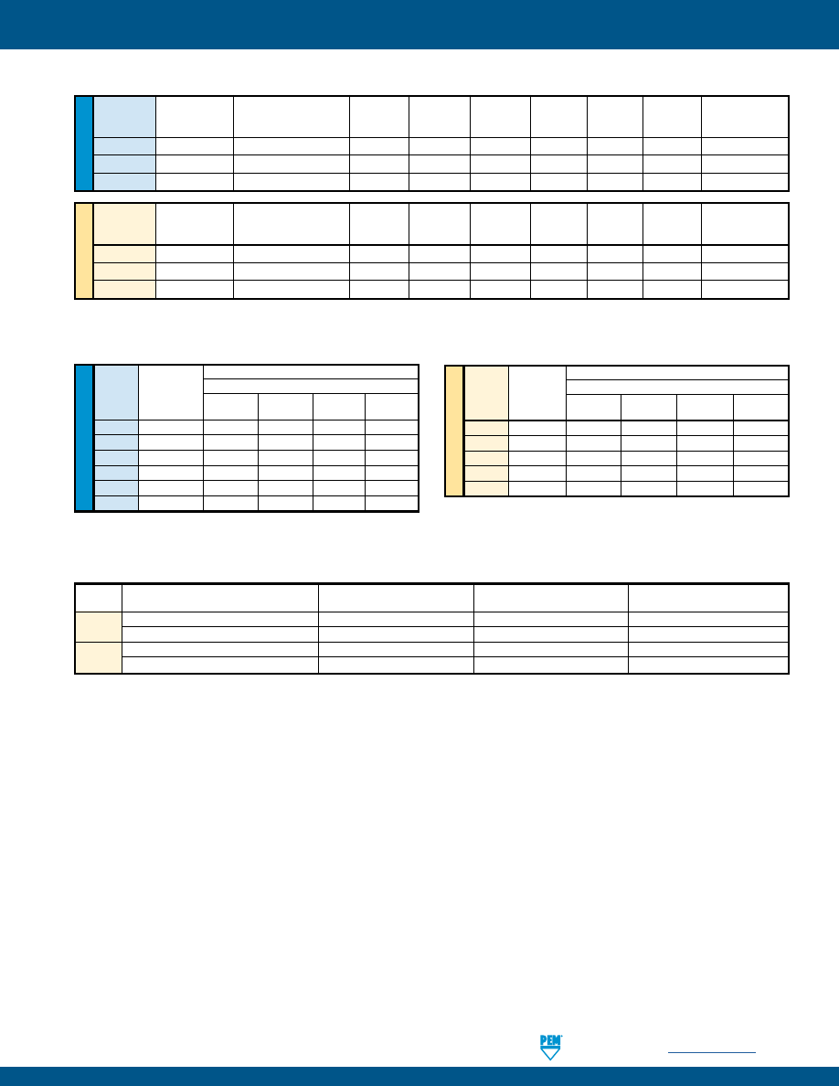
PennEngineering •
www.pemnet.com
FH-31
SELF-CLINCHING STUDS AND PINS
(1) Tightening torque shown is a theoretical value calculated to induce a load of 75% of minimum axial yield strength of the stud with an assumed K value
or nut factor equal to 0.20. In some applications tightening torque may needed to be adjusted based on the actual K value.
(2) Installation controlled by proper cavity depth in punch.
(3) Head size is adequate to ensure failure in threaded area when tested with industry standard tensile bushing diameter.
(4) HRB - Hardness Rockwell “B” Scale. HB - Hardness Brinell.
PERFORMANCE DATA - HFLH™ STUDS
U
NIF
IE
D
Test Sheet Material
Thread
Rec. Nut Single sheet of .039” 300 Series Stainless Steel
Code
Tightening
Torque Installation Pushout Torque-out Pull-thru
(in. lbs.)
(1)
(lbs.)
(lbs.)
(in. lbs.)
(lbs.)
256
3.7
4000
425
5.2
415
440
6
5000
450
8
512
632
12
5500
460
15.8
811
832
20
6500
480
29.3
1133
032
25
7300
545
42.8
1273
0420
45
10000
565
76.7
1721
ME
TR
IC
Test Sheet Material
Thread
Rec. Nut Single sheet of 1 mm 300 Series Stainless Steel
Code
Tightening
Torque Installation Pushout Torque-out Pull-thru
(N•m)
(1)
(kN) (N) (N•m) (N)
M2.5
0.67
20.1
2546
0.86
2561
M3
0.9
21.8
2051
1.35
2851
M4
2.5
28.5
2396
2.66
4000
M5
3.3
35.6
3200
5.96
4284
M6
3.3
42.3
3262
9.19
6311
PERFORMANCE DATA - SGPC™ SWAGING COLLAR STUDS
U
NIF
IE
D
Rec. Nut
Test Sheet Thickness
Sheet
Installation
Pushout Torque-out Tensile Pull Thru
Test Bushing
Thread
Tightening Torque
and Material
Hardness
(lbs.)
(2)
(lbs.)
(in. lbs.) Strength (lbs.)
Hole Size For
Code
(ft. lbs.)
(1)
(in.) HRB
(lbs.)
(3)
Pull Thru Tests
032
4.2
.040” HC500LA
89
9500
300
60
2400
2200
.279
0420
10
.040” HC500LA
89
13500
340
130
3820
3600
.335
0518
23
.060” HC500LA
91
16000
575
290
6280
6400
.407
ME
T
RIC
Rec. Nut
Test Sheet Thickness
Sheet
Installation
Pushout Torque-out Tensile Pull Thru
Test Bushing
Thread
Tightening Torque
and Material
Hardness
(kN)
(2)
(N) (N•m) Strength (kN)
Hole Size For
Code
(N•m)
(1)
(mm) HRB
(kN)
(3)
Pull Thru Tests
M5
6.4
1 mm HC500LA
89
51.1
1350
8.1
12.8
10.6
7.4
M6
11
1 mm HC500LA
89
60
1400
14.4
18.1
15.5
8.2
M8
26
1.5 mm HC500LA
91
71.1
2400
33.9
32.9
27.5
10.3
PERFORMANCE DATA - FHX™ STUDS WITH X-PRESS™ THREAD PROFILE
Thread
Test Sheet Material
Installation
Pushout
Torque-out
Code
(4)
kN N N•m
X5
1.1 mm Steel HRB 58 / HB 104
24.9
1519
4.7
1.2 mm Aluminum HRB 44 / HB 66
19.2
1070
3.2
X6
1.6 mm Steel HRB 58 / HB 104
35.6
2964
13.3
1.6 mm Aluminum HRB 44 / HB 66 29.4
1623
7
pem-html.html
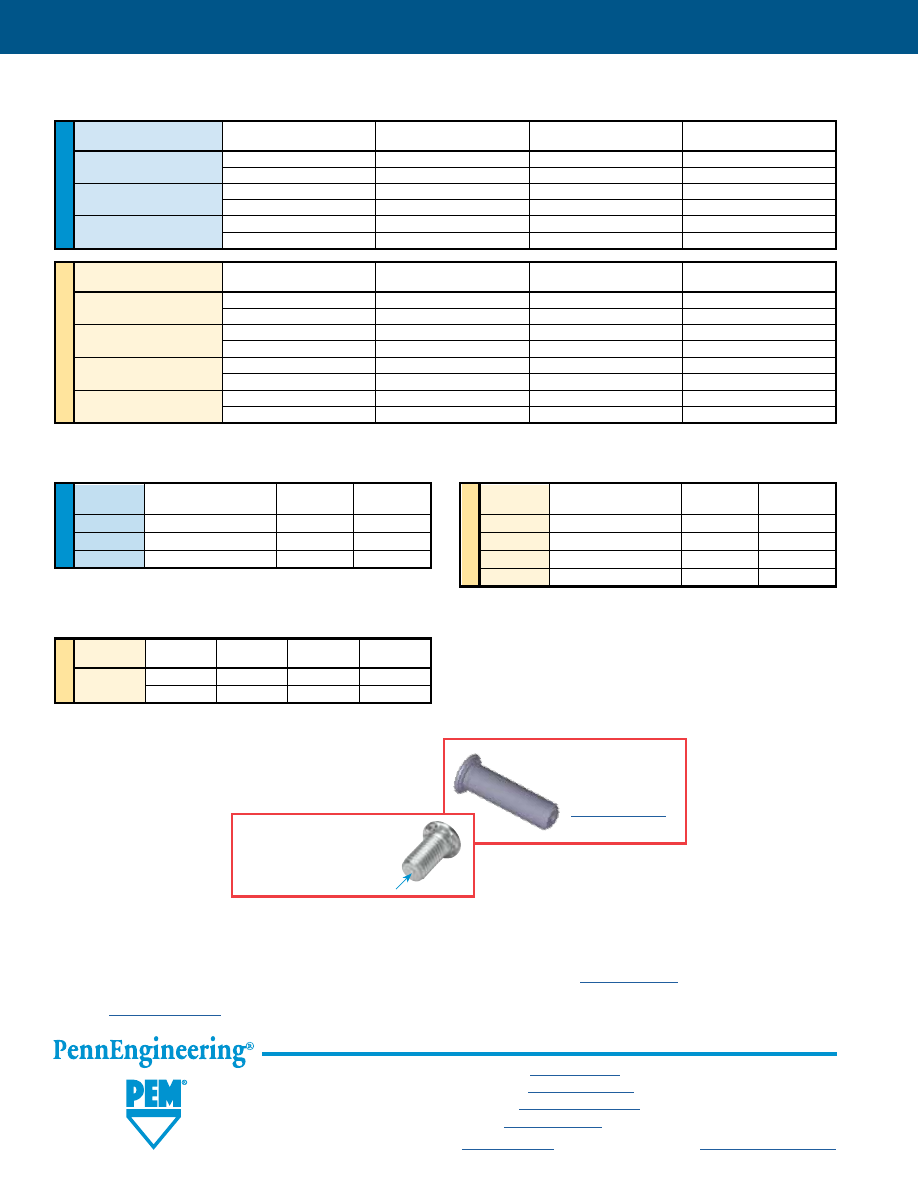
FH-32
ME
T
RIC
PERFORMANCE DATA - TPXS™ PILOT PINS
Pin
Test Sheet
Sheet
Installation
Pushout
Dia. Code
Material
Hardness HRB
(kN)
(kN)
3MM
Aluminum 22
12 0.56
Steel
65
22 0.98
ME
T
RIC
Pin
Test Sheet
Installation
Pushout
Dia. Code
Material
(kN)
(N)
3MM
300 Series Stainless Steel
35
1556
4MM
300 Series Stainless Steel
45
2335
5MM
300 Series Stainless Steel
54
2535
6MM
300 Series Stainless Steel
60
2891
U
NIF
IE
D
Pin
Test Sheet
Installation
Pushout
Dia. Code
Material
(lbs.)
(lbs.)
125
300 Series Stainless Steel
8000
350
187
300 Series Stainless Steel
12000
570
250
300 Series Stainless Steel
14000
650
PERFORMANCE DATA - TP4™ PILOT PINS
U
NIF
IE
D
ME
T
RIC
PERFORMANCE DATA - TPS™ PILOT PINS
Pin
Test Sheet
Sheet
Installation
Pushout
Dia. Code
Material
Hardness HRB
(lbs.)
(lbs.)
125
Aluminum 20
4500 150
Steel
62
6500
250
187
Aluminum 18
6500 230
Steel
60
8000
400
250
Aluminum 18
7000 270
Steel
62
9000
500
Pin
Test Sheet
Sheet
Installation
Pushout
Dia. Code
Material
Hardness HRB
(kN)
(kN)
3MM
Aluminum 22
12 0.56
Steel 65 22 0.98
4MM
Aluminum 19
22 0.89
Steel 66 26.4 1.54
5MM
Aluminum 18 28.6 1.01
Steel 60 35.2 1.76
6MM
Aluminum 18 30.8 1.1
Steel 62 39.6 2.1
All PEM® products meet our stringent quality standards. If you require additional industry or other specific
quality certifications
, special procedures and/or part
numbers are required. Please contact your local sales office or representative for further information.
Regulatory
compliance information
is available in Technical Support section of our website. Specifications subject to change without notice. See our website for the
most current version of this bulletin.
North America:
Danboro, Pennsylvania USA
•
E-mail:
info@pemnet.com
•
Tel: +1-215-766-8853
•
800-237-4736 (USA)
Europe:
Galway, Ireland
•
E-mail:
europe@pemnet.com
•
Tel: +353-91-751714
Asia/Pacific:
Singapore
•
E-mail:
singapore@pemnet.com
•
Tel: +65-6-745-0660
Shanghai, China
•
E-mail:
china@pemnet.com
•
Tel: +86-21-5868-3688
Visit our PEMNET™ Resource Center at
www.pemnet.com
•
Technical support e-mail:
techsupport@pemnet.com
Fastener drawings
and models
are available at
www.pemnet.com
PEM® Dimple
(Registered Trademark)
SELF-CLINCHING STUDS AND PINS
pem-html.html
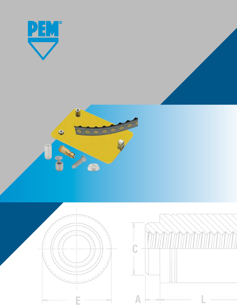
K
™
FASTENERS FOR
USE WITH PC BOARDS
PEM® brand fasteners that utilize,
surface-mount, broaching and flaring
technology for use with PC boards
Bulletin K-1015
Rev 717
pem-html.html
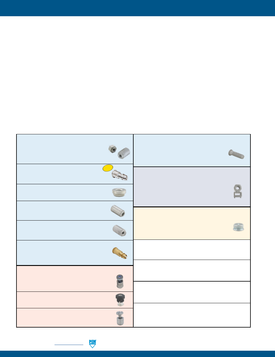
K-2
PennEngineering •
www.pemnet.com
FASTENERS FOR USE WITH PC BOARDS
No matter how sophisticated or advanced, electronic components must be attached reliably and securely if they are
to deliver optimum performance. We offer several fastener products for use with PC boards to satisfy component-to-
board, board-to-board, and board-to-chassis attachment needs.
ReelFast® surface mount fasteners
mount on PC boards in the same manner and at the same time as other surface
mount components prior to the automated reflow solder process. The fasteners simply become another board
component. This alleviates concerns about potential damage to PC boards due to improper secondary installation
operations. The fasteners are provided on tape and reel compatible with existing SMT automated installation
equipment. The benefits of using ReelFast® SMT fasteners are: faster assembly; reduced scrap; reduced handling; and
reduced risk of board damage.
Broaching fasteners
can also offer practical alternatives to “loose” hardware. A broaching fastener is a knurled-shank
fastening device that can be pressed into a hole to provide a permanent, strong, threaded or unthreaded attachment
point in PC boards. They can also be used in aluminum, acrylic, casting and polycarbonate components. Specially
formed axial grooves around the shank of the fastener “broach” or cut into the material, creating a firm, interference-
type fit resistant to rotation. In PC boards, broaching fasteners are recommended for use in non-plated holes.
Broach/flare-mount standoffs
(KFB3™) offer a combined broach/flare feature for even greater pullout performance
in PC board materials.
NUTS AND SPACERS/STANDOFFS
SMTSO™/SMTSOB™ -
ReelFast® surface mount
nuts and standoffs are available threaded and
unthreaded -
PAGE 4
SMTSS™ -
ReelFast® SNAP-TOP® standoffs
feature a spring action to hold PC Board securely
without screws or threaded hardware -
PAGE 5
KF2™/KFS2™ -
Broaching nuts, internally
threaded for mounting on PC boards -
PAGE 6
KFE™/KFSE™ -
Broaching standoffs, threaded or
unthreaded for stacking or spacing -
PAGE 7
KFB3™ -
Broach/flare-mount standoffs with
greater pullout performance -
PAGE 7
KSSB™ -
Broaching, SNAP-TOP® standoffs
feature a spring action to hold PC board securely
without screws or threaded hardware -
PAGE 8
CAPTIVE PANEL SCREWS
SMTPFLSM™ -
ReelFast® surface mount spring-
loaded captive panel screws -
PAGE 9
SMTPF™ -
ReelFast® surface mount captive
panel screws -
PAGE 10
PFK™ -
Broaching panel fastener assemblies for
mounting on PC boards -
PAGE 11
STUDS
KFH™ -
Threaded broaching studs for use
as solderable connectors or as permanently
mounted studs on PC boards -
PAGE 11
RIGHT ANGLE FASTENERS
SMTRA™ -
ReelFast® R’ANGLE® surface mount
fasteners provide strong re-usable threads at
right angles to PC boards -
PAGE 12
SHEET JOINING FASTENERS
SFK™ -
SpotFast® clinch/broach mount fasteners
for joining metal to PCB/plastic panels -
PAGE 13
MATERIAL AND FINISH SPECIFICATIONS -
PAGE 14
INSTALLATION -
PAGES 15-17
PERFORMANCE DATA -
PAGES 18-19
OTHER FASTENERS FOR USE WITH PC BOARDS -
PAGE 20
New
© 2017 PennEngineering.
pem-html.html
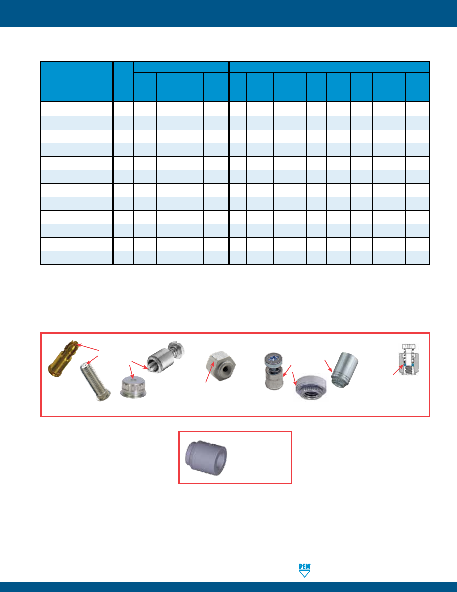
PennEngineering •
www.pemnet.com
K-3
FASTENERS FOR USE WITH PC BOARDS
SMTSO/SMTSOB
4
• • •
SMTSS
5
• • •
KF2/KFS2
6
• •
KFE/KFSE
7
• •
KFB3
7
• •
KSSB
8
• • •
SMTPFLSM
9
•
•
SMTPF
10
•
• •
PFK
11
• •
KFH
11
• •
SMTRA
12
• •
SFK
13
• •
•
M o u n t i n g T y p e s
QUICK REFERENCE CHART
P r i m a r y U s e
To be sure that you are getting genuine PEM® brand fasteners, look for the unique PEM® product markings and identifiers.
PEM® TRADEMARKS
PEM® Blue
Nylon Ring
(Trademark)
PEM® Double Notch
(Registered Trademark)
PEM® Dimple
(Registered
Trademark)
PEM® “Two Groove”
(Registered
Trademark)
PEM® Page
Fastener
No.
Fastener drawings
and models are
available at
www.pemnet.com
Right
Sheet
tp
Broach/ Surface Clinch/
Spacer/
Snap
Captive Color
Angle
Sheet
Broach Flare
Mount Broach
Nut Standoff Attachment Stud
Screw Coding Attachment Joining
pem-html.html
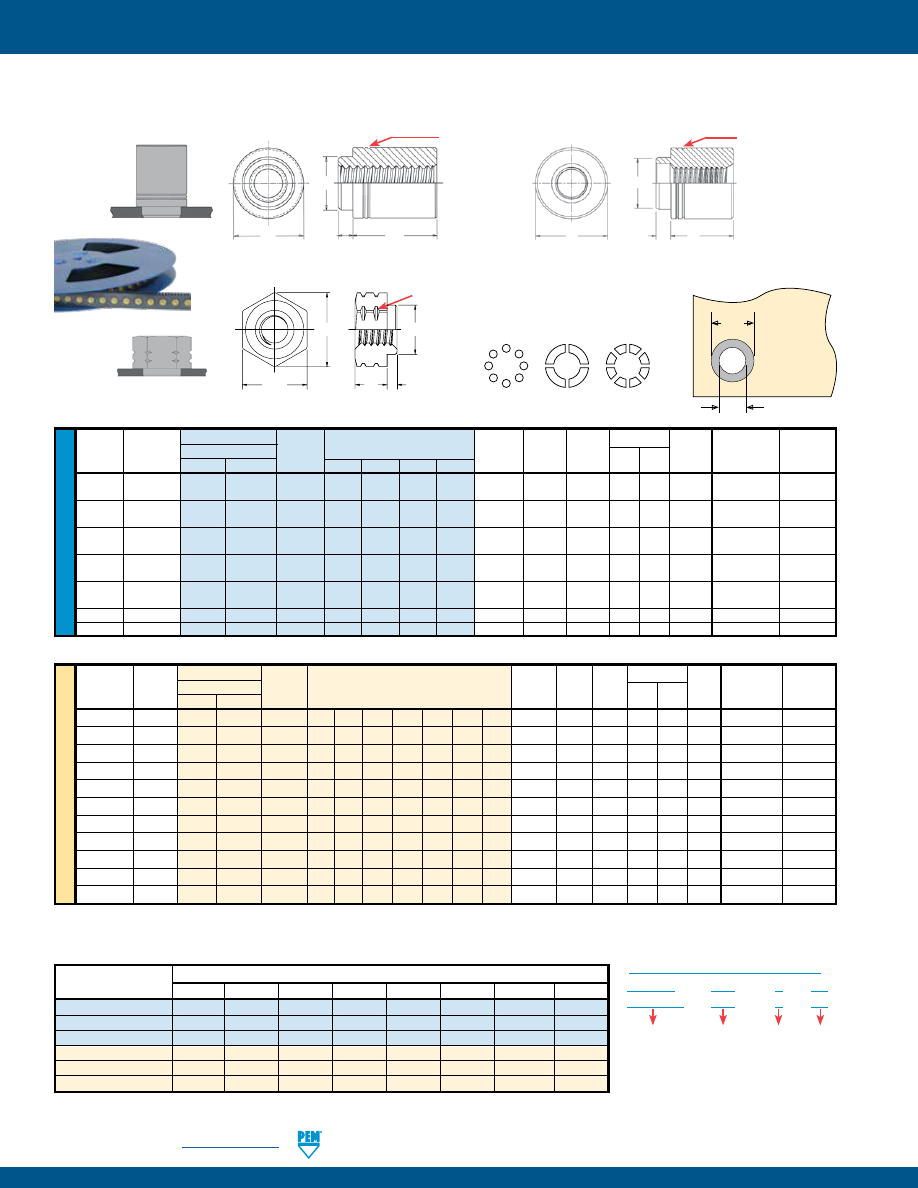
K-4
PennEngineering •
www.pemnet.com
FASTENERS FOR USE WITH PC BOARDS
ME
TR
IC
U
NIF
IE
D
SMTSO™/SMTSOB™ ReelFast® SURFACE MOUNT NUTS AND SPACERS/STANDOFFS
Packaged on 330 mm recyclable reels. Tape width is 24 mm. Supplied with polyimide patch for vacuum pick up. Reels conform to EIA-481.
Thru Type
Thread or
Min.
E
Ø
H Hole Size
Ø
D
Thread
Hole Fastener Material
Thru Hole
Sheet
A
C
H
In Sheet
Min. Solder
Size
+.004 –.003
Steel Brass Code .062 .125 .250 .375
Thickness
Max.
Max.
Ref. ±.005
Nom.
+.003 –.000
Pad
.060-80
—
SMTSO —
080
2 4 — — .020 .019 .095 .144 .125
.098
.165
(#0-80)
.086-56
—
SMTSO SMTSOB 256 2 4 8
(1)
12
(1)
.060 .060 .142 — .219 —
.147
.244
(#2-56)
.112-40
—
SMTSO SMTSOB 440 2 4 8
(1)
12
(1)
.060 .060 .161 — .219 —
.166
.244
(#4-40)
.138-32
—
SMTSO SMTSOB 632 2 4 8
(1)
12
(1)
.060 .060 .208 — .281 —
.213
.306
(#6-32)
.164-32
—
SMTSO SMTSOB 832 2 4 8
(1)
12
(1)
.060 .060 .245 — .344 —
.250
.369
(#8-32)
—
.116
SMTSO SMTSOB 116
2
4
8 12 .060 .060 .161 — .219 —
.166
.244
—
.143
SMTSO SMTSOB 143
2
4
8 12 .060 .060 .208 — .281 —
.213
.306
Length Code “L” ±.005
(Length code in 32nds of an inch)
Thread
Thru Hole Type
Thread or
Min.
E
Ø
H Hole Size
Ø
D
Size x
+0.10 Fastener Material
Thru Hole
Sheet
A
C
H
In Sheet
Min. Solder
Pitch –0.08 Steel Brass Code
Thickness
Max.
Max.
Ref.
±0.13
Nom. +0.08 Pad
S1
— SMTSO —
M1 1 2 3 — — — — 0.5 0.48 2.41 3.66 — 3.18
2.5
4.19
S1.2
— SMTSO — M1.2 1 2 3 — — — — 0.5 0.48 2.41 3.66 — 3.18
2.5
4.19
S1.4
— SMTSO — M1.4 1 2 3 — — — — 0.5 0.48 2.41 3.66 — 3.18
2.5
4.19
M1.6 x 0.35
—
SMTSO
—
M1.6
1
2
3
—
—
—
—
0.5
0.48
2.41
3.66
—
3.18
2.5
4.19
M2 x 0.4
—
SMTSO SMTSOB
M2
—
2
3
4
(1)
6
(1)
8
(1)
10
(1)
1.53 1.53 3.6 — 5.56 —
3.73
6.2
M2.5 x 0.45
—
SMTSO SMTSOB
M25
—
2
3
4
(1)
6
(1)
8
(1)
10
(1)
1.53 1.53 4.09 — 5.56 —
4.22
6.2
M3 x 0.5
—
SMTSO SMTSOB
M3
—
2
3
4
(1)
6
(1)
8
(1)
10
(1)
1.53 1.53 4.09 — 5.56 —
4.22
6.2
M3.5 x 0.6
—
SMTSO SMTSOB
M35
—
2
3
4
(1)
6
(1)
8
(1)
10
(1)
1.53 1.53 5.28 — 7.14 —
5.41
7.77
M4 x 0.7
—
SMTSO SMTSOB
M4
—
2
3
4
6
(1)
8
(1)
10
(1)
1.53 1.53 6.22 — 8.74 —
6.35
9.37
—
3.6 SMTSO SMTSOB 3.6 — 2 3 4 6 8 10 1.53 1.53 5.28 — 7.14 —
5.41
7.77
—
4.2 SMTSO SMTSOB 4.2 — 2 3 4 6 8 10 1.53 1.53 6.22 — 8.74 —
6.35
9.37
Length Code “L” ±0.13
(Length code in millimeters)
Thread/Thru-Hole
Length Code
Size
1 2 3 4 6 8 10 12
080
—
3500 / 8
—
2000 / 8
—
—
—
—
256, 440, 632, 116, 143
—
1500 / 12
—
1000 / 12
—
650 / 12
—
300 / 16
832
—
1100 / 16
—
800 / 16
—
500 / 16
—
300 / 16
M1, M1.2, M1.4, M1.6
3500 / 8
2500 / 8
2000 / 8
—
—
—
—
—
M2, M25, M3, M35, 3.6
—
1500 / 12
1000 / 12
900 / 12
650 / 12
375 / 16
300 / 16
—
M4, 4.2
—
1100 / 16
800 / 16
675 / 16
500 / 16
375 / 16
300 / 16
—
Ø
H
Ø
D
Solder
Pad
Plated through hole
not required.
NUMBER OF PARTS PER REEL / PITCH (MM) FOR EACH SIZE
SMTSO –
440 – 8
ET
SMTSOB – 440 – 8
ET
Type and
Material
PART NUMBER DESIGNATION
Finish
Thread or
Thru Hole
Code
Length
Code
All dimensions are in inches.
All dimensions are in millimeters.
Stencil Masking Examples
E
H
C
A
L
PEM® Double Notch (Registered Trademark)
Metric -1 length not marked
Thread sizes 080, S1, S1.2, S1.4 and M1.6
Thread/thru hole sizes 2-56, 4-40, 6-32, 8-32, 116, 143, M2, M2.5, M3, M3.5, M4, 3.6, and 4.2
SMTSO
(1) SMTSOB fasteners with this length code have a shank counterbore.
SMTSOB
E
A
C
L
PEM® “Two Groove”
(Registered Trademark)
E
A
C
L
PEM® “Two Groove”
(Registered Trademark)
microPEM® SMTSO NUTS
pem-html.html
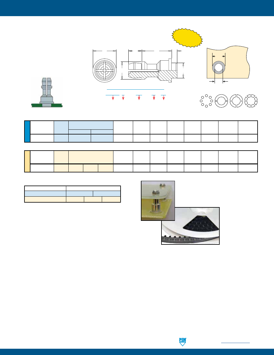
PennEngineering •
www.pemnet.com
K-5
FASTENERS FOR USE WITH PC BOARDS
SMTSS™ REELFAST® SNAP-TOP® STANDOFFS
Ø
H
Ø
D
Solder
Pad
Plated through hole
not required.
NUMBER OF PARTS PER REEL
Packaged on 330 mm recyclable reels. Tape width is 24 mm.
Supplied with polyimide patch for vacuum pick up. Reels conform to EIA-481.
E
P
L
A
C
B
U
NIF
IE
D
Top
Board
Min.
ØH
Hole
ØD
Mounting Hole
Type and
Sheet
A
C
E
B
P
Size in Sheet
Min.
Diameter Code
Material
.250 .375
Thickness
Max.
Max.
±.005
±.005
±.005
+.003 –.000
Solder Pad
156 SMTSSS 8
12
.060 .060 .161 .250 .188 .141
.166
.276
Length Code “L” ±.005
(Length Code in 32nds of an inch)
All dimensions are in inches.
ME
TR
IC
Top
Board
Min.
ØH
Hole
ØD
Mounting Hole
Type and
Sheet
A
C
E
B
P
Size in Sheet
Min.
Diameter Code
Material
Thickness Max. Max. ±0.13 ±0.13 ±0.13 +0.08 Solder
Pad
4MM SMTSSS 6
8 10
1.53
1.53 4.09 6.35 4.8 3.58
4.22
7
Length Code “L” ±0.13
(Length Code in millimeters)
All dimensions are in millimeters.
Type, Material and Size Length Code / Number of Parts per Reel
SMTSSS-156
-8 / 280
-12 / 220
SMTSSS-4MM
-6 / 300
-8 / 250
-10 / 200
SMTSS S – 156 – 12 ET
PART NUMBER DESIGNATION
Panel 2 (Top)
Mounting Hole
Diameter Code
Length
Code
Finish
Type Material
Stencil Masking Examples
NEW!
NOTE: REELFAST® SNAP-TOP®
SMTSS™ standoffs are for on-only
applications. For removal applications,
mounting hole can be increased to
reduce removal force.
pem-html.html
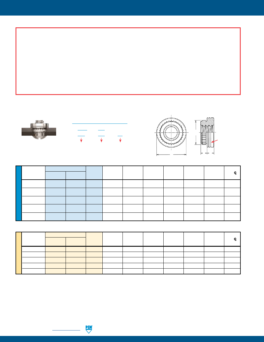
K-6
PennEngineering •
www.pemnet.com
FASTENERS FOR USE WITH PC BOARDS
ME
TR
IC
U
NIF
IE
D
Type
A
Min.
Hole Size
Min. Dist.
Thread
Thread (Shank)
Sheet
In Sheet C E
T Hole
C/L
Size
Carbon Stainless Code Max.
Thickness
+.003 –.000 ±.003 ±.005 ±.005 To Edge
Steel Steel
.086-56
KF2 KFS2 256 .060 .060 .147 .165 .219 .065 0.16
(#2-56)
.112-40
KF2 KFS2 440 .060 .060 .166 .184 .219 .065 0.17
(#4-40)
.138-32
KF2 KFS2 632 .060 .060 .213 .231 .281 .065 0.22
(#6-32)
.164-32
KF2 KFS2 832 .060 .060 .250 .268 .344 .096 0.25
(#8-32)
.190-32
KF2 KFS2 032 .060 .060 .272 .290 .375 .127 0.28
(#10-32)
All dimensions are in inches.
All dimensions are in millimeters.
Thread Type
A
Min.
Hole Size
Min. Dist.
Size x
Thread
(Shank)
Sheet
In Sheet C E
T Hole
C/L
Pitch
Carbon Stainless Code Max.
Thickness
+0.08 ±0.08 ±0.13 ±0.13
To Edge
Steel Steel
M2
x 0.4
KF2
KFS2
M2
1.53
1.53
3.73
4.19
5.56
1.5
4.2
M2.5
x 0.45
KF2
KFS2
M2.5
1.53
1.53
4.22
4.68
5.56
1.5
4.4
M3
x 0.5
KF2
KFS2
M3
1.53
1.53
4.22
4.68
5.56
1.5
4.4
M4
x 0.7
KF2
KFS2
M4
1.53
1.53
6.4
6.81
8.74
2
6.4
M5
x 0.8
KF2
KFS2
M5
1.53
1.53
6.9
7.37
9.53
3
7.1
KF2™/KFS2™ BROACHING NUTS
KF2 – 832 – ET
Type and
Material
PART NUMBER DESIGNATION
Finish
Thread
Code
KFS2 – 832
E
C
A
T
PEM® “Two Groove”
(Registered Trademark)
NOTE ABOUT PLATED AND UNPLATED MOUNTING HOLES FOR BROACHING FASTENERS
Broaching and broach/flare types are designed for unplated mounting hole applications. If used in plated mounting holes, the stresses involved
can damage the plating, push out the plating entirely, or break any traces inside the board that might be connected to the plated hole. When
installing into non-plated mounting holes there may even be issues with delamination, measeling or crazing in some instances.
Increasing the mounting hole size +.005” to +.008” /+0.13 mm to +0.2 mm may relieve these conditions. If increasing the mounting hole does
not correct the issue then we recommend our surface-mount type fasteners.
It is always recommended that you try the fasteners in your specific application before full production begins. We are happy to provide samples
for this purpose.
General recommendations for “Keep Out” areas are the same as our “Min. Distance Hole C/L to Edge” dimensions stated in the dimensional
charts of our bulletin.
pem-html.html
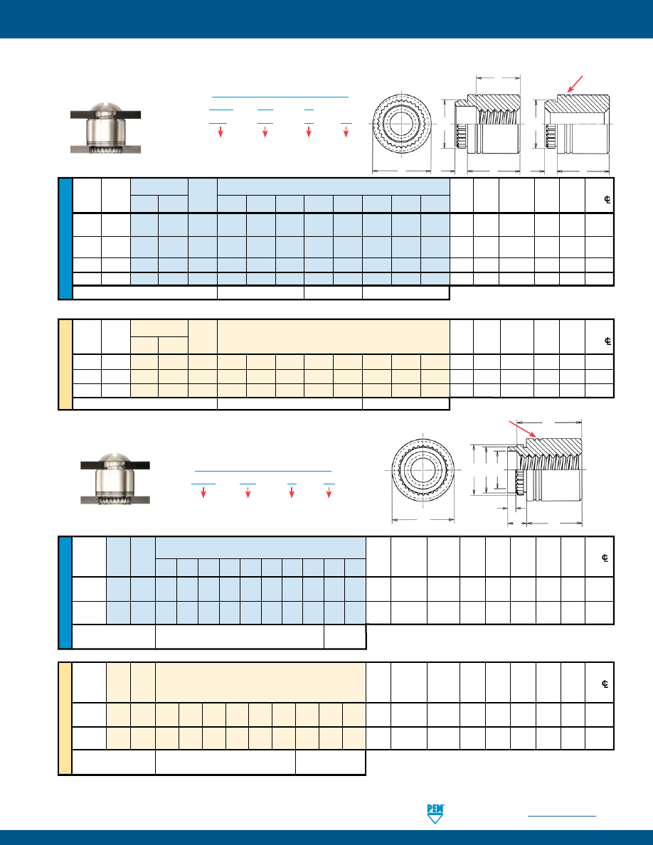
PennEngineering •
www.pemnet.com
K-7
FASTENERS FOR USE WITH PC BOARDS
ME
TR
IC
U
NIF
IE
D
ME
TR
IC
U
NIF
IE
D
Hole Size
Min.
Thread Thread
A in Sheet
Dist.
Size Type
Code
(Shank)
Sheet +.005 B C E K P Hole
C/L
(1) (1) Max. Thickness –.001 ±.003 Max. ±.005 ±.003 ±.010 To
.062
.125
.187
.250
.312
.375
.500
.625
.750
1.00
Edge
.112-40
KFB3 440 2 4 6 8 10 12 16 20 — — .09 .050-.065 .166 .122 .165 .219 .179 .040 .17
(#4-40)
.138-32
KFB3 632 2 4 6 8 10 12 16 20 24 32 .09 .050-.065 .213 .171 .212 .280 .226 .040 .22
(#6-32)
“F” Min. Thread Length
Full
.375 Blind
(Where Applicable)
Hole Size
Min.
Thread
Thread
A in Sheet Dist.
Size
x
Type
Code
(Shank)
Sheet +0.13 B C E K P Hole
C/L
Pitch
Max. Thickness –0.03 ±0.08 Max. ±0.13 ±0.08 ±0.25 To
Edge
M3 x 0.5 KFB3 M3 2 3 4 6 8 10 12 14 16 2.29 1.27-1.65 4.22 3.23 4.2 5.56 4.55 1 4.33
M4 x 0.7 KFB3 M4 2 3 4 6 8 10 12 14 16 2.29 1.27-1.65 6.4 5.23 6.33 8.74 6.68 1 6.36
“F” Min. Thread Length
Full
9.5 ±0.4
(Where Applicable)
Length “L” ±.005
(Length Code is in 32nds of an inch)
Length “L” ±0.13
(Length Code is in millimeters)
Thru
Type
Thread
A
Min.
Hole Size
Min.
Thread
Hole
or Thru
(Shank) Sheet
In Sheet
C
E
Dist.
Size +.004 Carbon Stainless Hole
(1) (1) (1)
Max.
Thick- +.003 –.000 ±.003
±.005 Hole
C/L
–.003 Steel Steel
Code
.125
.250
.375
.500
.625
.750
.875
1.00
ness
To Edge
.112-40
— KFE KFSE 440 4
8
12 16 20 24 — — .060 .060 .166 .184 .219 .17
(#4-40)
.138-32
— KFE KFSE 632 4
8
12 16 20 24 28 32 .060 .060 .213 .231 .281 .22
(#6-32)
—
.116
KFE KFSE 116
4
8
12
16
20
24
—
— .060 .060 .166
.184 .219 .17
—
.143 KFE KFSE 143
4
8
12
16
20
24
28
32 .060 .060 .213
.231 .281 .22
“F” Minimum Thread Length (Where Applicable)
Full
.375 ± .016
.375 Blind
Thru
Type
Thread
Length “L” ±0.13
A
Min.
Hole Size
Min.
Thread
Hole
or Thru
(Length Code is in millimeters)
(Shank) Sheet
In Sheet
C
E
Dist.
Size x
+0.10
Carbon Stainless Hole
Max. Thick- +0.08 ±0.08 ±0.13 Hole
C/L
Pitch –0.08 Steel Steel
Code
ness
To
Edge
M3 x 0.5
—
KFE
KFSE
M3
3
4
6
8
10
12
14
16
1.53
1.53
4.22
4.68
5.56
4.4
— 3.6 KFE KFSE 3.6
3
4
6
8
10
12
14
16 1.53 1.53 5.41 5.87 7.14 5.5
— 4.2 KFE KFSE 4.2
3
4
6
8
10
12
14
16 1.53 1.53
6.4 6.86 8.74 7.1
“F” Minimum Thread Length (Where Applicable)
Full
9.5 ± 0.4
Length “L” ±.005
(Length Code is in 32nds of an inch)
(1) Blind at shank end with .375” minimum thread length from head end.
KFE™/KFSE™ BROACHING STANDOFFS
KFB3™ BROACH/FLARE-MOUNT STANDOFFS
All dimensions are in inches.
All dimensions are in millimeters.
KFB3 – 632 – 12 ET
Type and
Material
PART NUMBER DESIGNATION
Finish
Thread
Code
Length
Code
All dimensions are in inches.
All dimensions are in millimeters.
KFE – 632 – 12 ET
Type and
Material
PART NUMBER DESIGNATION
Finish
Thread
or Thru Hole
Code
Length
Code
KFSE – 632 – 12
E
A
L
F
A
L
C
C
PEM® “Two Groove” (Registered Trademark)
F
K C B
E
A
L
P
PEM® “Two Groove”
(Registered Trademark)
pem-html.html
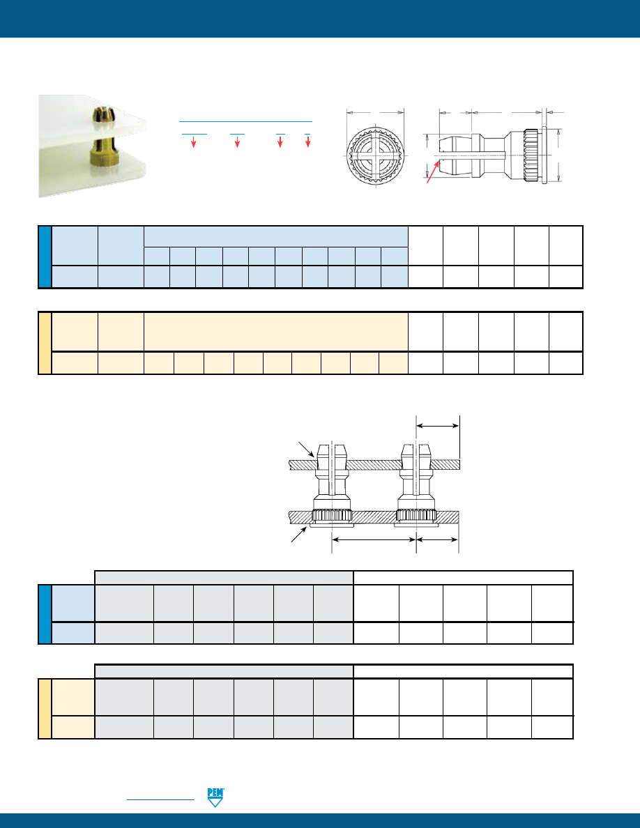
K-8
PennEngineering •
www.pemnet.com
FASTENERS FOR USE WITH PC BOARDS
ME
TR
IC
U
NIF
IE
D
Top Board
Mounting
Type Hole B C H P T
Diameter .250 .312 .375 .437 .500 .562 .625 .750 .875 1.00 ±.005 ±.003 ±.005 ±.005 ±.005
Code
KSSB
156
8 10 12 14 16 18 20 24 28 32 .188 .226
.250
.141 .020
Top Board
Mounting
Type Hole B C H P T
Diameter ±0.13 ±0.08 ±0.13 ±0.13 ±0.13
Code
KSSB
4MM 8 10 12 14 16 18 20 22 25 4.8 5.74 6.35 3.58 0.51
Length “L” ±0.13
(Length Code is in millimeters)
Mounting Hole A
Mounting Hole B
Edge
C
2
Edge
C
1
Location
Tolerance
PANEL 2 (TOP)
PANEL 1 (BOTTOM)
Length “L” ±.005
(Length Code is in 32nds of an inch)
KSSB™ BROACHING SNAP-TOP® STANDOFFS
KSSB™ APPLICATION DATA
All dimensions are in inches.
All dimensions are in millimeters.
(1)
HRB - Hardness Rockwell “B” Scale. HB - Hardness Brinell.
(2)
Available for thicker boards on special order.
ME
TR
IC
U
NIF
IE
D
Bottom Edge
Top Edge
Hardness Mounting Panel Thickness Distance
Location
Hardness Mounting Panel Thickness
Distance
Type
Max.
Hole B
Material
Min.
C
1
Min.
Tolerance
Max.
Hole A
Material
Range
C
2
Min.
(1)
+.003 -.000
+.003 -.000
(2)
KSSB
HRB 65 / HB 116
.213
PC Board .050 .220 ±.005 No Limit
.156
PC Board
.040 - .070
.100
or Metal
Panel 1
Panel 2
Bottom Edge
Top Edge
Hardness Mounting Panel Thickness Distance
Location
Hardness Mounting Panel Thickness
Distance
Type
Max.
Hole B
Material
Min.
C
1
Min.
Tolerance
Max.
Hole A
Material
Range
C
2
Min.
(1) +0.08 +0.08 (2)
KSSB
HRB 65 / HB 116
5.41
PC Board 1.27 5.59 ±0.13 No Limit 4 PC Board
1 - 1.8
2.54
or Metal
Panel 1
Panel 2
All dimensions are in inches.
All dimensions are in millimeters.
KSSB – 156 – 12
X
Type and
Material
PART NUMBER DESIGNATION
Top Board
Mounting
Hole
Diameter
Code
Length
Code
Finish
T
P
H
B
L
C
PEM® Dimple
(Registered Trademark)
pem-html.html
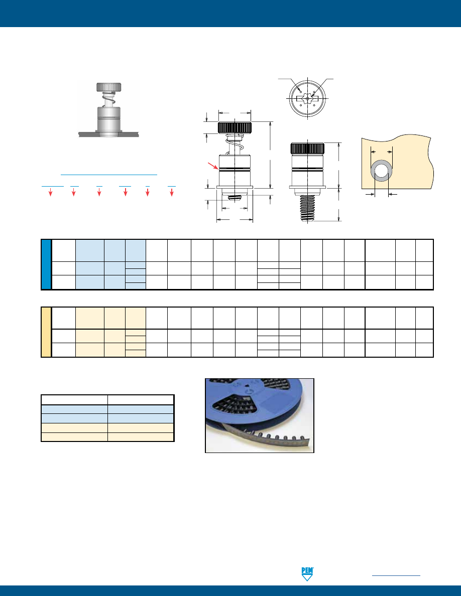
PennEngineering •
www.pemnet.com
K-9
FASTENERS FOR USE WITH PC BOARDS
All dimensions are in inches.
U
NIF
IE
D
Screw A Min.
ØK Hole Size ØD Min.
Thread
Thread Length (Shank) Sheet
C
E
1
E
2
G
1
G
2
H T
1
T
2
in Sheet
Solder Driver
Size
Type
Code Code Max. Thickness
Max.
±.010
Nom
±.025
±.025
±.010
Nom.
Nom.
+.003 -.000
Pad
Size
.112-40
SMTPFLSM 440 0 .063 .063 .215 .280 .300 .040 .210 .100 .38 .55
.220 .340 T15
(#4-40)
1 .100
.270
.138-32
SMTPFLSM 632 0 .063 .063 .247 .310 .320 .040 .240 .100 .42 .62
.252 .400 T15
(#6-32)
1 .100
.300
All dimensions are in millimeters.
ME
TR
IC
Screw A Min.
ØK Hole Size ØD Min.
Thread
Thread Length (Shank) Sheet
C
E
1
E
2
G
1
G
2
H T
1
T
2
in Sheet
Solder Driver
Size
Type
Code Code Max. Thickness Max. ±0.25 Nom ±0.64 ±0.64 ±0.25 Nom. Nom. +0.08 Pad Size
M3 x 0.5
SMTPFLSM
M3
0 1.6 1.6 5.46 7 7.6 1 5.3 2.5 9.6 14 5.6 8.6 T15
1 2.5
6.8
M3.5 x 0.6
SMTPFLSM
M3.5
0 1.6 1.6 6.27 7.9 8.13 1 6.1 2.5 10.7 15.7 6.4 10.2 T15
1 2.5
7.62
SMTPFLSM™ ReelFast® SURFACE MOUNT CAPTIVE PANEL SCREWS
Ø
H
Ø
D
Solder
Pad
Plated through hole
not required.
SMTPF LS
M – 440 – 0
ET
Type
PART NUMBER DESIGNATION
Thread
Code
Driver
Anti-cross
Thread
Feature
Length
Code
Finish
NUMBER OF PARTS PER REEL
Packaged on 330 mm recyclable reels. Tape width is 24 mm. Supplied with polyimide patch for vacuum pick up. Reels conform to EIA-481.
Thread Size
Parts Per Reel
440
200
632
150
M3
200
M3.5
150
E
1
H
C
A
E
2
T
2
T
1
G
1
G
2
Dimples on head designate
metric thread.
Torx®/slot driver size.
(See chart)
PEM® “Two Groove”
(Registered Trademark)
pem-html.html
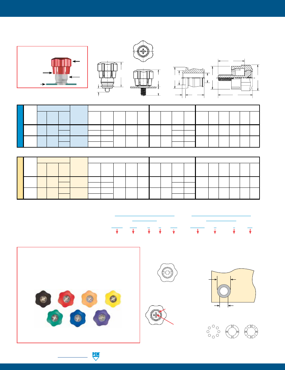
K-10
PennEngineering •
www.pemnet.com
FASTENERS FOR USE WITH PC BOARDS
U
NIF
IE
D
Available with Torx®
recess on special order.
Stencil Masking Examples
SMTPR – 6 – 1
ET
Type
PART NUMBER DESIGNATION
FOR RETAINER
Finish
Retainer
Size
Shank
Code
PSHP – 632 – 0
L
001
Type
PART NUMBER DESIGNATION
FOR SCREW
Cap
Style
(Lobed)
Thread
Code
Length
Code
Color
Code
(Standard
Black)
Screw Part Number
Assembly Dimensions
Screw Dimensions
Retainer Dimensions
Screw
Retainer
Total A
Min.
Thread
Thread Length
Part
G
P
T
1
T
2
Radial C
1
E
1
L
T (Shank) Sheet B
C
E R
Size
Type
Code
Code
Number
± .025
± .025
Nom.
Nom.
Float
±.010
±.010
±.015
Nom.
Max.
Thick. ±.003
Max. Nom. ±.005
.112-40
PSHP 440
0
SMTPR-6-1
.188 .000
.478 .646 .015 .440 .542
.510 .663
.060 .060 .167 .249 .375 .325
(#4-40)
1 .248
.026
.570
.723
.138-32
PSHP 632
0
SMTPR-6-1
.188 .000
.478 .646 .020 .440 .542
.510 .663
.060 .060 .167 .249 .375 .325
(#6-32)
1 .248
.026
.570
.723
The colors shown here (codes #002 thru #007) are non-stocked
standards and available on special order. Since actual cap colors may
vary slightly from those shown here, we recommend that you request
samples for color verification. If you require a custom color or you need
a “color matched” cap, please contact us.
Std. Black #001 Red #002 Orange #003 Yellow #004
Green #005
Blue #006
Violet #007
Non-flammable UL 94-V0 plastic caps are available on special order.
All dimensions are in inches.
All dimensions are in millimeters.
COLOR CAPABILITIES FOR TYPE PSHP SCREW
SMTPF™ ReelFast® SURFACE MOUNT CAPTIVE PANEL SCREWS
ME
TR
IC
Screw Part Number
Assembly Dimensions
Screw Dimensions
Retainer Dimensions
Thread
Screw
Retainer
Total A
Min.
Size x
Thread Length
Part
G
P
T
1
T
2
Radial C
1
E
1
L
T (Shank) Sheet B
C
E R
Pitch
Type
Code
Code
Number
± 0.64
± 0.64
Nom.
Nom.
Float
±0.25 ±0.25
±0.38
Nom.
Max.
Thick. ±0.08
Max. Nom. ±0.13
M3 x 0.5 PSHP
M3
0
SMTPR-6-1
4.78 0
12.14 16.41 .38 11.18 13.77
12.95 16.84
1.53 1.53 4.24 6.33 9.53 8.26
1 6.3
.66
14.48
18.36
M3.5 x 0.6 PSHP M3.5
0
SMTPR-6-1
4.78 0
12.14 16.41 .51 11.18 13.77
12.95 16.84
1.53 1.53 4.24 6.33 9.53 8.26
1 6.3
.66
14.48
18.36
RETAINER -
Packaged on 330 mm recyclable reels of 465
pieces. Tape width is 24 mm. Supplied with Kapton® patch for
vacuum pick up. Reels conform to EIA-481.
SCREW -
Packaged in bags. Retainers and screws are sold
separately.
.396”/
10.06 mm
Min.
Solder
Pad
Plated through hole
not required.
.250”
+.003 –.000
6.35 mm
+0.08
Four dimples on
head designate
metric thread.
Metal Phillips Recess
#4-40 & M3 = #1
#6-32 & M3.5 = #2
When Assembled
Spring action of
plastic “fingers”
holds screw
in retracted
position.
PSHP
SMTPR
PC Board
R
E
A
C
B
E
1
L
T
C
1
T
2
T
1
G
P
Patented.
pem-html.html
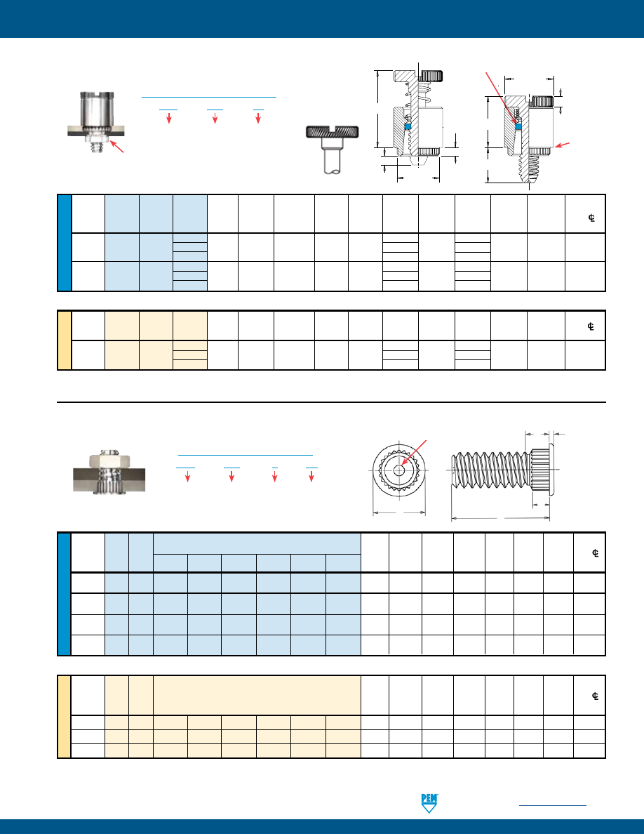
PennEngineering •
www.pemnet.com
K-11
FASTENERS FOR USE WITH PC BOARDS
ME
TR
IC
U
NIF
IE
D
Hole
Max.
Min.
Thread
Thread
A
Min.
Size
in
Hole
Dist.
Size
Type
Code
(Shank)
Sheet
Sheet
Size
in
H
S
T
Hole
C/L
Max.
Thickness
+.003
Attached
±.010
Max.
±.005
To
.250 .312 .375 .500 .625 .750
–.000 Parts
(1)
Edge
.112-40
KFH 440 4
5
6
8
10
12 .065 .060 .120 .145 .180 .09 .020 .15
(#4-40)
.138-32
KFH 632 4
5
6
8
10
12 .065 .060 .140 .170 .200 .09 .020 .19
(#6-32)
.164-32
KFH 832 4
5
6
8
10
12 .065 .060 .166 .195 .225 .09 .020 .20
(#8-32)
.190-32
KFH 032 4
5
6
8
10
12 .065 .060 .189 .220 .250 .09 .020 .20
(#10-32)
Length “L” ±.010
(Length Code is in 16ths of an inch)
Hole
Max.
Min.
Thread
Thread
A
Min.
Size
in
Hole
Dist.
Size
x
Type
Code
(Shank)
Sheet
Sheet
Size
in
H
S
T
Hole
C/L
Pitch
Max.
Thickness
+0.08
Attached
±0.25
Max.
±0.13
To
Parts
(1)
Edge
M3 x 0.5
KFH
M3
6
8
10
12
15
18
1.65
1.53
3
3.7
4.58
2.3
0.51
3.8
M4 x 0.7
KFH
M4
6
8
10
12
15
18
1.65
1.53
4.2
4.8
5.74
2.3
0.51
5.1
M5 x 0.8
KFH
M5
6
8
10
12
15
18
1.65
1.53
5
5.8
6.6
2.3
0.51
5.3
Length “L” ±0.25
(Length Code is in millimeters)
KFH™ BROACHING STUDS
All dimensions are in inches.
All dimensions are in millimeters.
KFH – 632 – 8 ET
Type and
Material
PART NUMBER DESIGNATION
Finish
Thread
Code
Length
Code
(1) Threads are gaugeable to within 2 pitches of the “S” Max. dimension. A class 3B/5H maximum material commercial nut shall pass up to the “S” Max.
dimension.
S
T
H
A
L
PEM® Dimple (Registered Trademark)
ME
TR
IC
U
NIF
IE
D
Hole
Thread
Thread
Screw
A
Min.
Size In
C
E
G
H
P
T
1
T
2
Min. Dist.
Size
Type
Code Length (Shank) Sheet
Sheet ±.003 ±.010 ±.016 ±.005 ±.025 Max.
Nom. Hole
CL
Code
Max.
Thickness
+.003 –.000
To Edge
40 .250 .000
.112-40 PFK 440 62 .060 .060 .265 .283 .312 .375 .072 .125 .36 .54 .20
(#4-40) 84 .500 .250
40 .250 .000
.138-32 PFK 632 62 .060 .060 .281 .299 .344 .375 .072 .125 .36 .54
.26
(#6-32) 84 .500 .250
Thread
Thread
Screw
A
Min.
Hole Size
C
E
G
H
P
T
1
T
2
Min. Dist.
Size x
Type
Code
Length
(Shank)
Sheet
In Sheet
±0.08
±0.25
±0.4
±0.13
±0.64
Max.
Nom. Hole
CL
Pitch
Code
Max.
Thickness
+0.08
To
Edge
40 6.4 0
M3 x 0.5
PFK
M3
62
1.53
1.53
6.73
7.19
7.92
9.5
1.83
3.2
9.14
13.72
5.08
84
12.7
6.4
*Retaining rings are plastic with normal 250°F / 120°C temperature limit.
PFK™ BROACHING CAPTIVE PANEL SCREWS
All dimensions are in inches.
All dimensions are in millimeters.
PFK – 632 – 62
Type
PART NUMBER DESIGNATION
Thread
Code
Screw
Length
Code
Shown here with
self-clinching mating nut
Diagonal knurl
identifies metric
thread sizes
T
2
T
1
P
C
A
G
H
E
Shoulder
provides
positive
stop during
installation.
PEM® Blue Nylon Ring*
(Trademark)
pem-html.html
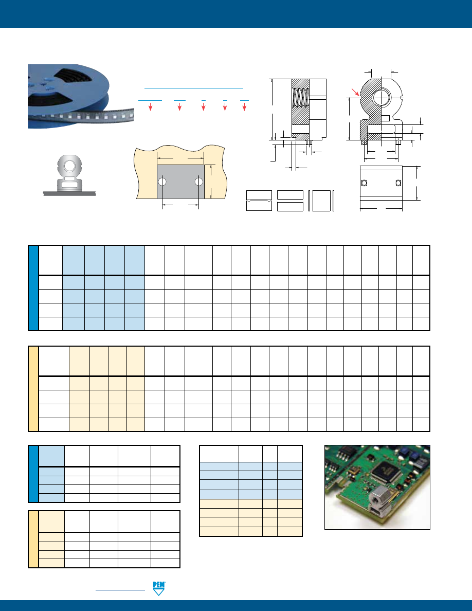
K-12
PennEngineering •
www.pemnet.com
FASTENERS FOR USE WITH PC BOARDS
ME
TR
IC
U
NIF
IE
D
U
NIF
IE
D
ME
TR
IC
Min.
Hole
Thread Thread
Height
Length
Length
Sheet Size A B C D Height G J K N P S
P
T
Size Type Code Code Code L Thick- In
Sheet ±.006 ±.006 ±.006 ±.006 F ±.006 Nom. Nom. Max. Max. ±.003 Nom.
±.005
ness
+.003
–.000
±.006
.086-56
SMTRA 256 8
6 .188 .040 .053
.218 .040 .060 .140 .250 .345 .020 .030 .048 .040 .157 .105
(#2-56)
.112-40
SMTRA 440 9
6 .188 .040 .053 .250 .050 .065 .160 .281 .390 .020 .030 .048 .040 .188 .125
(#4-40)
.138-32
SMTRA 632 10
8 .250 .040 .053
.312 .050 .065 .205 .312 .450 .020 .030 .048 .040 .250 .145
(#6-32)
.164-32
SMTRA 832 12
9 .281 .040 .053
.375 .050 .075 .250 .375 .535 .020 .030 .048 .040 .312 .195
(#8-32)
Min. Hole
Thread Thread
Height
Length
Length
Sheet Size A B C D Height G J K N P S
P
T
Size x
Type
Code
Code
Code
L
Thick-
In Sheet
±0.15
±0.15
±0.15
±0.15
F
±0.15
Nom.
Nom.
Max.
Max.
±0.08 Nom.
Pitch
±0.13
ness
+0.08
±0.15
M2 x 0.4 SMTRA M2 6 5
5
1
1.35
5.5 1 1.5 3.5 6 8.4 0.5 0.75 1.22 1 4 2.65
M2.5 x 0.45 SMTRA M25 6
5
5
1
1.35
5.5 1
1.5 3.5 6 8.4 0.5 0.75 1.22 1
4 2.65
M3 x 0.5
SMTRA M3 7 5
5
1
1.35 6.35 1.25 1.65 4
7 9.75 0.5 0.75 1.22 1 4.75 3.2
M4 x 0.7
SMTRA M4 9 7
7
1
1.35 9.53 1.25 1.65 6.35 9 13.1 0.5 0.75 1.22 1 7.9 4.8
Thread Pad Width Pad Length Hole Spacing Hole Size
Code P
A
P
L
S
H
In Sheet
Min.
Min.
±.002
+.003 –.000
256
.262
.171
.157
.053
440
.294
.171
.188
.053
632
.356
.233
.250
.053
832
.419
.264
.312
.053
Thread Pad Width Pad Length Hole Spacing Hole Size
Code P
A
P
L
S
H
In Sheet
Min. Min.
±0.05
+0.08
M2
6.62
4.57
4
1.35
M25
6.62
4.57
4
1.35
M3
7.47
4.57
4.75
1.35
M4
10.65
6.57
7.9
1.35
T
A
C
F
B
G
D
J
K
N
P
S
P
L
Grooves identify
unified thread
Part
Parts
Pitch Tape Width
Number
Per Reel (mm)
(mm)
SMTRA256-8-6
375
16
24
SMTRA440-9-6
300
16
24
SMTRA632-10-8
200
20
32
SMTRA832-12-9
200
20
32
SMTRAM2-6-5
375 16
24
SMTRAM25-6-5
375
16
24
SMTRAM3-7-5
300 16
24
SMTRAM4-9-7
200 20
32
Stencil Masking Examples
Solder Pad
P
A
P
L
S
H
Solder pad can be flush to edge.
Plated through hole not required.
ReelFast® SURFACE MOUNT RIGHT ANGLE (R’ANGLE®) FASTENERS
SMTRA 256 – 8 – 6
ET
Type
PART NUMBER DESIGNATION
Length
Code
Thread
Code
Height
Code
Finish
All dimensions are in inches.
All dimensions are in millimeters.
Patented.
pem-html.html
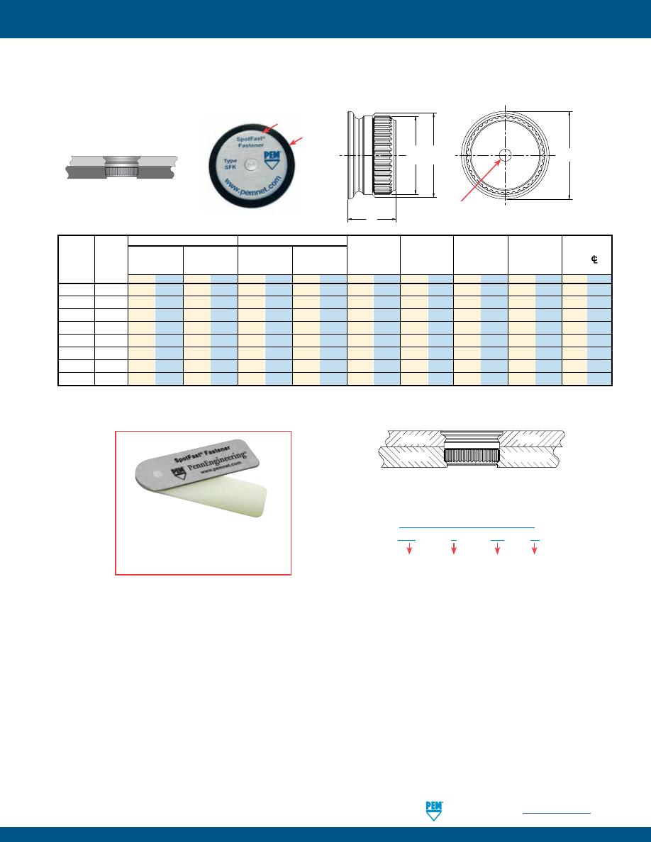
PennEngineering •
www.pemnet.com
K-13
FASTENERS FOR USE WITH PC BOARDS
SFK™ SpotFast® CLINCH/BROACH MOUNT FASTENERS
(1) Fastener will provide flush application at minimum sheet thickness.
Patented.
Panel 1
Panel 2
Metal
PCB/plastic
Type SFK joining metal to PCB/plastic.
Panel 1
Panel 2
Type
Thickness
Mounting Hole
Thickness
Mounting Hole
C
2
Min. Dist
and
Thickness
±0.08 mm /
+0.08 mm /
Min.
+0.08 mm /
C
1
±0.08 mm /
E
L
Hole
C/L
Size
Code
±.003”
+.003” –.000”
(1)
+.003” –.000”
Max.
±.003”
Max.
Max.
To Edge
mm in. mm in. mm in. mm in. mm in. mm in. mm in. mm in. mm in.
SFK-3
0.8
0.8 .031 3
.118 1.6 .063 2.5 .098 2.98 .117 2.9 .114 3.53 .139 2.31 .091 3 0.12
SFK-3
1.0
1 .039 3
.118 1.6 .063 2.5 .098 2.98 .117 2.9 .114 3.76 .148 2.51 .099 3 0.12
SFK-3
1.2
1.2 .047 3
.118 1.6 .063 2.5 .098 2.98 .117 2.9 .114 3.76 .148 2.72 .107 3 0.12
SFK-3 1.6 1.6 .063 3 .118 1.6 .063 2.5 .098 2.98 .117 2.9 .114 3.76 .148 3.12 .123 3 0.12
SFK-5 0.8 0.8 .031 5 .197 1.6 .063 4.5 .177 4.98 .196 4.9 .193 5.56 .219 2.31 .091 5.1 0.20
SFK-5 1.0 1 .039 5 .197 1.6 .063 4.5 .177 4.98 .196 4.9 .193 5.56 .219 2.51 .099 5.1 0.20
SFK-5 1.2 1.2 .047 5 .197 1.6 .063 4.5 .177 4.98 .196 4.9 .193 5.56 .219 2.72 .107 5.1 0.20
SFK-5 1.6 1.6 .063 5 .197 1.6 .063 4.5 .177 4.98 .196 4.9 .193 5.56 .219 3.12 .123 5.1 0.20
Metal
Plastic
Can be used as a single flush-mounted
pivot point. For more information, please
contact our Applications Engineering
Department.
SFK – 3 – 0.8 – ZI
Type
PART NUMBER DESIGNATION
Finish
Panel 1
Mounting
Hole Code
Thickness
Code
C
2
C
1
L
E
PEM® Dimple
(Registered Trademark)
pem-html.html
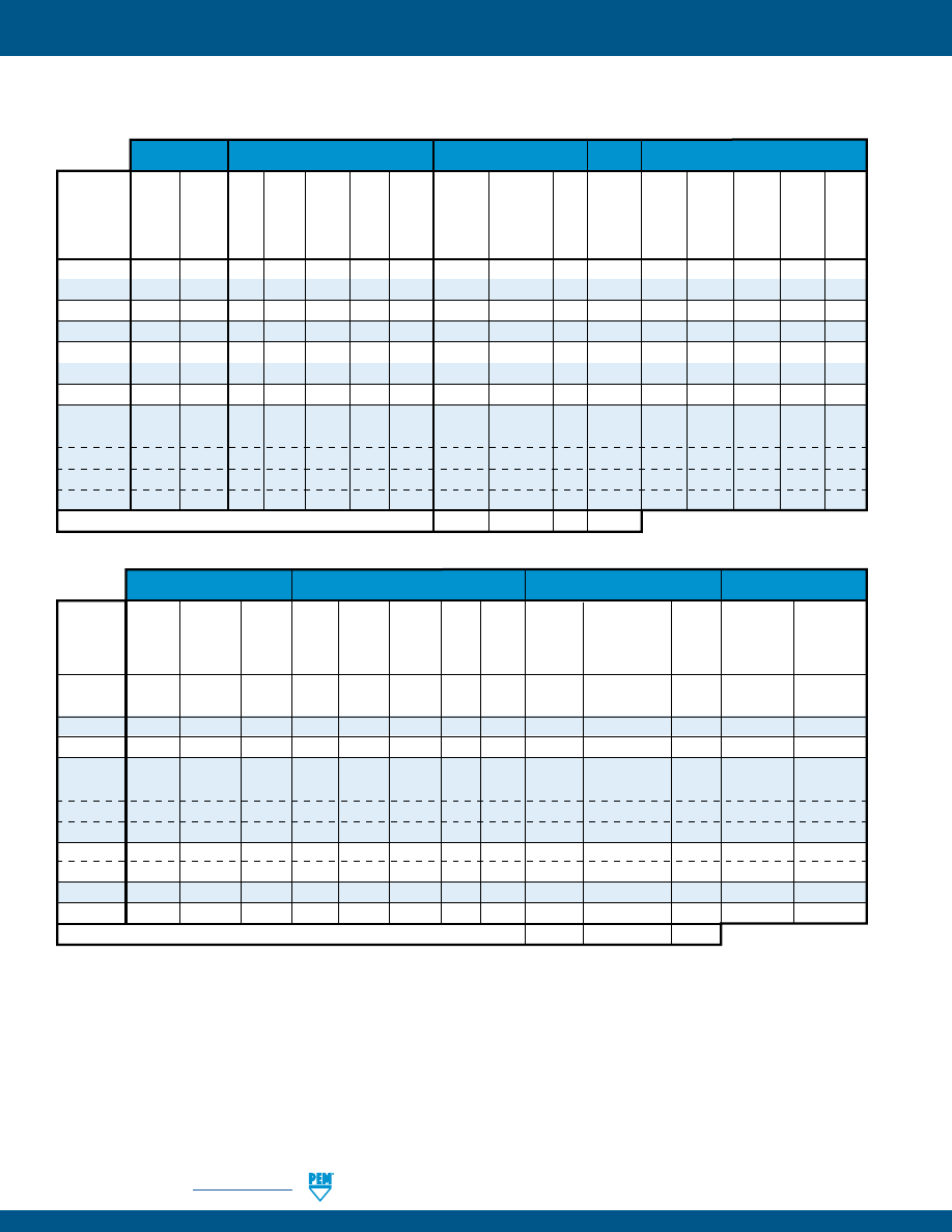
K-14
PennEngineering •
www.pemnet.com
FASTENERS FOR USE WITH PC BOARDS
Optional
Threads (1)
Fastener Materials
Standard Finishes
Finish
For Use in Sheet Hardness: (3)
Electro-Plated
Tin
ASTM
Internal,
External,
Nylon,
B 545, Class B
ASME
ASME
300
Temp.
Passivated
With Clear
B1.1 2B/
B1.1 2A/
Series
CDA-510
Limit
and/or
Preservative
HRB 70 /
HRB 65 /
HRB 60 /
HRB 55 /
ASME
ASME
Carbon Stainless Phosphor CDA-353
200˚ F/
Tested Per
Coating,
No
Black
HB 125
HB 116
HB 107
HB 96
PC
Type
B1.13M 6H
B1.13M 6g
Steel
Steel
Bronze
Brass
93˚ C
ASTM A380
annealed (4)
Finish
Nitride
or Less
or Less
or Less
or Less
Board
KF2
• •
• • •
KFS2
• • •
• •
KFE
• •
• • •
KFSE
• • •
• •
KFB3
• •
• • •
KSSB
•
• • •
KFH
• •
• • •
PFK
Retainer
• •
• • •
Screw
• • •
•
Spring
•
Retaining
Ring
•
Part Number Codes For Finishes
None
ET
X
BN
(1) For plated studs, Class 2A/6g, the maximum major and pitch diameter, after plating, may equal basic sizes and can be gauged to Class 3A/6h, per
ASME B1.1 (see notes at end of table C-1) and ASME B1.13M, Section 8, Paragraph 8.2.
(
2) See PEM Technical Support section of our web site for related plating standards and specifications.
(3) HRB - Hardness Rockwell “B” Scale. HB - Hardness Brinell.
(4) Optimal solderability life noted on packaging.
(5) ABS cap on PSHP screw has a temperature limit of 200˚ F / 93˚ C.
MATERIAL AND FINISH SPECIFICATIONS
Threads (1)
Fastener Materials
Standard Finishes (2)
For Use in Sheet Hardness: (3)
Electro-Plated
Internal,
External,
Tin
ASTM
Bright
ASME
ASME
300
B 545, Class A
Nickel
Miniature
B1.1 2B/
B1.1 2A/
Hardened
Series
Zinc Plated
With Clear
Over
HRB 80 /
ISO 1501,
ASME
ASME
Carbon
Carbon
Stainless
Zinc
5µm,
Preservative
Copper
HB 150
P.C.
Type
4H6
B1.13M 6H
B1.13M 6g
Steel
Steel
Steel
Brass
Diecast
Colorless
Coating, annealed (4)
Flash
or less
Board
SMTSO
• •
•
•
•
SMTSOB
•
•
•
•
SMTRA
•
•
•
•
SMTPFLSM
Retainer
•
•
•
Screw
• •
•
Spring
•
PSHP
(5)
•
•
SMTPR
•
•
•
SFK
• •
•
•
SMTSSS
•
•
•
Part Number Codes For Finishes
ZI
ET
CN
S1 to S1.4
0-80 to 8-32
M1.6 to M4
pem-html.html
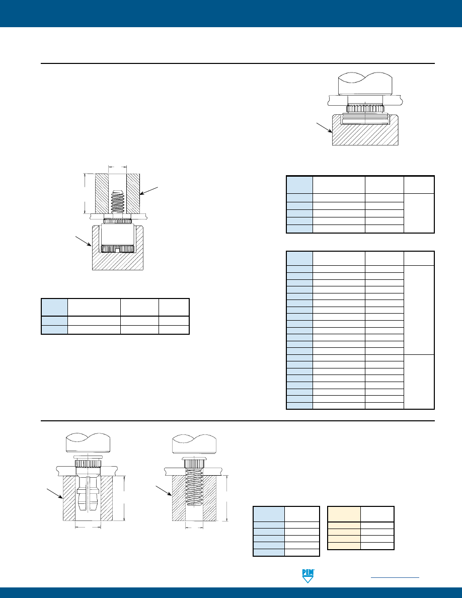
PennEngineering •
www.pemnet.com
K-15
FASTENERS FOR USE WITH PC BOARDS
KSSB™/KFH™ FASTENERS
1.
Prepare properly sized mounting hole in board.
2.
Place fastener into mounting hole as shown.
3.
With installation punch and anvil surfaces parallel,
apply squeezing force until head contacts the board.
PUNCH
D
ANVIL
L Min.
KFH
ANVIL
L + .2”/
5.1 mm Min.
PUNCH
KSSB
D
PUNCH
ANVIL
KF2/KFS2/
KFE/KFSE
KF2™/KFS2™/KFE™/KFSE™/ PFK™ FASTENERS
1.
Prepare properly sized mounting hole in board.
2.
Place fastener into the anvil hole and place the mounting
hole over the shank of the fastener as shown in drawing.
3.
With installation punch and anvil surfaces parallel, apply
squeezing force until shoulder contacts the board.
Part
D
Number +.003” –.000”
KFH-440-L
.113”
KFH-632-L
.140”
KFH-832-L
.166”
KFH-032-L
.191”
KSSB-156-L
.216”
Part
D
Number
+0.08mm
KFH-M3-L
3.1mm
KFH-M4-L
4.1mm
KFH-M5-L
5.1mm
KSSB-4mm-L
5.49mm
INSTALLATION
PEMSERTER® Installation Tooling
Thread
Anvil Part
Punch Part
Type
Code
Number
Number
KF2/KFS2 080
8015899
KF2/KFS2 256/440/M2/M2.5/M3 975200904300
KF2/KFS2
632/M3.5
975200035
975200048
KF2/KFS2
832/M4
975200037
KF2/KFS2
032/M5
975200905300
PEMSERTER® Installation Tooling
Thread
Anvil Part
Punch Part
Type
Code
Number Number
KFE/KFSE
440/116 -4 to -8
975200846300
KFE/KFSE
440/116 -10 to -12
975200847300
KFE/KFSE
440/116 -16 to -20
975200848300
KFE/KFSE
440/116 -20 to -24
975200882300
KFE/KFSE
M3 -3 to -6
975200846300
KFE/KFSE
M3 -8 to -10
975200847300
KFE/KFSE
M3 -12 to -14
975201222300
975200048
KFE/KFSE
M3 -14 to -16
975200848300
KFE/KFSE
632/143 -4 to -8
975200849300
KFE/KFSE
632/143 -10 to -12
975200850300
KFE/KFSE
632/143 -16 to -20
975200851300
KFE/KFSE
632/143 -22 to -24
975200883300
KFE/KFSE
632/143 -28 to -32
975200884300
KFE/KFSE
3.6 -3 to -6
975200849300
KFE/KFSE
3.6 -8 to -10
975200850300
KFE/KFSE
3.6 -12 to -16
975200851300
KFE/KFSE
4.2 -2
975201216300
975200048
KFE/KFSE
4.2 -3 to -6
975201217300
KFE/KFSE
4.2 -8 to -10
975201218300
KFE/KFSE
4.2 -12 to -14
975201220300
KFE/KFSE
4.2 -14 to -16
975201219300
ANVIL
PUNCH
PFK
Thread Dia. +.080”/2mm
Max. Screw
Extension
PEMSERTER® Installation Tooling
Thread
Anvil Part
Punch Part
Type
Code
Number
Number
PFK
440/M3
975200026 975200060
PFK
632
975200027 975200061
PEMSERTER® Installation Tooling
pem-html.html
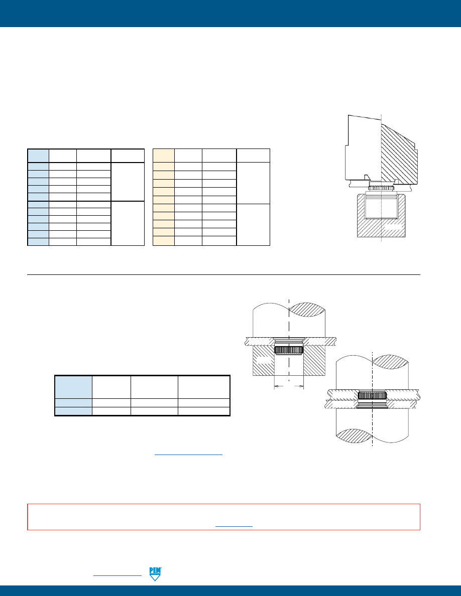
K-16
PennEngineering •
www.pemnet.com
FASTENERS FOR USE WITH PC BOARDS
(1) PennEngineering manufactures and stocks the installation tooling for KFB3 fasteners.
KFB3™ FASTENERS
1.
Punch or drill properly sized round mounting hole in board.
2.
Place fastener into the anvil hole and place the mounting hole over the shank of the fastener
as shown in diagram to the left.
3.
Using a punch flaring tool and a recessed anvil, apply squeezing force until the shoulder of
the fastener contacts the board. As the fastener seats itself in the proper position, the punch
tool will flare the extended portion of the shank outward to complete the installation. The
combination of broaching and flaring provides high pushout performance.
Thread
Length
Anvil Punch
Code
Code
(Flaring Tool)
#4-40
-2
975201213300
#4-40
-4 to -8
975200846300
#4-40
-10 to -12
975200847300
975201231400
#4-40
-16 to -20
975200848300
#4-40
-20 to -24
975200882300
#6-32
-2
975201215300
#6-32
-4 to -8
975200849300
#6-32
-10 to -12
975200850300
975201232400
#6-32
-16 to -20
975200851300
#6-32
-22 to -24
975200883300
#6-32
-28 to -32
975200884300
Thread Length
Anvil Punch
Code
Code
(Flaring Tool)
M3
-2
975201213300
M3
-3 to -6
975200846300
M3
-8 to -10
975200847300
975201231400
M3
-12 to -14
975201222300
M3
-14 to -16
975200848300
M4
-2
975201216300
M4
-3 to -6
975201217300
M4
-8 to -10
975201218300
975201221400
M4
-12 to -14
975201220300
M4
-14 to -16
975201219300
ANVIL
PUNCH
KFB3
AFTER
BEFORE
SFK™ FASTENERS
Step 1.
Prepare properly sized mounting hole in both panels.
Step 2.
Using only Panel 1, with the punch and anvil surfaces
parallel, apply squeezing force until the fastener is flush with
the top of Panel 1.
Step 3.
Place Panel 2 over fastener and apply squeezing force.
Step 2
C
Panel 1
Metal
Punch
Anvil
Step 3
Punch
Anvil
Panel 1
Metal
Panel 2
PCB/plastic
NOTE:
Fastener can be installed in both sheets at once when metal panel is adequately soft
compared to the non-metal panel. E-mail
techsupport@pemnet.com
for more information.
C
Size
±0.13/±.003 Punch
Anvil
(mm) / (in.)
Part No.
Part No.*
SFK-3
3.05 / .120
975200048
970200229300
SFK-5
5.05 / .199
975200048
970200020300
* Part number for anvil used in Step 2
PEMSERTER® Installation Tooling
(1)
PEMSERTER® Installation Tooling
(1)
INSTALLATION NOTES
•
For best results we recommend using a PEMSERTER® press for installation of PEM self-clinching fasteners. Please check our website for more information.
•
Visit the Animation Library on our website to view the installation process
for this product
.
pem-html.html
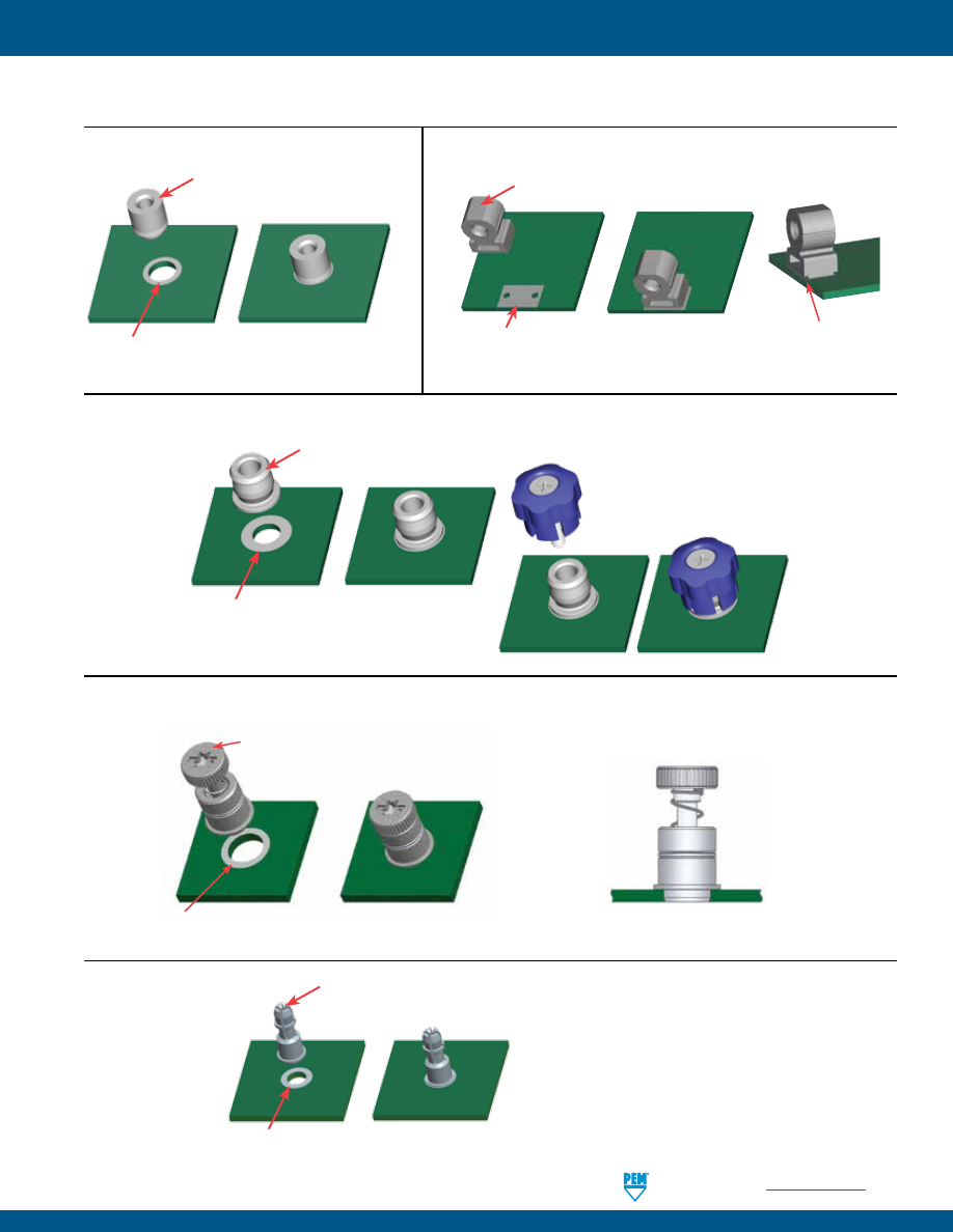
PennEngineering •
www.pemnet.com
K-17
FASTENERS FOR USE WITH PC BOARDS
Solder paste applied
to pad on PCB.
Solder fastener in place
using standard surface
mount techniques.
Polyimide patch applied here for
vacuum pick up.
Solder paste applied to
pad on PCB.
Solder fastener in place
using standard surface
mount techniques.
Screw snapped in place.
Polyimide patch applied
here for vacuum pick up.
Solder paste applied to
pad on PCB.
Solder fastener in place
using standard surface
mount techniques.
Undercut to accept
solder fillet and permit
flush to edge installation.
Flat top for vacuum pick up.
SMT NUTS AND STANDOFFS
SMT CAPTIVE PANEL SCREWS
SMT R’ANGLE® FASTENERS
INSTALLATION
Installs in retracted/unfastened position
SMTPFLSM™ CAPTIVE PANEL SCREWS
Solder paste applied to
pad on PCB.
Polyimide patch applied here
for vacuum pick up.
Solder fastener in place using
standard surface mount techniques.
SMTSS™ FASTENERS
Solder paste applied
to pad on PCB.
Solder fastener in place using standard
surface mount techniques.
Polyimide patch applied here for
vacuum pick up.
pem-html.html
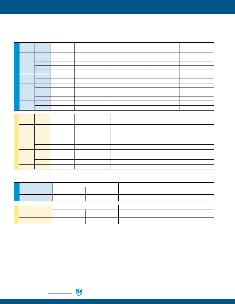
K-18
PennEngineering •
www.pemnet.com
FASTENERS FOR USE WITH PC BOARDS
U
NIF
IE
D
Panel 1 (.060” FR-4 Panel) (4)
Panel 2 (Removable) (4)
Type
Installation
Pushout
Max. First On
Min. First Off
Min. 15th Off
(lbs.)
(lbs.)
Force (lbs.)
Force (lbs.)
Force (lbs.)
KSSB 500 110 13 3.0 1.0
(1) Published installation forces are for general reference. Actual set-up and confirmation of complete installation should be made by observing
proper seating of fastener as described in the installation steps. Other performance values reported are averages when all proper
installation parameters and procedures are followed. Variations in mounting hole size, sheet material, and installation procedure may affect
performance. Performance testing this product in your application is recommended. We will be happy to provide technical assistance and/
or samples for this purpose.
(2) These are typical values for parts installed in drilled mounting holes. Punched mounting holes yield values approximately 15% less.
(3) Not applicable.
(4) See Application Data drawing on page 8.
ME
TR
IC
Panel 1 (1.5 mm FR-4 Panel) (4)
Panel 2 (Removable) (4)
Type
Installation
Pushout
Max. First On
Min. First Off
Min. 15th Off
(kN)
(N)
Force (N)
Force (N)
Force (N)
KSSB
2.2
484
57.7
13.3
4.4
KSSB™ BROACHING SNAP-TOP® STANDOFFS
U
NIF
IE
D
Max. Nut
Test Sheet Thickness
Pushout
Type
Thread
Tightening Torque
&
Installation (lbs.) Torque-out
Code
(in. lbs.)
Test Sheet Material
(lbs.) (2) (in. lbs.)
KF2
256 (3) .060” FR-4 Panel 400
60
6
KFS2
440
(3)
.060” FR-4 Panel 400
65
15
KFE
632
(3)
.060” FR-4 Panel 500
80
30
KFSE
832
(3)
.060” FR-4 Panel 700
95
35
032
(3)
.060” FR-4 Panel 700
100
40
KFB3
440
(3)
.060” FR-4 Panel 1,000
140
18
632
(3)
.060” FR-4 Panel 1,500
170
28
440
4
.060” FR-4 Panel 400
65
7
632
8
.060” FR-4 Panel 400
70
11
KFH
832
15
.060” FR-4 Panel 400
80
16
032
18
.060” FR-4 Panel 400
90
17
PFK
440
(3)
.060” FR-4 Panel 250
55
(3)
632
(3)
.060” FR-4 Panel 400
60
(3)
ME
TR
IC
Max. Nut
Test Sheet Thickness
Pushout
Type
Thread
Tightening Torque
&
Installation (N) Torque-out
Code
(N•m)
Test Sheet Material
(kN) (2) (N•m)
KF2
M3
(3)
1.5
mm FR-4 Panel 2.2
290
1.7
KFS2
M4
(3)
1.5
mm FR-4 Panel 2.2
420
3.4
KFE
M5
(3)
1.5
mm FR-4 Panel 2.9
440
4.5
KFSE
M3
(3)
1.5
mm FR-4 Panel 4.4
560
2.03
KFB3
M4
(3)
1.5
mm FR-4 Panel 6
680
3.2
M3
0.45
1.5
mm FR-4 Panel 1.8
285
0.79
KFH
M4
1.6
1.5
mm FR-4 Panel 1.8
355
1.8
M5
2.1
1.5
mm FR-4 Panel 1.8
400
1.92
PFK
M3
(3)
1.5
mm FR-4 Panel 1.1
245
(3)
KF2™/KFS2™/KFE™/KFSE™/KFB3™/KFH™/PFK™ BROACHING AND BROACH/FLARE MOUNT FASTENERS
PERFORMANCE DATA
(1)
pem-html.html
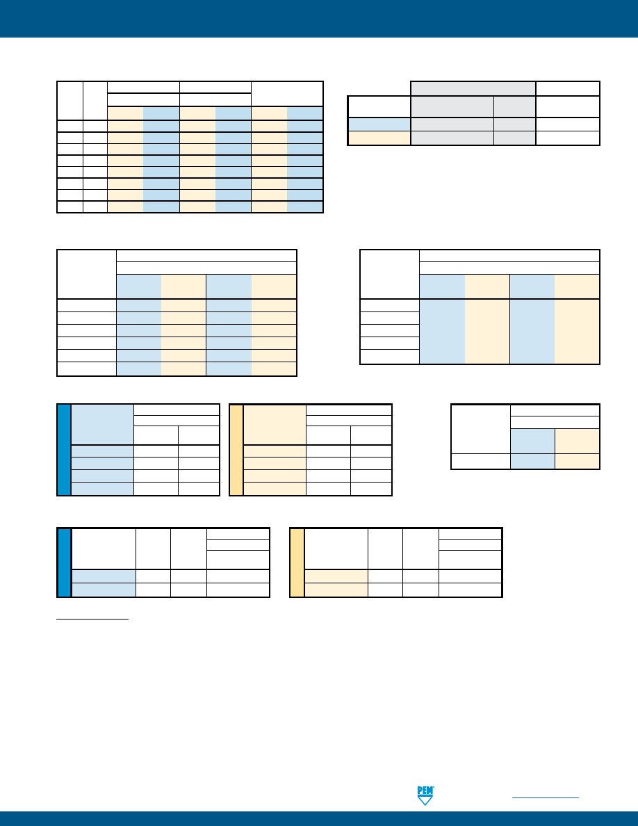
PennEngineering •
www.pemnet.com
K-19
FASTENERS FOR USE WITH PC BOARDS
ME
TR
IC
U
NIF
IE
D
SFK™ SpotFast® CLINCH/BROACH MOUNT FASTENERS
SMTSO™ NUTS AND SPACERS/STANDOFFS
(1)(2)
(1) With lead-free paste. Average values of 30 test points. The data presented here is for general comparison purposes only. Actual performance is
dependent upon application variables. We will be happy to provide samples for you to install. If required, we can also test your installed hardware and
provide you with the performance data specific to your application.
(2) Further testing details can be found in our website’s literature section.
(3) In most applications, pullout strength of the SFK fastener in Panel 1 exceeds pushout strength of Panel 2.
(4) Torque values shown will produce a preload of 70% minimum tensile with a nut factor “k” equal to .1.
(5) Failure occurred at the solder joint. Screw retention strength is greater than the retainer.
SMTSO™ microPEM® FASTENERS
(1)(2)
SMTPR™ RETAINERS
(1)
SMTRA™ R’ANGLE® FASTENERS
(1)(2)
Test Sheet Material
Part .062” Single Layer FR-4
Number
Pushout Pushout
(lbs.) (N)
SMTPR-6-1ET 161.4 718
U
NIF
IE
D
Test Sheet Material
.062” Single Layer FR-4
Part
Pushout
Side Load
Number
(lbs.) (lbs.)
SMTRA256-8-6
51.7
7.1
SMTRA440-9-6
89.5
10.8
SMTRA632-10-8
110.3
8.4
SMTRA832-12-9
137.2
21.2
ME
TR
IC
Test Sheet Material
1.58mm Single Layer FR-4
Part
Pushout
Side Load
Number
(N)
(N)
SMTRAM2-6-5
418.2
56.8
SMTRAM25-6-5
216.5
36.9
SMTRAM3-7-5
257.6
41.3
SMTRAM4-9-7
369.3
73.3
Test Sheet Material
Type
.062” Single Layer FR-4
and Size
Pushout Pushout Torque-out Torque-out
(lbs.)
(N)
(in. lbs.)
(N•m)
SMTSO-080
SMTSO-M1
SMTSO-M1.2
85.1
378.7
4.94
0.56
SMTSO-M1.4
SMTSO-M1.6
Test Sheet Material
Type
.062” Single Layer FR-4
and Size
Pushout Pushout Torque-out Torque-out
(lbs.)
(N)
(in. lbs.)
(N•m)
SMTSO-440 56.5 251 8.56 1
SMTSO-632
93.5
416
13.83
1.6
SMTSO-832
151.1
672
26.96
3
SMTSO-M3
56.5
251
8.56
1
SMTSO-M3.5
93.5
416
13.83
1.6
SMTSO-M4
151.1
672
26.96
3
SMTPFLSM™ FASTENERS
(1)
Min. Rec. Test Sheet Material
Type and
Tensile
Tightening
.060” P.C. Board
Thread Size
Strength
Torque
Pull-off
(lbs.)
(in. lbs.)
(4)
(lbs.)
SMTPFLSM-440 556 4.4
100
SMTPFLSM-632
724
7.0
105
Min. Rec. Test Sheet Material
Type and
Tensile
Tightening
1.5 mm P.C. Board
Thread Size
Strength
Torque
Pull-off
(N) (N•m)
(4)
(N)
SMTPFLSM-M3 2900 0.61
445
SMTPFLSM-M3.5
3269
0.8
465
(5)
(5)
Type
Thick-
Installation into Panel 1
Installation into Panel 2
Pushout of Panel 2
(3)
and
ness
Cold-rolled Steel
FR-4 Fiberglass
Size Code
kN lbs. kN lbs. N lbs.
SFK-3 0.8
6.2
1400
1.8
400
200
45
SFK-3 1.0
8
1800
1.8
400
200
45
SFK-3 1.2
8.9
2000
1.8
400
200
45
SFK-3 1.6 10.2 2300
1.8
400
200
45
SFK-5 0.8
11.1
2500
1.8
400
400
90
SFK-5 1.0
13.5
3000
1.8
400
400
90
SFK-5 1.2
15.6
3500
1.8
400
400
90
SFK-5 1.6
17.8
4000
1.8
400
400
90
TESTING CONDITIONS
Oven
Quad ZCR convection oven w/ 4 zones
Spokes
2 Spoke Pattern
High Temp
473˚F / 245˚C
Paste
Amtech NC559LF Sn96.5/3.0Ag/0.5Cu (SAC305)
(SMTSO, SMTRA, SMTPR)
Board Finish
62% Sn, 38% Pb
Alpha CVP-390 Sn96.5/3.0Ag/0.5Cu (SAC305)
(SMTPFLSM, SMTSS)
Screen Printer
Ragin Manual Printer
Stencil
.0067” / 0.17 mm thick
(SMTSO, SMTRA, SMTPR, SMTSS)
Vias
None
.005” / 0.13 mm thick
(SMTPFLSM)
SMTSS™ ReelFast® SNAP-TOP® STANDOFFS
(1)(2)
Type, Material
Test Sheet Material
Pushout
Max. Snap-on Force
and Size
SMTSSS-156
.062" Single Layer FR-4
113 lbs.
20 lbs.
SMTSSS-4MM
1.58 mm Single Layer FR-4
500 N
89 N
Panel 1 (Bottom)
Panel 2 (Top)
pem-html.html
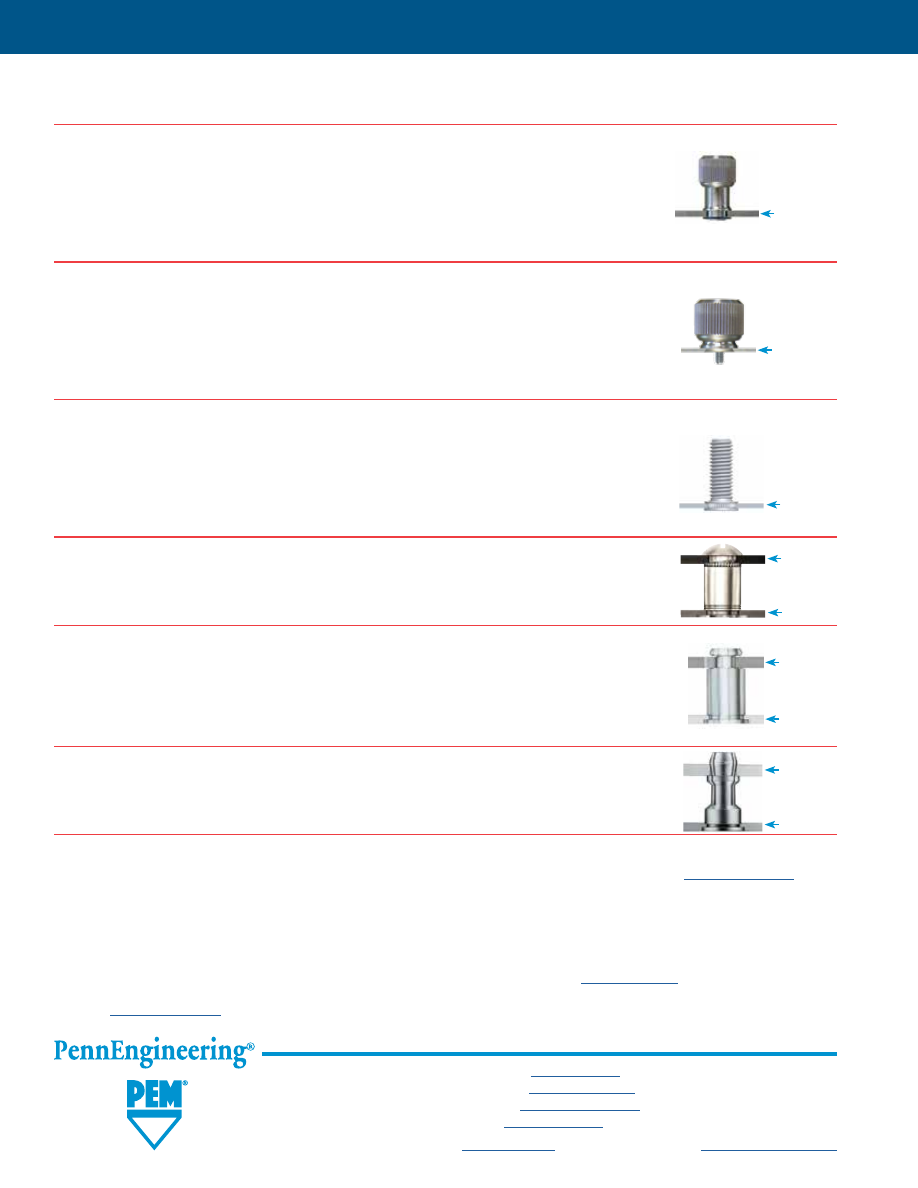
K-20
For more information on these and other PEM products, visit our PEMNET™ Resource Center at
www.pemnet.com
PF11MW™ FLOATING CAPTIVE PANEL SCREWS
(See PEM® Bulletin PF)
Unique flare mount feature allow fasteners to “float” in mounting hole.
•
Compensates for mating thread misalignment.
•
Installs into any panel material.
•
Appropriate for close center-line-to-edge applications.
•
Color coded knobs available.
PF11MF™ FLARE-MOUNTED CAPTIVE PANEL SCREWS
(See PEM® Bulletin PF)
•
Appropriate for close centerline-to-edge applications.
•
Doesn’t require high installation force.
•
Installs into any panel material.
•
Installs flush on back side of panel.
•
Color coded knobs available.
SGPC™ SWAGING COLLAR STUDS
(See PEM® Bulletin FH)
•
Can be installed into most materials, including stainless steel and rigid non-metallic panels.
•
Can be used to attach dissimilar materials.
•
Can accommodate multiple panels as long as the total thickness does not exceed the
maximum sheet thickness.
•
Appropriate for close center-line-to-edge applications.
SOAG™/SOSG™ GROUNDING STANDOFFS
(See PEM® Bulletin SO)
•
Designed for clinching into steel or aluminum chassis.
•
“Gripping teeth” on opposite side of standoff makes firm electrical contact with mating PC Board.
SKC™ KEYHOLE® STANDOFFS
(See PEM® Bulletin SK)
•
Clinch feature mounts fastener permanently into metal sheet.
•
Allows for quick attachment and detachment of PC Board.
•
Head is flush or sub-flush in metal sheet.
•
Makes horizontal or vertical component mounting possible.
SSA™/SSC™/SSS™ SNAP-TOP® STANDOFFS
(See PEM® Bulletin SSA)
•
Spring action holds PC Boards and subassemblies securely, while allowing for quick removal.
•
Screws and other threaded hardware are eliminated.
Metal
PC Board
plastic or
metal
Can install
into PC
Board,
plastic
or metal
Metal
PC Board
plastic or
metal
Metal
PC Board
plastic or
metal
OTHER FASTENERS FOR CONSIDERATION TO USE WITH PC BOARDS
Can install
into PC
Board,
plastic
or metal
Can install
into PC
Board,
plastic
or metal
FASTENERS FOR USE WITH PC BOARDS
All PEM® products meet our stringent quality standards. If you require additional industry or other specific
quality certifications
, special procedures and/or part
numbers are required. Please contact your local sales office or representative for further information.
Regulatory
compliance information
is available in Technical Support section of our website. Specifications subject to change without notice. See our website for the
most current version of this bulletin.
North America:
Danboro, Pennsylvania USA
•
E-mail:
info@pemnet.com
•
Tel: +1-215-766-8853
•
800-237-4736 (USA)
Europe:
Galway, Ireland
•
E-mail:
europe@pemnet.com
•
Tel: +353-91-751714
Asia/Pacific:
Singapore
•
E-mail:
singapore@pemnet.com
•
Tel: +65-6-745-0660
Shanghai, China
•
E-mail:
china@pemnet.com
•
Tel: +86-21-5868-3688
Visit our PEMNET™ Resource Center at
www.pemnet.com
•
Technical support e-mail:
techsupport@pemnet.com
pem-html.html
LN
™
SELF-LOCKING
FASTENERS
PEM® self-clinching locknuts prevent
mating hardware from loosening.
Bulletin LN-218
pem-html.html

LN-2
PennEngineering •
www.pemnet.com
SELF-LOCKING FASTENERS
PEM® SELF-CLINCHING LOCKNUTS PREVENT MATING HARDWARE FROM LOOSENING
PEM® self-clinching locknuts provide ideal solutions to prevent mating hardware from loosening in service due to
vibration or other application-related factors. This family of fasteners includes a variety of types and different locking-
feature styles to satisfy a wide range of applications. Their use can save time and money compared with alternative
chemical locking methods or patches.
ABOUT LOCKING THREADS
PEM® locknuts include two locking designs:
1) PREVAILING TORQUE
(CFN™, FE™, FEO™, UL™, LAS™, LAC™, LA4™, LK™, LKS™, LKA™, PL™, PLC™ and SL™ locknuts) – a
design feature of the lock nut produces friction between threads of mated components thereby increasing the force
needed to tighten as well as loosen the nut. Prevailing torque locknuts provide essentially the same torque value
regardless of the amount of axial load applied.
Available in two types:
•
All metal –
All PEM metal prevailing torque type locknuts achieve their prevailing torque by altering the shape of the nut
in some way - most commonly by distorting the threads of the nut, which then grips the mating part during
tightening. Screws for use with PEM prevailing torque locknuts should be Class 3A/4h fit or no smaller than
Class 2A/6g.
Available in three styles:
–
Elliptically squeezed threads
(UL™, FE™, FEO™, LAC™, LAS™ and LA4™ locknuts) – the thread barrel is slightly
deformed into an elliptical shape.
–
Flexing jaws
(LK™, LKS™ and LKA™ locknuts) - the thread barrel is vertically slit and then the two sections are
squeezed together.
–
One or two deformed threads
(SL™ locknuts) - the last threads on the head side of the nut are deformed.
Typically prevailing torque locknuts utilizing a metal locking feature are treated with a dry film lubricant coating
to afford some level of lubricity to reduce damage to the threads from repeated installation and removal of the
screw and reduce required tightening torque. Care should be taken to be sure that lubricant is not removed in
any post installed finishing operations.
•
Nylon insert
The PL™, PLC™ and CFN™ locknuts use a plastic insert, typically made from nylon to generate the torque
resistance. A nylon ring is attached to the self-clinching body on the screw exit side with an ID approximately at
the screw pitch diameter. As the screw enters this ring, there is interference at the major diameter generating a
prevailing torque. The major advantage of this locking method is the greatly reduced chance of any conductive
debris being generated by repeated installation and removal of the screw.
2) FREE-RUNNING
(S-RT™ locknuts) – a nut that requires tightening against a bearing surface in order for the locking
mechanism to function. If the tightening force (clamp load) is removed for any reason, these nuts no longer provide
any torsional resistance to rotation. The
modified thread formation
allows mating screws to spin freely during the
attachment process until clamp load is induced during the screw-tightening process.
PEM free-running locknuts will accept a maximum material 6g/2A screw.
pem-html.html
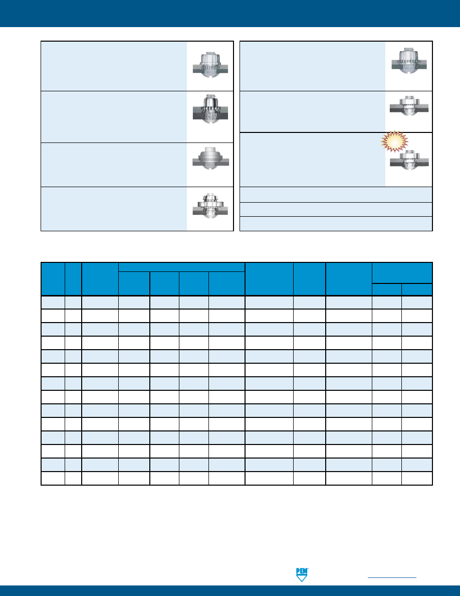
SELF-LOCKING FASTENERS
PennEngineering •
www.pemnet.com
LN-3
CFN™
broaching fasteners are available for
thinner sheet, close-to-edge applications. The
nylon locking element provides prevailing
torque to eliminate loosening of mating
threaded hardware -
PAGE 4
FE™/FEO™/UL™
miniature locking nuts,
provide a smaller body for tight space,
lightweight applications -
PAGE 5
LAS™/LAC™/LA4™
nuts with self-locking,
floating threads that permit up to .030”/0.76
mm adjustment for mating hole misalignment
-
PAGE 6
LK™/LKS™/LKA™
nuts have a rugged
PEMFLEX® self-locking feature
which
meets demanding locking performance
requirements
-
PAGE 7
PL™/PLC™
PEMHEX® nuts with a nylon
hexagonal element provide a locking option
for applications where a metal on metal
locking feature is not desired
-
PAGE 8
SL™
locknuts offer a cost effective TRI-DENT®
locking feature
and effective prevailing locking
torque -
PAGE 9
S-RT™
locknuts are free-running until clamp
load is induced. A modified thread angle on
the loaded flank provides the vibration resistant
locking feature
-
PAGE 10
Material and finish specifications -
PAGES 11
Installation -
PAGES 12 - 15
Performance data -
PAGES 16 - 20
Nylon Insert
Elliptically
Squeezed Threads
Elliptically
Squeezed Threads
Flexing Jaws
Nylon Insert
Deformed Threads
CFN 4
1
• •
(6)
•
FE 5
15
(3)
• •
(7)
•
FEO 5 15
(3)
• •
(7)
•
UL 5
5
(4)
• •
(7)
•
LAS 6
15
(3)
• •
(7)
•
LAC 6
15
(3)
• •
(7)
•
LA4
(2)
6
15
(3)
• •
(7)
•
LK 7
15
(3)
•
(7)
LKS 7
15
(3)
•
(7)
LKA 7
15
(3)
•
(9)
PL 8
15
(3)
(6)
•
PLC 8
15
(3)
(6)
•
SL 9
3
•
(8)
S-RT 10
(5)
•
(8)
LOCKING NUT SELECTOR GUIDE
PEM Page
Locking No.
Nut
Application Features
Locking
Non-metal
Locking
High
Close-to-
Performance
on Metal
Covered by
(1)
Performance Clamp Floating Light
edge
Temperature Locking
Locking
Cycles
Strength Threads Weight Applications
Limit
Feature
Style
M45938/7 M45938/11
(1) To meet national aerospace standards and to obtain testing documentation, product must be ordered using appropriate NASM45938 part number.
Check our web site for a complete Military Specification and National Aerospace Standards Reference Guide (Bulletin NASM).
(2) Specifically designed to be installed into stainless steel sheets.
(3) See page 19 for information on NASM25027 as applied to PEM self-clinching, self-locking nuts.
(4) Meets torque requirements for NASM25027 through five cycles.
(5) Locking performance is not affected by the number of on/off cycles.
(6) Nylon locking element temperature limit is 250˚ F / 120˚ C.
(7) Dry film lubricant rated for use up to 400˚ F / 204˚ C.
(8) The fastening strength of the locknut is maintained up to 800˚ F / 426˚ C. Temperatures above 300˚ F / 149˚ C will dehydrate the conversion coating.
(9) Aluminum material temperature limit is 250˚ F / 120˚ C.
Nylon Insert
Elliptically Squeezed
Elliptically Squeezed
Elliptically Squeezed
Elliptically Squeezed
Elliptically Squeezed
Elliptically Squeezed
Flexing Jaws
Flexing Jaws
Flexing Jaws
Nylon Insert
Nylon Insert
Deformed Threads
Free-running Threads
NEW!
Free-running
Threads
pem-html.html
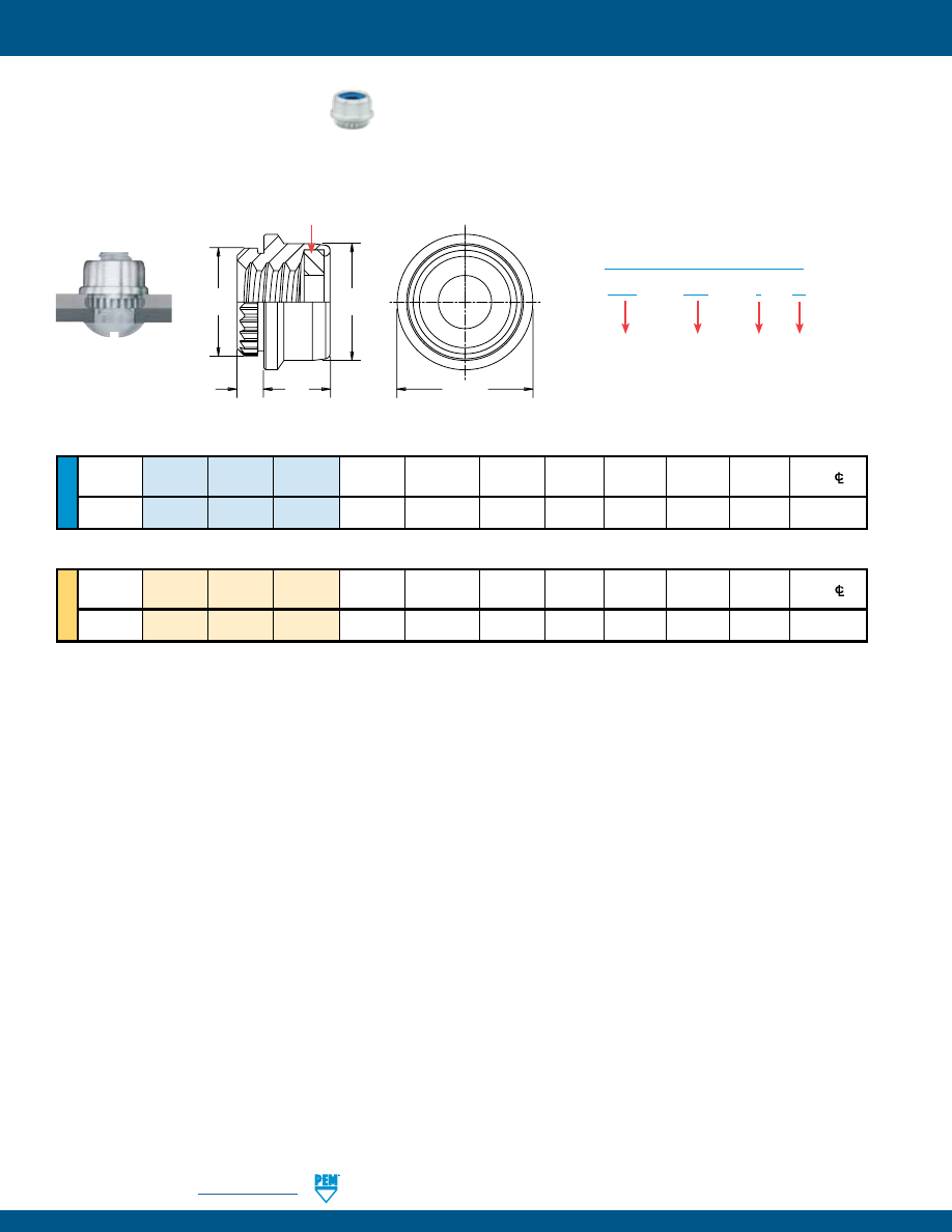
LN-4
PennEngineering •
www.pemnet.com
SELF-LOCKING FASTENERS
ME
TR
IC
U
NIF
IE
D
A Min.
Hole
Size C D E T
Min. Dist.
Thread Type Thread Shank
(Shank)
Sheet
In Sheet
±.002
±.004 +.001 Max. Hole
C/L
Size Code Code
±.003
Thickness
+.003 –.000
–.004
to Edge
.112-40
CFN 440 1 .040 .043 .152 .162 .175 .203 .104 .115
(#4-40)
Thread
A Min.
Hole
Size C D E T
Min. Dist.
Size x
Type
Thread Shank
(Shank)
Sheet
In Sheet
±0.05
±0.1 +0.03 Max. Hole
C/L
Pitch
Code Code
±0.08
Thickness
+0.08
–0.1
to Edge
M3
x 0.5
CFN
M3
1
1.02
1.1
3.86
4.11
4.45
5.16
2.65
2.93
CFN™ BROACHING LOCKNUT
•
For thinner sheets, close-to-edge applications.
•
Prevailing torque locking element provides torque to eliminate loosening of mating threaded hardware.
All dimensions are in inches.
All dimensions are in millimeters.
CFN – 440 – 1
ZI
Finish
Code
PART NUMBER DESIGNATION
Type
Thread
Code
Shank
Code
* PEM Trademark.
D
E
C
A
T
Nylon locking element
(Blue identifier* for unified fasteners / black identifies metric fasteners)
Clinching profile may vary.
pem-html.html
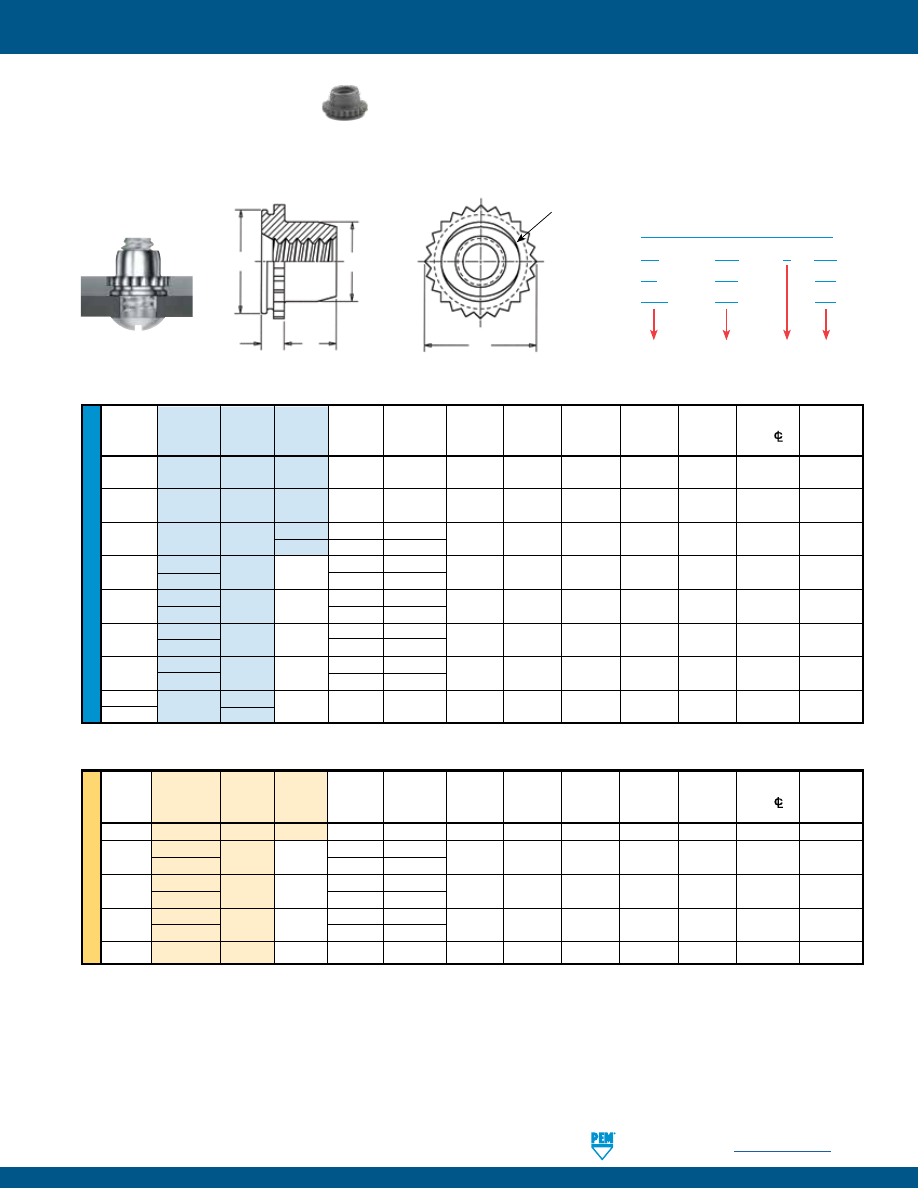
SELF-LOCKING FASTENERS
PennEngineering •
www.pemnet.com
LN-5
ME
TR
IC
U
NIF
IE
D
All dimensions are in inches.
Hole
Size
Min.
Max.
Hole
Shank
A
Sheet
In
Sheet
C T
Dist.
In
Thread Type Thread Code (Shank) Thickness +.003 +.000
D
E
+.015 Hole
/L
Attached
Size Code
(1)
Max.
(2)
–.000
–.005
Max.
±.005
–.000
to Edge
Parts
.060-80
UL
080
0
.020
.019 - .022
.110
.1095
.076
.125
.050
.09
.080
(#0-80)
.073-64
UL
164
0
.020
.019 - .022
.110
.1095
.090
.125
.050
.09
.093
(#1-64)
.086-56
UL 256
0
.020
.019 - .022
.144 .1435 .106 .160 .065
.11 .106
(#2-56)
1
.031
.030 - .036
.112-40 FEO
440
.040
.039 - .045
.172 .171 .145 .192 .065
.14 .132
(#4-40)
FE
.060
.059 - .070
.138-32 FEO
632
.040
.039 - .045
.213 .212 .180 .244 .075
.17 .158
(#6-32)
FE
.060
.059 - .070
.164-32 FEO
832
.040
.039 - .045
.290 .289 .215 .322 .090
.20 .184
(#8-32)
FE
.060
.059 - .070
.190-32 FEO
032
.040
.039 - .045
.290 .289 .245 .322 .110
.20 .210
(#10-32)
FE
.060
.059 - .070
1/4-20
FE
0420
.060
.059 - .070
.344
.343
.318
.384
.120
.28 .270
1/4-28
0428
All dimensions are in millimeters.
Min.
Max.
Hole
Thread
Shank
A
Sheet
Hole
Size
Dist. In
Size x
Type
Thread
Code
(Shank)
Thickness
In Sheet
C
D
E
T
Hole
C/L
Attached
Pitch
Code
(1)
Max.
(2)
+0.08
–0.13
Max.
±0.13
+0.4
to Edge
Parts
M2
x 0.4
UL
M2
1
0.76
0.76 - 0.91
3.61
3.6
2.5
4.07
1.65
2.8
2.5
M3 x 0.5
FEO
M3
1.02
0.99 - 1.14
4.39 4.37 3.96 4.88 1.9
3.6 3.5
FE
1.53
1.5 - 1.78
M4 x 0.7
FEO
M4
1.02
0.99 - 1.14
7.39 7.37 5.23 8.17 2.55
5.2 4.5
FE
1.53
1.5 - 1.78
M5 x 0.8
FEO
M5
1.02
0.99 - 1.14
7.39 7.37 6.48 8.17 3.05
5.2 5.5
FE
1.53
1.5 - 1.78
M6
x 1
FE
M6
1.53
1.5 - 1.78
8.74
8.72
7.72
9.74
3.3
7.1
6.5
(1) Shank code applicable only to UL fasteners.
(2) In applications between the sheet thicknesses for your thread size, see last paragraph of installation data on page 11. Knurled collar may fracture if
fastener is used in sheets thicker than the specified range and the screw is tightened beyond maximum tightening torque.
FE™/FEO™/UL™ LOCKNUTS
•
Strong, knurled collar guarantees against rotation of the fastener in the sheet.
•
The torque-out resistance of the embedded knurl greatly exceeds the torque that can be exerted by the self-locking feature.
UL –
080 – 0
CW
FE –
440 – MD
FEO – 440 – MD
Finish
Code
PART NUMBER DESIGNATION
Type
Thread
Code
Shank
Code
C
D
E
A
T
Tops
elliptically
squeezed
Clinching profile may vary.
pem-html.html
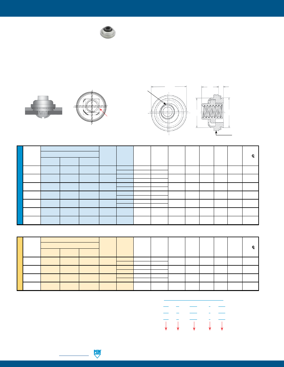
LN-6
PennEngineering •
www.pemnet.com
SELF-LOCKING FASTENERS
U
NIF
IE
D
Type
Hole
Thread
Thread
Shank
A
Min.
Size
in
C
D
E
T
2
Min. Dist.
Size
Fastener Material
Code Code (shank) Sheet Sheet Max. Max. ±.015 Max. Hole
C/
300 Series
400 Series
Max.
Thickness
+.003
to Edge
Steel
Stainless
Stainless –.000
.112-40
LAS LAC LA4 440
1 .038 .038
.290 .289 .290 .360 .190 .30
(#4-40)
2
(1)
.054 .054
.138-32
LAS LAC LA4 632
1 .038 .038
.328 .327 .335 .390 .200 .32
(#6-32)
2
(1)
.054 .054
.164-32
LAS LAC LA4 832
1 .038 .038
.368 .367 .365 .440 .210 .34
(#8-32)
2
(1)
.054 .054
.190-24
LAS LAC LA4 024 1 .038 .038 .406 .405 .405 .470 .270 .36
(#10-24)
2
.054
.054
.190-32
LAS LAC LA4 032 1 .038 .038 .406 .405 .405 .470 .270 .36
(#10-32)
2
(1)
.054 .054
.250-20
LAS
LAC
–
0420 2
.054 .054 .515 .514 .510 .600 .310 .42
(1/4-20)
.250-28
LAS
LAC
–
0428 2
.054 .054 .515 .514 .510 .600 .310 .42
(1/4-28)
All dimensions are in inches.
LAS™/LAC™/LA4™ LOCKNUTS
•
Provide load-bearing threads in thin sheets and permit a minimum of .030”/0.76 mm adjustment for mating hole misalignment.
•
Extra strength and support in assembly is obtained by the threads of the floating nut extending into the retainer shank.
•
Thread locking torque performance is equivalent to applicable NASM25027 specifications.
•
LA4 floating fasteners are specifically designed to be installed into stainless steel sheets.
To meet national aerospace standards and to obtain testing documentation, product must be ordered to US NASM45938/11 specifications. Check
our web site for a complete Military Specification and National Aerospace Standards Reference Guide (Bulletin NASM)
(1) This shank code is not available for LA4 nuts.
ME
TR
IC
Type
Hole
Thread
Thread
Shank
A
Min.
Size
in
C
D
E
T
2
Min.
Dist.
Size x
Fastener Material
Code Code (shank) Sheet Sheet Max. Max. ±0.38 Max. Hole
CL
Pitch
300 Series
400 Series
Max.
Thickness
+0.08
to Edge
Steel
Stainless
Stainless
M3 x 0.5
LAS
LAC
LA4
M3
1 0.97 0.97
7.37 7.35 7.37 9.14 4.83 7.62
2
(1)
1.38 1.38
M4 x 0.7
LAS
LAC
LA4
M4
1 0.97 0.97
9.35 9.33 9.28 11.18 5.34 8.64
2
(1)
1.38 1.38
M5 x 0.8
LAS
LAC
LA4
M5
1 0.97 0.97
10.29 10.29 10.29 11.94 6.86 9.14
2
(1)
1.38 1.38
M6 x 1
LAS
LAC
–
M6
2
1.38
1.38
13.08
13.06
12.96
15.24
7.88
10.67
All dimensions are in millimeters.
Type
LA
C – 440 – 1
MD
LA
S – 440 – 1
MD
LA
4 – 440 – 1
MD
Shank
Code
Thread
Code
Finish
Code
Retainer
Material
Code
PART NUMBER DESIGNATION
D
C
Threaded Top
Elliptically
Formed
A
T
E
Single groove
identifier on
LA4 nuts
Clinching profile may vary.
Float –
.015”/0.38 mm minimum,
in all directions from center,
.030”/0.76 mm total.
PEM® Double Squares are a
registered trademark.
pem-html.html
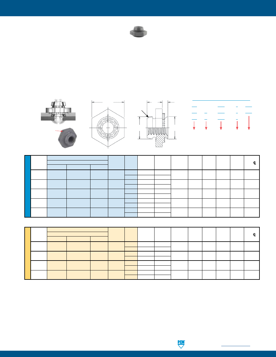
SELF-LOCKING FASTENERS
PennEngineering •
www.pemnet.com
LN-7
LK™/LKS™/LKA™ PEMFLEX® LOCKNUTS
The PEM design utilizes two rugged, semicircular flexing jaws instead of several less-supported segments. The greater ruggedness and
retention of this PEMFLEX® action prevents relaxation and loosening of the fastener in severe service. This design also protects the screw
threads. Clearances obtained by only two interruptions of a full circumference, together with the spreading of the jaws by the entering
screw, minimize the possibility of thread damage.
•
Hex shoulder provides increased pull-through performance and a positive stop during installation.
•
The flexing action of locking feature permits repeated use and effective locking torque.
•
Thread locking performance of LK and LKS fasteners (with MD finish) and LKA fasteners (lubricated) are equivalent to applicable
NASM25027 specifications.
ME
TR
IC
U
NIF
IE
D
Thread
Type A
Hole Size Min. Dist.
Size x
Thread Shank (Shank)
Min. Sheet
In Sheet
C D E T
Hole
C/L
Pitch
Fastener Material
Code Code Max. Thickness +0.08 Max. Max. Nom. ±0.25 to Edge
Carbon Steel
Stainless Steel
Aluminum
M2.5 X 0.45 LK
LKS
LKA M2.5
1 0.97 1
4.37 4.35 4.45 6.35 3.43 3.9
2 1.38 1.4
M3 X 0.5
LK
LKS
LKA
M3
1 0.97 1
4.75 4.73 4.85 6.35 3.43 4
2 1.38 1.4
M4 X 0.7
LK
LKS
LKA
M4
1 0.97 1
6.76 6.73 6.2 8.73 4.45 5.2
2 1.38 1.4
M5 X 0.8
LK
LKS
LKA
M5
1 0.97 1
7.92 7.9 7.4 9.53 5.21 5.6
2 1.38 1.4
Type A
Hole Size
Min. Dist.
Thread
Thread Shank (Shank)
Min. Sheet
In Sheet
C D E T
Hole
C/L
Size
Fastener Material
Code Code Max. Thickness +.003 Max. Max. Nom. ±.010 to Edge
Carbon Steel
Stainless Steel
Aluminum
-.000
.086-56
LK
LKS LKA 256
1 .038 .040
.172 .171 .165 .250 .135 .156
(#2-56)
2 .054 .056
.112-40
LK
LKS LKA 440
1 .038 .040
.187 .186 .185 .250 .135 .156
(#4-40)
2 .054 .056
.138-32
LK
LKS LKA 632
1 .038 .040
.219 .218 .220 .312 .145 .187
(#6-32)
2 .054 .056
.164-32
LK
LKS LKA 832
1 .038 .040
.266 .265 .250 .343 .175 .203
(#8-32)
2 .054 .056
.190-32
LK
LKS LKA 032
1 .038 .040
.312 .311 .285 .375 .205 .218
(#10-32)
2 .054 .056
All dimensions are in inches.
All dimensions are in millimeters.
Grooves
indicate
metric part
Type
LK – 632 – 1
MD
LK
S – 632 – 1
MD
LK
A – 632 – 1
Shank
Code
Thread
Size
Code
Finish
Code
Fastener
Material
Code
PART NUMBER DESIGNATION
E
T
D
C
A
Flexing
jaws
Clinching profile may vary.
pem-html.html
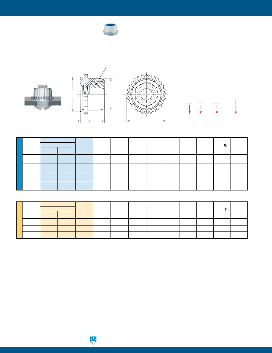
LN-8
PennEngineering •
www.pemnet.com
SELF-LOCKING FASTENERS
ME
TR
IC
U
NIF
IE
D
All dimensions are in inches.
Thread
Type
A
Sheet
Hole Size
Min. Dist. Max.
Size x Fastener Material
Thread
(Shank)
Thickness
In Sheet
C
D
E
T
Hole
C/L
Hole In
Pitch
Steel Stainless
Code
Max.
(1) (2)
+0.08
Max.
Max.
Max.
Max.
to Edge Attached
Steel
Parts
M3
x 0.5
PL
PLC
M3
1.53
1 - 1.78
6
5.98
5.52
7.01
3.56
4.32
3.5
M4
x 0.7
PL
PLC
M4
1.53
1 - 1.78
7.5
7.48
7.01
8.54
4.2
5.59
4.5
M5
x 0.8
PL
PLC
M5
1.53
1 - 1.78
8
7.98
7.52
9
4.45
6.35
5.5
All dimensions are in millimeters.
(1) Can be used in panel thickness of .040” to .060”/1 mm to 1.53 mm provided the fastener is not fully installed. The knurled collar must be left protruding
above the sheet to the degree that the sheet thickness is less than .060”/1.53 mm. See installation instructions.
(2) Knurled collar may fracture if fastener is used in sheets thicker than .070”/1.78 mm and screw is tightened beyond maximum tightening torque.
* PEM Trademark.
Type
A
Sheet
Hole Size
Min. Dist. Max.
Thread Fastener Material
Thread
(Shank)
Thickness
In Sheet
C
D
E
T
Hole
C/L
Hole In
Size
Steel
Stainless Code Max.
(1) (2)
+.003 –.000
Max.
Max.
Max.
Max.
to Edge Attached
Steel
Parts
.112-40
PL
PLC
440
.060
.040 - .070
.234
.233
.215
.274
.130
.170
.132
(#4-40)
.138-32
PL
PLC
632
.060
.040 - .070
.265
.264
.246
.305
.130
.190
.158
(#6-32)
.164-32
PL
PLC
832
.060
.040 - .070
.297
.296
.278
.338
.155
.220
.184
(#8-32)
.190-32
PL
PLC
032
.060
.040 - .070
.312
.311
.293
.353
.165
.250
.210
(#10-32)
PL™/PLC™ PEMHEX® LOCKNUTS
•
Thread locking torque performance is equivalent to applicable NASM25027 specifications.
•
The strong knurled collar receives the installation force and resists torque.
•
The spin resistance of the knurl greatly exceeds the torque that can be exerted by the self-locking feature.
Finish
Code
PART NUMBER DESIGNATION
Type
Thread
Code
Material
Code
PL – 440 – ZI
PL
C – 440
D
E
C
A
T
Nylon locking element
(Blue identifier* for unified fasteners / black identifies metric fasteners)
Clinching profile may vary.
pem-html.html
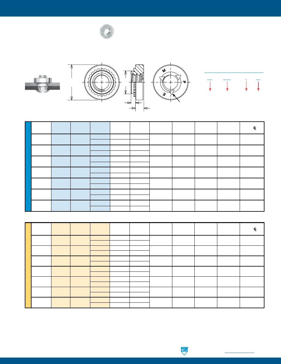
SELF-LOCKING FASTENERS
PennEngineering •
www.pemnet.com
LN-9
ME
TR
IC
U
NIF
IE
D
A
Hole Size
Min. Dist.
Thread
Type
Thread
Shank
(Shank)
Min. Sheet
In Sheet C
E T Hole
C/L
Size
Code
Code
Max.
Thickness +.003 –.000
Max.
±.010
±.010
to Edge
.112-40
SL 440
1 .038 .040
.166 .165 .250 .070 .19
(#4-40)
2 .054 .056
.138-32
SL 632
1 .038 .040
.1875 .187 .280 .070 .22
(#6-32)
2 .054 .056
.164-32
SL 832
1 .038 .040
.213 .212 .310 .090 .27
(#8-32)
2 .054 .056
.190-32
SL 032
1 .038 .040
.250 .249 .340 .090 .28
(#10-32)
2 .054 .056
.250-20
SL 0420
1 .054 .056
.344 .343 .440 .170 .34
(1/4-20)
2 .087 .091
.313-18
SL 0518
1 .054 .056
.413 .412 .500 .230 .38
(5/16-18) 2 .087 .091
.375-16
SL 0616
1 .087 .090
.500 .499 .625 .270 .44
(3/8-16) 2 .120 .125
Thread
A
Hole Size
Min. Dist
Size x
Thread
Shank
(Shank)
Min. Sheet
In Sheet
C
E
T
Hole
C/L
Pitch
Type
Code
Code
Max.
Thickness
+0.08
Max.
±0.25
±0.25
to Edge
1 0.98 1
M3 x 0.5 SL M3
2 1.38 1.4
4.22 4.2 6.35 1.5 4.8
1 0.98 1
M3.5 x 0.6 SL M3.5
2 1.38 1.4
4.75 4.73 7.11 1.5 5.6
1 0.98 1
M4 x 0.7 SL M4
2 1.38 1.4
5.41 5.38 7.87 2 6.9
1 0.98 1
M5 x 0.8 SL M5
2 1.38 1.4
6.35 6.33 8.64 2 7.1
1 1.38 1.4
M6 x 1 SL M6
2 2.21 2.3
8.75 8.73 11.18 4.08 8.6
M8 x 1.25
SL
M8
1 1.38 1.4
10.5 10.47 12.7 5.47 9.7
2 2.21 2.3
M10 x 1.5
SL
M10
1 2.21 2.29
14 13.97 17.35 7.48 13.5
2 3.05 3.18
(1) Achieved using steel socket head cap screws, 180 ksi / property class 12.9 with standard finish of thermal oxide and light oil.
SL™ TRI-DENT® LOCKNUTS
•
SL locknuts meet 3 cycle locking performance
(1)
.
•
Recommended for use in sheets HRB (Rockwell “B” scale) 80 or less and HB (Hardness Brinell) 150 or less.
SL – 440 – 1
ZI
Finish
Code
PART NUMBER DESIGNATION
Type
Thread
Code
Shank
Code
All dimensions are in inches.
All dimensions are in millimeters.
PEM TRI-DENT®
Locking Feature.
Locking feature appearance may vary.
E
C
A
T
Clinching profile may vary.
pem-html.html
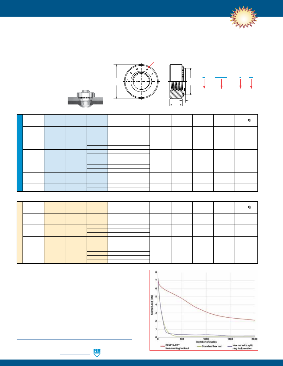
LN-10
PennEngineering •
www.pemnet.com
SELF-LOCKING FASTENERS
U
NIF
IE
D
A
Rec.
Hole Size
Min. Dist
Thread
Type
Thread
Shank
(Shank)
Min. Sheet
In Sheet
C
E
T
Hole
CL
Size
Code
Code
Max.
Thickness (1)
+.003 –.000
Max.
±.010
±.010
To Edge
.112-40 0 .030 .030
(#4-40)
S RT440 1 .038 .040 .166 .165 .250 .070 .19
2
.054
.056
.138-32 0 .030 .030
(#6-32)
S RT632 1 .038 .040 .1875 .187 .280 .070 .22
2
.054
.056
.164-32 0 .030 .030
(#8-32)
S RT832 1 .038 .040 .213 .212 .310 .090 .27
2
.054
.056
.190-32 0 .030 .030
(#10-32)
SS RT032 1 .038 .040 .250 .249 .340 .090 .28
2
.054
.056
.250-20 0 .045 .047
(1/4-20)
S RT0420 1 .054 .056 .344 .343 .440 .170 .34
2
.087
.090
.313-18
S RT0518 1 .054 .056 .413 .412 .500 .230 .38
(5/16-18)
2 .087 .090
All dimensions are in inches.
ME
TR
IC
Thread
A
Rec.
Hole Size
Min. Dist
Size x
Type
Thread
Shank
(Shank)
Min. Sheet
In Sheet
C
E
T
Hole
CL
Pitch
Code
Code
Max.
Thickness (1)
+0.08
Max.
±0.25
±0.25
To Edge
0
0.77
0.8
M3 x 0.5
S RTM3 1 0.97 1 4.22 4.2 6.35 1.5 4.8
2
1.38
1.4
0
0.77
0.8
M4 x 0.7
S
RTM4
1
0.97
1
5.41
5.38
7.87
2
6.9
2
1.38
1.4
0
0.77
0.8
M5 x 0.8
SS
RTM5
1
0.97
1
6.35
6.33
8.64
2
7.1
2
1.38
1.4
00
0.89
0.92
M6 x 1
S
RTM6 0 1.15 1.2 8.75 8.73 11.18 4.08 8.6
1
1.38
1.4
2
2.21
2.29
All dimensions are in millimeters
NEW!
E
C
T
A
Clinching profile may vary.
“PEM RT” Stamp (Trademark)
Type
Finish
PART NUMBER DESIGNATION
Thread
Size Code
Shank
Code
S - RT632 – 1
ZI
The graph represents the clamp load of the joint versus the amount of
cycles during transverse vibration testing for an S-RT™ free-running
locknut, a standard hex nut and a hex nut with a split ring lock washer.
Testing conditions:
Transverse vibration testing.
M6 thread size nuts, average of 30 pieces.
Clamp load applied using metric property class 10.9 screws.
Nuts tested until loss of clamp load or 2,000 cycles is reached.
S-RT™ FREE-RUNNING LOCKNUTS
Free-running locking feature allows screw to turn freely until clamp load is applied. If the tightening force is removed, these nuts no
longer provide any torsional resistance to rotation.
•
Resistant to vibrational loosening.
•
Back side of panel is flush or sub-flush for screw
installation.
•
Locking feature reusability is not affected by
number of on/off cycles.
•
Uses same mounting hole and installation
tooling as standard S™ nuts.
•
Recommended for use in steel or aluminum sheets
HRB 80 / HB 150 or less.
Details on PEM® RT™ vibration resistant thread technology
can be found on our web site at:
https://www.pemnet.com/files/design_info/techsheets/RT_Thread_Form.pdf
pem-html.html
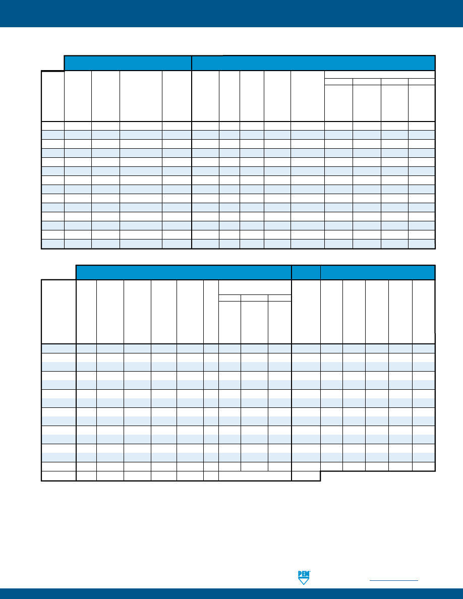
SELF-LOCKING FASTENERS
PennEngineering •
www.pemnet.com
LN-11
MATERIAL AND FINISH SPECIFICATIONS
Nylon Locking
Internal,
Element Retainer Retainer Retainer Nut
Internal,
Internal,
UNJ Class 3B per
(1)
Blue or Black
Type
ASME
ASME
ASME B1.15 /
Modified
300
Temperature
Hardened
300
300
B1.1, 2B /
B1.1, 3B /
MJ Class 4H6H per Thread Form Hardened
Series
(2)
Limit
Hardened
400 Series
Series
Series
ASME
ASME
ASME B1.21M
on Loaded
Carbon
Carbon Stainless
7075-T6
250˚ F/
Carbon
Stainless
Stainless
Stainless
B1.13M, 6H
B1.13M, 6H
(M6 thread 4H5H)
Flank
Steel
Steel
Steel
Aluminum
120˚ C
Steel
Steel
Steel
Steel
CFN
•
•
•
FE
•
•
FEO
•
•
UL
•
•
LAS
•
• •
LAC
•
• •
LA4
•
• •
LK
•
•
LKS
•
•
LKA
•
•
PL
•
• •
PLC
•
•
•
SL
•
•
S-RT
• •
Floating Fastener
(1) Will accept a maximum material 6g/2A screw.
(2) Mating screws must be lubricated.
(3) See PEM Technical Support section of our web site for related plating standards and specifications.
(4) Special order with additional charge.
(5) HRB - Hardness Rockwell “B” Scale. HB - Hardness Brinell.
(6) MD finish on stainless steel provides a minimum of 100 hours of salt spray resistance.
(7) MD finish on steel provides a minimum of 24 hours of salt spray resistance.
Retainer Retainer Nut
(7)
Type
Zinc Passivated Passivated
Black
Zinc Passivated
Plated, and/or Plus
(6) Dry-film Plated, and/or
Zinc
5µm,
Tested Per
Clear
Black
Lubricant
5µm,
Tested Per
Black
Plated
HRB 88/ HRB 80/
HRB 70/
HRB 60/ HRB 50/
Color- ASTM Dry-film Dry-film Over Color- ASTM Dry-film 5µm,
HB 183
HB 150
HB 125
HB 107
HB 89
less
A380
Lubricant
Lubricant Phosphate Plain
less
A380
Lubricant
Yellow
or Less
or Less
or Less
or Less
or Less
CFN
•
• •
FE
•
•
FEO
•
•
UL
•
•
LAS
• • •
LAC
• • •
LA4
• • •
LK
•
•
LKS
•
•
LKA
•
•
PL
•
• •
PLC
•
•
SL
•
•
S-RT
•
•
•
Finish Codes
ZI
None CW MD MD
MD ZC
Floating Fastener
Standard Finishes (3)
Optional
For Use In Sheet Hardness: (5)
Finish (3)(4)
Threads
Fastener Material
pem-html.html
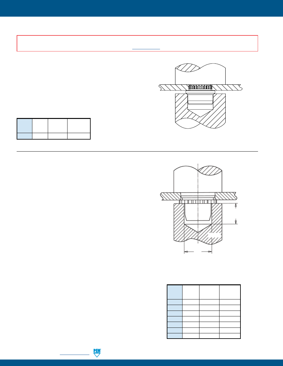
LN-12
PennEngineering •
www.pemnet.com
SELF-LOCKING FASTENERS
CFN™ NUTS
1.
Prepare properly sized mounting hole in sheet. Do not perform any
secondary operations such as deburring.
2.
Insert fastener into the anvil hole and place the mounting hole over
the shank of the fastener (preferably the punch side) as shown in
drawing.
3.
With installation punch and anvil surfaces parallel, apply squeezing
force until the shoulder of the fastener contacts the sheet.
INSTALLATION
FE™/FEO™/UL™ NUTS
1.
Prepare properly sized mounting hole in sheet. Do not perform any
secondary operations such as deburring.
2.
Insert fastener into the anvil hole and place the mounting hole
(preferably the punch side) over the shank of the fastener as shown in
the drawing.
3.
With installation punch and anvil surfaces parallel, apply squeezing
force to the knurled collar until knurled collar is flush with top of the
sheet for sheets .060”/1.5 mm thick and up, or until shank is flush with
the bottom of the sheet for sheets .040” / 1 mm to .060”/1.5 mm thick
for FE/FEO nuts.
PEM miniature fasteners must be installed by a force applied through parallel
surfaces. Since force must not be applied to the barrel, a cavity must be used in
either the punch or anvil so that the installation force is applied to the knurled collar.
“D” dimensions for the punch or anvil cavity are given in the tables on page 5.
INSTALLATION RECOMMENDATION
In applications for sheet thicknesses between the two ranges (see “Sheet
Thickness” on page 5) use the fastener with the larger “A” dimension. For
example, if you want a #4-40 thread and your sheet thickness is between
.045”/1.14 mm and .059”/1.49 mm, you should use FE or FEX nuts. This is not
recommended installation practice, but in this case if it is necessary, you should
install the fastener so that the bottom of the shank is flush with the underside
of the sheet (instead of having the top of the knurled collar flush with the top of
the sheet). When this method is used, care must be taken to protect the fastener
against crushing which would damage the threads. This method will also result in
reduced pushout and torque-out values.
PEMSERTER® Installation Tooling
Anvil
Punch
Type Thread
Part Part
Code
Number Number
CFN 440/M3 8012038 975200048
PEMSERTER® Installation Tooling
Anvil
Punch
Type Thread
Part Part
Code
Number Number
UL 256/M2 975200020 975200048
FE/FEO 440/M3 975200021 975200048
FE/FEO 632/M3.5 975200022 975200048
FE/FEO 832/M4 975200023 975200048
FE/FEO 032/M5 975200024 975200048
FE/FEO
0420
975200025 975200048
FE/FEO
M6
8013143
975200048
PUNCH
T Max.
+.010” / +0.25 mm
Min.
D
+.005” / +0.13 mm
+.010” / +0.25 mm
ANVIL
For “D” see page 5
For “T” see page 5
PUNCH
ANVIL
SHEET
INSTALLATION NOTES
•
For best results we recommend using a PEMSERTER® press for installation of PEM self-clinching fasteners. Please check our website for more information.
•
Visit the Animation Library on our website to view the installation process
for select products
.
pem-html.html
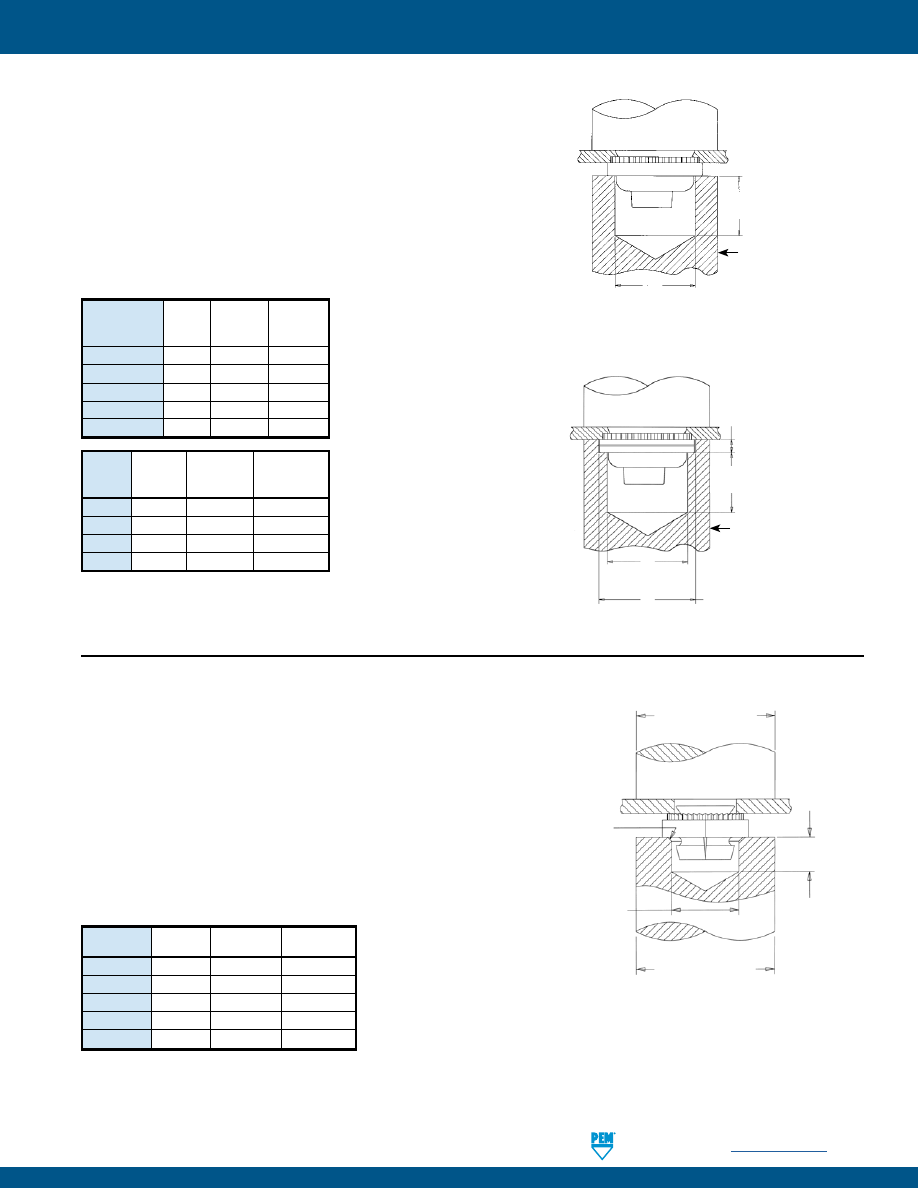
SELF-LOCKING FASTENERS
PennEngineering •
www.pemnet.com
LN-13
LAS™/LAC™/LA4™ NUTS
1.
Prepare properly sized mounting hole in sheet. Do not perform any
secondary operations such as deburring.
2.
Place fastener into the anvil hole and place the mounting hole
(preferably the punch side) over the shank of the fastener.
3.
With installation punch and anvil surfaces parallel, apply sufficient
squeezing force until flange contacts mounting sheet (LAC/LAS)
or until anvil contacts the mounting sheet (LA4). Drawings show
suggested tooling for applying these forces.
PEMSERTER® Installation Tooling
PUNCH
.25” / 8 mm
Min.
D
+.005” / +0.13 mm
+.010” / +0.25 mm
ANVIL
LAC/LAS
For “D” see page 6
Anvil
Punch
Type Thread
Part Part
Code
Number Number
LA4 440/M3 8013889
975200048
LA4
632
8013890
975200048
LA4 832/M4 8013891
975200048
LA4 032/M5 8013892
975200048
Anvil Punch
Type Thread
Part Part
Code
Number Number
LAC/LAS
440/M3 975200006 975200048
LAC/LAS
632 8013890 975200048
LAC/LAS 832/M4 8013891 975200048
LAC/LAS 032/M5 8013892 975200048
LAC/LAS
0420/M6 975200010 975200048
LK™/LKS™/LKA™ NUTS
1.
Prepare properly sized mounting hole in sheet. Do not perform any
secondary operations such as deburring.
2.
Insert fastener into the anvil hole and place the mounting hole over
the shank of fastener (preferably the punch side) as shown in drawing.
3.
With installation punch and anvil surfaces parallel, apply squeezing
force until hexagonal shoulder contacts mounting sheet. Sketch at the
right shows suggested tooling for applying these forces. Installation
force and performance data shown below.
PEMSERTER® Installation Tooling
Type Thread Anvil Punch
Code
Part Number
Part Number
LK/LKS/LKA 256/M2.5
975200015
975200048
LK/LKS/LKA 440/M3
975200016
975200048
LK/LKS/LKA
632
975201242
975200048
LK/LKS/LKA 832/M4
975201241
975200048
LK/LKS/LKA 032/M5
975200019
975200048
.500” / 13 mm
Dia. Min.
.218” / 5.5 mm
Min.
D
+.005” / +0.13 mm
+.010” / +0.25 mm
.500” / 13 mm
Dia. Min.
PUNCH
Break
Corner
.005” /
0.13 mm
Max.
ANVIL
For “D” see page 7
LA4
Tooling for installation into stainless steel sheets
PUNCH
D
+.002”/+0.05 mm
+.005”/+0.13 mm
E
+.004” / +0.1 mm
–.000”
.054” / 1.37 mm
±.002” / ±0.05 mm
ANVIL
.25”/8 mm
Min.
For “D” and “E” see page 6
pem-html.html
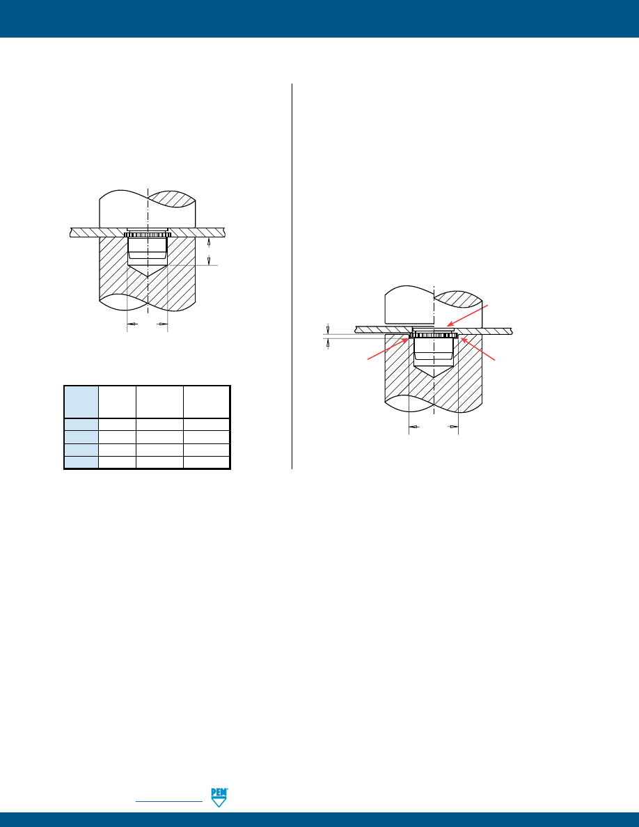
LN-14
PennEngineering •
www.pemnet.com
SELF-LOCKING FASTENERS
PL™/PLC™ NUTS
Sheet thickness .060” to .070” / 1.53 mm to 1.78 mm
1.
Prepare properly sized mounting hole in sheet. Do not
perform any secondary operations such as deburring.
2.
Insert fastener into the anvil hole and place the mounting
hole over the shank of the fastener (preferably the punch
side) as shown in drawing.
3.
With the punch and anvil surfaces parallel, apply a
squeezing force until the knurled collar is flush with the
top sheet.
Sheet thickness .040” to .060” / 1 mm to 1.53 mm
1.
Prepare properly sized mounting hole in sheet. Do not
perform any secondary operations such as deburring.
2.
Insert fastener into the anvil hole and place the mounting
hole over the shank of the fastener (preferably the punch
side) as shown in drawing.
3.
With the punch and anvil surfaces parallel, apply a squeezing
force until the fastener shank is flush with the underside of
the sheet. This should be accomplished by setting the depth
of the counterbore in the anvil to the difference between the
“A” dimension and the sheet thickness
*
. When this method
is used, care must be taken to protect the fastener against
crushing which would damage the threads. This method will
also result in reduced pushout and torque-out values.
PEMSERTER® Installation Tooling
Anvil
Punch
Type Thread
Part Part
Code
Number Number
PL/PLC 440/M3
975200011 975200048
PL/PLC
632
975200012 975200048
PL/PLC 832/M4 975200013 975200048
PL/PLC 032/M5 975200014 975200048
+.005” / +0.13 mm
+.010” / +0.25 mm
PUNCH
ANVIL
SHEET
.187” / 5 mm
Min.
For “D” see page 8
D
PUNCH
ANVIL
SHEET
Bottom of fastener
shank smooth with
sheet.
BEFORE AFTER
+.005” / +0.13 mm
+.010” / +0.25 mm
*
Knurled collar
sits in anvil
counterbore.
Knurled collar must
be left protruding
above sheet.
For “E” see page 8
E
pem-html.html
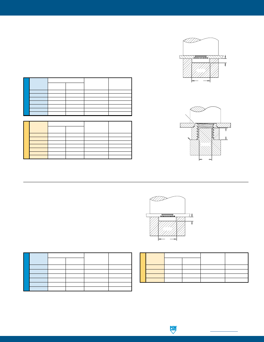
SELF-LOCKING FASTENERS
PennEngineering •
www.pemnet.com
LN-15
ME
TR
IC
U
NIF
IE
D
SL™ NUTS
1.
Prepare properly sized mounting hole in sheet. Do not perform any
secondary operations such as deburring.
2.
Insert fastener into the anvil hole and place the mounting hole over the shank
of the fastener (preferably the punch side) as shown in drawing.
3.
With installation punch and anvil surfaces parallel, apply squeezing force until
the head of the nut comes into contact with the sheet material.
Anvil Dimensions (in.)
Thread
A P
Anvil Part
Punch Part
Code
±.002 ±.005 Number Number
440
.267
.045
975200034
975200048
632
.298
.045
975200035
975200048
832
.330
.070
975200036
975200048
032
.361
.070
975200037
975200048
0420
.454
.150
975200038
975200048
0518
.515
.200
975200039
975200048
0616
.280
.250
975200045
(1)
975200048
Anvil Dimensions (mm)
Thread
A P
Anvil Part
Punch Part
Code
±0.05 ±0.13 Number Number
M3
6.78
1.14
975200034
975200048
M3.5
7.57
1.14
975200035
975200048
M4
8.38
1.78
975200036
975200048
M5
9.17
1.78
975200037
975200048
M6
11.53
3.81
975200038
975200048
M8
13.08
5.08
975200039
975200048
M10
7.62
6.35
8005682
(1)
975200901400
PEMSERTER® Installation Tooling
(1) Large nut anvils use protrusion to locate part instead of counterbore.
PUNCH
ANVIL
A
P
COUNTERBORE ANVIL
Thread Sizes #2-56 to 5/16
and M2 to M8
PROTRUSION ANVIL
CLS/S Nuts Thread Sizes 3/8,1/2, M10 and M12
45˚ x .010”/
0.254 mm
R .015” /
0.381 mm
A
P
PUNCH
ANVIL
S-RT™ NUTS
1.
Prepare properly sized mounting hole in sheet. Do not
perform any secondary operations such as deburring.
2.
Place fastener into the anvil hole and place the
mounting hole (preferably the punch side) over the
shank of the fastener as shown in diagram to the right.
3.
With installation punch and anvil surfaces parallel,
apply squeezing force until the head of the nut comes
into contact with the sheet material.
PEMSERTER® Installation Tooling
PUNCH
ANVIL
A
P
ME
TR
IC
U
NIF
IE
D
Anvil Dimensions (in.)
Thread
A P
Anvil Part
Punch Part
Code
±.002
±.005
Number
Number
RT440
.267
.045
975200034
975200048
RT632
.298
.045
975200035
975200048
RT832
.330
.070
975200036
975200048
RT032
.361
.070
975200037
975200048
RT0420
.454
.150
975200038
975200048
RT0518
.517
.200
975200039
975200048
Anvil Dimensions (mm)
Thread
A P
Anvil Part
Punch Part
Code
±0.05
±0.13
Number
Number
RTM3
6.78
1.14
975200034
975200048
RTM4
8.38
1.78
975200036
975200048
RTM5
9.17
1.78
975200037
975200048
RTM6 11.53 3.81 975200038
975200048
pem-html.html
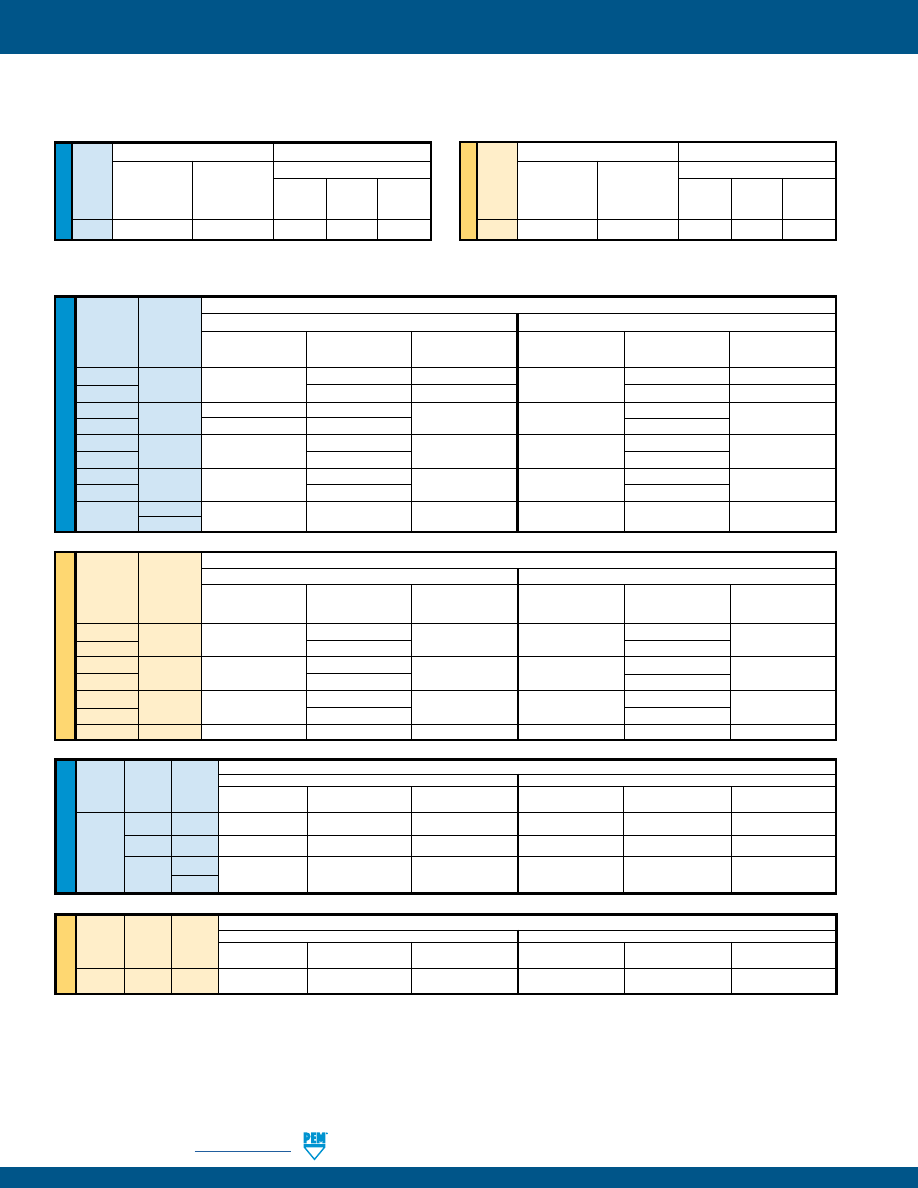
LN-16
PennEngineering •
www.pemnet.com
SELF-LOCKING FASTENERS
FE™/FEO™/UL™ NUTS
(1)(2)
(1) Published installation forces are for general reference. Actual set-up and confirmation of complete installation should be made by observing
proper seating of fastener as described in the installation steps. Other performance values reported are averages when all proper
installation parameters and procedures are followed. Variations in mounting hole size, sheet material, and installation procedure may affect
performance. Performance testing this product in your application is recommended. We will be happy to provide technical assistance and/
or samples for this purpose.
(2) For FE and FEO fasteners, thread locking performance is equivalent to applicable NASM25027 specifications. For details, see chart on page 21.
ME
TR
IC
U
NIF
IE
D
Test Sheet Material
5052-H34 Aluminum
Cold-rolled Steel
Type Thread Shank
Installation
Pushout Torque-out Installation Pushout Torque-out
Code Code
(lbs.)
(lbs.)
(in. lbs.)
(lbs.)
(lbs.)
(in. lbs.)
080 0
750
20
2
1000
30
2
UL
164
0
750
20
3
1000
30
3
256
0
1000 20
4
1300 30
4
1
Test Sheet Material
5052-H34 Aluminum
Cold-rolled Steel
Type Thread
Shank
Installation Pushout Torque-out Installation Pushout Torque-out
Code Code (kN)
(N)
(N•m)
(kN)
(N)
(N•m)
UL M2 1
4
89
0.45
5.8
133
0.45
ME
TR
IC
U
NIF
IE
D
Test Sheet Material
5052-H34 Aluminum
Cold-rolled Steel
Thread
Type
Code
Installation Pushout Torque-out Installation Pushout Torque-out
(lbs.)
(lbs.)
(in. lbs.)
(lbs.)
(lbs.)
(in. lbs.)
FEO
440
900
88 12
1500
140 12
FE
135
12
210
12
FEO
632
1200
105
20 2100
185
20
FE
1300
175
255
FEO
832
1500
155
48 2500
260
48
FE
255
360
FEO
032
1500
155
48 2500
260
48
FE
255
360
FE
0420
2100
320
110
3500
420
110
0428
Test Sheet Material
5052-H34 Aluminum
Cold-rolled Steel
Thread
Type
Code
Installation
Pushout
Torque-out
Installation
Pushout
Torque-out
(kN)
(N)
(N•m)
(kN)
(N)
(N•m)
FEO
M3
4
391
1.35
6.7
622
1.35
FE
600
934
FEO
M4
6.7
689
5.42 11.1
1156
5.42
FE
1134
1601
FEO
M5
6.7
689
5.42 11.1
1156
5.42
FE
1134
1601
FE
M6
9.4
1423
12.43
15.6
1868
12.43
CFN™ NUTS
(1)
CLINCH FASTENER PERFORMANCE DATA
ME
TR
IC
U
NIF
IE
D
Thread Locking Specifications
Test Sheet Material
Max.
Min.
.040” Cold-rolled Steel
Thread
First On
First Off
Code
Prevailing Torque
Prevailing Torque Installation Pushout Torque-out
(in. lbs.)
(in. lbs.)
(lbs.)
(lbs.)
(in. lbs.)
440
3
0.38
1000
10
4
Thread Locking Specifications
Test Sheet Material
Max.
Min.
1 mm Cold-rolled Steel
Thread
First On
First Off
Code
Prevailing Torque
Prevailing Torque Installation Pushout Torque-out
(N•m)
(N•m)
(kN) (N) (N•m)
M3
0.339
0.042
4.45
44.5
0.45
pem-html.html
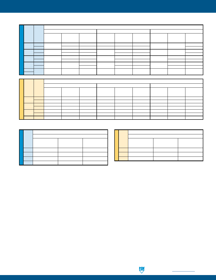
SELF-LOCKING FASTENERS
PennEngineering •
www.pemnet.com
LN-17
ME
TR
IC
U
NIF
IE
D
(1) Published installation forces are for general reference. Actual set-up and confirmation of complete installation should be made by observing
proper seating of fastener as described in the installation steps. Other performance values reported are averages when all proper
installation parameters and procedures are followed. Variations in mounting hole size, sheet material, and installation procedure may affect
performance. Performance testing this product in your application is recommended. We will be happy to provide technical assistance and/
or samples for this purpose.
(2) Thread locking performance is equivalent to applicable NASM25027 specifications. For details, see chart on page 21.
Test Sheet Material
300 Series Stainless Steel
Thread
Retainer Retainer
Code
Installation
Pushout Torque-out
(lbs.)
(lbs.)
(in. lbs.)
440
9000
200
85
632
10000
200
85
832
12000
200
85
032
13000
250
125
Test Sheet Material
300 Series Stainless Steel
Thread
Retainer Retainer
Code
Installation
Pushout Torque-out
(kN)
(N) (N•m)
M3
40
890
9.6
M4
53
890
9.6
M5
57
1100
14.1
LAS™/LAC™ NUTS
(1)(2)
LA4™ NUTS
(1)(2)
ME
TR
IC
U
NIF
IE
D
Test Sheet Material
2024-T3 Aluminum
5052-H34 Aluminum
Cold-Rolled Steel
Thread Shank
Retainer Retainer
Retainer Retainer
Retainer Retainer
Code Code
Installation
Pushout Torque-out Installation
Pushout Torque-out Installation
Pushout Torque-out
(lbs.)
(lbs.)
(in. lbs.)
(lbs.)
(lbs.)
(in. lbs.)
(lbs.)
(lbs.)
(in. lbs.)
440 1 3000 220 65 1500 215 65 3000 300 85
2
225
150
2000
225
80
150
632 1 3000 235 110 2000 240 140 3000 300 150
2
275
150 250
150 175
832 1 3000 240 110 2000 250 140 3000 300 150
2
300
150 265
150 400
200
032 1 3500 300 150 2000 300 150 3500 400 150
2
200
350
175
450
200
0420
2
5000 300 325 3000 400 325 5000 500 325
0428
Test Sheet Material
2024-T3 Aluminum
5052-H34 Aluminum
Cold-Rolled Steel
Thread Shank Retainer Retainer Retainer Retainer Retainer Retainer
Code Code
Installation
Pushout Torque-out Installation
Pushout Torque-out Installation
Pushout Torque-out
(kN)
(N) (N•m) (kN)
(N) (N•m) (kN)
(N) (N•m)
M3
1 13.3 978 7.3 6.7 956 7.3 13.3 1334 9.6
2
13.3
1000
16.9
8.9
1000
9
13.3
1334
16.9
M4
1 13.3 1067 12.4 8.9
1112 15.8 13.3 1334 16.9
2
15.6
1334
16.9
8.9
1178
16.9
13.3
1779
22.6
M5
1
15.6 1334 16.9 8.9 1334 16.9 15.6 1779 16.9
2
16.6
1334
22.6
8.9
1556
19.7
15.6
2001
22.6
M6
2
22.2
1334
36.7
13.3
1779
36.7
22.2
2224
36.7
pem-html.html
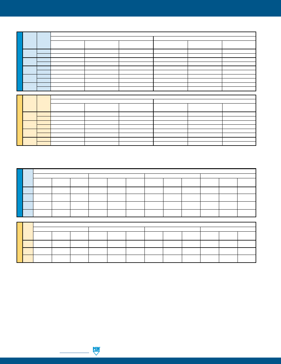
LN-18
PennEngineering •
www.pemnet.com
SELF-LOCKING FASTENERS
U
NIF
IE
D
Test Sheet Material
5052-H34 Aluminum
Cold-rolled Steel
Thread Shank
Code
Code
Installation Pushout Torque-out Installation Pushout Torque-out
(lbs.)
(lbs.)
(in. lbs.)
(lbs.)
(lbs.)
(in. lbs.)
256 1 1600
130
20
3000
150
20
2
2000
150
30
3000
160
20
440 1
1600
130
25
3000
150
30
2
2000
200
35
3000
250
40
632 1
2400
130
25
4000
150
45
2
2700
225
45
4300
275
50
832 1
2700
150
45
4000
190
50
2
3000
250
50
4300
300
70
032 1
3200
150
90
4000
250
100
2
3200
250
105
4300
300
120
ME
TR
IC
Test Sheet Material
5052-H34 Aluminum
Cold-rolled Steel
Thread Shank
Code
Code
Installation Pushout Torque-out Installation Pushout Torque-out
(kN)
(N)
(N•m)
(kN)
(N)
(N•m)
M2.5 1 7.1
578
2.3
13.3
667
2.3
2
8.9
667
3.4
13.3
711
2.3
M3 1
7.1
578
2.8
13.3
667
3.4
2
8.9
890
4
13.3
1112
4.5
M4 1
12
667
5.1
17.8
845
5.6
2
13.3
1112
5.7
19.1
1334
7.9
M5 1
14.2
667
10.2
17.8
1112
11.3
2
14.2
1112
11.9
19.1
1334
13.6
LK™/LKS™/LKA™ NUTS
(1)(2)
ME
TR
IC
U
NIF
IE
D
Test Sheet Material
Thread
.060” 5052-H34 Aluminum
.040” 5052-H34 Aluminum
.060” Cold-rolled Steel
.048” Cold-rolled Steel
Code Installation Pushout Torque-out Installation Pushout Torque-out Installation Pushout Torque-out Installation Pushout Torque-out
(lbs.)
(lbs.)
(in. lbs.)
(lbs.)
(lbs.)
(in. lbs.)
(lbs.)
(lbs.)
(in. lbs.)
(lbs.)
(lbs.)
(in. lbs.)
440
2000 225 20 1500 160 20 3000 260 20 3000 225 20
632
2000
285
30
1500
180
25
3000
290
30
3000
270
30
832
2000
290
60
1500
180
28
3000
290
60
3000
270
60
032
2000
300
70
1500
180
40
3000
350
70
3000
310
70
Test Sheet Material
Thread
1.5 mm 5052-H34 Aluminum
1 mm 5052-H34 Aluminum
1.5 mm Cold-rolled Steel
1.2 mm Cold-rolled Steel
Code Installation Pushout Torque-out Installation Pushout Torque-out Installation Pushout Torque-out Installation Pushout Torque-out
(kN)
(N)
(N • m)
(kN)
(N)
(N • m)
(kN)
(N)
(N • m)
(kN)
(N)
(N • m)
M3
8.9 1000 2.25 6.67 710 2.25 13.34 1156 2.25 13.34 1000 2.25
M4
8.9
1290
6.77
6.67
800
3.16
13.34
1290
6.77
13.34
1200
6.77
M5
8.9
1330
7.9
6.67
800
4.51
13.34
1557
7.9
13.34
1380
7.9
PL™/PLC™ NUTS
(1)(2)
(1) Published installation forces are for general reference. Actual set-up and confirmation of complete installation should be made by observing
proper seating of fastener as described in the installation steps. Other performance values reported are averages when all proper
installation parameters and procedures are followed. Variations in mounting hole size, sheet material, and installation procedure may affect
performance. Performance testing this product in your application is recommended. We will be happy to provide technical assistance and/
or samples for this purpose.
(2) Thread locking performance is equivalent to applicable NASM25027 specifications. For details, see chart on page 21.
pem-html.html
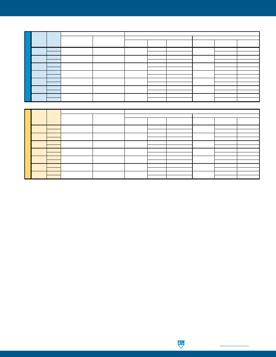
SELF-LOCKING FASTENERS
PennEngineering •
www.pemnet.com
LN-19
SL™ NUTS
(1)
(1) Published installation forces are for general reference. Actual set-up and confirmation of complete installation should be made by observing
proper seating of fastener as described in the installation steps. Other performance values reported are averages when all proper installation
parameters and procedures are followed. Variations in mounting hole size, sheet material, and installation procedure may affect performance.
Performance testing this product in your application is recommended. We will be happy to provide technical assistance and/or samples for
this purpose.
U
NIF
IE
D
Thread Locking Specifications
Test Sheet Material
Thread Shank Max. Prevailing Torque
Min. Prevailing Torque
5052-H34 Aluminum
Cold-rolled Steel
Code
Code
(1st thru 3rd)
(1st thru 3rd)
Installation
Pushout Torque-out Installation Pushout Torque-out
(in. lbs.)
(in. lbs.)
(lbs.)
(lbs.)
(in. lbs.)
(lbs.)
(lbs.)
(in. lbs.)
440
1
5.75
0.4
1500 - 2000
90 10
2500 - 3500
125 15
2
170
13
230
18
632 1
10.5
0.8
2500 - 3000 95
17
3000 - 6000 130
20
2
190
22
275
28
832 1
18
1.2
2500 - 3000 105
23
4000 - 6000 145
35
2
220
35
285
45
032 1
21
1.65
2500 - 3000 110
32
4000 - 9000 180
40
2
190
50
250
60
0420 1
35 3.75
4000 - 7000 360
90
6000 - 9000 400
150
2
360
125
400
150
0518 1
53
4.75
4000 - 7000 380
120
6000 - 8000 420
165
2
380 160
420 180
0616 1
95
6.3
5000 - 8000 400
270
7000 - 11000 460
320
2
400 270
460 320
ME
TR
IC
Thread Locking Specifications
Test Sheet Material
Thread
Shank
Max. Prevailing Torque
Min. Prevailing Torque
5052-H34 Aluminum
Cold-rolled Steel
Code
Code
(1st thru 3rd)
(1st thru 3rd)
Installation Pushout Torque-out Installation Pushout Torque-out
(N•m)
(N•m)
(kN) (N) (N•m) (kN) (N) (N•m)
M3
1
0.67
0.04
6.7 - 8.9
400 1.13
11.2 - 15.6
550 1.7
2
750
1.47
1010
2.03
M3.5 1
1.2
0.08
11.2 - 13.5 400
1.92 13.4 - 26.7 570 2.3
2
840
2.5
1210
2.3
M4 1
2.1
0.13
11.2 - 13.4 470
2.6
18 - 27 645 4
2
970
4
1250
5.1
M5 1
2.4
0.18
11.2 - 15.6 480
3.6
18 - 38 800 4.5
2
845
5.7
1112
6.8
M6 1
4
0.3
18 - 32 1580 10.2 27 - 36 1760 17
2
1580
14.1
1760
17
M8 1
6
0.5
18 - 32 1570 13.6 27 - 36 1870 18.7
2
1570
18.1
1870
20.3
M10 1
12
0.8
22 - 36 1760 32.7 32 - 50 2020 36.2
2
1760
32.7
2020
36.2
pem-html.html
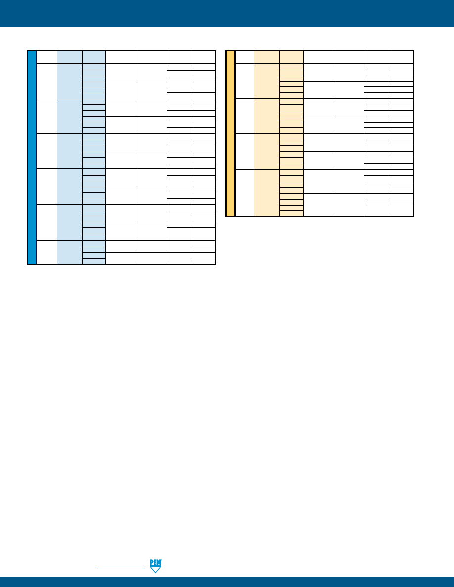
LN-20
PennEngineering •
www.pemnet.com
SELF-LOCKING FASTENERS
S-RT™ NUTS
(1)
U
NIF
IE
D
Type
Thread
Shank
Test Sheet
Installation
Pushout
Torque-out
Code
Code
Material
(lbs.)
(lbs.)
(in. lbs.)
0
5052-H34
63 8
1
Aluminum 1500-2000 90
10
S RT440 2
170 13
0
Cold-rolled 105 13
1
Steel 2500-3500 125 15
2
230
18
0
5052-H34
63 16
1
Aluminum 2500-3000 95
17
S RT632 2
190 22
0
Cold-rolled 110 16
1
Steel 3000-6000 130 20
2
275
28
0
5052-H34 68 21
1
Aluminum 2500-3000 105
23
S RT832 2
220 35
0
Cold-rolled
110 26
1
Steel 4000-6000 145 35
2
285
45
0
5052-H34
68 26
1
Aluminum 2500-3500 110
32
SS RT032 2
190 50
0
Cold-rolled
120 32
1
Steel 4000-9000 180 40
2
320
60
0
5052-H34 220 70
1
Aluminum 4000-7000 360 90
S RT0420 2
125
0
Cold-rolled
315 115
1
Steel 6000-8000 400 150
2
1
5052-H34 4000-7000 380 120
S RT0518 2 Aluminum
160
1
Cold-rolled 6000-8000 420 165
2
Steel
180
ME
TR
IC
Type
Thread
Shank
Test Sheet
Installation
Pushout
Torque-out
Code
Code
Material
(kN)
(N)
(N•m)
0
5052-H34
280 0.9
1
Aluminum 6.7-8.9 400 1.13
S RTM3 2
750 1.47
0
Cold-rolled
470 1.47
1
Steel 11.2-15.6 550 1.7
2
1010
2.03
0
5052-H34
300 2.37
1
Aluminum 11.2-13.4 470 2.6
S RTM4 2
970 4
0
Cold-rolled
490 2.95
1
Steel 18-27 645 4
2
1250 5.1
0
5052-H34 300 3
1
Aluminum 11.2-15.6 480 3.6
SS RTM5 2
845 5.7
0
Cold-rolled
530 3.6
1
Steel 18-38 800 4.5
2
1112
6.8
00
750
6.5
0
5052-H34
18-32 970 7.9
1
Aluminum
1580 10.2
S RTM6 2
14.1
00
900
10
0
Cold-rolled
27-36 1380 13
1
Steel
1760 17
2
(1) Published installation forces are for general reference. Actual set-up and confirmation of complete installation should be made by observing
proper seating of fastener as described in the installation steps. Other performance values reported are averages when all proper installation
parameters and procedures are followed. Variations in mounting hole size, sheet material, and installation procedure may affect performance.
Performance testing this product in your application is recommended. We will be happy to provide technical assistance and/or samples for
this purpose.
pem-html.html
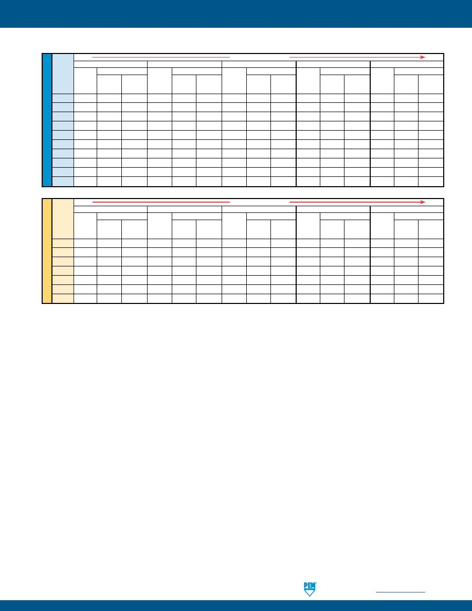
SELF-LOCKING FASTENERS
PennEngineering •
www.pemnet.com
LN-21
AXIAL STRENGTH AND TIGHTENING TORQUE COMPARISON
U
NIF
IE
D
Types UL-0/FEO
Types UL-1/FE
Types PL/PLC
Type SL
Types LK/LKA/LKS/LAC/LAS/LA4
Thread Locknut Mating Screw
Locknut Mating Screw
Locknut Mating Screw
Locknut Mating Screw
Locknut Mating Screw
Code Min. Axial Strength Tightening Min. Axial Strength Tightening Min. Axial Strength Tightening Min. Axial Strength Tightening Min. Axial Strength Tightening
Strength Level Torque Strength Level Torque Strength Level Torque Strength Level Torque Strength Level Torque
(lbs.)
(1)
(ksi)
(2)
(in. lbs.)
(3)
(lbs.)
(1)
(ksi)
(2)
(in. lbs.)
(3)
(lbs.)
(1)
(ksi)
(2)
(in. lbs.)
(3)
(lbs.)
(4)
(ksi)
(4)
(in. lbs.)
(5)
(lbs.)
(7)
(ksi)
(7)
(in. lbs.)
(5)
080
125 69 1.0 — — — — — — — — — — — —
164
125 49 1.2 — — — — — — — — — — — —
256
169 46 1.9 316 85 3.5 — — — — — — — — —
440 465 77 6.8 705 117 10.3 897 149 13.1 1,085 180 15.8 1,085 180 15.8
632 546 60 9.8 847 93 15.2 1,036 114 18.6 1,636 180 29.4 1,636 180 29.4
832
779
56
16.6
1,213
87
25.9
1,179
84
25.1
2,270
(6)
180 48.4 2,522 180 53.8
032
779
39
19.2
1,213
61
30.0
1,246
62
30.8 2,880
(6)
180 71.1 3,600 180 88.9
0420
— — — 1,412 44 45.9 — — — 5,728
180 186
5,728
180 186
0518
— — — — — — — — — 9,437
180 383 — — —
0616
— — — — — — — — —
13,948
180 680 — — —
(1) Axial strength for UL, FEO, FE, PL and PLC locknuts are limited by knurled ring strength.
(2) Screw strength level shown is the minimum needed to develop full nut strength, higher strength screws may be used.
(3) Tightening torque shown will induce preload of 65% of locknut min axial strength with K or nut factor is equal to 0.20. In some applications tightening
torque may need to be adjusted based on the actual K value. If heat treated steel screw strength is less than the value shown, tightening torque
should be proportionately reduced by multiplying the torque shown by the actual screw strength over the screw strength shown. For screws of other
materials, never exceed the lower of this reduced torque or the tightening torque recommended for the screw. If higher strength screws are used,
torque is not adjusted upward because assemble strength is still limited by locknut strength.
(4) Unless otherwise noted, (see note 6) SL locknuts have axial strength exceeding the min tensile strength of 180 ksi/Property Class 12.9 screws. Contact
tech support regarding assemble strength for higher strength screws.
(5) Tightening torque shown will induce preload of 65% of locknut min axial strength with K or nut factor is equal to 0.20. In some applications tightening
torque may need to be adjusted based on the actual K value. All tightening torques shown are based on 180 ksi/ Property Class 12.9 screws. For
lower strength heat treated steel screws the tightening torque is proportionately less. For example, for 120 ksi screws (Grade 5), torque is 67% of value
shown. For 900 MPa screws (Property Class 9.8) torque value is 74% of value shown. For screws of other materials, never exceed the lower of this
reduced torque or the tightening torque recommended for the screw.
(6) Due to limited nut height in this size, failure mode is screw stripping and axial strength value shown is slightly less than min tensile strength of 180 ksi/
Property class 12.9 screw.
(7) All LK, LKS, LKA, LAC, LAS and LA4 locknuts have axial strength exceeding the min tensile strength of 180 ksi/Property Class 12.9 screws. Contact tech
support regarding assemble strength for higher strength screws.
ME
TR
IC
Types UL-0/FEO
Types UL-1/FE
Types PL/PLC
Type SL
Types LK/LKA/LKS/LAC/LAS/LA4
Thread Locknut Mating Screw
Locknut Mating Screw
Locknut Mating Screw
Locknut Mating Screw
Locknut Mating Screw
Code Min. Axial Strength Tightening Min. Axial Strength Tightening Min. Axial Strength Tightening Min. Axial Strength Tightening Min. Axial Strength Tightening
Strength Level Torque Strength Level Torque Strength Level Torque Strength Level Torque Strength Level Torque
(kN)
(1)
(MPa)
(2)
(N•m)
(3)
(kN)
(1)
(MPa)
(2)
(N•m)
(3)
(kN)
(1)
(MPa)
(2)
(N•m)
(3)
(kN)
(4)
(MPa)
(4)
(N•m)
(5)
(kN)
(7)
(MPa)
(7)
(N•m)
(5)
M2 — — — 1.39 432
0.36 — — — — — — — — —
M3
2.08
267
0.81
3.16
405
1.23
4.03
517
1.57
6.14
1220
2.39
6.14
1220
2.39
M4
3.48
255
1.81
5.42
398
2.82
5.21
382
2.71
9.64
(6)
1220 5.01 10.71 1220 5.57
M5
3.48
158
2.26
5.42
246
3.52
5.6
255
3.64 12.63
(6)
1220 8.21 17.3 1220 11.2
M6 — — — 6.28 201 4.9 — — — 24.55
1220 19.1 24.55 1220 19.1
M8 — — — — — — — — — 44.66
1220
46.5 — — —
M10
— — — — — — — — — 70.75
1220 92 — — —
Increasing Axial Strength
Increasing Axial Strength
pem-html.html
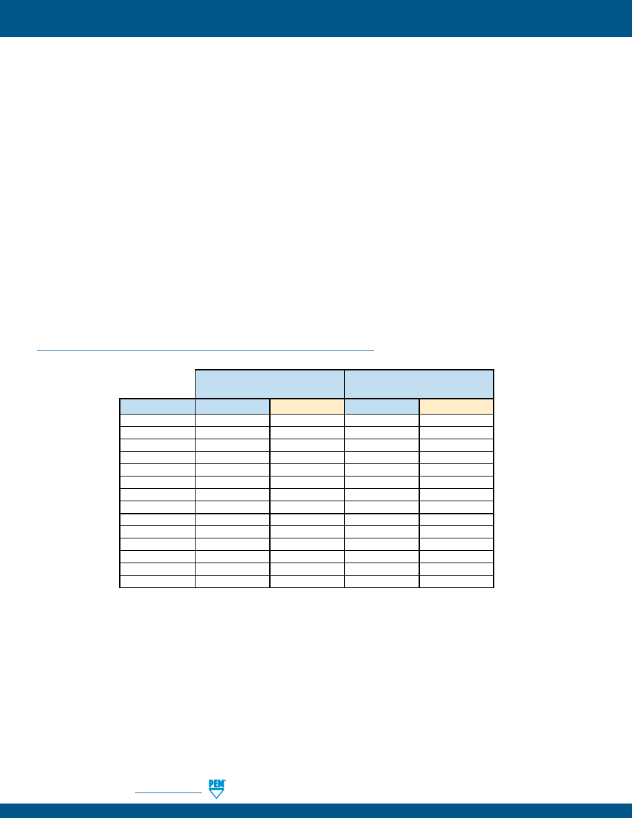
LN-22
PennEngineering •
www.pemnet.com
SELF-LOCKING FASTENERS
NASM25027 AS APPLIED TO PEM® SELF-CLINCHING, SELF-LOCKING NUTS
PEM FE, FEO, LAS, LAC, LA4, LK, LKS, LKA, PL and PLC locknuts are produced to meet the prevailing locking torque
requirements of NASM25027. Specification NASM25027 is a rather lengthy spec which includes many requirements
for attributes such as tensile strength and wrenching strength which are not applicable to PEM self-clinching, self-
locking nuts. It is difficult for those not familiar with the specification to determine exactly which portions of it apply
to the locking torque of PEM self-clinching, self-locking nuts. This matter is further complicated by the fact that
many of the requirements in the specification that do apply, apply only to qualification and are not so called “quality
conformance inspections” which need to be applied to every lot of product. The fact of the matter is that only one
test (room ambient temperature locking torque per the first row of Table IV) needs to be applied on a regular basis
of PEM self-clinching, self-locking nuts. This requirement is defined by Table XIV and the permanent set test is not
required per footnote 1. The requirements for this test are given in Paragraphs 3.8.2.2.1 and 3.8.2.2.2. The test method
is specified in paragraphs 4.5.3.3. and 4.5.3.3.4.1. For convenience of those who do not have access to this specification
and/or are not familiar with specification language, these test requirements and test methods are re-stated below in
layman’s terms.
The one required test is a 15 cycle re-usability test. There are two values of torque which are required by specification.
The first is a maximum torque value which dare not be exceeded anytime during the 15 installation and removal cycles.
The second is a minimum breakaway torque which must be met during the 15th removal cycle. These torque values
are shown in Table III of specifications NASM25027. They are also listed below for PEM fastener sizes only and also
for metric sizes.
Details of the test procedure and significant definitions can be found on our web site at:
http://www.pemnet.com/files/design_info/techsheets/NASM25027.pdf
Maximum Locking Torque
Minimum 15th Cycle
(Any Cycle)
Breakaway Torque
Thread Size
in. lbs.
N•m
in. lbs.
N•m
#2-56
2.5
0.28
0.2
0.023
#4-40
5
0.57
0.5
0.057
#6-32
10
1.13
1.0
0.113
#8-32
15
1.7
1.5
0.17
#10-24
18
2.03
2.0
0.226
#10-32
18
2.03
2.0
0.226
1/4-20
30
3.39
4.5
0.509
1/4-28
30
3.39
3.5
0.396
M2.5
3.8
0.43
0.38
0.043
M3
5
0.56
0.5
0.056
M3.5
10
1.13
1.0
0.113
M4
15
1.7
1.5
0.17
M5
18
2.03
2.0
0.22
M6
28.3
3.2
3.3
0.37
pem-html.html
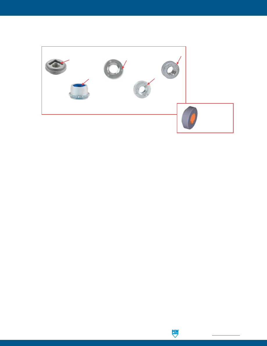
SELF-LOCKING FASTENERS
PennEngineering •
www.pemnet.com
LN-23
PEM® Blue Nylon
Locking Element
(Registered Trademark)
PEM® Double Squares
(Registered Trademark)
PEM® Stamp
(Registered Trademark)
To be sure that you are getting genuine PEM
®
brand fasteners,
look for the unique PEM product markings and identifiers.
PEM® TRI-DENT®
Locking Feature
(Trademark)
PEM® RT Stamp
(Trademark)
Fastener drawings
and models are
available at
www.pemnet.com
pem-html.html

All PEM® products meet our stringent quality standards. If you require additional industry or other specific
quality certifications
, special procedures and/or part
numbers are required. Please contact your local sales office or representative for further information.
Regulatory
compliance information
is available in Technical Support section of our website. Specifications subject to change without notice. See our website for the
most current version of this bulletin.
North America:
Danboro, Pennsylvania USA
•
E-mail:
info@pemnet.com
•
Tel: +1-215-766-8853
•
800-237-4736 (USA)
Europe:
Galway, Ireland
•
E-mail:
europe@pemnet.com
•
Tel: +353-91-751714
Asia/Pacific:
Singapore
•
E-mail:
singapore@pemnet.com
•
Tel: +65-6-745-0660
Shanghai, China
•
E-mail:
china@pemnet.com
•
Tel: +86-21-5868-3688
Visit our PEMNET™ Resource Center at
www.pemnet.com
•
Technical support e-mail:
techsupport@pemnet.com
LN-24
SELF-LOCKING FASTENERS
pem-html.html

MPF
™
PEM® brand microPEM® fasteners
are ideal for today’s and tomorrow’s
compact electronics
Bulletin MPF-817
Rev 218
pem-html.html
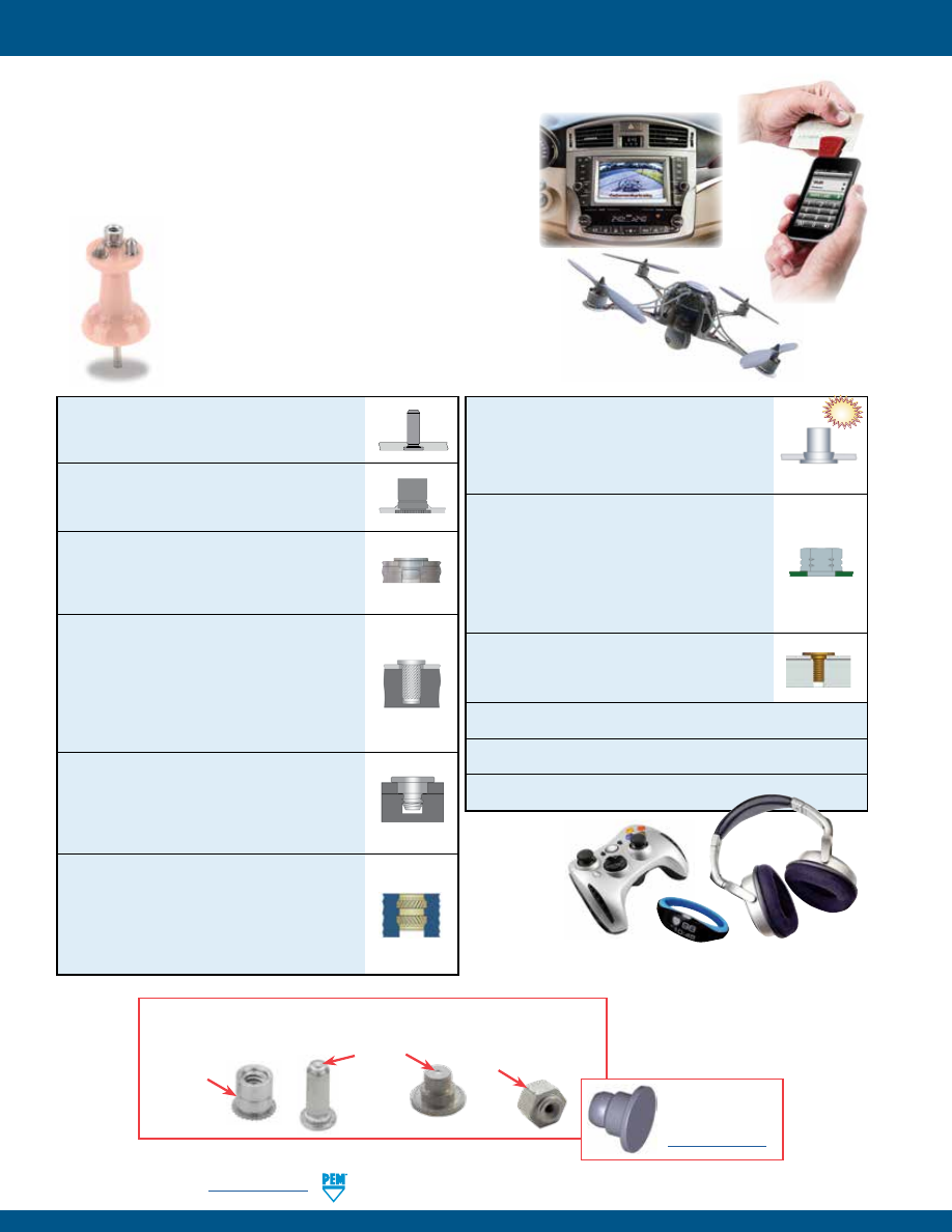
MPF-2
PennEngineering •
www.pemnet.com
microPEM® FASTENERS
IDEAL FOR TODAY’S AND TOMORROW’S COMPACT ELECTRONICS
•
Wearables (smart watches, cameras, fitness bands, headphones, etc.)
•
Laptops
•
Tablets/eReaders
•
Cell/Smart Phones
•
Gaming/Hand Held Devices/Virtual Reality
•
Infotainment/Automotive Electronics
•
Thread code as small as M0.8.
•
Pin diameters as small as 0.7 mm.
•
Standoff lengths as short as .028” / 0.7 mm.
•
Clinches flush into sheets as thin as .012” / 0.3 mm.
•
Attach sheets as thin as .008” / 0.2 mm.
Parts for smaller and/or thinner applications have been
designed. Please contact us for more information.
MPP™ microPEM® Self-clinching Pins
Ideal for micro positioning and alignment
applications -
PAGE 3
MSO4™ microPEM® Self-clinching Standoffs
Designed for mounting and/or spacing in
extremely limited space applications -
PAGE 3
TA™/T4™ microPEM® TackPin® Fasteners
Enable sheet-to-sheet attachment, replacing
costly screw installation in applications where
disassembly is not required -
PAGE 4
TKA™/TK4™ microPEM® TackSert® Pins
Designed with diagonal knurl to hold a top panel
to a bottom panel or chassis by broaching into
the bottom panel/chassis. Type TKA pins are
suitable for broaching into plastic applications,
and Type TK4 pins are suitable for broaching
into castings and brittle materials -
PAGE 5
TS4™ microPEM® TackScrew™ Fasteners
Enable cost effective sheet-to-sheet attachment
by simply pressing into place. Can be removed
by simply unscrewing, similar to other threaded
fasteners -
PAGE 6
MSIA™/MSIB™ microPEM® Inserts For Plastics
Designed for use in straight or tapered holes.
The symmetrical design eliminates the need
for orientation. They are installed by pressing
them into the mounting hole with ultrasonic
equipment or with a thermal press -
PAGE 7
MSOFS™ microPEM® Flaring Standoffs
Attach permanently in any type of panel,
including metal, plastic and P.C. Board. Flaring
feature allows for installation into multiple
panels -
PAGE 8
SMTSO™ microPEM® Surface Mount Fasteners
These fasteners for compact electronic
assemblies attach to P.C. Boards for nut/standoff
applications. These fasteners mount on P.C.
Boards in the same manner and at the same
time as other surface mount components prior to
the automated reflow solder process -
PAGE 9
microPEM® Screws
Available in sizes as small as M0.8 and lengths
as short as 1 mm / .039” -
PAGE 10
Material and finish specifications -
PAGE 11
Installation -
PAGES 12 - 14
Performance data -
PAGES 15 - 16
© 2017 PennEngineering.
To be sure you are getting genuine PEM® brand fasteners, look for the unique
PEM product markings and identifiers
Dimple
(Registered
trademark)
Single
Groove
(Registered
trademark)
Double Notch
(Registered trademark)
Fastener drawings
and models are
available at
www.pemnet.com
NEW!
pem-html.html
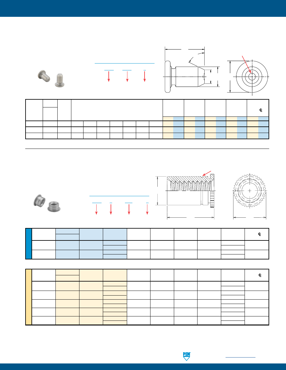
PennEngineering •
www.pemnet.com
MPF-3
microPEM® FASTENERS
MPP™ microPEM® SELF-CLINCHING PINS
Type
Hole Size
Min.
Pin Pin
Min.
In Sheet D
H Distance
Diameter Stainless Diameter
Length Code “L” ± 0.15 mm
Sheet
+0.025 mm /
±0.1 mm /
±0.25 mm / Hole
C/L
P
Steel
Code
(Length Code in millimeters)
Thickness
+.001”
±.004”
±.01”
to Edge
±0.038mm
mm in. mm in. mm in. mm in. mm in.
1
MPP 1MM 2
3
4
5
–
–
– 0.5 .02 1.05 .041 0.7 .028 1.6 .063 2.05 .081
1.5
MPP 1.5MM –
3
4
5
6
8
–
0.5 .02 1.55 .061 1.03 .041 2.24 .088 2.6 .102
2
MPP 2MM
– – 4 5 6 8 10
0.5
.02
2.05
.081
1.36
.054
3.02
.119
4.4
.173
•
Satisfy demanding micro positioning and alignment applications.
•
Head mounts flush into panels as thin as 0.5 mm / .02”.
•
Chamfered end makes mating hole alignment easy.
•
Can be installed into stainless steel sheets.
•
Excellent corrosion resistance.
•
Can be installed automatically.
MPP – 1MM – 2
PART NUMBER DESIGNATION
Type &
Material
Pin Diameter
Code
Length
Code
U
NIF
IE
D
Type
Min.
Hole
Size
Min. Dist.
Thread
Thread
Length
Sheet
In Sheet
C
H
L
Hole
C/
Size Stainless Steel
Code
Code
Thickness
+.002 -.000
Max.
Nom.
+.002 –.003
To Edge
.060-80
MSO4 080 3 .012 .095 .094 .125 .094
.090
(#0-80)
(2)
4 .125
.086-56
MSO4 256 3 .012 .125 .124 .156 .094 .120
(#2-56)
(2)
4 .125
All dimensions are in inches.
All dimensions are in millimeters.
ME
TR
IC
Type
Min.
Hole
Size
Min. Dist.
Thread Thread
Length
Sheet
In
Sheet C H L Hole
C/
Size Stainless Steel
Code
Code
Thickness
+0.05
Max.
Nom.
+0.05 – 0.08
To Edge
M1 x 0.25
(3)
MSO4
M1 2 0.3 2.41 2.39 3.18 2
2.3
3 3
M1.2 x 0.25
(3)
MSO4
M1.2 2 0.3 2.41 2.39 3.18 2 2.3
3 3
M1.4 x 0.3
(4)
MSO4
M1.4 2 0.3 2.41 2.39 3.18 2 2.3
3 3
M1.6 x 0.35
(5)
MSO4
M1.6 2 0.3 2.41 2.39 3.18 2 2.3
3 3
M2 x 0.4
(5)
MSO4
M2 2 0.3 3.18 3.16 3.96 2 3
3 3
MSO4™ microPEM® SELF-CLINCHING STANDOFFS
(1) MSO4 standoffs are designed for use in sheet hardness HRB 88 / HB 183 or less. For installation into harder sheets (up to HRC 36), contact our Tech
Support line or your local representative.
(2) Unified ASME B1.1, 2B
(3) Miniature ISO 68-1, 5H
(4) Miniature ISO 68-1, 6H
(5) Metric ASME B1.13M, 6H
MSO
4 – 080 – 3
PART NUMBER DESIGNATION
Type
Thread
Code
Length
Code
Material
Code
•
Designed for mounting and/or spacing in extremely limited space applications.
•
Can be installed into stainless steel sheets.
(1)
•
Have stronger threads than weld standoffs because they are
made from heat-treated 400 Series Stainless Steel.
•
Can be installed automatically.
H
L
64° Nom.
P
D
Look for the PEM “Dimple”
registered trademark
Clinching profile may vary.
H
L
C
Look for the “single groove” trademark
Clinching profile may vary.
pem-html.html
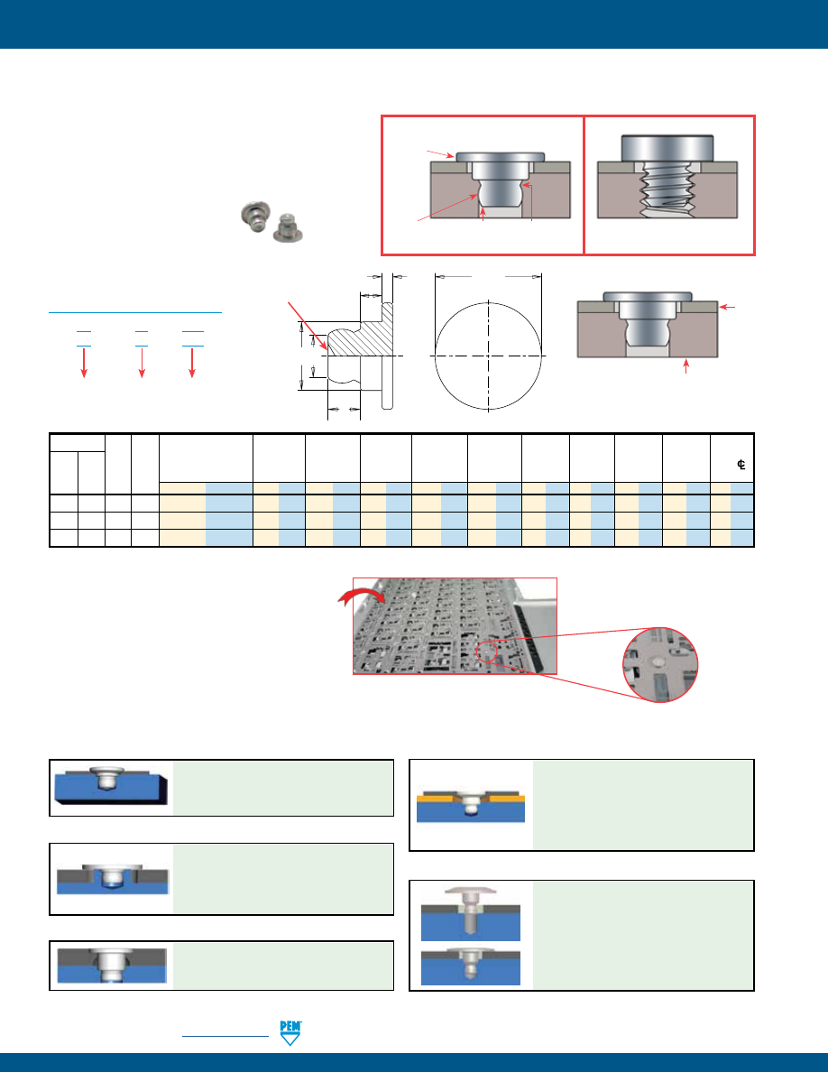
MPF-4
PennEngineering •
www.pemnet.com
microPEM® FASTENERS
Type Base Top
Base
Top Sheet
Base Panel
Min.
Panel Sheet
Top
Panel
Hole Size
Hole Size
A
B
C
H
P
T
Dist.
Stain- Hole Thick-
Sheet
Min. Sheet
±0.05 mm /
-0.05 mm /
±0.025 mm /
±0.075 mm /
Max.
±0.1 mm / ±0.05 mm / ±0.1 mm /
Hole
CL
Alumi- less Size ness
Thickness
Thickness
(1)
±.002”
-.002”
±.001”
±.003”
±.004”
±.002”
±.004”
To Edge
num Steel Code Code mm
in.
mm in. mm in. mm in. mm in. mm in. mm in. mm in. mm in. mm in. mm in.
TA T4 10 025 0.2-0.28 .008-.011 0.89 .035 1.47 .058 1.02 .040 0.406 .016 0.610 .024 0.89 .035 2 .079 1.3 .051 0.2 .008 1 .039
TA T4 10 050 0.48-0.56 .019-.022 0.89 .035 1.47 .058 1.02 .040 0.686 .027 0.610 .024 0.89 .035 2 .079 1.3 .051 0.2 .008 1 .039
TA –
10 075 0.71-0.79 .028-.031 0.89 .035 1.47 .058 1.02 .040 0.914 .036 0.610 .024 0.89 .035 2 .079 1.3 .051 0.2 .008 1 .039
(1) 0.89 mm / .035” for blind holes and 0.5 mm / .020” for through holes.
Base panel.
TackPin fastener installs into blind or
through hole applications.
Top
sheet
TA – 10 – 025
T4 – 10 – 025
PART NUMBER DESIGNATION
Type &
Material
Base Panel
Hole Size
Code
Top Sheet
Thickness
Code
•
Advantages over micro screws: eliminates costly
tapping, cross threading, torque control, vibration
back-out and installation time.
•
Interference fit minimizes hole tolerance issues.
•
Tapered tip assists location.
•
Low-profile head provides space savings.
•
Top sheet can be any material.
•
Can be installed automatically.
TA™/T4™ microPEM® TackPin® FASTENERS
Interference fit
eliminates hole
tolerance
Tapered
tip assists
location
Positive engagement,
360˚ metal contact. Will
not loosen.
Low-profile
head
With TackPin® Fastener
With Screw
Typical screw related issues include
costly tapping, cross-threading, torque
control, and vibration back-out.
Comparison of TackPin® fastener to screw installation.
Patented.
In one notable application, TackPin® fasteners
have been specified to replace screws to
attach a super-thin membrane to a very
thin substrate in keyboards. The switch to
TackPin® fasteners significantly reduced
assembly costs.
Thin Sheet TackPin™ Fastener
Countersunk TackPin® Fastener
CUSTOM microPEM® TackPin® FASTENER SOLUTIONS
•
Installs into a countersunk hole,
replacing countersunk screws.
•
Offers flush or near flush appearance.
•
Simple, press-in installation.
•
Enables sheet-to-sheet attachment of
multiple layers.
•
Flush or sub-flush on both sides of sheet.
•
Head mounts flush into top sheets as
thin as .008” / 0.2 mm.
H
B
P C
T
A
PEM® “Dimple”
registered trademark
Clinching profile may vary.
•
TackPin with a large head installed
into boss of bottom panel.
•
Holds down top panel that is free to
rotate around the boss.
Large Head TackPin® Fastener
•
TackPin installed into a thicker, softer
top-sheet and pressed flush.
Flush-head TackPin® Fastener
FlexTack™ Fastener
•
The belleville shaped head flattens
upon a simple press-in installation.
•
Draws panels together to
accomodate vertical stack tolerances.
pem-html.html
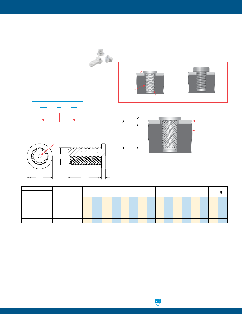
PennEngineering •
www.pemnet.com
MPF-5
microPEM® FASTENERS
TKA™/TK4™ microPEM® TackSert® PINS
•
Secure panels to common cast materials such as magnesium and aluminum. Also appropriate for attaching panels to plastics
such as ABS and to P.C. Boards.
•
Simple, press-in installation. Does not require heat or ultrasonics.
•
Alternative to micro screws, eliminating the need to tap or use threaded inserts.
•
Top sheet can be any material.
•
Low-profile head.
•
Eliminates the following:
–
Cost of screw
–
Cost of patch to prevent loosening
–
Cost of threaded insert or tapped hole
–
Cost of driver bits
–
Cost of rework due to cross-threading and
driver bit “cam-out”.
•
Can be installed automatically.
TKA – 10 – xxx
TK4 – 10 – xxx
PART NUMBER DESIGNATION
Type &
Material
Base Panel
Hole Size
Code
Length
Code
Type
Base
Top Sheet
Base Panel
Top Sheet
H
L
T
Min. Dist.
Fastener Material
Panel
Hole Size
Hole Size
Thickness
C
±0.08 mm/
±0.06 mm/
±0.08 mm/
Hole
CL
Aluminum
400 series
Hole Size
Length
±0.05 mm/±.002” -0.05 mm/-.002”
Max.
Max.
±.003”
±.002”
±.003”
To Edge
(1)
stainless steel
Code
Code
mm in. mm in. mm in. mm in. mm in. mm in. mm in. mm in.
TKA
TK4
10
100
1.3 .051 1 .039 0.2 .008 1.2 .047 1.8 .071 1 .039 0.27 .011 1.18 .047
TKA
TK4
10
150
1.3 .051 1 .039 0.7 .028 1.2 .047 1.8 .071 1.5 .059 0.27 .011 1.18 .047
TKA
TK4
10
200 1.3 .051 1 .039 1.2 .047 1.2 .047 1.8 .071 2 .079 0.27 .011 1.18 .047
TKA
TK4
10
250
1.3 .051 1 .039 1.7 .067 1.2 .047 1.8 .071 2.5 .098 0.27 .011 1.18 .047
TKA
TK4
10
300
1.3 .051 1 .039 2.2 .087 1.2 .047 1.8 .071 3 .118 0.27 .011 1.18 .047
(1) Minimum boss diameter is twice centerline-to-edge value.
For through hole applications
DOE - 0.25 mm / .010” = Min. Sheet
For blind hole applications
DOE + 0.25 mm / .010” = Min. Blind Hole Depth
Base panel.
TackSert pin shown
installed into blind
hole application.
Top sheet.
Top Sheet Thickness
(TST)
Depth Of
Engagement
(DOE)
DOE = L - TST
DOE > 0.8 mm / .0315”
L
Broaching
knurl creates
a firm interference fit
Tapered tip
assists location
Low-profile
head
With TackSert® Pin
With Screw
Typical screw related issues include costly
tapping, cross-threading, torque control, and
vibration back out.
Comparison of TackSert® pin to screw installation.
H
C
T
L
PEM® “Dimple”
registered trademark
pem-html.html
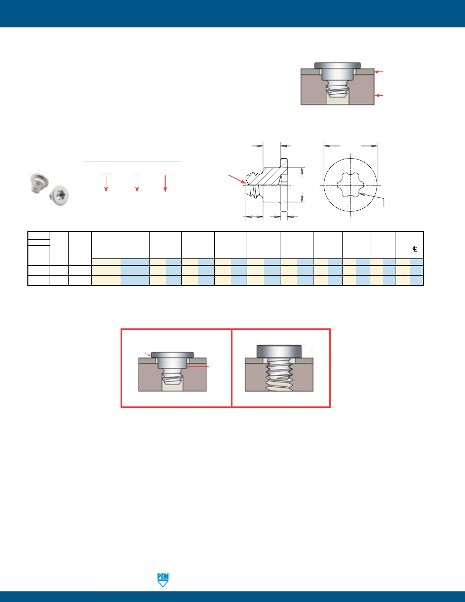
MPF-6
PennEngineering •
www.pemnet.com
microPEM® FASTENERS
Type Base
Base
Top Sheet
Base Panel
Min.
Material
Panel
Top
Top
Panel
Hole Size
Hole Size
A
H
L
P
T
Dist.
Hardened Hole
Sheet
Sheet
Min. Sheet
±0.05 mm /
±0.025 mm /
±0.05 mm /
±0.1 mm /
±0.1 mm /
±0.05 mm /
±0.1 mm /
Hole
CL
Stainless Size Thickness
Thickness
Thickness
(1)
±.002”
±.001”
±.002”
±.004”
±.004”
±.002”
±.004”
To Edge
Steel Code Code
mm
in. mm in. mm in. mm in. mm in. mm in. mm in. mm in. mm in. mm in.
TS4
10
025
0.2 - 0.28
.008 - .011
0.91 .036
1.47
.058
0.99 .039 0.406 .016
2
.079 0.64 .025 1.3 .051 0.25 .010
1
.039
TS4
10
050
0.48 - 0.56
.019 - .022
0.91 .036
1.47
.058
0.99 .039 0.686 .027
2
.079 0.64 .025 1.3 .051 0.25 .010
1
.039
TackScrew fastener installs into blind
or through hole applications.
Top
sheet
Base
panel
(1) Minimum sheet to prevent protrusion from through hole or minimum blind hole depth.
TS4™ microPEM® TackScrew™ FASTENERS
•
Simple, press-in installation for secure attachment.
•
Proven self-clinching technology resists vibrational loosening.
•
Replaces micro screws, eliminating installation issues including:
–
Cost of locking patch
–
Cost of threaded insert or tapped hole
–
Cost of driver bits
–
Cost of rework due to cross-threading and driver bit “cam-out”
•
Top sheet can be any material.
•
Can be installed automatically.
•
Twists out (unscrew) if removal is necessary. Can be reinstalled one time
using a thread locking adhesive.
TS4 – 10 – 025
PART NUMBER DESIGNATION
Type &
Material
Base Panel
Hole Size
Code
Top Sheet
Thickness
Code
With TackScrew™ Fastener
With Screw
Comparison of TackScrew™ fastener to screw installation.
Low-profile head
Typical screw related issues include costly tapping,
cross-threading, torque control, and vibration back out.
Clinches
into base
panel
H
A
P
L
2IP Torx Plus driver
T
PEM® “Dimple”
registered trademark
pem-html.html
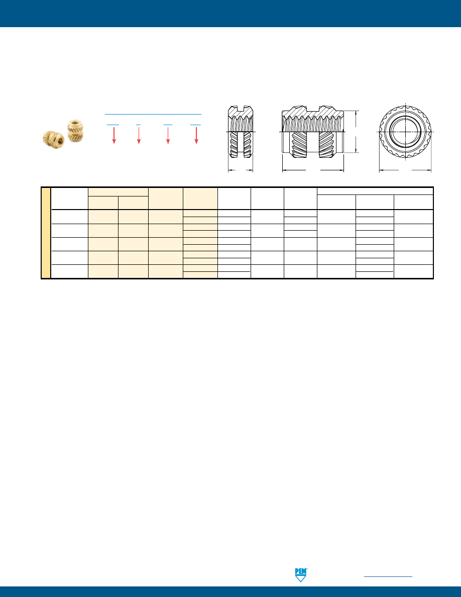
PennEngineering •
www.pemnet.com
MPF-7
microPEM® FASTENERS
MSIA™/MSIB™ microPEM® INSERTS FOR PLASTICS
•
Threads as small as M1.
•
Symmetrical design eliminates the need for orientation.
•
Provides excellent performance in wide range of plastics.
•
Aluminum inserts offer light weight, lead-free alternative.
(1)
Style #1
- length codes less than 150
(2)
Style #2
- length codes 150 and greater
(3) Metric ISO 68-1, 5H
(4) Metric ISO 68-1, 6H
(5) Metric ASME B1.13M, 6H
(6) Refers to wall thickness of boss as tested in ABS and polycarbonate.
Style #1
Style #2
A
C
E
A
After Knurl
MSI
B – M1 – 100
PART NUMBER DESIGNATION
Type
Thread
Size Code
Length
Code
Material
All dimensions are in millimeters.
ME
TR
IC
Thread Type
Size x
New
Brass
Thread Length A
E
C Min. Wall
Hole Depth
Hole Diameter
Pitch Aluminum
Code
Code
±0.1
± 0.1
Max.
Thickness
(6)
Min. +0.05
M1 x 0.25
(3)
MSIA MSIB
M1
100
(1)
1 2.1 — 0.7
1.77
1.75
250
(2)
2.5 1.75
3.27
M1.2 x 0.25
(3)
MSIA MSIB
M1.2
100
(1)
1 2.1 — 0.7
1.77
1.75
250
(2)
2.5 1.75
3.27
M1.4 x 0.3
(4)
MSIA MSIB M1.4
150
(2)
1.5 2.5 2.15 0.8 2.27
2.15
300
(2)
3
3.77
M1.6 x 0.35
(5)
MSIA MSIB
M1.6
150
(2)
1.5 2.5 2.15 0.8 2.27
2.15
300
(2)
3
3.77
M2 x 0.4
(5)
MSIA MSIB M2
300
(2)
3 3.2 2.85 1.6 3.77
2.85
400
(2)
4
4.77
Mounting Hole in Material
pem-html.html
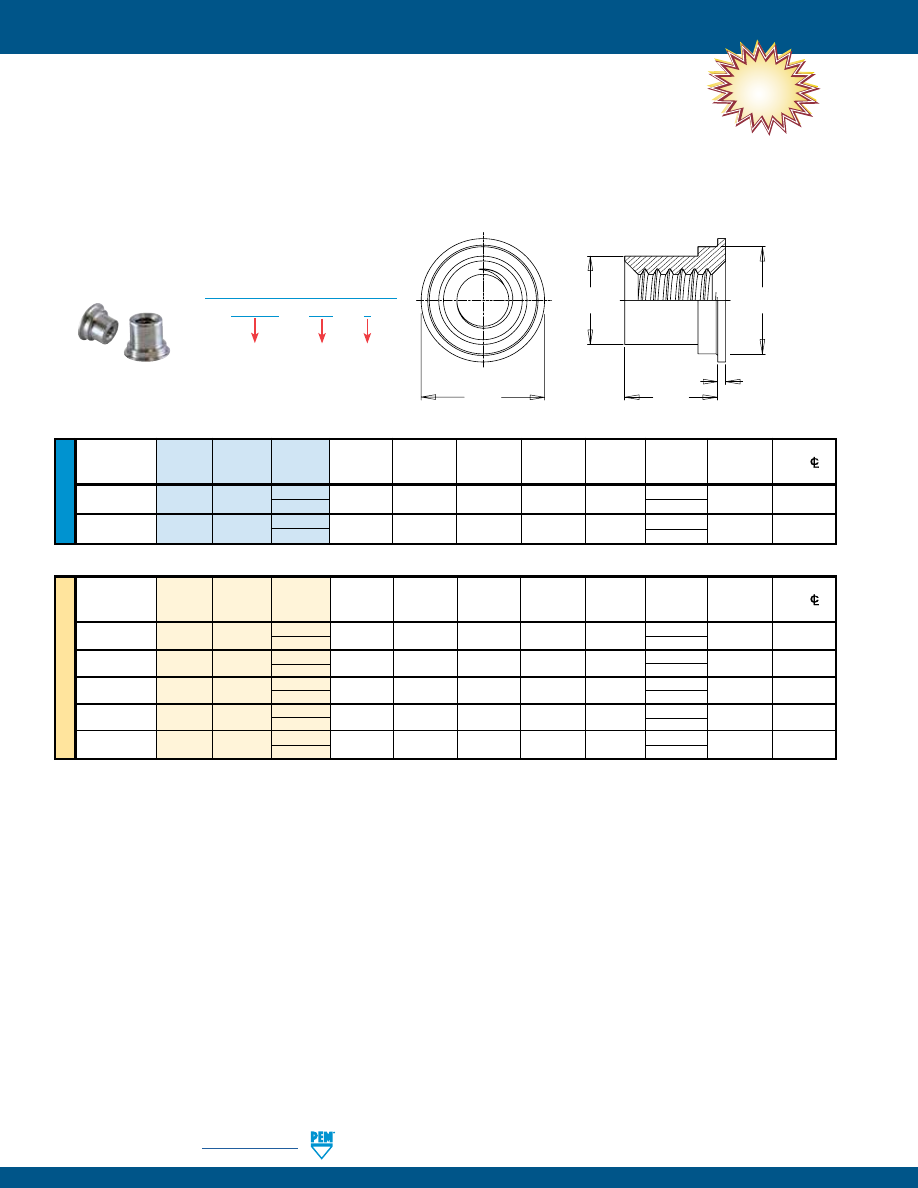
MPF-8
PennEngineering •
www.pemnet.com
microPEM® FASTENERS
NEW!
U
NIF
IE
D
Hole
Size
Min.
Dist.
Thread
Thread
Length
Sheet
in Sheet
C
D
H
L
T
Hole
CL
Size
Type Code Code
Thickness
+.002 –.000
Max.
Max.
Nom.
+.002 –.003
±.002
to Edge
.060-80
MSOFS 080
3
.008 - .012
.118
.094
.117
.138
.093 .010 .069
(#0-80)
(1)
4
.125
.086-56
MSOFS 256
3
.008 - .012
.138
.113
.137
.157
.093 .010 .079
(#2-56)
(1)
4
.125
All dimensions are in inches.
ME
TR
IC
Thread
Hole Size
Min. Dist.
Size x
Thread
Length
Sheet
in Sheet
C
D
H
L
T
Hole
CL
Pitch
Type Code Code
Thickness
+0.05
Max.
Max.
Nom.
+0.05 –0.08
±0.05
to Edge
M1 x 0.25
(2)
MSOFS M1 2
0.2 - 0.3
3
2.39
2.97
3.35 2 0.25 1.75
3 3
M1.2 x 0.25
(2)
MSOFS M1.2 2 0.2 - 0.3
3
2.39
2.97
3.35 2 0.25 1.75
3 3
M1.4 x 0.3
(3)
MSOFS M1.4 2 0.2 - 0.3
3
2.39
2.97
3.35 2 0.25 1.75
3 3
M1.6 x 0.35
(4)
MSOFS M1.6 2 0.2 - 0.3
3.5
2.87
3.48
4 2 0.25 2
3 3
M2 x 0.4
(4)
MSOFS M2 2
0.2 - 0.3
3.5
2.87
3.48
4 2 0.25 2
3 3
All dimensions are in millimeters.
H
C
T
L
D
•
New MSOFS™ microPEM® flaring standoffs attach permanently in panels as thin as
.008”/0.2 mm of any hardness, including stainless steel.
•
Can be installed into any type of panel, including metal, plastic and P.C. Board.
•
Flaring feature allows for installation into multiple panels.
•
Small footprint allows for reduced centerline-to-edge designs.
•
Threads as small as #0-80/M1.
MSOFS – 080 – 3
PART NUMBER DESIGNATION
Thread
Code
Length
Code
Type and
Material
MSOFS™ microPEM® FLARING STANDOFFS
(1) Internal, ASME B1.1, 2B
(2) Metric ISO 68-1, 5H
(3) Metric ISO 68-1, 6H
(4) Metric ASME B1.13M, 6H
pem-html.html
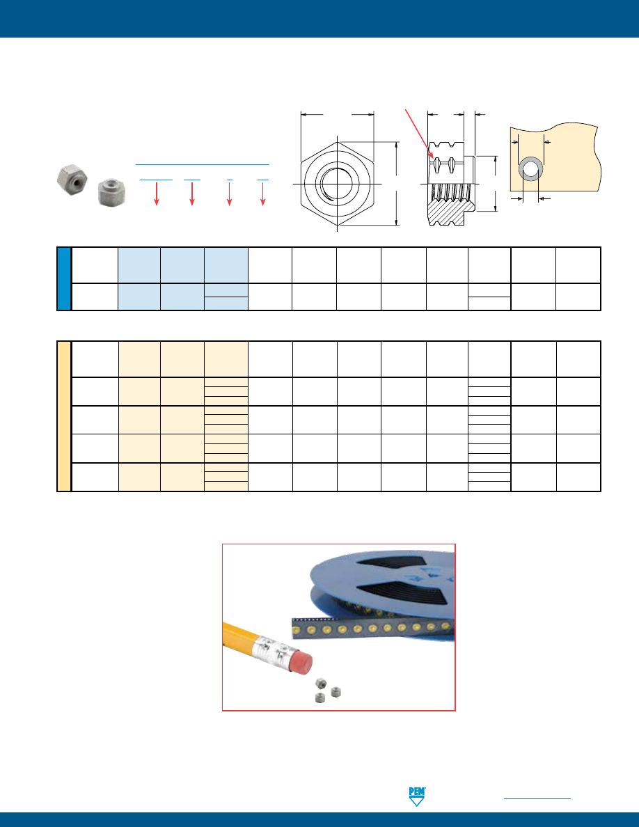
PennEngineering •
www.pemnet.com
MPF-9
microPEM® FASTENERS
U
NIF
IE
D
Min.
Ø
H Hole Size
Ø
D
Thread
Thread
Length
Sheet
A
C
E
H
L
In Sheet
Min. Solder
Size
Type
Code
Code
Thickness
Max.
Max.
Ref.
Nom.
±.003
+.003 –.000
Pad
.060-80
SMTSO 080
2
.020 .019 .095 .144 .125
.062
.098 .165
(#0-80)
(1)
4
.125
All dimensions are in inches.
ME
TR
IC
Min.
Ø
H Hole Size
Ø
D
Thread
Thread
Length
Sheet
A
C
E
H
L
In Sheet
Min. Solder
Size
Type
Code
Code
Thickness Max. Max. Ref. Nom. ±0.08 +0.08 Pad
1 1
S1
(2)
SMTSO M1
2
0.5 0.48 2.41 3.66 3.18 2
2.5 4.19
3 3
1 1
S1.2
(2)
SMTSO M1.2
2
0.5
0.48 2.41 3.66 3.18
2
2.5
4.19
3 3
1 1
S1.4
(2)
SMTSO M1.4
2
0.5
0.48 2.41 3.66 3.18
2
2.5
4.19
3 3
1 1
M1.6 x 0.35
(3)
SMTSO
M1.6
2
0.5
0.48
2.41
3.66
3.18
2
2.5
4.19
3 3
All dimensions are in millimeters.
•
Hex shaped barrel provides optimal size/performance.
•
Provided on tape and reel.
•
Reduces board handling.
•
Can be installed automatically.
Ø
H
Ø
D
Solder
Pad
Plated through hole
not required.
E
H
C
A
L
Double Notch (PEM® Registered Trademark)
Metric -1 length not marked
SMTSO™ microPEM® SURFACE MOUNT FASTENERS
SMTSO 080 – 2 – ET
PART NUMBER DESIGNATION
Type
Length
Code
Finish
Code
Thread
Code
(1) Unified ASME B1.1, 2B
(2) Miniature ISO 1501, 4H6
(3) Metric ASME B1.13M, 6H
pem-html.html
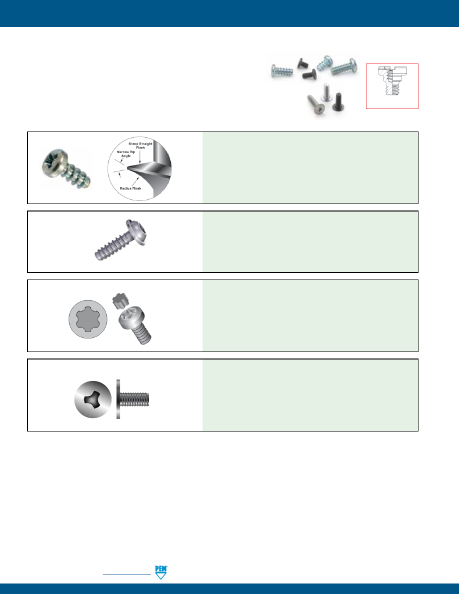
MPF-10
PennEngineering •
www.pemnet.com
microPEM® FASTENERS
microPEM® SCREWS
(Available on special order. Minimum quantities may apply)
•
Smallest thread code: M0.8.
•
Shortest length: 1 mm / .039”.
•
Fastener material: steel, stainless steel and aluminum.
•
Driver types: Torx®/Torx Plus®/Microstix®, cross-recess/internal hex.
•
Head styles: flat head/pan head/socket-head/wafer-head.
•
Special features: Locking patch, REMFORM®, TAPTITE 2000®, FASTITE 2000®, PT® and DELTA PT®
•
Platings: zinc, nickel, black nickel and black oxide.
PennEngineering is a licensee of Acument Global Technologies (Torx®, Torx Plus®), Reminc (REMFORM®, TAPTITE 2000®, FASTITE 2000®), EJOT® (PT® and DELTA PT®) and
OSG Corporation and OSG System Products Co., Ltd. (Microstix®).
TORX PLUS® DRIVE SYSTEM
•
Designed primarily for plastic applications
•
Provides superior performance in a wide range of plastics
•
Asymmetrical thread minimizes radial hoop stress to reduce boss
bursting
•
Narrow tip angle reduces stress in plastic nut member
•
Suitable for other ductile materials such as wood and soft metals
REMFORM® SCREWS
•
0˚ drive angle
•
Elliptical geometric configuration maximizes drive bit engagement
•
Large cross-sectional area at lobes
•
Vertical sidewalls
•
Optimizes torque transfer
•
Virtually eliminates cam-out
•
Reduces end load and worker fatigue
•
Reduces annual drive bit costs
•
Minimal radial tension due to optimized flank angle
•
High clamp load
•
High tensile and torsion strength
•
Increased cycle stress stability
•
High strength under vibration
DELTA PT® SCREWS
Cost-effective, forged
internal/external screw
•
No cam-out
•
No driving force
•
High workability
•
High torque transmission
•
High precision bits
•
Tamper proof
•
High durability
•
Better fit between bits and screws
MICROSTIX® ULTRA-THIN-HEAD PRECISION SCREWS
pem-html.html
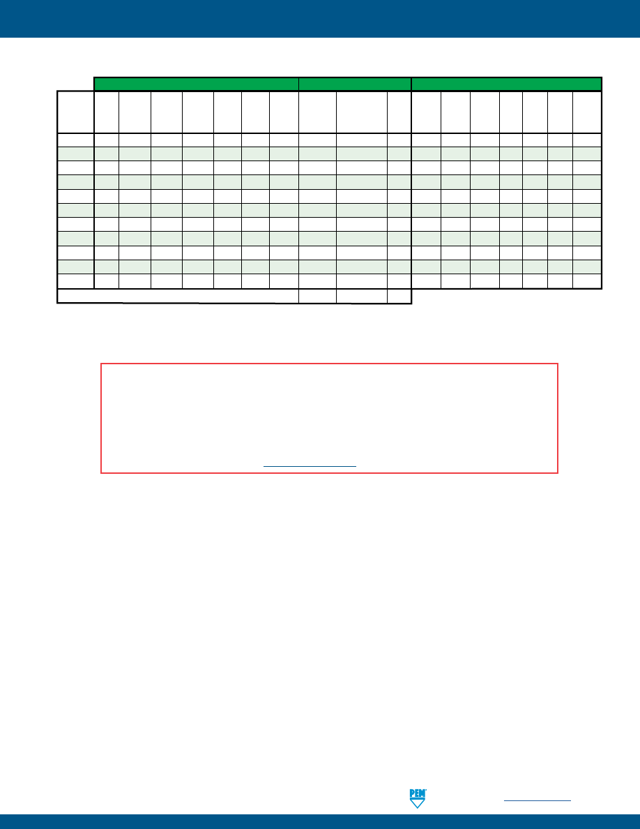
PennEngineering •
www.pemnet.com
MPF-11
microPEM® FASTENERS
MATERIAL AND FINISH SPECIFICATIONS
(1) HRB - Hardness Rockwell “B” Scale. HB - Hardness Brinell.
Fastener Materials
Standard Finishes
For Use in Sheet Hardness: (1)
Age Electro-Plated
Tin
Hardened
Hardened
Free-
Passivated
ASTM
B
545,
Castings
A286
300 Series 400 Series
Machining
and/or
Class A, with Clear
HRB 50 / HRB 88 /
HRB 92 /
and
Any
Type
Carbon
Stainless
Stainless
Stainless Hardened
Leaded
Tested Per
Preservative Coating, Plain
HB 89
HB 183
HB 202
PC
Brittle
Panel
Steel
Steel
Steel
Steel
Aluminum Aluminum
Brass
ASTM A380
Annealed
Finish
or Less
or Less
or Less
Board Plastics Materials Hardness
MPP
• •
•
MSO4
• •
•
SMTSO
•
• •
TA
•
• •
T4
• •
•
TKA
•
• •
•
TK4
• •
•
•
•
TS4
• •
•
MSIA
•
• •
MSIB
•
• •
MSOFS
• •
•
Part Number Codes For Finishes
None
ET
None
A NOTE ABOUT FASTENERS FOR STAINLESS STEEL PANELS
In order for self-clinching fasteners to work properly, the fastener must be harder than the sheet into which it is being installed. In
the case of stainless steel panels, fasteners made from 300 Series Stainless Steel do not meet this hardness criteria. It is for this
reason that 400 series fasteners are offered (Types MSO4, T4, TK4 AND TS4). However, while these 400 Series fasteners install
and perform well in 300 Series stainless sheets they should not be used if the end product:
•
Will be exposed to any appreciable corrosive presence.
•
Requires non-magnetic fasteners.
•
Will be exposed to any temperatures above 300˚F (149˚C)
If any of the these are issues, please contact
techsupport@pemnet.com
for other options.
pem-html.html
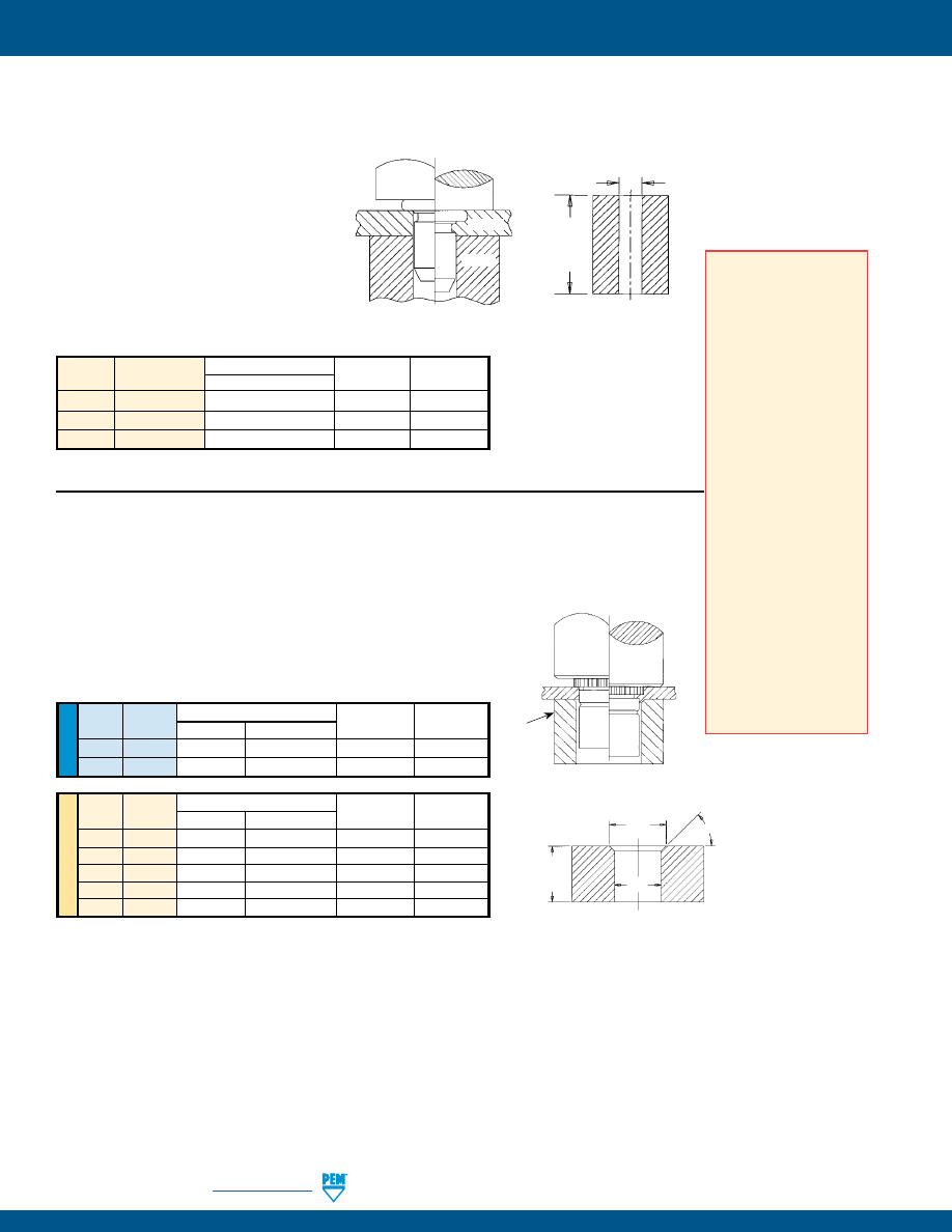
MPF-12
PennEngineering •
www.pemnet.com
microPEM® FASTENERS
MSO4 STANDOFFS
PUNCH
ANVIL
BEFORE
AFTER
U
NIF
IE
D
Thread Anvil Dimensions (inches)
Anvil Punch
Type
Code A
B
Part Number
Part Number
MSO4
080
.112 - .114
.097 - .099
8015796
975200997
MSO4
256
.142 - .144
.127 - .129
8015797
975200997
ME
TR
IC
Thread Anvil Dimensions (mm)
Anvil Punch
Type
Code A
B
Part Number
Part Number
MSO4
M1
2.84 - 2.89
2.46 - 2.51
8015796
975200997
MSO4
M1.2
2.84 - 2.89
2.46 - 2.51
8015796
975200997
MSO4
M1.4
2.84 - 2.89
2.46 - 2.51
8015796
975200997
MSO4
M1.6
2.84 - 2.89
2.46 - 2.51
8015796
975200997
MSO4
M2
3.6 - 3.65
3.22 - 3.27
8015797
975200997
1.
Prepare properly sized mounting hole
in sheet. Do not perform any secondary
operations such as deburring.
2.
Insert pin through mounting hole
(preferably the punch side) of sheet and
into anvil hole.
3.
With installation punch and anvil surfaces
parallel, apply squeezing force to embed
the head of the pin flush in the sheet.
Type
Pin Diameter
Anvil Dimensions (mm)
Anvil Punch
Code
B ±0.02
Part Number
Part Number
MPP
1MM
1.07
8014168
8014167
MPP
1.5MM
1.57
8014169
8014167
MPP
2MM
2.07
8014170
8014167
MPP PINS
INSTALLATION
1.
Prepare properly sized mounting hole in sheet. Do not perform any
secondary operations such as deburring.
2.
Insert standoff through mounting hole (preferably the punch side) and
into anvil as shown in drawing.
3.
With installation punch and anvil surfaces parallel, apply only enough
squeezing force to embed the head of the standoff flush in the sheet.
B
L*
+3.18 mm/
.125” Min.
Recommended Installation Anvil
SHEET
ANVIL
PUNCH
BEFORE
AFTER
Requirements for
Installation into
Stainless Steel
1. Sheet hardness must
be less than the
specified limit for the
fastener.
2. Panel material should
be in the annealed
condition.
3. Fastener should be
installed in punch side
of hole.
4. Mounting hole punch
should be kept sharp
to minimize work
hardening around hole.
5. Maintain the mounting
hole punch diameter
to no greater than
.025 mm / .001”
over the minimum
recommended
mounting hole.
6. When installing
fastener adjacent to
bends or other highly
cold-worked areas, use
the C/L to edge values
listed in the catalog.
Recommended Installation Anvil
A
B
45˚
Nom.
L*
+.125”/
3.18 mm
Min.
*See page 3
for “L”.
*See page 3
for “L”.
PEMSERTER®
Installation Tooling
PEMSERTER®
Installation Tooling
pem-html.html
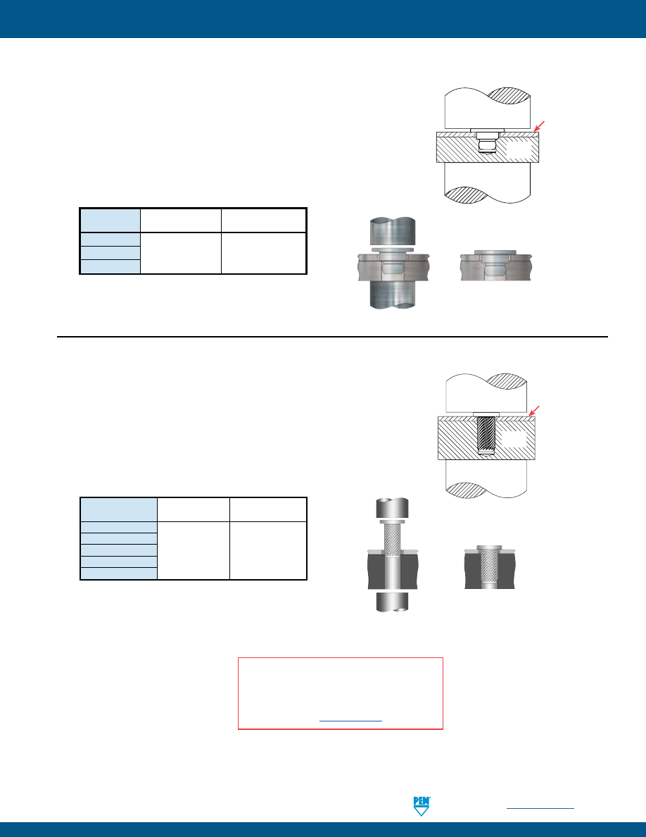
PennEngineering •
www.pemnet.com
MPF-13
microPEM® FASTENERS
TA/T4 FASTENERS
Size
Manual Punch
Manual Anvil
Part Number
Part Number
TA/T4-10-025
TA/T4-10-050
8014167
975200046
TA/T4-10-075
1.
Prepare properly sized mounting hole in top sheet and base panel.
Base panel mounting hole can be through or blind.
2.
Place top sheet and base panel in proper position.
3.
Place fastener through hole in top sheet and into mounting hole
(preferably the punch side) of base panel.
4.
With installation punch and anvil surfaces parallel, apply squeezing
force until the head of the fastener contacts the top sheet.
microPEM® TackPin® fasteners can be installed automatically in
high volume applications. Contact your nearest Engineering
representative for more information.
BEFORE PRESSING
AFTER PRESSING
Shown with through mounting hole
PUNCH
ANVIL
Top Sheet
Shown with
blind mounting
hole
Base
Panel
INSTALLATION
Size
Punch Anvil
Part Number
Part Number
TKA/TK4-10-100
TKA/TK4-10-150
TKA/TK4-10-200
8014167
975200046
TKA/TK4-10-250
TKA/TK4-10-300
BEFORE PRESSING
AFTER PRESSING
Shown with through mounting hole
TKA/TK4 PINS
1.
Prepare properly sized mounting hole in top sheet and base panel.
Base panel mounting hole can be through or blind.
2.
Place top sheet and base panel in proper position.
3.
Place pin through hole in top sheet and into mounting hole of base
panel.
4.
With installation punch and anvil surfaces parallel, apply squeezing
force until the head of the pin contacts the top sheet.
PEMSERTER®
Installation Tooling
PEMSERTER®
Installation Tooling
microPEM® TackSert® fasteners can be installed automatically
in high volume applications. Contact your nearest Engineering
representative for more information.
PUNCH
ANVIL
Top Sheet
Base
Panel
Shown with
blind mounting
hole
INSTALLATION NOTES
•
For best results we recommend using a PEMSERTER®
press for installation of PEM self-clinching fasteners.
Please check our website for more information.
•
Visit the Animation Library on our website to view the
installation process
for select products
.
pem-html.html

MPF-14
PennEngineering •
www.pemnet.com
microPEM® FASTENERS
SMTSO FASTENERS
Solder paste applied
to pad on PCB.
Solder fastener in place
using standard surface
mount techniques.
Polyimide patch applied here for
vacuum pick up.
Thread
Length Code
Code
1 2 3 4
080
—
3500 / 8
—
2000 / 8
M1, M1.2, M1.4, M1.6
3500 / 8
2500 / 8
2000 / 8
—
Number of parts per reel/pitch (mm) for each size
Packaged on 330mm recyclable reels.
Tape width is 16mm.
Supplied with polyimide patch for vacuum pick up.
Reels conform to EIA-481.
TS4 FASTENERS
1.
Prepare properly sized mounting hole in top
sheet and base panel. Base panel mounting
hole can be through or blind.
2.
Place sheet and base panel in proper position.
3.
Place fastener through hole in sheet and into
mounting hole (preferably the punch side) of
base panel.
4.
With punch and anvil surfaces parallel, apply
squeezing force until the head of the fastener
contacts the top sheet.
Re-installation (if necessary)
1.
Place sheet and base panel in proper position.
2.
Place adhesive into base panel mounting hole.
3.
Place fastener through hole in top sheet and
into mounting hole of base panel.
4.
Screw in fastener with 2IP Torx Plus driver.
PEMSERTER®
Installation Tooling
Part Number
Punch
Anvil
Part Number
Part Number
TS4-10-025
8014167 975200046
TS4-10-050
INSTALLATION
BEFORE PRESSING
PUNCH
ANVIL
Shown with blind mounting hole.
Can also be used with a through hole.
1.47 mm / .058”
± 0.05 mm / ± .002”
0.91 mm / .036”
Min.
0.99 mm / .039”
± 0.025 mm / ± .001”
Top Sheet
Thickness
AFTER PRESSING
PUNCH
ANVIL
U
NIF
IE
D
PEMSERTER® Installation Tooling
MSOFS STANDOFFS
1.
Prepare properly sized mounting hole in
sheet. Do not perform any secondary
operations such as deburring.
2.
Place the standoff into anvil recess and
place the mounting hole over the standoff
as shown in the drawing.
3.
Using a punch flaring tool and a recessed
anvil, apply squeezing force until punch
contacts the sheet.
Thread
Punch Dimensions (in.) Anvil Dimensions (in.)
Code
C
Punch Part
A
B
Anvil Part
+.001
Number ±.001 ±.001 Number
080
.095
8020712 .143 .006 8019720
256
.114
8020710
.163
.006
8019722
ME
TR
IC
Thread
Punch Dimensions (mm) Anvil Dimensions (mm)
Code
C
Punch Part
A
B
Anvil Part
+0.025
Number ±.025 ±.025 Number
M1
2.41
8020712 3.64 0.15 8019720
M1.2
2.41
8020712
3.64
0.15
8019720
M1.4
2.41
8020712
3.64
0.15
8019720
M1.6
2.9
8020710
4.14
0.15
8019722
M2
2.9
8020710
4.14
0.15
8019722
BEFORE
AFTER
PUNCH DETAIL
ANVIL DETAIL
A
B
Punch
Anvil
C
Ø .250”/
6.35 mm Min.
15
˚
Nom.
.004” ±.001”/
0.1 mm ±0.25 mm
pem-html.html
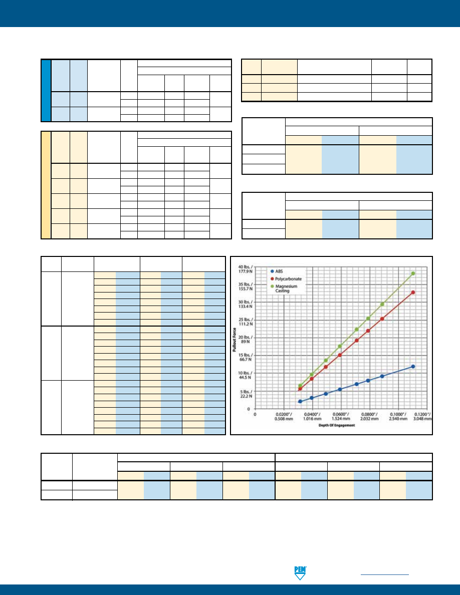
PennEngineering •
www.pemnet.com
MPF-15
microPEM® FASTENERS
5052-H34 Aluminum HRB 63 / HB 114
304 Stainless Steel HRB 89 / HB 187
Part
Tested
Installation
Pullout
(3)
Torque to Remove
Installation
Pullout
(3)
Torque to Remove
Number
Top Sheet
Thickness
(N) (lbs.) (N) (lbs.)
(N•cm)
(in.
oz.) (N) (lbs.) (N) (lbs.) (N•cm)
(in.
oz.)
TS4-10-025
0.254 mm / .01”
556 125 80 18 3.3 4.7 1423 320 125 28 4.6 6.5
TS4-10-050
0.533 mm / .021”
TS4 FASTENERS
ME
TR
IC
PERFORMANCE DATA
(1)
Type
Pin Diameter
Test Sheet Thickness
Installation Pushout
Code
(kN)
(N)
MPP
1MM
0.5mm stainless steel HRB 88
10
320
MPP
1.5MM
0.5mm stainless steel HRB 88
12
760
MPP
2MM
0.5mm stainless steel HRB 88
18
860
(1) Published installation forces are for general reference. Actual set-up and confirmation of complete installation should be made by observing
proper seating of fastener as described in the installation steps. Other performance values reported are averages when all proper
installation parameters and procedures are followed. Variations in mounting hole size, sheet material, and installation procedure may affect
performance. Performance testing this product in your application is recommended. We will be happy to provide technical assistance and/
or samples for this purpose.
(2) Performance in torque-out and pull-thru will depend on the strength and type of screw being used. In most cases the failure will be in the screw and
not in the self clinching standoff. Please contact our Applications Engineering group with any questions.
(3) Pullout after initial installation.
U
NIF
IE
D
Max. Rec.
Test Sheet Material
Thread Tightening Sheet 300 Series Stainless Steel
Type Code
Torque For
Thick-
Mating Screw ness Installation Pushout Torque-out Pull-thru
(in. lbs.)
(in.)
(lbs.)
(lbs.)
(in.lbs.) (2) (lbs.) (2)
MSO4 080
.65
.013 2500 33 1.3
78
.017 2500 45 2.2
MSO4 256
1.3
.013 2500 33 2.2
110
.017 2500 45 2.6
Max. Rec.
Test Sheet Material
Thread Tightening Sheet
300 Series Stainless Steel
Type Code
Torque For
Thick-
Mating Screw ness Installation Pushout Torque-out Pull-thru
(N•m)
(mm)
(kN)
(N)
(N•m) (2)
(N) (2)
MSO4 M1 0.019
0.3 11.1 150 0.15 350
0.43 11.1 200 0.25
MSO4 M1.2 0.036
0.3 11.1 150 0.15 350
0.43 11.1 200 0.25
MSO4 M1.4 0.057
0.3 11.1 150 0.15 350
0.43 11.1 200 0.25
MSO4 M1.6 0.084
0.3 11.1 150 0.15 350
0.43 11.1 200 0.25
MSO4 M2 0.175
0.3 11.1 150 0.25 500
0.43 11.1 200 0.3
MPP PINS
MSO4 STANDOFFS
5052-H34 Aluminum
Type
Installation
Pullout
N lbs. N lbs.
TA-10-025
TA-10-050
820 185 80 18
TA-10-075
TA FASTENERS
Type
Test Base Depth Of Engagement
Installation Pullout
Panel
Material (mm) (in.) (N) (lbs.) (N) (lbs.)
0.8 0.0315 133 30
9 2
1 0.0394 133 30
14 3
1.3 0.0492 133 30
19 4
TKA-10
ABS
1.5 0.0590
178 40
24 6
1.8 0.0708 178 40
31 7
2 0.0787 222 50
35 8
2.3 0.0886 222 50
41 9
2.8 0.1102 245 55
53 12
0.8 0.0315 222 50
25 6
1 0.0394 267 60
37 8
1.3 0.0492 267 60
53 12
TKA-10 Polycarbonate
1.5 0.0590
311 70
68 15
1.8 0.0708 334 75
86 19
2 0.0787 378 85
98 22
2.3 0.0886 400 90
113 25
2.8 0.1102 423 95
146 33
0.8 0.0315 445 100
29 7
1 0.0394 489 110
43 10
1.3 0.0492 534 120
61 14
TK4-10 Magnesium
1.5 0.0590
578 130
78 18
Casting
1.8 0.0708 623 140
99 22
(AZ91D)
2 0.0787 667 150
113 25
2.3 0.0886 712 160
131 29
2.8 0.1102 801 180
169 38
TKA/TK4 PINS
300 Series Stainless Steel
Type
Installation
Pullout
N lbs. N lbs.
T4-10-025
2020 455 200 45
T4-10-050
T4 FASTENERS
pem-html.html
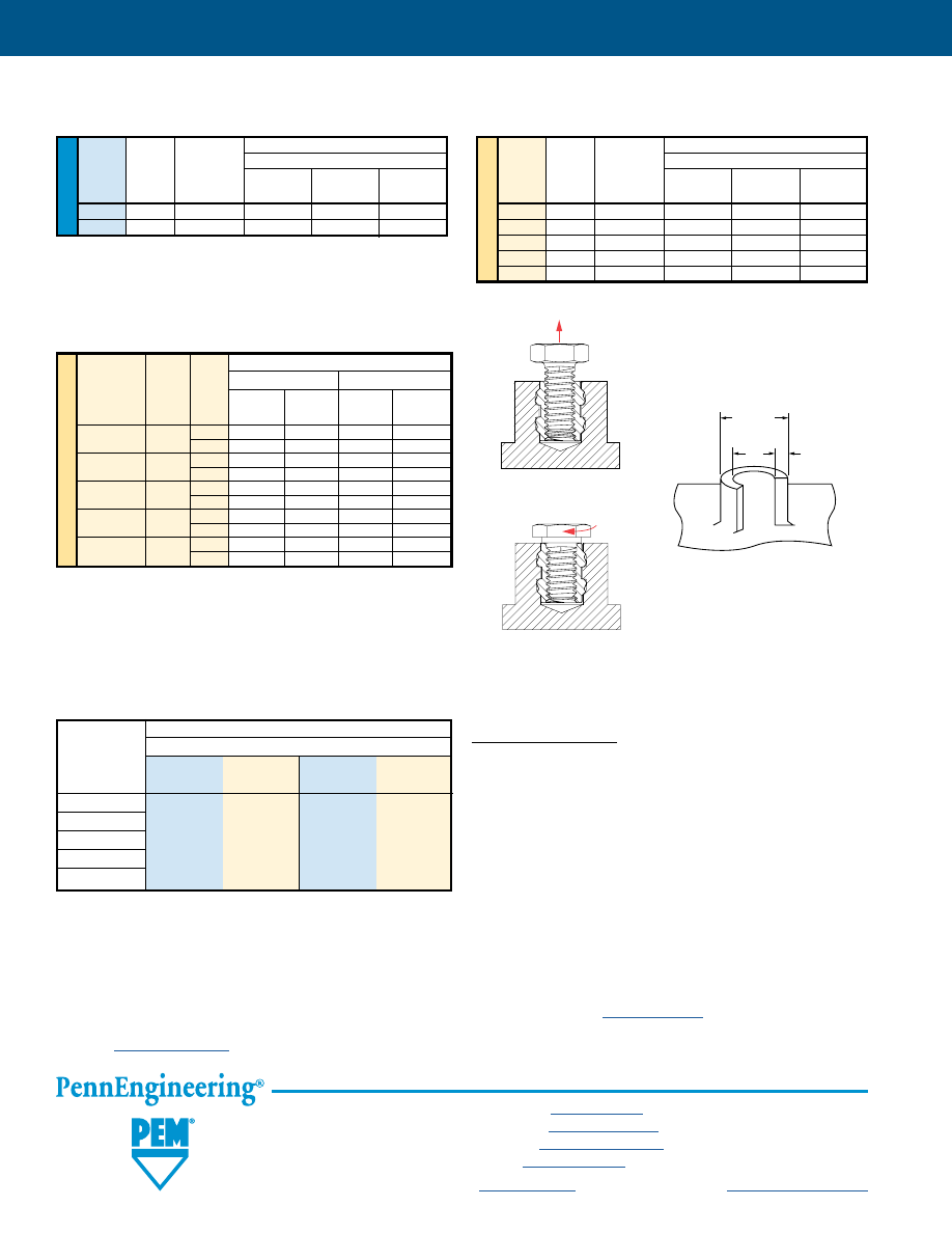
MPF-16
All PEM® products meet our stringent quality standards. If you require additional industry or other specific
quality certifications
, special procedures and/or part
numbers are required. Please contact your local sales office or representative for further information.
Regulatory
compliance information
is available in Technical Support section of our website. Specifications subject to change without notice. See our website for the
most current version of this bulletin.
North America:
Danboro, Pennsylvania USA
•
E-mail:
info@pemnet.com
•
Tel: +1-215-766-8853
•
800-237-4736 (USA)
Europe:
Galway, Ireland
•
E-mail:
europe@pemnet.com
•
Tel: +353-91-751714
Asia/Pacific:
Singapore
•
E-mail:
singapore@pemnet.com
•
Tel: +65-6-745-0660
Shanghai, China
•
E-mail:
china@pemnet.com
•
Tel: +86-21-5868-3688
Visit our PEMNET™ Resource Center at
www.pemnet.com
•
Technical support e-mail:
techsupport@pemnet.com
microPEM® FASTENERS
SMTSO
(2)(3)
FASTENERS
SMTSO TESTING CONDITIONS
Oven
Quad ZCR convection oven with 4 zones
High Temp
518˚F / 270˚C
Board Finish
62% Sn, 38% Pb
Screen Printer
Ragin Manual Printer
Vias
None
Spokes
2 Spoke Pattern
Paste (lead-free)
Amtech NC559LF Sn96.5/3.0Ag/0.5Cu (SAC305)
Stencil
.0067” / 0.17mm thick
Test Sheet Material
Type
.062” Single Layer RF-4
and Size
Pushout Pushout Torque-out Torque-out
(lbs.)
(N)
(in. lbs.)
(N•m)
SMTSO-080
SMTSO-M1
SMTSO-M1.2
85.1
378.7
4.94
0.56
SMTSO-M1.4
SMTSO-M1.6
(1) Torque-out performance will depend on the strength and type of screw being used. In most cases, the screw threads will fail before the insert threads.
(2) With lead-free paste. Average values of 30 test points. The data presented here is for general comparison purposes only. Actual performance is
dependent upon application variables. We will be happy to provide samples for you to install. If required, we can also test your installed hardware and
provide you with the performance data specific to your application.
(3) Further testing details can be found in our web site’s literature section.
ME
TR
IC
Type
Thread Length
Code Code Pullout Torque-out Pullout Torque-out
(N)
(N•cm)
(1)
(N) (N•cm)
(1)
MSIA/MSIB M1 100 50 3.5 50 4.5
250 150 10 200 12
MSIA/MSIB M1.2 100 50 3.5 50 4.5
250 150 10 200 12
MSIA/MSIB M1.4
150 100
15
140
15
300 330 30 400 30
MSIA/MSIB M1.6 150 100 15 140 15
300 330 30 400 30
MSIA/MSIB M2 300 335 35 410 33
400 470 40 595 35
Test Sheet Material
ABS
Polycarbonate
Pullout
is the force required to
pull the insert from the sheet.
Torque-out
is the torque required to turn the insert in the parent
material after installation without inducing clamp load on the fastener.
MSIA/MSIB INSERTS
For testing purposes, inserts were installed using heat stake
equipment into a flat sheet.
HOLE PREPARATION
GUIDELINES
Thinner walls and bosses may be
used but will affect performance.
Wall Thickness.
Boss Dia.
2 x Insert Dia.
Insert
Dia.
PERFORMANCE DATA
MSOFS STANDOFFS
U
NIF
IE
D
Max. Rec.
Test Sheet Material
Thread
Tightening
.008” 300 Series Stainless Steel
Type
Code
Torque For
Mating Screw
Installation
Pushout
Torque-out
(in. lbs.)
(lbs.)
(lbs.)
(in.lbs.)
MSOFS
080 .65 1500 69.8 1.29
MSOFS
256 1.3 1800 91.2 1.29
ME
TR
IC
Max. Rec.
Test Sheet Material
Thread
Tightening
0.2 mm 300 Series Stainless Steel
Type
Code
Torque For
Mating Screw
Installation
Pushout
Torque-out
(N•m)
(kN)
(N)
(N•m)
MSOFS
M1 0.019 6.67 311 0.146
MSOFS
M1.2
0.036
6.67
311
0.146
MSOFS
M1.4
0.057
6.67
311
0.146
MSOFS
M1.6
0.084
8
406
0.146
MSOFS
M2 0.175 8
406 0.146
pem-html.html
PF
™
PEM® CAPTIVE
PANEL SCREWS
PEM® access hardware for enclosures
where the screw must remain with the
door or panel.
Bulletin PF-617
Rev 1217
pem-html.html
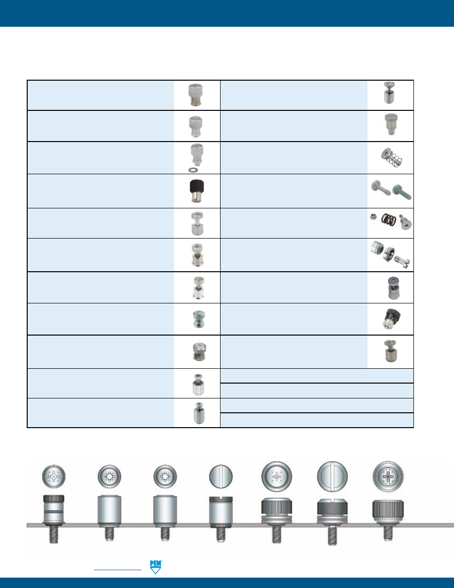
PF-2
PennEngineering •
www.pemnet.com
PEM® brand captive panel screws are designed to help keep parts to a minimum and eliminate risks associated with loose
hardware that could fall out and damage internal components. These panel fastener assemblies are ideal to attach metal
panels or other thin material components in applications where subsequent access will be necessary.
PEM® CAPTIVE PANEL SCREWS
PFC2™/PFS2™ screw head, spring-loaded
captive panel screws -
PAGE 16
PTL2™/PSL2™ locating pin, spring-loaded
plunger assemblies -
PAGE 17
SCBR™ tool only, spinning clinch bolt with
spring -
PAGE 18
SCB™/SCBJ™ tool only, spinning clinch bolts,
no spring -
PAGE 19
HSCB™, HSR™, and HSL™ heat sink mounting
fastener system -
PAGES 20 - 21
PF10™ tool only, flush-mounted captive panel
screws, no spring -
PAGES 22 - 23
REELFAST® SMTPFLSM™ surface mount
spring-loaded captive panel screws -
PAGE 24
REELFAST® SMTPF™ surface mount, panel
screw components and assembly data -
PAGE 25
PFK™ screw head, spring-loaded broaching
captive panel screws -
PAGE 26
Value-added capabilities -
PAGE 27
Captive panel screw installation -
PAGES 28 - 36
Captive panel screw performance data -
PAGES 37 - 41
Captive panel screw capabilities -
PAGE 42
PF11™/PF12™/PF11M™/PF12M™ large knob,
spring-loaded self-clinching panel screws
-
PAGE 5
PF11MF™ large knob, spring-loaded flare-
mounted captive panel screws
-
PAGE 6
PF11MW™ large knob, spring-loaded flare-
mounted, floating captive panel screws
-
PAGE 7
PF11PM™ large knob, spring-loaded plastic
PEM® C.A.P.S.® captive panel screws -
PAGE 8
PFHV™ screw head, no spring captive panel
screws -
PAGE 9
PF7M™ screw head, spring-loaded self-
clinching captive panel screws -
PAGE 10
PF7MF™ flare-mounted captive panel screws
for installing into stainless steel -
PAGE 11
PF30™ low-profile knob, spring-loaded captive
panel screws -
PAGE 12
PF50™ and PF60™ low-profile knob, spring-
loaded captive panel screws -
PAGE 13
PFC4™ recessed-head captive panel screws
for installing into stainless steel -
PAGE 14
PFC2P™ tool only, non flush, spring-loaded
captive panel screws -
PAGE 15
HEIGHT COMPARISON GUIDE AND STANDARD DRIVER RECESS
PFC4
PF11/PF12
PF11M/PF12M
PFC2/PFS2
PFK
PFC2P
PF50/PF51/PF52
PF60/PF61/PF62
PF30/31/32
PF7M/PF7MF
Installed and fastened height above sheet for M3 Thread size.
pem-html.html
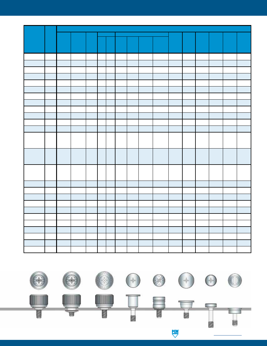
PennEngineering •
www.pemnet.com
PF-3
PF11
5
• • •
•
•
PF11M
5
•
•
•
• • •
PF12
5
• •
•
•
PF12M
5
•
•
• • •
PF11MF
6
•
•
•
• • • • • •
PF12MF
6
•
•
• • • • • •
PF11MW
7
•
•
•
•
• • • • • • •
PF12MW
7
•
•
•
• • • • • • •
PEM C.A.P.S. 8
• • •
•
•
(1)
• •
PFHV
9
•
•
•
PF7M 10
• • •
•
•
PF7MF 11
• • • •
•
•
•
•
PF30
PF31 12
• • •
•
PF32
PF50
PF51 13
• • •
•
•
PF52
PF60
PF61 13
• •
•
•
PF62
PFC4 14
• •
•
• •
PFC2P 15
•
• •
•
•
PFC2 16
•
• • •
•
•
PFS2 16
• • •
•
•
SCBR 18
• •
SCB/SCBJ 19
•
•
HSCB 20-21
• •
PF10 22-23
•
•
•
•
SMTPFLSM 24
• • • •
•
•
SMTPF 25
• • •
•
•
(1)
•
PFK 26
•
• • • •
•
•
(1) Standard color is black.
CAPTIVE PANEL SCREW SELECTOR GUIDE
A p p l i c a t i o n R e q u i r e s :
PEM®
Panel
Fastener Page
Type No.
Actuation
Installs into
Includes
Painted
Available anti Mating
High
Printed Stainless panels Multiple Flush Available
in
cross-
hole
UL
corrosion Spring Tool Hand Thinner circuit
steel
and/or any
screw mounted
in
custom threading
misa-
Approved resistance loaded
sheets boards
sheet
hardness
lengths top side
black
colors
feature lignment
PF11MF
PF11MW
PFHV
SCB/SCBJ
PF10
PEM C.A.P.S.®
SCBR
HSCB
pem-html.html
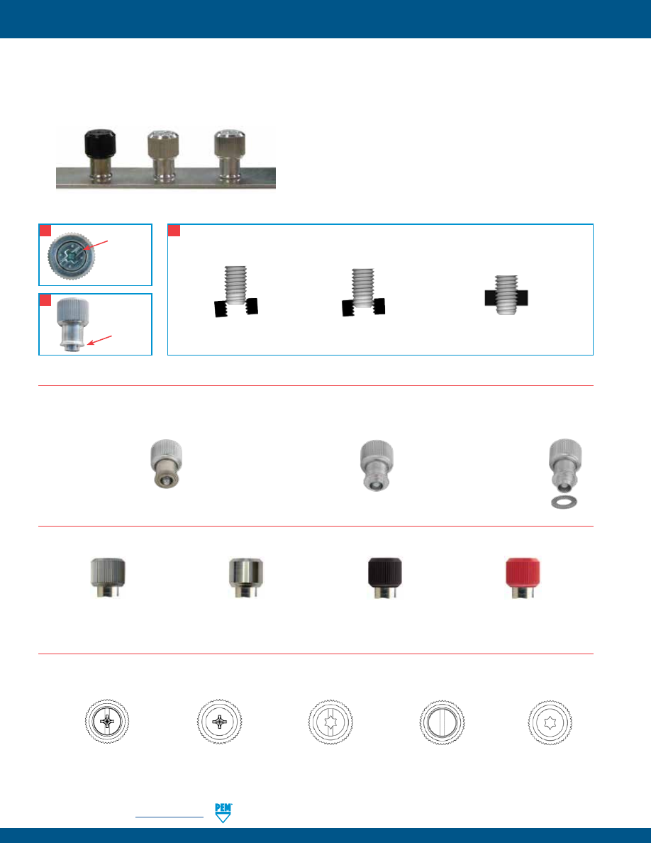
PF-4
PennEngineering •
www.pemnet.com
PEM® PF11™/PF12™ CAPTIVE PANEL SCREWS
PEM® PF11/PF12 panel fasteners provide design flexibility by offering three styles of installation types, each having the same profile
or look above the sheet or panel into which it is installed. The various mounting types include self-clinching, flare-mounted, and
floating styles. Each offers a distinct advantage depending on your application. The standard selection of knobs include knurled
or smooth metal caps and plastic PEM C.A.P.S.® (colored access panel screws).
•
Installs flush on back side of panel.
•
Available in three screw
lengths.
Self-clinching
Flare-mounted, Floating
•
Compensates for mating hole misalignment.
•
Installs into any panel hardness.
Key features include:
1)
Universal Phillips/slot drive (except for plastic cap).
2)
Shoulder on retainer to provide positive stop during installation.
3)
Anti cross-threading feature (designated with an “M” in the
part number). Eases assembly, aligns components, improves
assembly line productivity, prevents jamming, and slides
through clogged internal threads.
Self-clinching Flare-mounted
Floating
Black Metal Cap
DuraBlack™ finish is scratch resistant.
Finish is on both metal cap and screw.
(finish code “BL”)
Metal Cap Un-knurled
All metal cap available
without knurls.
Plastic Cap
Available with custom
color plastic cap.
(See page 8 for colors)
-1-
MISALIGNED AXIS
-2-
THREADS CAM
-3-
THREADS DRIVE NORMALLY
ANTI CROSS-THREAD TECHNOLOGY - HOW IT WORKS
PennEngineering is a licensee for MAThread® technology, a registered trademark of MAThread Inc.
3
Universal
Phillips/
slot
drive*
1
2
Shoulder
on
retainer
Available Drive Configurations:
PF11
P
Phillips
(Optional)
PF11
LS
Torx®/Slot
Combination
(Optional)
PF11
L
Torx®
(Optional)
PF11
S
Slotted
(Optional)
Standard Mounting Styles:
Standard Cap Selection:
Metal Cap knurled
All metal cap available with
knurls.
•
Appropriate for close centerline-to-edge
applications.
•
Doesn’t require high installation
force.
•
Installs into any panel hardness.
•
Installs flush on back side of panel.
•
Can be installed into most any thin
material.
•
Appropriate for painted panels.
Flare-mounted
* Plastic cap version has Phillips drive only.
PF11
Phillips/slot
(Standard -
except for plastic cap)
PennEngineering is a licensee for Acument Global Technologies (Torx®).
© 2017 PennEngineering.
pem-html.html
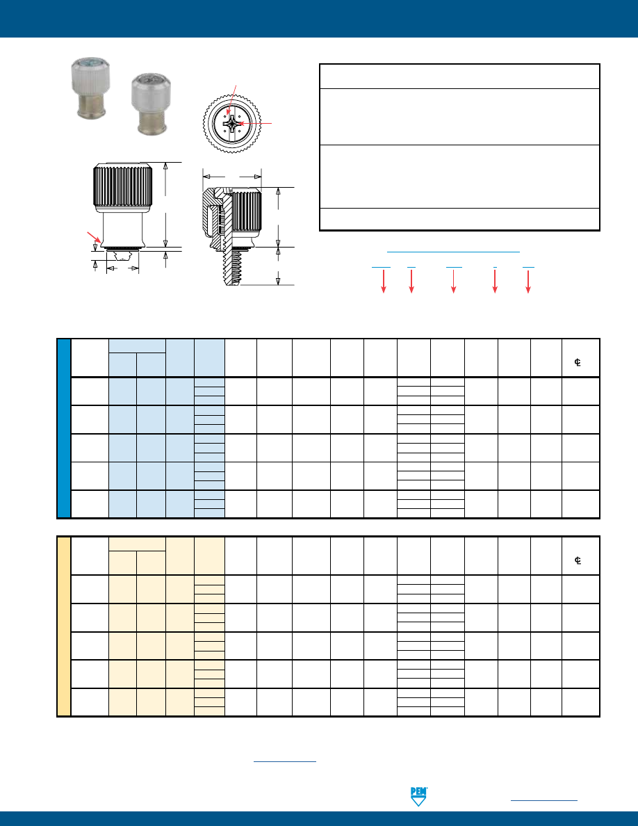
PennEngineering •
www.pemnet.com
PF-5
ME
TR
IC
U
NIF
IE
D
Type
Screw
Hole Size
Min. Dist.
Thread
Thread Length A
Min.
In Sheet
C
E
G
P
T
1
T
2
Driver Hole
Size
Knurled Smooth Code Code Max.
Sheet
+ .003
Max.
± .010
± .025
± .025
Nom.
Nom.
Size
C/L
To
Cap Cap
Thickness
-
.000 Edge
.112-40 PF11 PF12 0
.170 .000
(#4-40) PF11M PF12M 440 1 .036 .036 .219 .218 .417 .230 .060 .310 .450 #1 .28
2
.290 .120
.138-32 PF11 PF12 0
.230 .000
(#6-32)
PF11M PF12M 632 1
.036 .036
.250 .249 .450 .290 .060 .450 .640 #2
.29
2
.350 .120
.164-32
PF11 PF12 0
.230 .000
(#8-32)
PF11M PF12M 832 1
.036 .036
.312
.311 .514 .290 .060 .450 .640 #2
.33
2
.350 .120
.190-32
PF11 PF12 0
.230 .000
(#10-32) PF11M PF12M 032 1 .036 .036 .312 .311 .514 .290 .060 .450 .640 #2 .33
2
.350 .120
.250-20 PF11 PF12 0
.290 .000
(1/4-20) PF11M PF12M 0420 1 .036 .036 .375 .374 .575 .350 .060 .530 .790 #3 .46
2
.410 .120
All dimensions are in inches.
All dimensions are in millimeters.
Type
Screw Hole Size
Min.
Dist.
Thread
Thread Length A
Min.
In Sheet
C E G P T
1
T
2
Driver Hole
Size x
Knurled Smooth Code Code Max.
Sheet
+ 0.08
Max.
± 0.25
± 0.64
± 0.64
Nom.
Nom.
Size
C/L
To
Pitch
Cap Cap
Thickness
Edge
PF11 PF12 0
4.32 0
M3 x 0.5
PF11M PF12M M3 1 0.92 0.92
5.56 5.54 10.59 5.84 1.52 7.87 11.43 #1
7.11
2 7.37 3.05
PF11 PF12 0
5.84 0
M3.5 x 0.6 PF11M PF12M
M3.5 1 0.92 0.92 6.35 6.33 11.43 7.37 1.52 11.43 16.26 #2 7.37
2 8.89
3.05
PF11 PF12 0
5.84 0
M4 x 0.7
PF11M PF12M M4 1 0.92 0.92
7.92
7.9 13.06 7.37 1.52 11.43 16.26 #2
8.38
2 8.89
3.05
PF11 PF12 0
5.84 0
M5 x 0.8
PF11M PF12M M5 1 0.92 0.92
7.92
7.9 13.06 7.37 1.52 11.43 16.26 #2
8.38
2 8.89
3.05
PF11 PF12 0
7.37 0
M6 x 1
PF11M PF12M M6 1 0.92 0.92
9.53
9.5 14.61 8.89 1.52 13.46 20.07 #3
11.68
2 10.41
3.05
PEM® PF11™/PF12™/PF11M™/PF12M™ CAPTIVE PANEL SCREWS
Installation Data page 28. Performance Data page 36.
PF11
Knurled Cap
PF12
Smooth Cap
(1) As with all Class 2A/6g external threads with an additive finish, the maximum major and pitch, after plating, may equal basic sizes and be gauged to
Class 3A/4h, per ANSI B1.1, Section 8, Table 3A and ANSI B1.13M, Section 8, Paragraph 8.2.
(2) “BL” suffix will be added to part number to designate DuraBlack™ finish.
(3) See PEM Technical Support section of our website (
www.pemnet.com
) for related plating standards and specifications.
PF11
M –
632 – 1
BL
PART NUMBER DESIGNATION
Type Optional
Anti-cross thread
feature
Thread
Code
Screw
Length
Code
Optional
DuraBlack
finish
Threads:
External, ASME B1.1, 2A / ASME B1.13M, 6g
Material:
Knob: Aluminum
Retainer: Hardened Carbon Steel
Screw (PF11/PF12): 400 Series Stainless Steel
Screw (PF11M/PF12M): Hardened Carbon Steel
(1)
Spring: 300 Series Stainless Steel
Finish: Optional Finish (BL):
Knob: Natural Finish
Knob: Black anodize
(2)
Retainer: Bright nickel over copper flash
Screw: Black nitride,
per ASTM B689
AMS2753, Section 3
(2)
Screw (PF11/PF12): Passivated and/or tested per ASTM A380
Screw: (PF11M/PF12M): Zinc plated, 5µm, colorless
(3)
Spring: Natural Finish
For use in sheet hardness:
HRB 80 or less (Hardness Rockwell “B” Scale) / HB 150 or less (Hardness Brinell)
Float .010”/0.25mm minimum, in all directions from center, .020”/0.5mm total.
G
E
A
C
T
2
T
1
Dimples on head
designate metric thread.
P
Phillips
driver size.
(See chart)
Shoulder
provides
positive
stop during
installation.
Clinching profile may vary.
pem-html.html
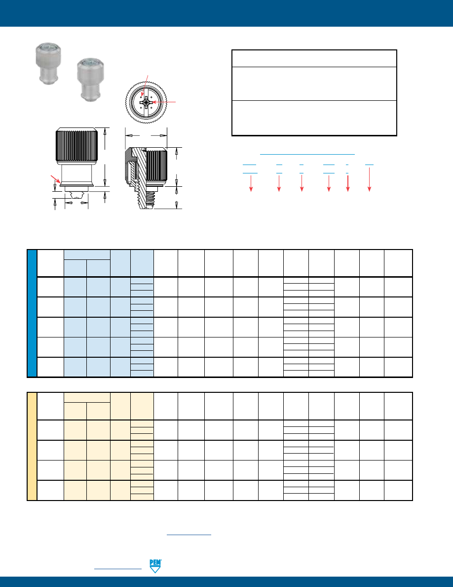
PF-6
PennEngineering •
www.pemnet.com
ME
TR
IC
U
NIF
IE
D
PEM® PF11MF™ FLARE-MOUNTED CAPTIVE PANEL SCREWS
Type
Screw
Hole Size
Thread
Thread Length A
Min.
In Sheet
C
E
G
P
T
1
T
2
Driver
Size Knurled Smooth Code Code Max.
Sheet
+ .005
Max.
± .010
± .025
± .025
Nom.
Nom.
Size
Cap Cap
Thickness
- .000
.112-40 0
.170 .000
(#4-40)
PF11MF PF12MF 440 1
.041
.031
.187
.186 .417 .230 .055 .310 .450
#1
2 .290
.115
.138-32 0
.230 .000
(#6-32)
PF11MF PF12MF 632 1
.072 .060
.213
.212 .450 .290 .024 .450 .640
#2
2 .350
.084
.164-32
0 .230
.000
(#8-32)
PF11MF PF12MF 832 1
.072 .060
.266 .265 .514 .290 .024 .450 .640
#2
2 .350
.084
.190-32
0 .230
.000
(#10-32) PF11MF PF12MF 032 1 .072 .060 .266 .265 .514 .290 .024 .450 .640 #2
2 .350
.084
.250-20 0
.290 .000
(1/4-20)
PF11MF PF12MF 0420 1
.072
.060
.323
.322
.575 .350 .024
.530 .790
#3
2 .410
.084
Type
Screw Hole Size
Thread
Thread Length A
Min.
In Sheet C E G P T
1
T
2
Driver
Size x
Knurled Smooth Code
Code Max.
Sheet
+ 0.1
Max.
± 0.25
± 0.64
± 0.64
Nom.
Nom.
Size
Pitch
Cap
Cap
Thickness
0 4.32
0
M3 x 0.5
PF11MF PF12MF M3 1
1.05 0.79
4.75 4.73 10.59 5.84 1.4
7.87 11.43
#1
2 7.37
2.92
0 5.84
0
M4 x 0.7
PF11MF PF12MF M4 1
1.83 1.52
6.76 6.74 13.06 7.37 0.61 11.43 16.26 #2
2 8.89
2.13
0 5.84
0
M5 x 0.8
PF11MF PF12MF M5 1
1.83 1.52
6.76 6.74 13.06 7.37 0.61 11.43 16.26 #2
2 8.89
2.13
0 7.37
0
M6 x 1
PF11MF PF12MF M6 1
1.83 1.52
8.2
8.18 14.61 8.89 0.61 13.46 20.07 #3
2 10.41
2.13
All dimensions are in inches.
All dimensions are in millimeters.
PF11MF
Knurled Cap
PF12MF
Smooth Cap
(1) As with all Class 2A/6g external threads with an additive finish, the maximum major and pitch, after plating, may equal basic sizes and be gauged to
Class 3A/4h, per ANSI B1.1, Section 8, Table 3A and ANSI B1.13M, Section 8, Paragraph 8.2.
(2) “BL” suffix will be added to part number to designate DuraBlack™ finish.
(3) See PEM Technical Support section of our website (
www.pemnet.com
) for related plating standards and specifications.
PF11
M
F – 632 – 1
BL
PF12
M
F – 632 – 1
PART NUMBER DESIGNATION
Type
Anti-cross
Thread
Feature
Thread
Code
Screw
Length
Code
Optional
DuraBlack
finish
Flare-
mounted
Style
Threads:
External, ASME B1.1, 2A / ASME B1.13M, 6g
(1)
Material:
Knob: Aluminum
Retainer: Aluminum
Screw: Hardened Carbon Steel
Spring: 300 Series Stainless Steel
Finish:
Optional Finish (BL):
Knob: Natural Finish
Knob: Black anodize
(2)
Retainer: Natural Finish
Screw: Black nitride
Screw: Zinc plated, 5µm, colorless
(3)
AMS2753,
Spring: Natural Finish
Section 3
(2)
Installation Data page 28. Performance Data page 36.
Float .010”/0.25mm minimum, in all directions from center, .020”/0.5mm total.
C
A
T
2
G
T
1
E
P
Dimples on head
designate metric thread.
Phillips
driver size.
(See chart)
Shoulder
provides
positive
stop during
installation.
pem-html.html
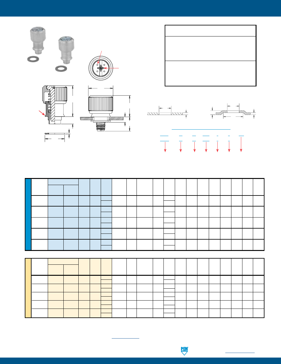
PennEngineering •
www.pemnet.com
PF-7
ME
TR
IC
U
NIF
IE
D
PEM® PF11MW™ FLARE-MOUNTED, FLOATING CAPTIVE PANEL SCREW
Type
Screw
A
D
Hole
Size
Thread
Thread Shank Length
Max.
B
In Sheet
E
G
H
L
1
L
2
T
1
T
2
Driver Min. W
Size
Knurled Smooth Code Code Code Sheet Min. +.003 ±.010 Nom. Min. Nom. Max. Nom. Nom. Size Total Nom.
Cap Cap (4)
(4)
Thickness
–.001
Float
.112-40
1
.230
(#4-40) PF11MW PF12MW 440 1 2 .063 .111 .250 .417 .290 .375 .137 .127 .310 .450 #1 .073 .312
.138-32
1
.290
(#6-32) PF11MW PF12MW 632 1 2 .063 .115 .283 .450 .350 .413 .149 .127 .450 .640 #2 .076 .344
.164-32
1
.290
(#8-32) PF11MW PF12MW 832 1 2 .063 .121 .346 .514 .350 .469 .157 .140 .450 .640 #2 .076 .407
.190-32
1
.290
(#10-32) PF11MW PF12MW 032 1 2 .063 .121 .346 .514 .350 .469 .157 .140 .450 .640 #2 .076 .407
.250-20
1
.350
(1/4-20) PF11MW PF12MW 0420 1
2
.063 .128 .413 .575
.410
.531 .157 .140 .530 .790 #3 .081 .468
Type
Screw
A
D
Hole
Size
Thread
Thread Shank Length
Max.
B
In Sheet
E
G
H
L
1
L
2
T
1
T
2
Driver Min. W
Size x
Knurled Smooth Code Code Code Sheet Min. +0.08 ±0.25 Nom. Min. Nom. Max. Nom. Nom. Size Total Nom.
Pitch Cap Cap (4)
(4)
Thickness
–0.03
Float
M3 x 0.5
PF11MW
PF12MW
M3
1
1 1.6 2.82 6.35 10.59 5.84 9.52 3.48 3.23 7.87 11.43 #1 1.85 7.92
2
7.37
M3.5 x 0.6
PF11MW
PF12MW
M3.5
1
1 1.6 2.92 7.19 11.43 7.37 10.49 3.78 3.23 11.43 16.26 #2 1.93 8.74
2
8.89
M4 x 0.7
PF11MW
PF12MW
M4
1
1 1.6 3.07 8.79 13.06 7.37 11.91 3.99 3.56 11.43 16.26 #2 1.93 10.34
2
8.89
M5 x 0.8
PF11MW
PF12MW
M5
1
1
1.6 3.07 8.79 13.06
7.37 11.91 3.99 3.56 11.43 16.26 #2 1.93 10.34
2
8.89
M6 x 1
PF11MW
PF12MW
M6
1
1
1.6 3.25 10.49 14.61 8.89 13.48 3.99 3.56 13.46 20.07 #3 2.06 11.89
2
10.41
All dimensions are in inches.
All dimensions are in millimeters.
PF11MW panel fasteners are shipped with mating washers.
PF11MW
Knurled Cap
PF12MW
Smooth Cap
(1) As with all Class 2A/6g external threads with an additive finish, the maximum major and pitch, after plating, may equal basic sizes and be gauged to
Class 3A/4h, per ANSI B1.1, Section 8, Table 3A and ANSI B1.13M, Section 8, Paragraph 8.2.
(2) “BL” suffix will be added to part number to designate DuraBlack™ finish.
(3) See PEM Technical Support section of our website (
www.pemnet.com
) for related plating standards and specifications.
(4) Other shank and screw lengths available.
PF11
M
W – 632 – 1
1
BL
PF12
M
W – 632 – 1
1
PART NUMBER DESIGNATION
Type
Thread
Code
Shank
Code
(4)
Screw
Length
Code
(4)
Anti-
cross
Thread Feature
Optional
DuraBlack
finish
Floating
style
Threads:
External, ASME B1.1, 2A / ASME B1.13M, 6g
(1)
Material:
Knob: Aluminum
Retainer: Aluminum
Screw: Hardened Carbon Steel
Spring: 300 Series Stainless Steel
Washer: 300 Series Stainless Steel
Finish:
Optional Finish (BL):
Knob: Natural Finish
Knob: Black anodize
(2)
Retainer: Natural Finish
Screw: Black nitride,
Screw: Zinc plated, 5µm, colorless
(3)
AMS2753,
Spring: Natural Finish
Section 3
(2)
Washer: Natural Finish
PANEL CONFIGURATION 2
For applications where a space between
mating panels is not acceptable.
D
H
A
B
PANEL CONFIGURATION 1
For applications where a space
between mating panels is acceptable.
D
A
Installation Data page 29. Performance Data page 36.
L
1
.025” / 0.64mm Nom.
T
2
G
T
1
E
W
Dimples on head
designate metric thread.
Phillips
driver size.
(See chart)
Shoulder
provides
positive
stop during
installation.
L
2
pem-html.html

PF-8
PennEngineering •
www.pemnet.com
ME
TR
IC
U
NIF
IE
D
Type
Screw A
Hole Size
Min. Dist.
Thread
Thread Length (Shank)
Min.
In Sheet
C
E
G
P
T
1
T
2
Driver Hole
Size
Knurled
Code
Code Max.
Sheet
+ .003
Max.
± .010
± .025
± .025
Nom.
Nom.
Size
C/L
To
Cap
Thickness
-
.000
Edge
.112-40
0
.170
.000
(#4-40) PF11PM 440 1 .036 .036 .219 .218 .417 .230 .060 .310 .450 #2 .28
2
.290
.120
.138-32 0 .230
.000
(#6-32) PF11PM 632 1 .036 .036 .250 .249 .450 .290 .060 .450 .640 #2 .29
2
.350
.120
.164-32
0
.230
.000
(#8-32) PF11PM 832 1 .036 .036 .312 .311 .514 .290 .060 .450 .640 #2 .33
2
.350
.120
.190-32
0
.230
.000
(#10-32) PF11PM 032 1 .036 .036 .312 .311 .514 .290 .060 .450 .640 #2 .33
2
.350
.120
All dimensions are in inches.
All dimensions are in millimeters.
Thread Type Screw A Hole Size
Min.
Dist.
Size x Thread
Length (Shank)
Min.
In Sheet C E G P T
1
T
2
Driver Hole
Pitch
Knurled
Code
Code Max.
Sheet
+ 0.08
Max.
± 0.25
± 0.64
± 0.64
Nom.
Nom.
Size
C/L
To
Cap
Thickness
Edge
0
4.32
0
M3 x 0.5
PF11PM
M3
1
0.92
0.92
5.56
5.54
10.59
5.84
1.52
7.87
11.43
#2
7.11
2
7.37
3.05
0
5.84
0
M4 x 0.7
PF11PM
M4
1
0.92
0.92
7.92
7.9
13.06
7.37
1.52
11.43
16.26
#2
8.38
2
8.89
3.05
0
5.84
0
M5 x 0.8
PF11PM
M5
1
0.92
0.92
7.92
7.9
13.06
7.37
1.52
11.43
16.26
#2
8.38
2
8.89
3.05
(1) The colors shown (except for black) are non-stocked standards and available on special order. Since actual color knob may vary slightly from those
represented, we recommend that you request samples for color verification. If you require a custom color or you need a “color matched” knob, please
contact us.
(2) As with all Class 2A/6g external threads with an additive finish, the maximum major and pitch, after plating, may equal basic sizes and be gauged to
Class 3A/4h, per ANSI B1.1, Section 8, Table 3A and ANSI B1.13M, Section 8, Paragraph 8.2.
(3) Temperature limit is 210˚ F / 99˚ C.
(4) See PEM Technical Support section of our website (
www.pemnet.com
) for related plating standards and specifications.
Also available with
flare-mounted
retainer as PF11PMF
or with floating style
retainer as PF11PMW.
Threads:
External, ASME B1.1, 2A /
ASME B1.13M, 6g
(2)
Material:
Knob: PC/ABS (UL 94V-0, halogen-free)
(3)
Retainer: Hardened Carbon Steel
Screw: Hardened Carbon Steel
Spring: 300 Series Stainless Steel
Finish
:
Retainer: CN - Bright nickel over
copper flash per ASTM B689
Screw: Zinc plated, 5µm, colorless
(4)
Spring: Natural Finish
For use in sheet hardness:
HRB 80 or less (Hardness Rockwell “B” Scale)
HB 150 or less (Hardness Brinell)
PEM® C.A.P.S.® CAPTIVE PANEL SCREWS
Installation Data page 28. Performance Data page 37.
Black = B
(Standard)
Patented.
PF11
P
M – 632 – 0
B
PART NUMBER DESIGNATION
Type
Thread
Code
Screw
Length
Code
Color
Code
(Standard
Black)
Phillips
Drive
Anti-
cross
Thread
Feature
Red = R
Orange = N
Yellow = Y
Green = G
Blue = U
Violet = V
Metallic = M
Color Capabilities
(1)
Choose a knob color code and add it to the end of the base part number.
Float .010”/0.25mm minimum, in all directions from center, .020”/0.5mm total.
G
E
A
C
T
2
T
1
P
PEM® C.A.P.S.® dot
pattern (Registered
trademark)
Dimples on head
designate metric thread.
Phillips
driver size.
(See chart)
Shoulder
provides
positive
stop during
installation.
Clinching profile may vary.
pem-html.html
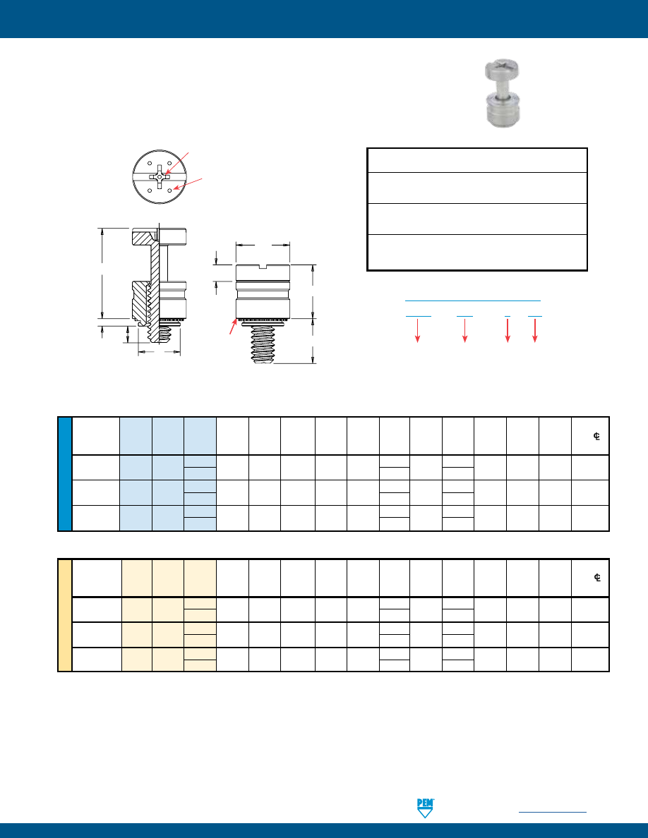
PennEngineering •
www.pemnet.com
PF-9
PEM® PFHV™ CAPTIVE PANEL SCREWS
ME
TR
IC
U
NIF
IE
D
Screw A
Min.
Hole
Size
Min. Dist.
Thread
Type Thread Length (Shank)
Sheet
In Sheet
C
E
G
H
P
T
1
T
2
Driver
Hole
C/L
Size
Code Code Max. Thickness + .003
Max.
± .010
± .025
± .005
±.025
Nom.
Nom. Size To Edge
-
.000
.112-40
PFHV 440
0
.036 .036 .203 .202 .260
.216
.080
.000
.260 .436 #1 .21
(#4-40) 1 .316
.095
.138-32
PFHV 632
0
.036 .036 .219 .218 .276
.234
.092
.000
.290 .484 #2 .23
(#6-32) 1
.359
.120
.164-32
PFHV 832
0
.036 .036 .252 .251 .309
.259
.111
.000
.335 .555 #2 .26
(#8-32) 1 .371
.106
All dimensions are in inches.
All dimensions are in millimeters.
Thread
Screw A
Min.
Hole Size
Min. Dist.
Size x
Type Thread Length (Shank)
Sheet
In Sheet C E G H P
T
1
T
2
Driver
Hole
C/L
Pitch Code
Code Max.
Thickness
+ 0.08
Max.
± 0.25
± 0.64
± 0.13
±0.64
Nom.
Nom. Size To Edge
M3 x 0.5
PFHV
M3
0
0.92 0.92 5.5 5.49 6.95
5.55
2.03
0
6.69 11.25 #1 5.8
1 7.56 1.9
M3.5 x 0.6
PFHV
M3.5
0
0.92 0.92 6 5.98 7.45
6.01
2.34
0
7.45 12.47 #2 6.3
1 8.42 2.3
M4 x 0.7
PFHV
M4
0
0.92 0.92 6.4 6.38 7.85
6.59
2.79
0
8.5 14.1 #2 6.7
1
9.39 2.7
PFHV – 632 – 0
CN
PART NUMBER DESIGNATION
Type
Thread Size
Code
Screw
Length
Code
Finish
Code
(1) As with all Class 2A/6g external threads with an additive finish, the maximum major and pitch, after plating, may equal basic sizes and be gauged to
Class 3A/4h, per ANSI B1.1, Section 8, Table 3A and ANSI B1.13M, Section 8, Paragraph 8.2.
Threads:
External, ASME B1.1, 2A / ASME B1.13M, 6g
(1)
Material:
Retainer: Carbon Steel
Screw: Hardened Carbon Steel
Finish
:
Retainer: CN - Bright nickel over copper flash per ASTM B689
Screw: CN - Bright nickel over copper flash per ASTM B689
(1)
For use in sheet hardness:
HRB 60 or less (Hardness Rockwell “B” Scale)
HB 107 or less (Hardness Brinell)
•
Low cost captive screw design to replace loose hardware.
•
Small, compact and low profile design for limited access areas.
•
Two screw lengths.
•
Universal slot/Phillips recess standard.
•
Available with MAThread® anti cross-thread technology. (See page 4 for more information).
•
Available with Torx® recess.
Installation Data page 29. Performance Data page 37.
G
H
E
P
C
A
T
1
T
2
Dimples on head
designate metric
thread.
Phillips
driver size.
(See chart)
For available drive
configurations, see page 4.
Shoulder
provides
positive
stop during
installation.
Clinching profile may vary.
pem-html.html
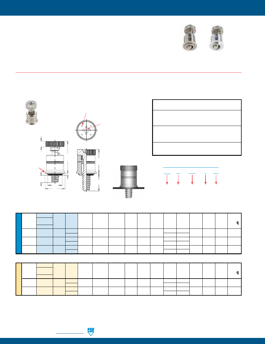
PF-10
PennEngineering •
www.pemnet.com
•
Smallest footprint, spring-loaded panel fastener for limited access areas.
•
MAThread® anti cross-thread technology. (See page 4 for more information).
•
Installs flush on back side of panel.
•
PF7M Self-clinching mounting design provides high pushout resistance.
•
PF7M does not require special hole preparation.
•
PF7MF is appropriate for close centerline-to-edge applications.
•
PF7MF does not require high installation force.
•
PF7MF installs into any panel hardness.
•
Available with Torx® recess.
PEM® PF7M™/PF7MF™ CAPTIVE PANEL SCREWS
U
NIF
IE
D
Type Hole
Size
Min.
Fastener Screw
A Min.
In
Sheet
Dist.
Thread
Material
Thread Length (Shank) Sheet +.003
C
E
H
G
P
T
1
T
2
Driver Hole
C/L
Size
Steel
Code Code Max. Thickness –.000 Max. ±.010 ±.010 ±.025 ±.025 Nom. Nom. Size To
Edge
.112-40 PF7M 440 0 .036 .036 .219 .218 .310 .100 .210 .000 .380 .550 #2 .28
(#4-40)
1 .270 .065
.138-32 PF7M 632 0 .036 .036 .250 .249 .342 .100 .240 .000 .410 .610 #2 .29
(#6-32)
1
.300 .065
.164-32 PF7M 832 0 .036 .036 .312 .311 .405 .120 .240 .000 .430 .630 #2 .33
(#8-32)
1
.300 .065
ME
TR
IC
Type
Min.
Thread Fastener Screw
A Min.
Hole
Size
Dist.
Size x
Material
Thread Length (Shank)
Sheet
In Sheet
C
E
H
G
P
T
1
T
2
Driver Hole
C/L
Pitch
Steel
Code Code Max. Thickness +0.08 Max. ±0.25 ±0.25 ±0.64 ±0.64 Nom. Nom. Size To
Edge
M3 x 0.5
PF
7M M3 0 0.92 0.92 5.56 5.54 7.87 2.5 5.33 0 9.65 13.97 #2 7.11
1 6.86 1.65
M4 x 0.7
PF
7M M4
0
0.92 0.92 7.92 7.9 10.29 3
6.1 0
10.92 16 #2 8.38
1
7.62 1.65
(1) As with all Class 2A/6g external threads with an additive finish, the maximum major and pitch, after plating, may equal basic sizes and be gauged to
Class 3A/4h, per ANSI B1.1, Section 8, Table 3A and ANSI B1.13M, Section 8, Paragraph 8.2.
All dimensions are in inches.
All dimensions are in millimeters.
Patented.
PF
7
M – 632 – 0
CN
PART NUMBER DESIGNATION
Type
Anti
Cross-thread
Feature
Thread
Size
Code
Length
Code
Finish
Threads:
External, ASME B1.1, 2A / ASME B1.13M, 6g
(1)
Material:
Retainer: Carbon Steel
Screw: Hardened Carbon Steel
Spring: 300 Series Stainless Steel
Finish:
Retainer: CN - Bright nickel over copper flash per ASTM B689
Screw: CN - Bright nickel over copper flash per ASTM B689
Spring: Natural Finish
For use in sheet hardness:
HRB 60 or less (Hardness Rockwell “B” Scale)
HB 107 or less (Hardness Brinell)
PF7M™ SELF-CLINCHING CAPTIVE PANEL SCREWS
PF7MF
PF7M
Installation Data page 30. Performance Data page 37.
H
E
T
1
T
2
G
A
C
P
Dimples on head
designate metric thread.
Phillips
driver size.
(See chart)
Shoulder
provides
positive
stop during
installation.
Clinching profile may vary.
pem-html.html
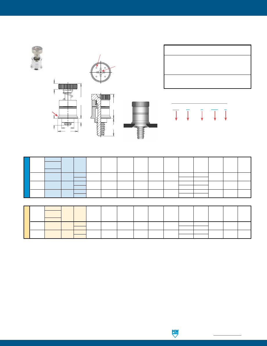
PennEngineering •
www.pemnet.com
PF-11
PEM® PF7M™/PF7MF™ CAPTIVE PANEL SCREWS
U
NIF
IE
D
Type
Hole Size
Fastener Screw
A
Min.
In Sheet
Thread
Material
Thread Length (Shank) Sheet +.005
C
E
H
G
1
G
2
T
1
T
2
Driver
Size
Steel
Code Code Max. Thickness –.000 Max. ±.010 ±.010 ±.025 ±.025 Nom. Nom. Size
.112-40 PF7MF 440 0 .041 .031 .187 .186 .310 .100 .040 .210 .380 .550 #2
(#4-40)
1 .100 .270
.138-32 PF7MF 632 0 .072 .060 .213 .212 .342 .100 .040 .240 .410 .610 #2
(#6-32)
1 .100
.300
.164-32 PF7MF 832 0 .072 .060 .266 .265 .405 .120 .040 .240 .430 .630 #2
(#8-32)
1 .100
.300
ME
TR
IC
Type
Thread Fastener Screw
A
Min.
Hole Size
Size x
Material
Thread Length (Shank)
Sheet
In Sheet
C
E
H
G
1
G
2
T
1
T
2
Driver
Pitch
Steel
Code Code Max. Thickness +0.13 Max. ±0.25 ±0.25 ±0.64 ±0.64 Nom. Nom. Size
M3 x 0.5
PF7MF M3 0 1.05 0.79 4.75 4.73 7.87 2.5 1.02 5.33 9.65 13.97 #2
1 2.54 6.86
M4 x 0.7
PF7MF M4
0
1.83 1.52 6.76 6.74 10.29 3
1.02 6.1
10.92 16 #2
1 2.54
7.62
(1) As with all Class 2A/6g external threads with an additive finish, the maximum major and pitch, after plating, may equal basic sizes and be gauged to
Class 3A/4h, per ANSI B1.1, Section 8, Table 3A and ANSI B1.13M, Section 8, Paragraph 8.2.
All dimensions are in inches.
All dimensions are in millimeters.
Patented.
PF
7
M
F – 632 – 0
PART NUMBER DESIGNATION
Type
Anti
Cross-thread
Feature
Flaring Thread
Size
Code
Length
Code
Threads:
External, ASME B1.1, 2A / ASME B1.13M, 6g
(1)
Material:
Retainer: Aluminum
Screw: Hardened Carbon Steel
Spring: 300 Series Stainless Steel
Spring: Natural Finish
Finish:
Retainer: Natural finish
Screw: CN - Bright nickel over copper flash per ASTM B689
PF7MF™ FLARE-MOUNTED CAPTIVE PANEL SCREWS
Installation Data page 30. Performance Data page 37.
Dimples on head
designate metric thread.
H
E
T
1
T
2
A
C
G
2
G
1
Shoulder
provides
positive
stop during
installation.
Phillips
driver size.
(See chart)
pem-html.html
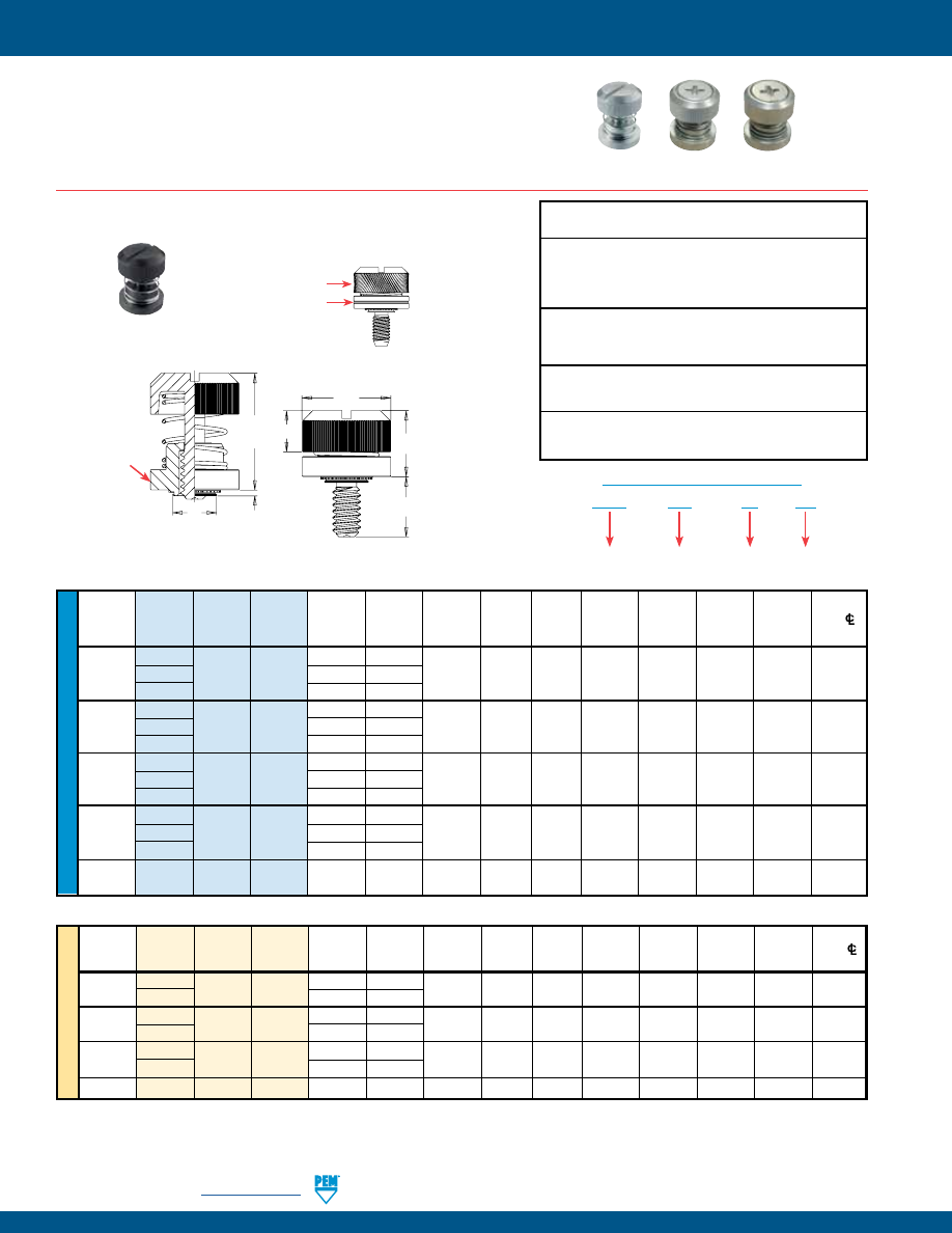
PF-12
PennEngineering •
www.pemnet.com
PEM® PF30™/PF50™/PF60™ CAPTIVE PANEL SCREWS
ME
TR
IC
U
NIF
IE
D
Screw A
Min.
Hole Size
E
Min. Dist.
Thread Thread
Length (Shank)
Sheet
In Sheet
C
±.010
G H T
1
T
2
Hole
C/L
Size
Type Code
Code Max.
Thickness
+ .003
Max.
± .015
± .005
Max.
Nom.
To Edge
-
.000
PF30 .030
.030
.112-40
PF31 440 30 .038 .040 .203 .202 .406 .300 .202 .325 .595 .26
(#4-40)
PF32
.058 .060
PF30 .030
.030
.138-32
PF31 632 30 .038 .040 .219 .218 .438 .300 .202 .325 .595 .28
(#6-32)
PF32
.058 .060
PF30 .030
.030
.164-32
PF31 832 30 .038 .040 .250 .249 .468 .300 .207 .330 .600 .29
(#8-32)
PF32
.058 .060
PF30 .030
.030
.190-32
PF31 032 30 .038 .040 .312 .311 .530 .300 .220 .335 .605 .33
(#10-32)
PF32
.058 .060
.250-20
PF32 0420 35 .058 .060 .375 .374 .625 .350 .242 .385 .675 .38
(1/4-20)
All dimensions are in inches.
All dimensions are in millimeters.
Thread
Screw
A
Min.
Hole Size
E
Min. Dist.
Size x
Type
Thread
Length
(Shank)
Sheet
In Sheet
C G H T
1
T
2
Hole
C/L
Pitch
Code
Code
Max.
Thickness
+ 0.08
Max.
±0.25
± 0.4
± 0.13
Max.
Nom.
To Edge
M3 x 0.5
PF31
M3 30
0.97 1
5.5 5.48 10.31 7.62
5.13 8.26 15.11
6.6
PF32
1.48
1.5
M4 x 0.7
PF31
M4 30
0.97 1
6.4 6.38 11.89 7.62 5.26 8.38 15.24 7.37
PF32
1.48
1.5
M5 x 0.8
PF31
M5 30
0.97 1
8
7.98 13.46 7.62 5.59 8.51 15.37 8.38
PF32
1.48
1.5
M6 x 1
PF32
M6
35
1.48
1.5
9.5
9.48
15.88
8.89
6.12
9.78
17.15
9.65
Available with
DuraBlack
TM
finish
(Finish Code “BN”)
PF30 – 832 – 30
CN
PART NUMBER DESIGNATION
Type and
Shank Code
Thread Size
Code
Screw
Length Code
Finish
Code
(1) As with all Class 2A/6g external threads with an additive finish, the maximum major and pitch, after plating, may equal basic sizes and be gauged to
Class 3A/4h, per ANSI B1.1, Section 8, Table 3A and ANSI B1.13M, Section 8, Paragraph 8.2.
Threads:
External, ASME B1.1, 2A / ASME B1.13M, 6g
(1)
Material:
Retainer: Carbon Steel
Screw: Hardened Carbon Steel (#4-40 and M3 sizes only)
Carbon Steel (all other sizes)
Spring: 300 Series Stainless Steel
Finish
:
Retainer: CN - Bright nickel over copper flash per ASTM B689
Screw: CN - Bright nickel over copper flash per ASTM B689
Spring: Natural Finish
Optional Finish
:
Retainer: BN - Black nitride, AMS2753, Section 3
Screw: BN - Black nitride, AMS2753, Section 3
For use in sheet hardness:
HRB 60 or less (Hardness Rockwell “B” Scale)
HB 107 or less (Hardness Brinell)
•
Low-profile design satisfies many functional and cosmetic requirements.
•
Convenient large head for tool or finger operation.
•
PF50/PF60 are available with Torx® recess.
•
PF50/PF60 are available with MAThread® anti cross-thread
technology. (See page 4 for more information).
PF50
Knurled Cap
PF60
Smooth Cap
PF30
Knurled Cap
PF30™ LOW-PROFILE CAPTIVE PANEL SCREWS
Installation Data page 31. Performance Data page 38.
Diagonal knurl and
groove on retainer
identifies metric
thread sizes.
H
E
C
G
A
T
2
T
1
Shoulder
provides
positive
stop during
installation.
Clinching profile may vary.
pem-html.html
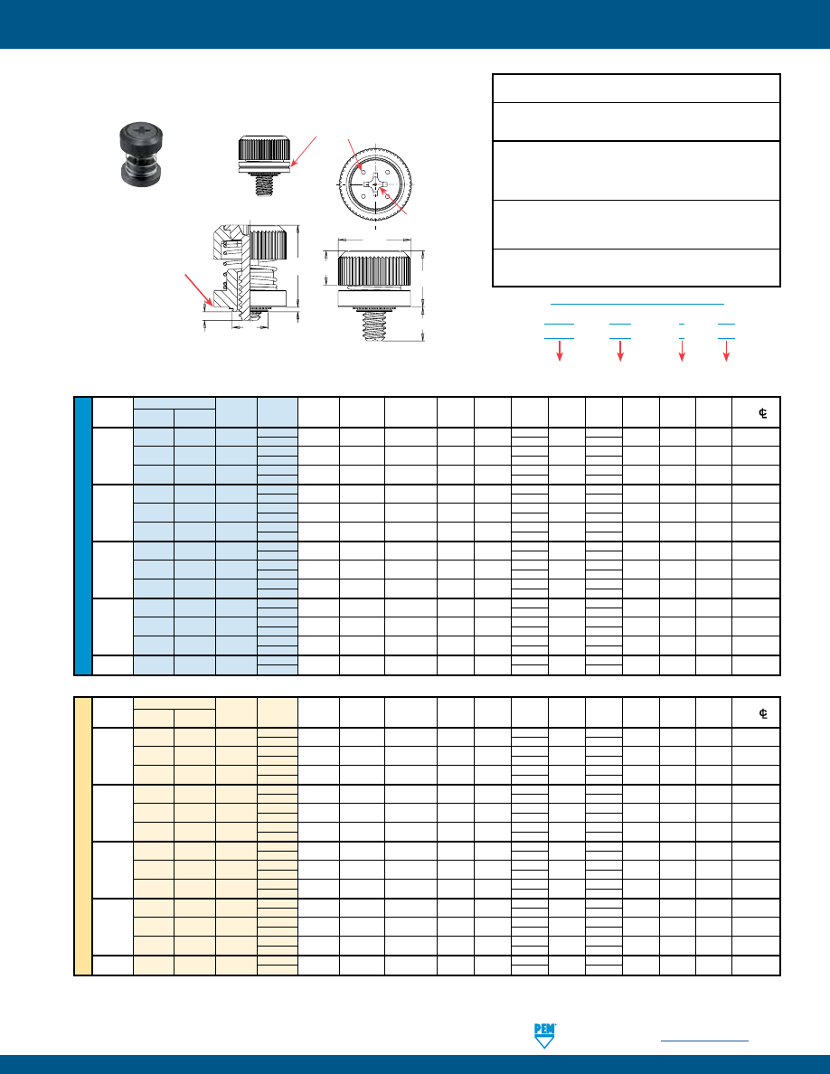
PennEngineering •
www.pemnet.com
PF-13
PEM® PF30™/PF50™/PF60™ CAPTIVE PANEL SCREWS
U
NIF
IE
D
All dimensions are in inches.
Type
Screw
A
Min.
Hole Size
E
Min. Dist
Thread Knurled Smooth Thread Length
(Shank)
Sheet
In Sheet
C
+.015
G H P T
1
T
2
Driver
Hole
C/L
Size
Cap
Cap
Code
Code
Max.
Thickness
+ .003 -.000
Max.
–.005
±.025
±.008
±.025
Max.
Nom.
Size
To Edge
PF50 PF60 440 0 .030 .030
.203 .202 .406 .230 .207 .000 .340 .520 #1 .26
1
.290
.060
.112-40
PF51 PF61 440 0 .038 .040
.203 .202 .406 .230 .207 .000 .340 .520 #1 .26
(#4-40)
1
.290
.052
PF52 PF62 440 0 .058 .060
.203 .202 .406 .230 .207 .000 .340 .520 #1 .26
1
.290
.032
PF50 PF60 632 0 .030 .030
.219 .218 .438 .230 .207 .000 .340 .520 #2 .28
1
.290
.060
.138-32
PF51 PF61 632 0 .038 .040
.219 .218 .438 .230 .207 .000 .340 .520 #2 .28
(#6-32)
1
.290
.052
PF52 PF62 632 0 .058 .060
.219 .218 .438 .230 .207 .000 .340 .520 #2 .28
1
.290
.032
PF50 PF60 832 0 .030 .030
.250 .249 .468 .230 .217 .000 .340 .520 #2 .29
1
.290
.060
.164-32
PF51 PF61 832 0 .038 .040
.250 .249 .468 .230 .217 .000 .340 .520 #2 .29
(#8-32)
1
.290
.052
PF52 PF62 832 0 .058 .060
.250 .249 .468 .230 .217 .000 .340 .520 #2 .29
1
.290
.032
PF50 PF60 032 0 .030 .030
.312 .311 .530 .230 .225 .000 .340 .530 #2 .33
1
.290
.060
.190-32
PF51 PF61 032 0 .038 .040 .312 .311 .530 .230 .225 .000 .340 .530 #2 .33
(#10-32)
1
.290
.052
PF52 PF62 032 0 .058 .060 .312 .311 .530 .230 .225 .000 .340 .530 #2 .33
1
.290
.032
.250-20
PF52 PF62 0420 0 .058 .060
.375 .374 .625 .280 .246 .000 .395 .600 #2 .38
(1/4-20)
1
.340 .060
Available with
DuraBlack
TM
finish
(Finish Code “BN”)
(1) As with all Class 2A/6g external threads with an additive finish, the maximum major and pitch, after plating, may equal basic sizes and be gauged to
Class 3A/4h, per ANSI B1.1, Section 8, Table 3A and ANSI B1.13M, Section 8, Paragraph 8.2.
ME
TR
IC
All dimensions are in millimeters.
Thread
Type
Screw
A
Min.
Hole Size
E
Min. Dist
Size x
Knurled Smooth Thread Length
(Shank)
Sheet
In Sheet
C
+0.4
G H P T
1
T
2
Driver
Hole
C/L
Pitch
Cap
Cap
Code
Code
Max.
Thickness
+ 0.08
Max.
–0.13
±0.64
±0.2
±0.64
Max.
Nom.
Size
To Edge
PF50 PF60 M3 0 0.77 0.8
5.5 5.48 10.3 5.84 5.26 0 8.64 13.21 #1 6.6
1
7.37
1.52
M3 x 0.5
PF51 PF61 M3 0 0.97 1
5.5 5.48 10.3 5.84 5.26 0 8.64 13.21 #1 6.6
1
7.37
1.32
PF52 PF62 M3 0 1.48 1.5
5.5 5.48 10.3 5.84 5.26 0 8.64 13.21 #1 6.6
1
7.37
0.81
PF50 PF60 M3.5 0 0.77 0.8
5.56 5.54 11.1 5.84 5.26 0 8.64 13.21 #2 7.1
1
7.37
1.52
M3.5 x 0.6
PF51 PF61 M3.5 0 0.97 1
5.56 5.54 11.1 5.84 5.26 0 8.64 13.21 #2 7.1
1
7.37
1.32
PF52 PF62 M3.5 0 1.48 1.5
5.56 5.54 11.1 5.84 5.26 0 8.64 13.21 #2 7.1
1
7.37
0.81
PF50 PF60 M4 0 0.77 0.8
6.4 6.38 11.9 5.84 5.51 0 8.64 13.46 #2 7.4
1
7.37
1.52
M4 x 0.7
PF51 PF61 M4 0 0.97 1
6.4 6.38 11.9 5.84 5.51 0 8.64 13.46 #2 7.4
1
7.37
1.32
PF52 PF62 M4 0 1.48 1.5
6.4 6.38 11.9 5.84 5.51 0 8.64 13.46 #2 7.4
1
7.37
0.81
PF50 PF60 M5 0 0.77 0.8
8 7.98 13.5 5.84 5.72 0 8.64 13.46 #2 8.4
1
7.37
1.52
M5 x 0.8
PF51 PF61 M5 0 0.97 1
8 7.98 13.5 5.84 5.72 0 8.64 13.46 #2 8.4
1
7.37
1.32
PF52 PF62 M5 0 1.48 1.5
8 7.98 13.5 5.84 5.72 0 8.64 13.46 #2 8.4
1
7.37
0.81
M6 x 1
PF52 PF62 M6 0 1.48 1.5
9.5 9.48 15.9 7.11 6.25 0 10.04 15.24 #2 9.7
1
8.64
1.52
PF50 – 440 – 1
CN
PF60 – 440 – 1
CN
PART NUMBER DESIGNATION
Type and
Shank Code
Thread Size
Code
Screw
Length Code
Finish
Code
Threads:
External, ASME B1.1, 2A / ASME B1.13M, 6g
(1)
Material:
Knob: Carbon Steel
Retainer: Carbon Steel
Screw: Carbon Steel
Spring: 300 Series Stainless Steel
Finish
:
Knob: CN - Bright nickel over copper flash per ASTM B689
Retainer: CN - Bright nickel over copper flash per ASTM B689
Screw: CN - Bright nickel over copper flash per ASTM B689
Spring: Natural Finish
Optional Finish
:
Knob: BN - Black Nitride, AMS2753, Section 3
Retainer: BN - Black Nitride, AMS2753, Section 3
Screw: BN - Black Nitride, AMS2753, Section 3
For use in sheet hardness:
HRB 60 or less (Hardness Rockwell “B” Scale)
HB 107 or less (Hardness Brinell)
PF50™ AND PF60™ LOW-PROFILE CAPTIVE PANEL
SCREWS
Installation Data page 31. Performance Data page 39.
Groove on retainer and dimples on
head designate metric thread.
E
T
1
G
A
P
T
2
C
H
Phillips
driver size.
(See chart)
Shoulder
provides
positive
stop during
installation.
Clinching profile may vary.
pem-html.html
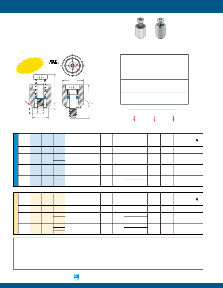
PF-14
PennEngineering •
www.pemnet.com
PEM® PFC4™/PFC2P™
CAPTIVE PANEL SCREWS
ME
TR
IC
U
NIF
IE
D
Screw A
Min.
Hole
Size
Min. Dist.
Thread
Thread
Length (Shank)
Sheet
In Sheet
C
E
G
P
T
1
T
2
Driver
Hole
C/L
Size
Type Code
Code Max.
Thickness
+ .003
Max.
± .010
± .016
±.025
Max.
Nom.
Size
To Edge
-
.000
.112-40
PFC4 440
40
.060 .060 .265 .264 .344
.250 .000
.370 .540 #1
.25
(#4-40) 62
.375 .125
40
.250
.000
.138-32 PFC4 632 62 .060 .060 .281 .280 .375 .375 .125 .380 .540 #2
.28
(#6-32)
84
.500
.250
50 .312
.000
.164-32 PFC4 832 72 .060 .060 .312 .311 .406 .437 .125 .480 .705 #2
.31
(#8-32)
94
.562
.250
50 .312
.000
.190-32 PFC4 032 72 .060 .060 .344 .343 .437 .437 .125 .490 .705 #2
.34
(#10-32)
94
.562 .250
All dimensions are in inches.
All dimensions are in millimeters.
Screw A
Min.
Hole Size
Min. Dist
Thread Thread
Length (Shank)
Sheet
In Sheet C E G P
T
1
T
2
Driver
Hole
C/L
Size
Type Code
Code Max.
Thickness
+ 0.08
Max.
± 0.25
± 0.4
±0.64
Max.
Nom.
Size
To Edge
x Pitch
M3 x 0.5
PFC4
M3
40
1.53 1.53 6.73 6.71 8.74
6.4 0
9.4 13.72 #1 6.35
62 9.5 3.2
50 7.9 0
M4 x 0.7
PFC4
M4
72
1.53
1.53
7.92
7.9
10.31
11.1
3.2
12.19
17.91
#2
7.87
94
14.3
6.4
50 7.9 0
M5 x 0.8
PFC4
M5
72
1.53
1.53
8.74
8.72
11.1
11.1
3.2
12.45
17.91
#2
8.63
94
14.3
6.4
PFC4 – 832 – 50
PART NUMBER DESIGNATION
Type and
Material
Thread Size
Code
Screw Length
Code
PFC4™ RECESSED-HEAD CAPTIVE PANEL SCREWS
Threads:
External, ASME B1.1, 2A / ASME B1.13M, 6g
Material:
Retainer: 400 Series Stainless Steel
Screw: 400 Series Stainless Steel
Spring: 300 Series Stainless Steel
Retaining Ring: Nylon, temperature limit 200˚ F / 93˚ C
Finish
:
Retainer: Passivated and/or tested per ASTM A380
Screw: Passivated and/or tested per ASTM A380
Spring: Natural Finish
For use in sheet hardness:
HRB 88 or less (Hardness Rockwell “B” Scale)
HB 183 or less (Hardness Brinell)
•
PFC4/PFC2P have fully concealed-head for tool only access.
•
PFC4/PFC2P comply with UL 60950 standards.
•
PFC4 installs into stainless steel sheets HRB 88 or less.
•
PFC4/PFC2P are available with MAThread® anti cross-thread technology.
(See page 4 for more information).
•
PFC4/PFC2P available with Torx® recess.
PFC4
PFC2P
Installation Data page 32. Performance Data page 39.
Dimples on head
designates metric
thread.
T
2
T
1
E
C
A
G
Phillips
driver size.
(See chart)
PEM
Trademark
Blue plastic
retaining ring.
P
Shoulder
provides
positive
stop during
installation.
Clinching profile may vary.
INST
ALLS
INTO
STAINL
ESS S
TEEL
A NOTE ABOUT FASTENERS FOR STAINLESS STEEL PANELS
In order for self-clinching fasteners to work properly, the fastener must be harder than the sheet into which it is being installed. In the case of stainless steel panels,
fasteners made from 300 Series Stainless Steel do not meet this hardness criteria. It is for this reason that 400 series fasteners are offered (PFC4). However, while
these 400 Series fasteners install and perform well in 300 Series stainless sheets they should not be used if the end product:
•
Will be exposed to any appreciable corrosive presence.
•
Requires non-magnetic fasteners.
•
Will be exposed to any temperatures above 300˚F (149˚C)
If any of the these are issues, please contact
techsupport@pemnet.com
for other options.
pem-html.html
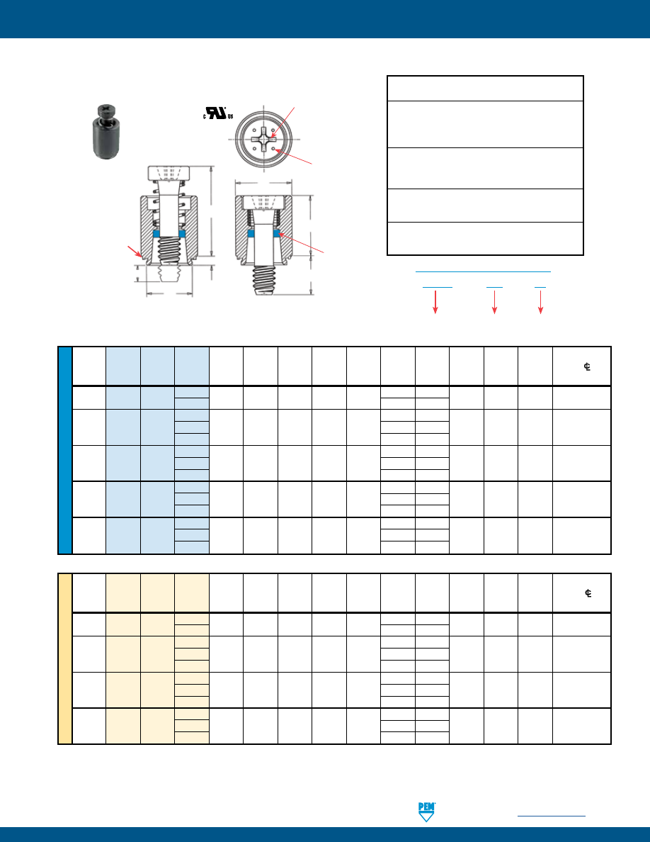
PennEngineering •
www.pemnet.com
PF-15
PEM® PFC4™/PFC2P™ CAPTIVE PANEL SCREWS
ME
TR
IC
U
NIF
IE
D
Screw A
Min.
Hole
Size
Min. Dist.
Thread
Thread
Length (Shank)
Sheet
In Sheet
C
E
G
P
T
1
T
2
Driver
Hole
C/L
Size
Type Code
Code Max.
Thickness
+ .003
Max.
± .010
± .016
±.025
Max.
Nom.
Size
To Edge
-
.000
.112-40
PFC2P 440
40
.060 .060 .265 .264 .312
.250 .000
.370 .540 #1
.25
(#4-40)
62
.375
.125
40
.250
.000
.138-32 PFC2P 632 62 .060 .060 .281 .280 .344 .375 .125 .380 .540 #2
.28
(#6-32)
84
.500
.250
50 .312
.000
.164-32 PFC2P 832 72 .060 .060 .312 .311 .375 .437 .125 .480 .705 #2
.31
(#8-32)
94
.562
.250
50 .312
.000
.190-32 PFC2P 032 72 .060 .060 .344 .343 .406 .437 .125 .490 .705 #2
.34
(#10-32)
94
.562
.250
60
.375
.000
.250-20 PFC2P 0420 82 .060 .060 .413 .412 .468 .500 .125 .620 .905 #3
.38
(1/4-20)
04
.625
.250
Screw A
Min.
Hole Size
Min. Dist
Thread Thread
Length (Shank)
Sheet
In Sheet C E G P T
1
T
2
Driver
Hole
C/L
Size x
Type Code
Code Max.
Thickness
+ 0.08
Max.
± 0.25
± 0.4
±0.64
Max.
Nom.
Size
To Edge
Pitch
M3 x 0.5
PFC2P
M3
40
1.53 1.53 6.73 6.71 7.92
6.4 0
9.4 13.72 #1
6.35
62 9.5
3.2
50 7.9 0
M4 x 0.7
PFC2P
M4
72
1.53
1.53
7.92
7.9
9.53
11.1
3.2
12.19
17.91
#2
7.87
94
14.3
6.4
50 7.9 0
M5 x 0.8
PFC2P
M5
72
1.53
1.53
8.74
8.72
10.31
11.1
3.2
12.45
17.91
#2
8.63
94
14.3
6.4
60 9.5 0
M6 x 1
PFC2P
M6
82
1.53
1.53
10.49
10.47
11.89
12.7
3.2
15.75
22.99
#3
9.65
04 15.9
6.4
PFC2P – 832 – 50
PART NUMBER DESIGNATION
Type and
Material
Thread Size
Code
Screw
Length Code
All dimensions are in inches.
All dimensions are in millimeters.
Threads:
External, ASME B1.1, 2A / ASME B1.13M, 6g
Material:
Retainer: 300 Series Stainless Steel
Screw: 400 Series Stainless Steel
Spring: 300 Series Stainless Steel
Retaining Ring: Nylon, temperature limit 200˚ F / 93˚ C
Finish
:
Retainer: Passivated and/or tested per ASTM A380
Screw: Passivated and/or tested per ASTM A380
Spring: Natural Finish
Optional Finish
:
Retainer: BN - Black nitride, AMS2753, Section 3
Screw: BN - Black nitride, AMS2753, Section 3
For use in sheet hardness:
HRB 70 or less (Hardness Rockwell “B” Scale)
HB 125 or less (Hardness Brinell)
PFC2P™ RECESSED-HEAD CAPTIVE PANEL SCREWS
Installation Data page 32. Performance Data page 39.
T
2
T
1
E
P
C
A
G
Dimples on head
designates metric
thread.
PEM
Trademark
Blue plastic
retaining ring.
Phillips
driver size.
(See chart)
Shoulder
provides
positive
stop during
installation.
Available with
DuraBlack
TM
finish
(Finish Code “BN”)
Clinching profile may vary.
pem-html.html
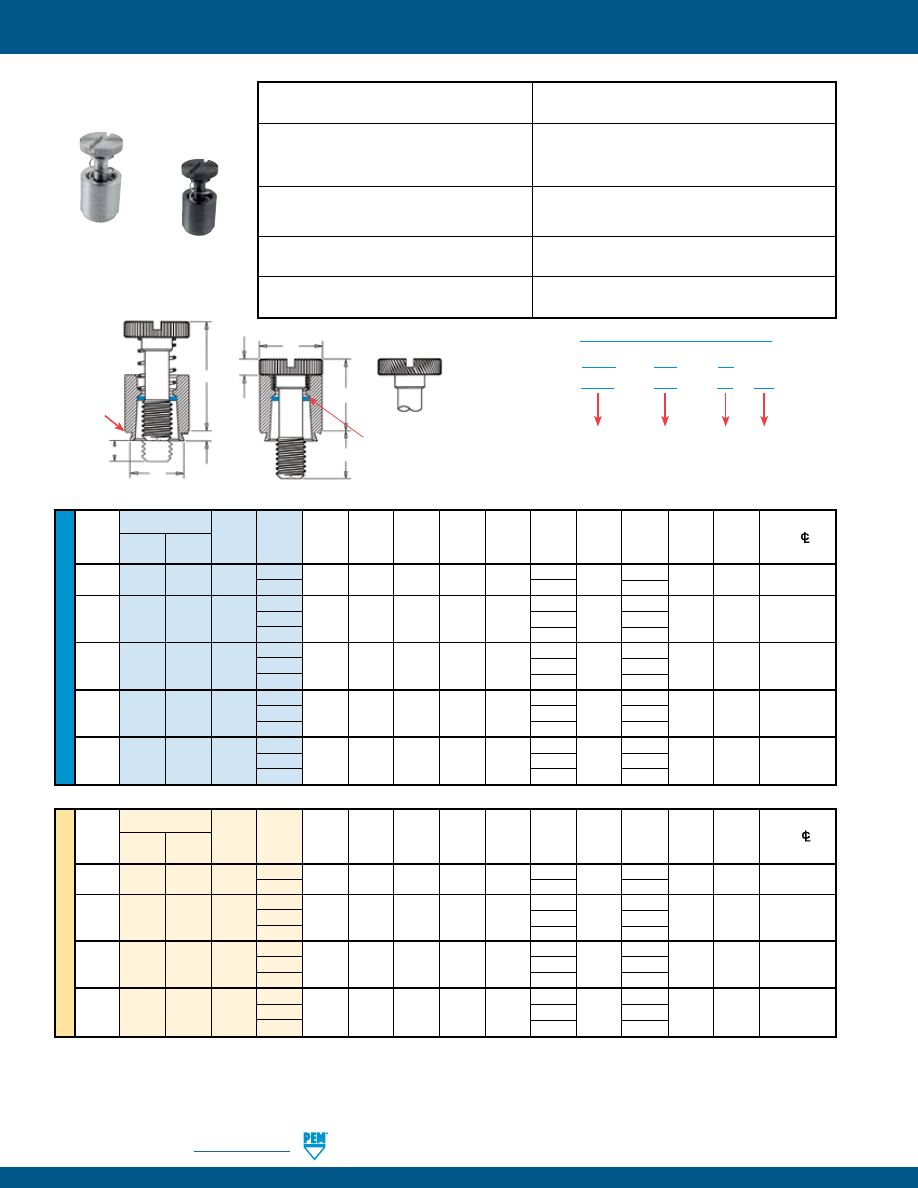
PF-16
PennEngineering •
www.pemnet.com
PEM Trademark
Blue plastic
retaining ring
T
2
T
1
C
A
G
H
E
Diagonal knurl identifies
metric thread sizes.
P
Shoulder
provides
positive
stop during
installation.
Clinching profile may vary.
PEM® PFC2™/PFS2™ CAPTIVE PANEL SCREWS
ME
TR
IC
U
NIF
IE
D
Type
Screw A
Min.
Hole Size
E
Min. Dist.
Thread Thread
Length (Shank)
Sheet
In Sheet C
G H P T
1
T
2
Hole
C/L
Size x Stainless
Code Code Max. Thickness + 0.08
Max.
±.25
± 0.4
± 0.13
±0.64
Max.
Nom.
To Edge
Pitch
Steel
Steel
M3 x 0.5
PFC2
PFS2
M3 40 1.53 1.53 6.73 6.71 7.92 6.4 1.83 0 9.14 13.72 6.35
62 9.5 3.2
50 7.9 0
M4 x 0.7
PFC2
PFS2
M4
72
1.53
1.53
7.92
7.9
9.53
11.1
2.08
3.2
11.43
17.53
7.87
94
14.3
6.4
50 7.9 0
M5 x 0.8
PFC2
PFS2
M5
72
1.53
1.53
8.74
8.72
10.31
11.1
2.08
3.2
11.47
17.53
8.63
94
14.3
6.4
60 9.5 0
M6 x 1
PFC2
PFS2
M6
82
1.53
1.53
10.49
10.47
11.89
12.7
2.46
3.2
14.73
22.35
9.65
04 15.9
6.4
Type
Screw A
Min.
Hole
Size
Min. Dist.
Thread
Thread Length (Shank) Sheet In Sheet
C
E
G
H
P
T
1
T
2
Hole
C/L
Size Stainless
Code Code Max. Thickness + .003
Max.
± .010
±.016
±.005
±.025
Max.
Nom.
To Edge
Steel
Steel -
.000
.112-40
PFC2 PFS2 440
40
.060 .060 .265 .264 .312
.250
.072
.000
.360 .540
.25
(#4-40)
62
.375
.125
40
.250
.000
.138-32 PFC2 PFS2 632 62 .060 .060 .281 .280 .344 .375 .072 .125 .360 .540
.28
(#6-32)
84
.500
.250
50 .312
.000
.164-32 PFC2 PFS2 832 72 .060 .060 .312 .311 .375 .437 .082 .125 .450 .690
.31
(#8-32)
94
.562
.250
50 .312
.000
.190-32 PFC2 PFS2 032 72 .060 .060 .344 .343 .406 .437 .082 .125 .450 .690
.34
(#10-32)
94
.562
.250
60
.375
.000
.250-20
PFC2 PFS2 0420 82 .060 .060 .413 .412 .468 .500 .097 .125 .580 .880
.38
(1/4-20)
04
.625
.250
All dimensions are in inches.
All dimensions are in millimeters.
PFS2 is available with
DuraBlack
TM
finish
(Finish Code “BN”)
(1) As with all Class 2A/6g external threads with an additive finish, the maximum major and pitch, after plating, may equal basic sizes and be gauged to
Class 3A/4h, per ANSI B1.1, Section 8, Table 3A and ANSI B1.13M, Section 8, Paragraph 8.2.
(2) The blue plastic retaining rings are a PEM trademark. The temperature limit is 200° F / 93° C.
PFS2
Threads:
External, ASME B1.1, 2A / ASME B1.13M, 6g
(1)
Material:
Retainer: Hardened Carbon Steel
(2)
Screw: Carbon Steel
Spring: 300 Series Stainless Steel
Retaining Ring: Nylon, temperature limit 200˚ F / 93˚ C
Finish:
Retainer: CN - Bright nickel over copper flash per ASTM B689
Screw: CN - Bright nickel over copper flash per ASTM B689
Spring: Natural Finish
Optional Finish:
Retainer: BN - Black nitride, AMS2753, Section 3
Screw: BN - Black nitride, AMS2753, Section 3
For use in sheet hardness:
HRB 80 or less (Hardness Rockwell “B” Scale)
HB 150 or less (Hardness Brinell)
PFC2
Threads:
External, ASME B1.1, 2A / ASME B1.13M, 6g
Material:
Retainer: 300 Series Stainless Steel
(2)
Screw: 300 Series Stainless Steel
Spring: 300 Series Stainless Steel
Retaining Ring: Nylon, temperature limit 200˚ F / 93˚ C
Finish:
Retainer: Passivated and/or tested per ASTM A380
Screw: Passivated and/or tested per ASTM A380
Spring: Natural Finish
Optional Finish:
Retainer: BN - Black nitride, AMS2753, Section 3
Screw: BN - Black nitride, AMS2753, Section 3
For use in sheet hardness:
HRB 70 or less (Hardness Rockwell “B” Scale)
HB 125 or less (Hardness Brinell)
PFC2/PFS2
PFS2 – 832 – 50
CN
PART NUMBER DESIGNATION
Type and
Material
Thread Size
Code
Screw
Length
Code
Finish
Code
PFC2 – 832 – 50
Installation Data page 33. Performance Data page 39.
pem-html.html
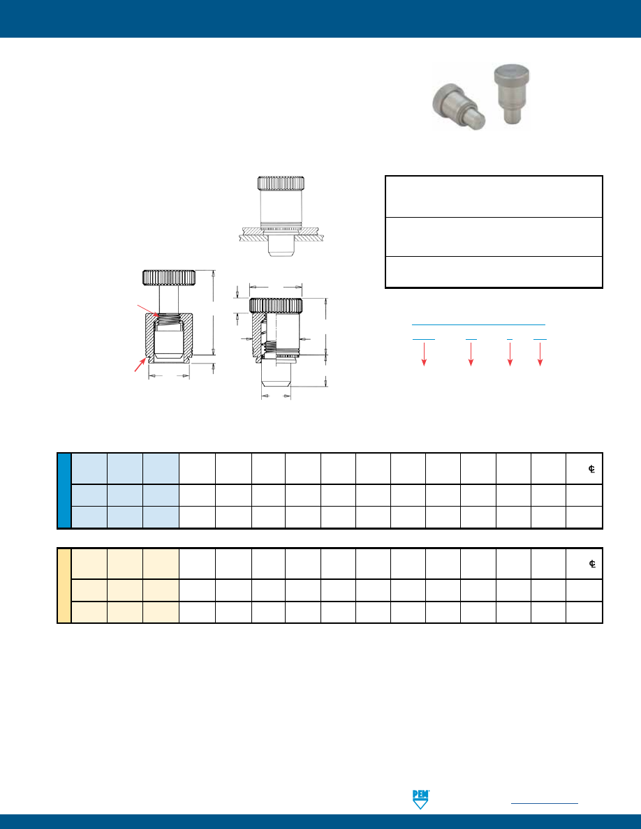
PennEngineering •
www.pemnet.com
PF-17
•
Used as positioning pins for sliding components such as drawer slides and equipment consoles.
•
Fast installation and removal of components.
•
Reverse side of sheet is flush when plunger is retracted.
•
PTL2 has quick lockout feature to hold plunger in fully retracted position.
•
For use in sheets of HRB 80 or less.
•
Available as PSL2 without lockout feature on special order.
PEM® PTL2™/PSL2™ SPRING-LOADED PLUNGER ASSEMBLIES
ME
TR
IC
U
NIF
IE
D
Plunger
Plunger
A Min.
Hole
Size
D
Min.
Dist.
Type
Diameter
Length
(Shank)
Sheet
In Sheet
C
+ .000
E
1
E
2
G H T
1
T
2
Hole
C/L
Code
Code
Max.
Thickness +.003 -.000
Max.
- .005
± .010
± .010
± .010
± .010
± .010
Nom.
To Edge
PTL2 04 4 .058 .060 .328 .327 .250 .50 .406 .310 .17 .595 .895 .34
PSL2
(1)
04 4 .058 .060 .328 .327 .250 .50 .406 .310 .17 .510 .780 .34
Plunger
Plunger
A Min.
Hole
Size
Min.
Dist.
Type
Diameter
Length
(Shank)
Sheet
In Sheet
C D
E
1
E
2
G H T
1
T
2
Hole
C/L
Code
Code
Max.
Thickness
+ 0.08
Max.
- 0.13
± 0.25
± 0.25
± 0.25
± 0.25
± 0.25
Nom.
To Edge
PTL2 04 4 1.47 1.53 8.33 8.31 6.35 12.7 10.3 7.87 4.32 15.11 22.73 8.64
PSL2
(1)
04 4 1.47 1.53 8.33 8.31 6.35 12.7 10.3 7.87 4.32 12.95 19.81 8.64
All dimensions are in inches.
All dimensions are in millimeters.
PTL2 – 04 – 4
CN
PART NUMBER DESIGNATION
Type
Plunger
Diameter
Code
Plunger
Length
Code
Finish
Code
(1) Without lockout feature. Available on special order.
PTL2/PSL2 installed and with
mating panel. Minimum mating
hole diameter .251” / 6.38 mm.
Material:
Plunger: Hardened Carbon Steel
Retainer: Hardened Carbon Steel
Spring: 300 Series Stainless Steel
Finish
:
Plunger: CN - Bright nickel over copper flash per ASTM B689
Retainer: CN - Bright nickel over copper flash per ASTM B689
Spring: Natural Finish
For use in sheet hardness:
HRB 80 or less (Hardness Rockwell “B” Scale)
HB 150 or less (Hardness Brinell)
Installation Data page 33. Performance Data page 39.
E
1
E
2
T
2
T
1
C
D
G
H
A
Lockout feature holds
plunger in retracted
position. Simply
retract and twist
to engage lockout
feature.
Shoulder
provides
positive
stop during
installation.
Clinching profile may vary.
pem-html.html
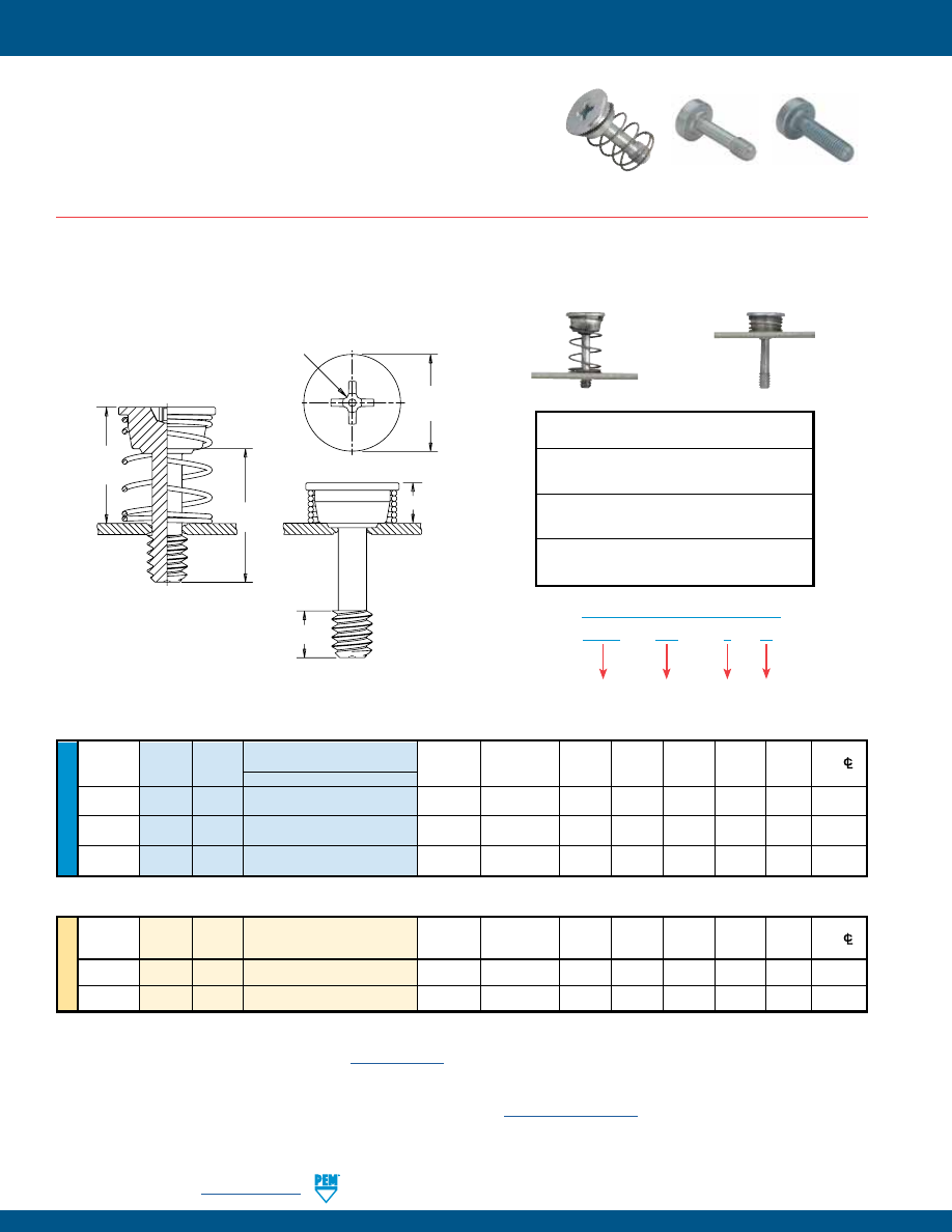
PF-18
PennEngineering •
www.pemnet.com
PEM® SCBR™/SCB™/SCBJ™ CAPTIVE PANEL SCREWS
U
NIF
IE
D
NOTE:
SCBR screws are shipped with mating springs.
For designs requiring a specific spring rate, contact our PEM Technical Support group at
techsupport@pemnet.com
.
All dimensions are in inches.
Length Code “L” ±.015
Min.
Hole Size
E
Min. Dist
Thread
Thread
(Length Code in 16ths of an inch)
Sheet
in Sheet
+.005
H
1
H
2
T
Driver Hole
C/L
Size
Type Code
.500
Thickness
+.003 –.000
–.010
±.005
Ref.
Nom.
Size
To Edge
.112-40
SCBR 440
8
.040
.112
.348 .165 .495 .130 #1 .175
(#4-40)
.138-32
SCBR 632
8
.040
.138
.381 .170 .500 .130 #2 .190
(#6-32)
.164-32
SCBR 832
8
.040
.164
.410 .175 .505 .130 #2 .205
(#8-32)
All dimensions are in millimeters.
ME
TR
IC
Thread
Min.
Hole Size
E
Min. Dist
Size x
Thread
Length Code “L” ±0.4
Sheet
in Sheet
+0.13
H
1
H
2
T Driver Hole
C/L
Pitch
Type
Code
(Length Code in millimeters)
Thickness
+0.08
–0.25
±0.13
Ref.
Nom.
Size
To Edge
M3 x 0.5
SCBR
M3
12
1.02
3
9.1
4.2
11.8
3.3
#1
4.5
M4 x 0.7 SCBR M4
12
1.02
4
10.7 4.5 12.1 3.3 #2 5.4
SCBR – 632 – 8
ZI
PART NUMBER DESIGNATION
Type
Thread
Size
Code
Length
Code
Finish
(1) As with all Class 2A/6g external threads with an additive finish, the maximum major and pitch, after plating, may equal basic sizes and be gauged to
Class 3A/4h, per ANSI B1.1, Section 8, Table 3A and ANSI B1.13M, Section 8, Paragraph 8.2.
(2) See PEM Technical Support section of our website (
www.pemnet.com
) for related plating standards and specifications.
SCBR engaged
SCBR retracted
SCBR™ SPINNING CLINCH BOLT WITH SELF-RETRACTING FEATURE
Threads:
External, ASME B1.1, 2A / ASME B1.13M, 6g
(1)
Material:
Screw - Hardened Carbon Steel
Spring - 300 series stainless steel
Finish
:
Screw - ZI - Zinc plated, 5µm, colorless (standard)
(2)
Spring: Natural Finish
For use in sheet hardness:
HRB 80 or less (Hardness Rockwell “B” Scale)
HB 150 or less (Hardness Brinell)
•
Permanently captivates into sheets as thin as .040” / 1.02 mm and greater.
•
Lowest cost captive screw design to replace loose hardware.
•
Available with self-retracting (SCBR), axial float (SCB), or jacking feature (SCBJ).
•
Appropriate for close centerline-to-edge applications.
SCBR
SCB
SCBJ
Installation Data page 34. Performance Data page 40.
H
2
H
1
L
T
E
Phillips
driver size.
(See chart)
pem-html.html
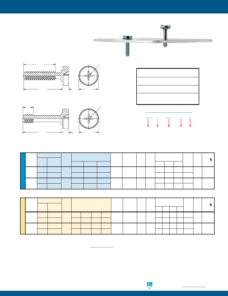
PennEngineering •
www.pemnet.com
PF-19
PEM® SCBR™/SCB™/SCBJ™ CAPTIVE PANEL SCREWS
ME
TR
IC
U
NIF
IE
D
SCB
J – 632 – 6
ZI
PART NUMBER DESIGNATION
Type
Jacking
(If applicable)
Thread
Size
Code
Length
Code
Finish
Type
Min.
Hole Size
T
Nom.
Min. Dist.
Thread
Thread
Sheet in
Sheet E H Nom. Axial
Driver
Hole
C/L
Size Jacking Non-jacking Code
.250 .375 .500
Thickness +.003 –.000 ±.010
Nom.
– 4 – 6 – 8
Float
Size
To Edge
.112-40 SCBJ —
440
4 6 8
.040
.112 .250 .080
.160 .285 .410
—
#1 .13
(#4-40) — SCB
—
—
8
— — .130 .330
.138-32 SCBJ —
632
4 6 8
.040
.138 .291 .080
.160 .285 .410
—
#2 .15
(#6-32) — SCB
—
—
8
— — .130 .330
Length Code “L” ±.015
(Length Code in 16ths of an inch)
Thread Type
Min.
Hole Size
T
Nom.
Min. Dist.
Size x Thread
Sheet
in Sheet
E
H
Nom.
Axial
Driver Hole
C/L
Pitch Jacking Non-jacking Code
Thickness +0.08 ±0.25 Nom. – 6 –10 –12 -14 Float Size To Edge
M3 x 0.5
SCBJ
—
M3
6 10 12 14
1.02
3 6.6 2.03
3.7 7.7 9.7
11.7
—
#1 3.3
—
SCB
—
—
12
14
— — 3.3 5.3 7.67
M4 x 0.7
SCBJ
—
M4
6 10 12 14
1.02
4 8.28 2.03
3.7 7.7 9.7
11.7
—
#2 5
—
SCB
—
—
12
14
— — 3.3 5.3 7.67
Length Code “L” ±0.4
(Length Code in millimeters)
All dimensions are in inches.
All dimensions are in millimeters.
(1) As with all Class 2A/6g external threads with an additive finish, the maximum major and pitch, after plating, may equal basic sizes and be gauged to
Class 3A/4h, per ANSI B1.1, Section 8, Table 3A and ANSI B1.13M, Section 8, Paragraph 8.2.
(2) See PEM Technical Support section of our website (
www.pemnet.com
) for related plating standards and specifications.
SCB with
axial float.
SCBJ with
jacking feature.
Threads:
External, ASME B1.1, 2A / ASME B1.13M, 6g
(1)
Material:
Hardened Carbon Steel
Finish
:
ZI - Zinc plated, 5µm, colorless (standard)
(2)
For use in sheet hardness:
HRB 80 or less (Hardness Rockwell “B” Scale)
HB 150 or less (Hardness Brinell)
SCB™/SCBJ™ SPINNING CLINCH BOLTS
Installation Data page 34. Performance Data page 40.
SCB
L
H
T
E
Phillips
driver size.
(See chart)
SCBJ
E
T
L
H
Phillips
driver size.
(See chart)
pem-html.html
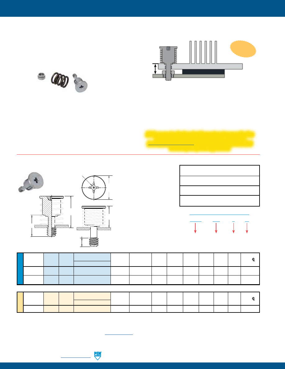
PF-20
PennEngineering •
www.pemnet.com
PEM® HSCB™ HEAT SINK MOUNTING SYSTEM
•
Screw can not be overtightened. Audible “click” when fully
engaged.
•
Screw and spring mount together permanently into the heat
sink.
•
Spring determines clamp force.
•
Receptacle nut mounts permanently to the PC board.
•
Provides even, constant contact of heat sink to chip
component.
•
Allows removal of heat sink if desired.
U
NIF
IE
D
All dimensions are in inches.
Length Code “L” ±.015
Min.
Hole Size
Screw
Min. Dist
Thread
Thread
Sheet
in Sheet
E
S
H
1
H
2
T
S
Factor Driver Hole
C/L
Size
Type
Code
.320
Thickness
+.003 –.000
±.010
Ref.
Ref.
Min.
(SF)
Size
To Edge
.112-40
HSCB 440
4
.040
.112
.312 .300 .470 .130 .170 #1 .156
(#4-40)
.138-32
HSCB 632
4
.040
.138
.352 .300 .470 .130 .170 #2 .178
(#6-32)
All dimensions are in millimeters.
ME
TR
IC
Thread
Length Code “L” ±0.4
Min.
Hole Size
Screw
Min. Dist
Size x
Thread
Sheet
in Sheet
E
S
H
1
H
2
T
S
Factor Driver Hole
C/L
Pitch
Type
Code
8.13
Thickness
+0.08
±0.25
Ref.
Ref.
Min.
(SF)
Size
To Edge
M3 x 0.5
HSCB
M3
3
1
3
8.18
7.67
12
3.3
4.32
#1
4.13
HSCB™ SELF-CAPTIVATING SCREW
NOTE:
HSCB screws, HSR nuts and HSL springs are sold separately.
(1) As with all Class 2A/6g external threads with an additive finish, the maximum major and pitch, after plating, may equal basic sizes and be gauged to
Class 3A/4h, per ANSI B1.1, Section 8, Table 3A and ANSI B1.13M, Section 8, Paragraph 8.2.
(2) See PEM Technical Support section of our website (
www.pemnet.com
) for related plating standards and specifications.
(3) HRB - Hardness Rockwell “B” Scale. HB - Hardness Brinell.
To select proper length code of nut/standoff:
1)
Determine “G”, the distance from the top surface of the heat sink to
the top of the P.C. Board.
2)
Find the combination of Screw (HSCB) and Nut (HSR) whose sum of
Screw Factor (SF) plus Nut Factor (NF) are closest to G.
3)
Find D = G – SF – NF. The D value must be a negative number
between zero and 1mm or 1/32” (1 dash length of HSR nut).
4)
The actual working load is equal to the Spring (HSL) Working Load
+ (D x spring rate k). Lower D value results in lower force.
The new HSCB™ engineered mounting system provides secure attachment of a heat sink to the circuit board while providing firm
contact to the chip component allowing optimum heat dissipation. The three-piece fastening system, sold individually, includes the
screw, spring and receptacle nut. The clamp load created is determined
by the spring rate and the amount of deflection that is designed into
the joint of the hardware. The system also allows for slight expansion
and contraction of the joint components without stress to the delicate
circuitry. The unique “click” feature lets the user know when the
fastener is completely installed.
Patented
If this or any standard product does not meet your application
needs, contact our PEM Technical Support group at
techsupport@pemnet.com
to develop a special product that
matches your specific application.
HSCB – 440 – 4
ZI
PART NUMBER DESIGNATION
Type
Thread
Size
Code
Length
Code
Finish
HSCB
HSR
HSL
G
NEW!
Installation Data page 35.
Performance Data page 40.
L
T
S
E
S
Phillips
driver size.
(See chart)
H
1
H
2
Threads:
External, ASME B1.1, 2A / ASME B1.13M, 6g
(1)
Material:
Hardened carbon steel
Finish
:
Screw - ZI - Zinc plated, 5µm, colorless
(2)
For use in sheet hardness:
HRB 80 / HB150 or less
(3)
pem-html.html
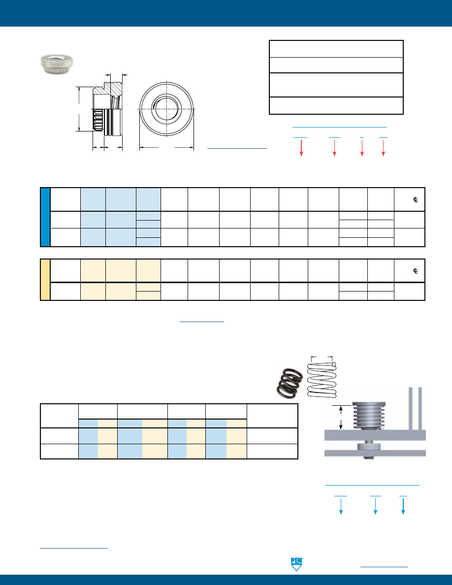
PennEngineering •
www.pemnet.com
PF-21
PEM® HSCB™ HEAT SINK MOUNTING SYSTEM
U
NIF
IE
D
A
Min.
Hole
Size
Nut
Min.
Dist.
Thread Thread
Length
(Shank)
Sheet In
Sheet C E
N
F T
N
Factor Hole
C/L
Size
Type
Code
Code Max. Thickness
+.003 –.000
±.003
±.005
±.010
±.005
(NF)
To Edge
.112-40
HSR 440
2
.060 .060 .166 .184 .219 .060
.065 .000
0.17
(#4-40)
3
.093
.031
.138-32
HSR 632
2
.060 .060 .213 .231 .281 .060
.065 .000
0.22
(#6-32)
3
.093
.031
All dimensions are in inches.
HSR™ BROACHING NUT/STANDOFF
ME
TR
IC
Thread
A
Min.
Hole Size
Nut
Min. Dist.
Size x
Thread
Length
(Shank)
Sheet
In Sheet
C
E
N
F T
N
Factor Hole
C/L
Pitch Type
Code
Code Max. Thickness
+0.08
±0.08
±0.13
±0.25
±0.13
(NF)
To Edge
M3 x 0.5
HSR
M3
2
1.53 1.53 4.22 4.68 5.56 1.3
2 .75
4.4
3
3
1.75
All dimensions are in millimeters.
NOTE:
HSCB screws, HSR nuts and HSL springs are sold separately.
(1) See PEM Technical Support section of our website (
www.pemnet.com
) for related plating standards and specifications.
(2) HRB - Hardness Rockwell “B” Scale. HB - Hardness Brinell.
HSR – 440 – 2
ET
PART NUMBER DESIGNATION
Type
Thread
Size
Code
Length
Code
Finish
HSL™ SPRINGS
HSL springs are engineered to provide a reliable and repeatable spring rate when
assembled with mating PEM hardware. The spring rate is critical to the successful
assembly of your heat sink. Clamp load will be determined by the spring rate and
deflection that is designed into the joint.
Working Height
Minimum
Load at
Working
Spring Rate
Part
Inside Dia.
Working Height ±10%
Height Ref.
k
Spring
Number (in.) (mm) (lbs.)
(N)
(in.) (mm) (lb/in) (N/mm)
Material
HSL-574-35 .226 5.74 7.87
35 .270 6.86 74 12.96
17-7 Stainless Steel,
Natural
Finish
HSL-701-35 .276 7.01 7.87
35 .270 6.86 39 6.84 17-7 Stainless Steel,
Natural
Finish
The HSL
Inside Diameter Code
is expressed in hundredths of millimeters.
Example “574” indicates a minimum inside diameter of 5.74mm or .226”.
The HSL
Load Code
is expressed in Newtons developed at the working height of the spring
once the joint is assembled.
Example “35” indicates working load of 35 Newtons, or approximately 8 lbs.
For designs requiring a specific spring rate, contact our PEM Technical Support group at
techsupport@pemnet.com
Spring I.D.
Min.
NOTE:
HSCB screws, HSR nuts and HSL springs are sold separately. HSL-574-35 spring fits screw
thread sizes #4-40 and M3 and HSL-701-35 spring fits screw thread size #6-32.
HSL – 574 – 35
PART NUMBER DESIGNATION
Type
Inside
Diameter
Code
Load
Code
Installation Data page 35. Performance Data page 40.
A
T
N
E
N
C
F
Threads:
Internal, ASME B1.1, 2B / ASME B1.13M, 6H
Material:
Carbon steel
Finish
:
ET - Electro-plated tin ASTM B 545, class B
with clear preservative coating, annealed
(1)
For use in sheet hardness:
HRB 60 / HB 107 or less
(2)
HSR nuts are available for
surface mounting. Contact our
PEM technical support group at
techsupport@pemnet.com
.
pem-html.html
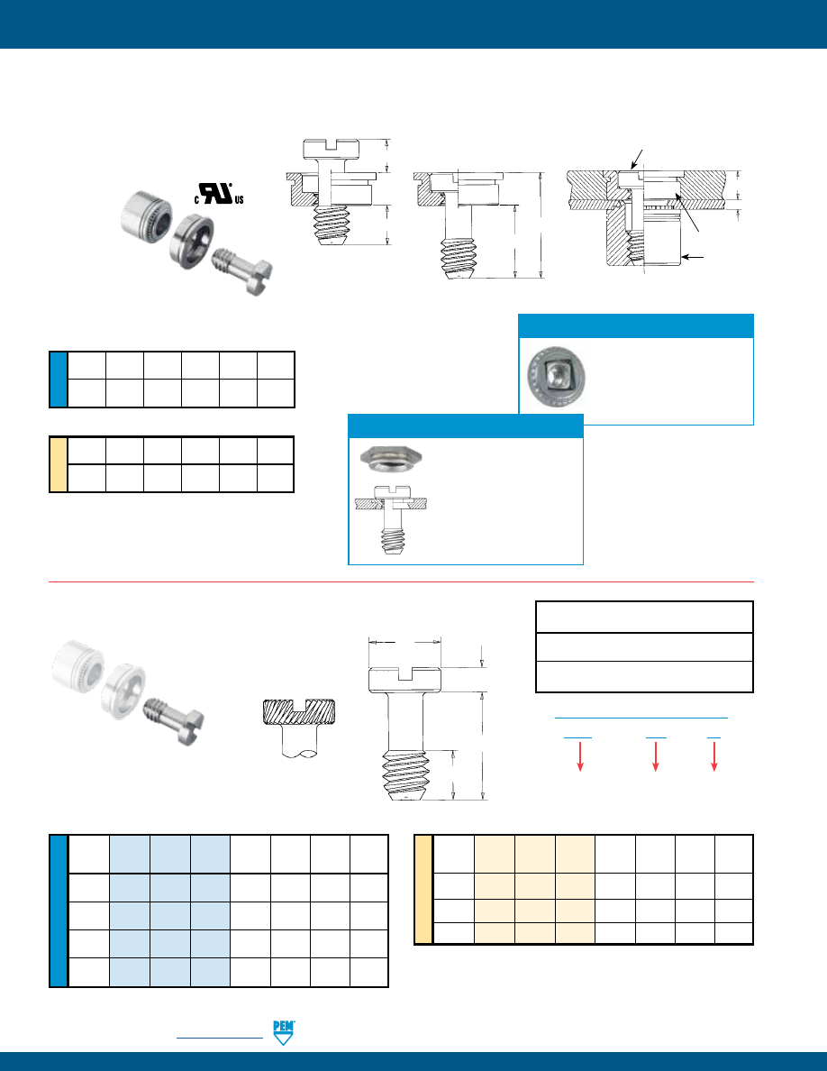
PF-22
PennEngineering •
www.pemnet.com
PEM® PF10™ FLUSH-MOUNTED CAPTIVE PANEL SCREWS
ME
TR
IC
U
NIF
IE
D
ME
TR
IC
U
NIF
IE
D
Thread Thread Screw E H L T
Size Type Code Length Nom.
+ .002
± .010
Nom.
Code -
.006
.112-40 PS10 440 40 .18 .075 .33 .13
(#4-40)
.138-32 PS10 632 40 .21 .075 .33 .13
(#6-32)
.164-32 PS10 832 40 .25 .075 .33 .13
(#8-32)
.190-32 PS10 032 40 .28 .075 .33 .13
(#10-32)
All dimensions are in inches.
PS10™ FLUSH MOUNTED SCREWS
A
B
G
M P T
Min.
Nom.
± .010
Nom.
.04
.125
.40
.16
.28
.13
All dimensions are in inches.
A
B
G
M P T
Min.
Nom.
± 0.25
Nom.
1
3.18 10.16 4.06 7.11 3.3
All dimensions are in millimeters.
PS10 Screw
Thread
Thread Screw E H L T
Size x
Type
Code Length Nom.
+ 0.05
± 0.25
Nom.
Pitch Code -
0.15
M3 x 0.5 PS10 M3 40 4.7 1.91 8.38 3.3
M4 x 0.7 PS10 M4 40 6.3 1.91 8.38 3.3
M5 x 0.8 PS10 M5 40
7.1 1.91 8.38 3.3
All dimensions are in millimeters.
E
H
L
T
Diagonal knurl
identifies metric
thread sizes.
Manually
Retracted
Position
M
T
P
G
N10 Receptacle Nut
PR10 Retainer
PS10 Screw
A
B
PS10 Screw
N10
Receptacle
Nut
PR10
Retainer
PS10 – 832 – 40
PART NUMBER DESIGNATION
Type and
Material
Thread Size
Code
Screw
Length
Code
Threads:
External, ASME B1.1, 2A / ASME B1.13M, 6g
Material:
300 Series Stainless Steel
Finish
:
Passivated and/or tested per ASTM A380
•
PF10 assembly sits flush in sheets as thin as .050” / 1.27 mm or flush on both sides in .125” / 3.2 mm sheets.
•
PS10 screw remains captive in retainer when disengaged.
•
PR10 retainer and F10 receptacle nut is for use in sheets of HRB 70 or less.
•
N10 nut is for use in sheets of HRB 80 or less.
•
Complies with UL 60950 standards.
Floating Receptacle Nuts
Available on special order
F10 self-clinching floating
receptacle nuts permit a
minimum of .015”/0.38mm
adjustment for mating hole
misalignment.
Installation Data page 36. Performance Data page 41.
Flush Fasteners as retainers
For applications where the
screw head may project
above the sheet surface,
PS10 screws may be used
with PEMSERT® F fasteners
as retainers. For dimensions
and engineering data on F
fasteners, see PEM Bulletin F.
pem-html.html
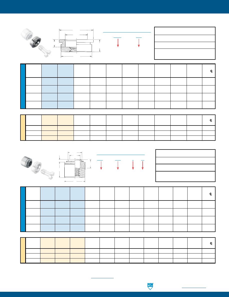
PennEngineering •
www.pemnet.com
PF-23
PEM® PF10™ FLUSH-MOUNTED CAPTIVE PANEL SCREWS
ME
TR
IC
U
NIF
IE
D
A
Min. Sheet
Min. Sheet
Hole
Size
Min. Dist.
Thread Type Thread (Shank)
for Self-
for Flush
in Sheet
B
C
E
H
Hole
C/L
Size
Code
Max.
Clinching Installation
+ .003
Nom.
Max.
Nom.
Nom.
to Edge
- .000
.112-40
PR10 440 .125 .050 .125 .281 .195 .280 .31 .075 .31
(#4-40)
.138-32
PR10 632 .125 .050 .125 .312 .225 .311 .34 .075 .33
(#6-32)
.164-32
PR10 832 .125 .050 .125 .344 .255 .343 .37 .075 .34
(#8-32)
.190-32
PR10 032 .125 .050 .125 .375 .290 .374 .41 .075 .36
(#10-32)
Thread
A
Min. Sheet
Min. Sheet
Hole Size
Min. Dist.
Size x
Type
Thread
(Shank)
for Self-
for Flush
in Sheet
B C E H Hole
C/L
Pitch
Code
Max.
Clinching
Installation
+ 0.08
Nom. Max. Nom. Nom.
to Edge
M3 x 0.5
PR10
M3
3.18
1.27
3.18
7.14
4.75
7.12
7.87
1.91
7.87
M4 x 0.7
PR10
M4
3.18
1.27
3.18
8.74
6.48
8.72
9.53
1.91
8.64
M5 x 0.8
PR10
M5
3.18
1.27
3.18
9.53
7.37
9.5
10.41
1.91
9.14
E
B
H
A
C
(1) The purpose of the thread is for component screw retention only, thread may not accept 2B/6H Go threaded plug gage, but class 3A/4h screw must
pass with finger torque, may not reject NoGo threaded plug gage and minor diameter may exceed 2B/6H maximum.
(2) 2B (unified) and 6H (metric) go gauge may stop at pilot end but class 3A (unified) and 4h (metric) screws will pass through with finger torque.
(3) See PEM Technical Support section of our website (
www.pemnet.com
) for related plating standards and specifications.
(4) Also available on special order F10 self-clinching floating receptacle nuts.
PR10
Retainer
PR10™ SELF-CLINCHING FLUSH-MOUNTED RETAINERS
PR10 – 832
PART NUMBER DESIGNATION
Type
Thread Size
Code
All dimensions are in inches.
All dimensions are in millimeters.
ME
TR
IC
U
NIF
IE
D
All dimensions are in inches.
All dimensions are in millimeters.
A
Min.
Hole
Size
Min. Dist.
Thread
Type Thread Shank (Shank)
Sheet
In Sheet
C
E
F
H
T
Hole
C/L
Size
Code
Code
Max.
Thickness
+ .003
Max.
Nom.
± .010
Nom.
± .005
To Edge
-
.000
.112-40
N10 440 1 .038 .040 .187 .186 .28 .130 .126 .24 .22
(#4-40)
.138-32
N10 632 1 .038 .040 .213 .212 .31 .130 .156 .24 .27
(#6-32)
.164-32
N10 832 1 .038 .040 .250 .249 .34 .130 .187 .24 .28
(#8-32)
.190-32
N10 032 1 .038 .040 .277 .276 .37 .130 .213 .24 .31
(#10-32)
Thread
A
Min.
Hole Size
Min. Dist.
Size x
Type
Thread Shank (Shank)
Sheet
In Sheet
C E F H T Hole
C/L
Pitch
Code Code Max.
Thickness
+ 0.08
Max.
Nom.
± 0.25
Nom.
± 0.13
To Edge
M3 x 0.5
N10
M3
1
0.97
1
4.75
4.73
7.11
3.3
3.2
6
5.59
M4 x 0.7
N10
M4
1
0.97
1
6.35
6.33
8.64
3.3
4.75
6
7.11
M5 x 0.8
N10
M5
1
0.97
1
7.04
7.01
9.53
3.3
5.41
6
7.87
E
T
F
H
C
A
N10
Receptacle Nut
N10™ SELF-CLINCHING RECEPTACLE NUTS
(4)
N10 –
832 – 1
ZI
PART NUMBER DESIGNATION
Type
Thread Size
Code
Shank
Code
Finish
Threads:
Internal, ASME B1.1, 2B / ASME B1.13M, 6H
(1)
Material:
300 Series Stainless Steel
Finish
:
Passivated and/or tested per ASTM A380
For use in sheet hardness:
HRB 70 or less (Hardness Rockwell “B” Scale)
HB 125 or less (Hardness Brinell)
Threads:
Internal, ASME B1.1, 2B / ASME B1.13M, 6H
(2)
Material:
Hardened Carbon Steel
Finish
:
ZI - Zinc plated, 5µm, colorless (standard)
(3)
For use in sheet hardness:
HRB 80 or less (Hardness Rockwell “B” Scale)
HB 150 or less (Hardness Brinell)
Clinching profile may vary.
Clinching profile may vary.
pem-html.html
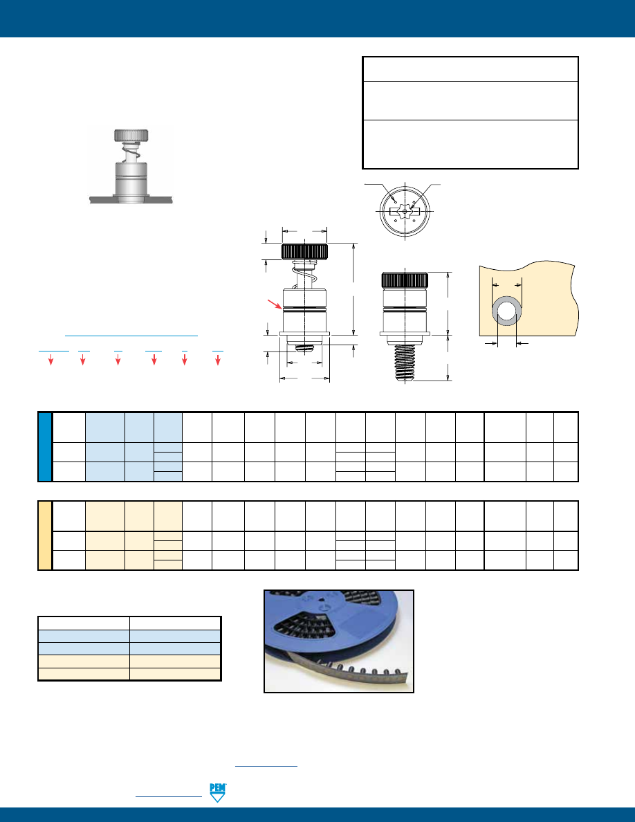
PF-24
PennEngineering •
www.pemnet.com
REELFAST® SMTPFLSM™ SURFACE MOUNT CAPTIVE PANEL SCREWS
All dimensions are in inches.
U
NIF
IE
D
Screw A Min.
ØK Hole Size ØD Min.
Thread
Thread Length (Shank) Sheet
C
E
1
E
2
G
1
G
2
H T
1
T
2
in Sheet
Solder Driver
Size
Type
Code Code Max. Thickness
Max.
±.010
Nom
±.025
±.025
±.010
Nom.
Nom.
+.003 -.000
Pad
Size
.112-40
SMTPFLSM 440 0 .063 .063 .215 .280 .300 .040 .210 .100 .38 .55
.220 .340 T15
(#4-40)
1 .100
.270
.138-32
SMTPFLSM 632 0 .063 .063 .247 .310 .320 .040 .240 .100 .42 .62
.252 .400 T15
(#6-32)
1 .100
.300
All dimensions are in millimeters.
ME
TR
IC
Screw A Min.
ØK Hole Size ØD Min.
Thread
Thread Length (Shank) Sheet
C
E
1
E
2
G
1
G
2
H T
1
T
2
in Sheet
Solder Driver
Size
Type
Code Code Max. Thickness Max. ±0.25 Nom ±0.64 ±0.64 ±0.25 Nom. Nom. +0.08 Pad Size
M3 x 0.5
SMTPFLSM
M3
0 1.6 1.6 5.46 7 7.6 1 5.3 2.5 9.6 14 5.6 8.6 T15
1 2.5
6.8
M3.5 x 0.6
SMTPFLSM
M3.5
0 1.6 1.6 6.27 7.9 8.13 1 6.1 2.5 10.7 15.7 6.4 10.2 T15
1 2.5
7.62
Ø
H
Ø
D
Solder
Pad
Plated through hole
not required.
SMTPF LS
M – 440 – 0
ET
Type
PART NUMBER DESIGNATION
Thread
Code
Driver
Anti-cross
Thread
Feature
Length
Code
Finish
NUMBER OF PARTS PER REEL
Thread Size
Parts Per Reel
440
200
632
150
M3
200
M3.5
150
Packaged on 330 mm recyclable reels. Tape width is 24 mm.
Supplied with polyimide patch for vacuum pick up. Reels conform to EIA-481.
•
All metal captive screw assembly installs in one piece
utilizing pick and place method.
•
Combination drive, Torx®/slot.
•
Solderable finish.
Threads:
External, ASME B1.1, 2A / ASME B1.13M, 6g
(1)
Material:
Retainer: Carbon Steel
Screw: Hardened Carbon Steel
Spring: 300 Series Stainless Steel
Finish
:
Retainer: ET - Electro-plated tin ASTM B545, Class B
with preservative coating, annealed
(2)
Screw: ZI - Zinc plated, 5µm, colorless
(3)
Spring: Natural Finish
(1) As with all Class 2A/6g external threads with an additive finish, the maximum major and pitch, after plating, may equal basic sizes and be gauged to
Class 3A/4h, per ANSI B1.1, Section 8, Table 3A and ANSI B1.13M, Section 8, Paragraph 8.2
(2) Optimal solderability life noted on packaging.
(3) See PEM Technical Support section of our website (
www.pemnet.com
) for related plating standards and specifications.
Installation Data page 36. Performance Data page 41.
E
1
H
C
A
E
2
T
2
T
1
G
1
G
2
Dimples on head
designate metric thread.
Torx®/slot driver size.
(See chart)
Two Groove
(Registered
Trademark)
pem-html.html
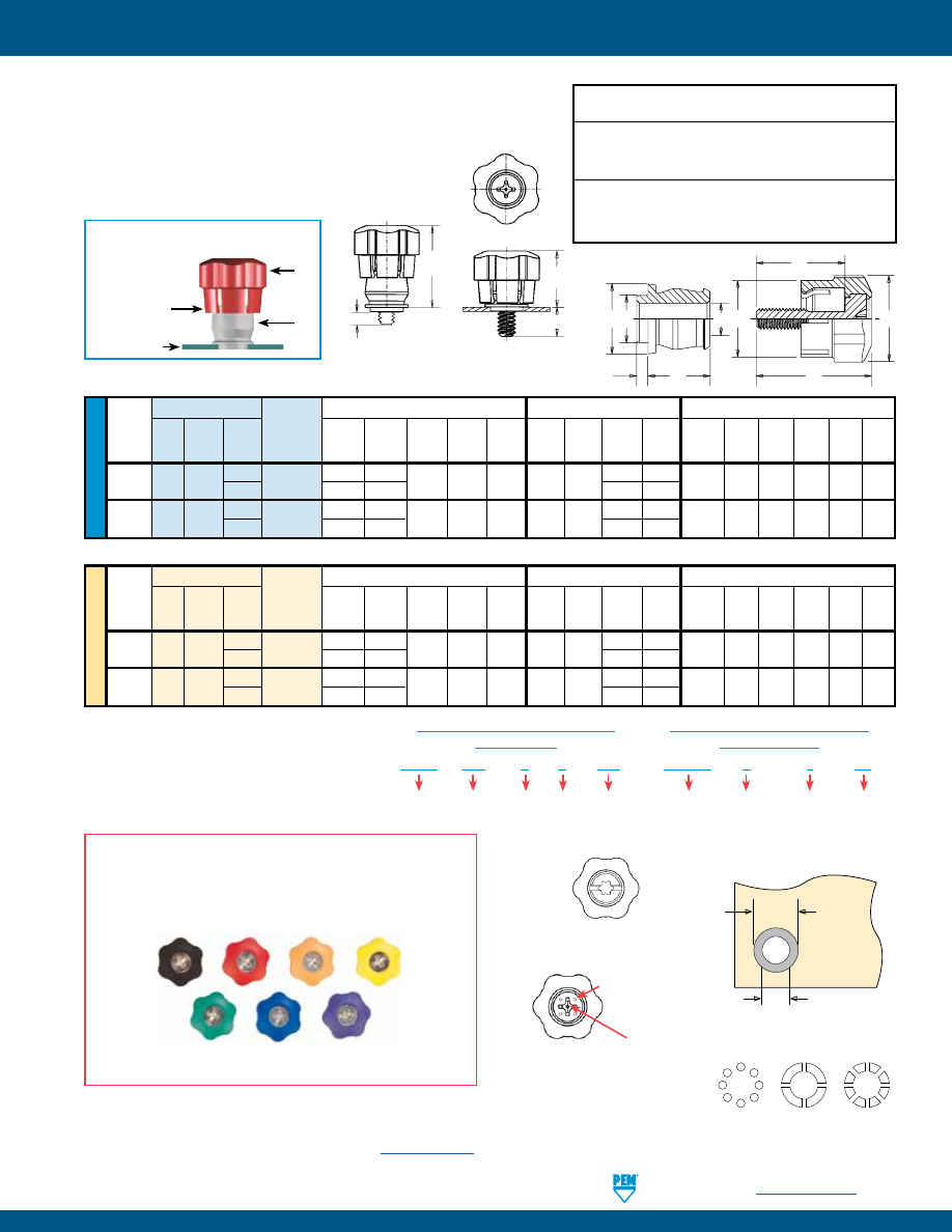
PennEngineering •
www.pemnet.com
PF-25
REELFAST® SMTPF™ SURFACE MOUNT CAPTIVE PANEL SCREWS
Threads:
External, ASME B1.1, 2A / ASME B1.13M, 6g
(1)
Material:
Knob: ABS
(2)
Retainer: Carbon Steel
Screw: Carbon Steel
Finish
:
Retainer: ET - Electro-plated tin ASTM B545, Class B
with preservative coating, annealed
Screw: CN - Bright nickel over copper flash per ASTM B689
•
Retainer installed using conventional surface mount
techniques.
•
Simply snap screw into retainer to complete assembly.
•
Black ABS knob standard.
•
Optional molded-through colors available.
•
Available with Torx® recess.
U
NIF
IE
D
Available with Torx®
recess on special order.
Stencil Masking Examples
SMTPR – 6 – 1
ET
Type
PART NUMBER DESIGNATION
FOR RETAINER
Finish
Retainer
Size
Shank
Code
PSHP – 632 – 0
L
001
Type
PART NUMBER DESIGNATION
FOR SCREW
Cap
Style
(Lobed)
Thread
Code
Length
Code
Color
Code
(Standard
Black)
Screw Part Number
Assembly Dimensions
Screw Dimensions
Retainer Dimensions
Screw
Retainer
Total A
Min.
Thread
Thread Length
Part
G
P
T
1
T
2
Radial C
1
E
1
L
T (Shank) Sheet B
C
E R
Size
Type
Code
Code
Number
± .025
± .025
Nom.
Nom.
Float
±.010
±.010
±.015
Nom.
Max.
Thick. ±.003
Max. Nom. ±.005
.112-40
PSHP 440
0
SMTPR-6-1
.188 .000
.478 .646 .015 .440 .542
.510 .663
.060 .060 .167 .249 .375 .325
(#4-40)
1 .248
.026
.570
.723
.138-32
PSHP 632
0
SMTPR-6-1
.188 .000
.478 .646 .020 .440 .542
.510 .663
.060 .060 .167 .249 .375 .325
(#6-32)
1 .248
.026
.570
.723
All dimensions are in inches.
All dimensions are in millimeters.
ME
TR
IC
Screw Part Number
Assembly Dimensions
Screw Dimensions
Retainer Dimensions
Thread
Screw
Retainer
Total A
Min.
Size x
Thread Length
Part
G
P
T
1
T
2
Radial C
1
E
1
L
T (Shank) Sheet B
C
E R
Pitch
Type
Code
Code
Number
± 0.64
± 0.64
Nom.
Nom.
Float
±0.25 ±0.25
±0.38
Nom.
Max.
Thick. ±0.08
Max. Nom. ±0.13
M3 x 0.5 PSHP
M3
0
SMTPR-6-1
4.78 0
12.14 16.41 .38 11.18 13.77
12.95 16.84
1.53 1.53 4.24 6.33 9.53 8.26
1 6.3
.66
14.48
18.36
M3.5 x 0.6 PSHP M3.5
0
SMTPR-6-1
4.78 0
12.14 16.41 .51 11.18 13.77
12.95 16.84
1.53 1.53 4.24 6.33 9.53 8.26
1 6.3
.66
14.48
18.36
RETAINER -
Packaged on 330 mm recyclable reels of 465
pieces. Tape width is 24 mm. Supplied with Kapton® patch for
vacuum pick up. Reels conform to EIA-481.
SCREW -
Packaged in bags. Retainers and screws are sold
separately.
.396”/
10.06 mm
Min.
Solder
Pad
Plated through hole
not required.
.250”
+.003 –.000
6.35 mm
+0.08
Four dimples on
head designate
metric thread.
Metal Phillips Recess
#4-40 & M3 = #1
#6-32 & M3.5 = #2
When Assembled
Spring action of
plastic “fingers”
holds screw
in retracted
position.
PSHP
SMTPR
PC Board
R
E
A
C
B
E
1
L
T
C
1
T
2
T
1
G
P
Patented.
The colors shown here (codes #002 thru #007) are non-stocked standards and
available on special order. Since actual cap colors may vary slightly from those
shown here, we recommend that you request samples for color verification. If you
require a custom color or you need a “color matched” cap, please contact us.
Std. Black #001 Red #002 Orange #003 Yellow #004
Green #005
Blue #006
Violet #007
Non-flammable UL 94-V0 plastic caps are available on special order.
COLOR CAPABILITIES FOR PSHP SCREW
(1) As with all Class 2A/6g external threads with an additive finish, the maximum major
and pitch, after plating, may equal basic sizes and be gauged to Class 3A/4h, per ANSI
B1.1, Section 8, Table 3A and ANSI B1.13M, Section 8, Paragraph 8.2.
(2) See PEM Technical Support section of our website (
www.pemnet.com
) for related
plating standards and specifications.
Installation Data page 36.
Performance Data page 41.
pem-html.html
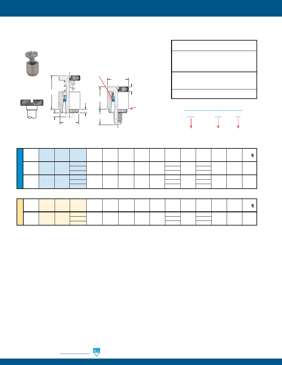
PF-26
PennEngineering •
www.pemnet.com
PFK™ BROACHING CAPTIVE PANEL SCREWS
ME
TR
IC
U
NIF
IE
D
Thread Thread
Screw
A
Min.
Hole Size
C
E
G H P T
1
T
2
Min. Dist.
Size Type Code
Length (Shank)
Sheet
In Sheet
± .003
±.010
± .016
± .005
± .025
Max.
Nom. Hole
C/L
Code
Max.
Thickness
+.003
-.000
To
Edge
.112-40 40 .250 .000
(#4-40)
PFK 440 62 .060 .060 .265 .283 .312 .375 .072 .125 .36 .54 .20
84 .500 .250
.138-32 40 .250 .000
(#6-32)
PFK 632 62 .060 .060 .281 .299 .344 .375 .072 .125 .36 .54 .26
84 .500 .250
Thread
Thread
Screw
A
Min.
Hole Size
C
E
G H P T
1
T
2
Min. Dist.
Size x
Type
Code
Length (Shank)
Sheet
In Sheet
± 0.08
±.25
± 0.4
± 0.13
± 0.64
Max.
Nom. Hole
C/L
Pitch
Code
Max.
Thickness
+0.08
To
Edge
40 6.4 0
M3 x 0.5
PFK
M3
62
1.53
1.53
6.73
7.19
7.92
9.5
1.83
3.2
9.14
13.72
5.08
84 12.7 6.4
PFK – 632 – 40
PART NUMBER DESIGNATION
Type
Thread Size
Code
Screw
Length
Code
All dimensions are in inches.
All dimensions are in millimeters.
Threads:
External, ASME B1.1, 2A / ASME B1.13M, 6g
Material:
Retainer: 300 Series Stainless Steel
Screw: 300 Series Stainless Steel
Spring: 300 Series Stainless Steel
Retaining Ring: Nylon, temperature limit 200˚ F / 93˚ C
Finish
:
Retainer: Passivated and/or tested per ASTM A380
Screw: Passivated and/or tested per ASTM A380
Spring: Natural Finish
For use in:
PC Boards
•
For permanent and reliable installation in PC boards.
•
Screw assemblies remain captive for easy mounting and removal.
Installation Data page 33. Performance Data page 41.
Diagonal knurl
identifies metric
thread sizes
T
2
T
1
P
C
A
G
H
E
Shoulder
provides
positive
stop during
installation.
Blue plastic retaining ring*
(Trademark)
pem-html.html
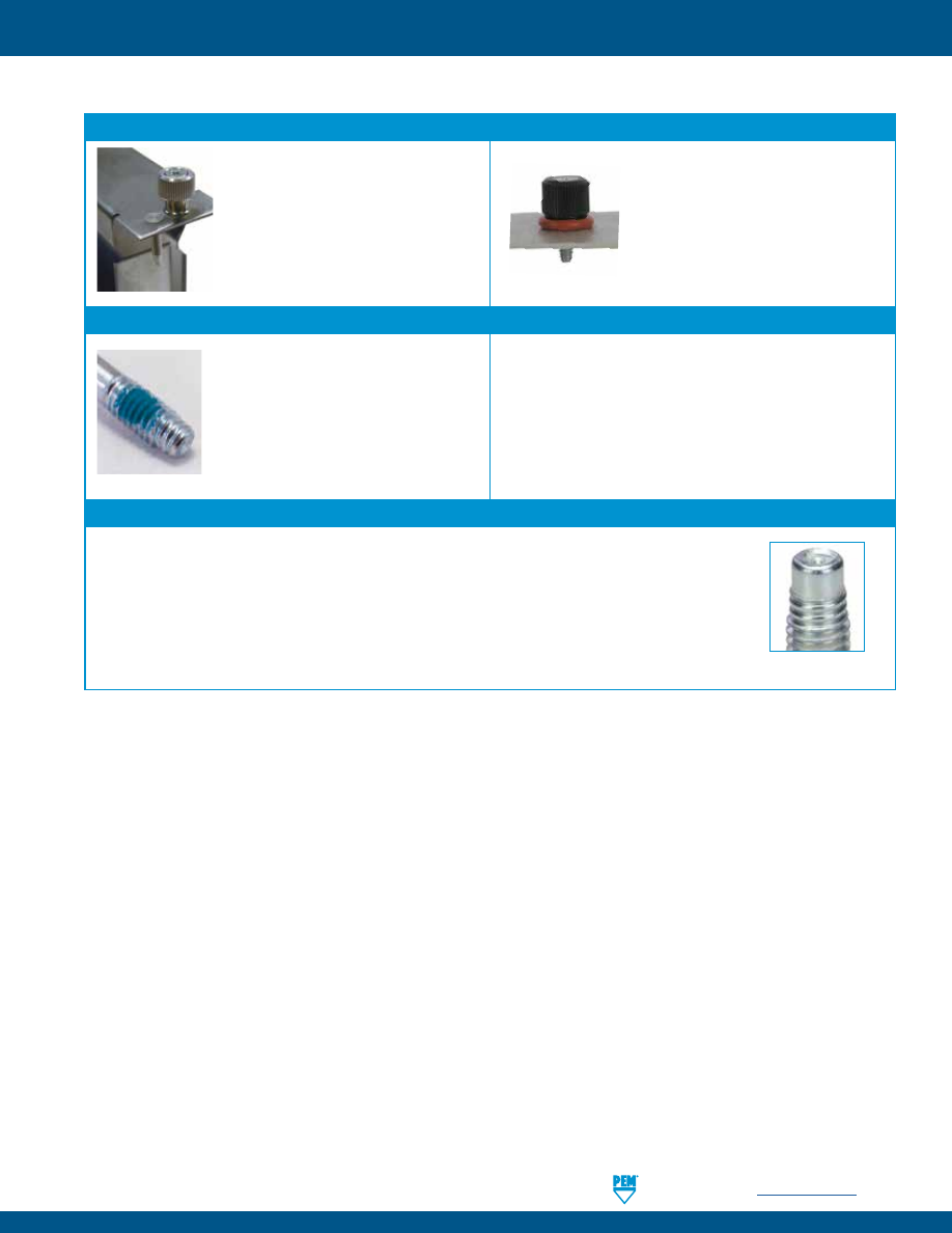
PennEngineering •
www.pemnet.com
PF-27
VALUE-ADDED CAPABILITIES
VALUE-ADDED CAPABILITIES
ATCA Solutions
Use PF11PM captive panel screw and
TPXS pin in conjunction to satisfy the
requirements of the PICMG 3.0 of the
Advanced TCA®.
Consider adding an o-ring to our PEM
C.A.P.S.® captive panel screw. When
fastened, it provides a tight seal above
the panel.
Tight Seal Solutions
Nylon Locking Patch
Thread-forming Opportunity
Nylon locking patch is available to be added
to any of PEM captive panel screws for
applications requiring a locking element.
PennEngineering is official licensee for REMFORM®, TAPTITE®, PT®,
and DELTA PT® fastener products.
REMFORM® and TAPTITE® are trademarks of REMINC®.
PT® and DELTA PT® are trademarks of EJOT®.
MAThread® Anti Cross-thread Technology
PennEngineering is a licensee of MAThread® Anti Cross-Threading Technology. This unique design allows the threads
to self-align and drive easily with reduced effort. This helps speed assembly, reduce or eliminate failures, repairs,
scrap, downtime, and warranty service associated with thread damage. This option is available on most types of
PEM captive panel screws.
MAThread® is a registered trademark of MAThread inc.
Anti Cross-Thread Feature
pem-html.html
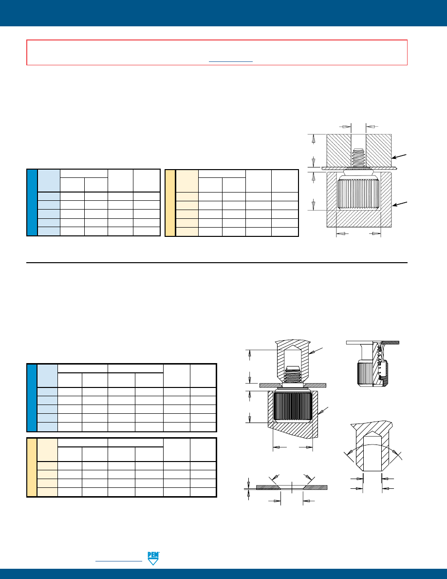
PF-28
PennEngineering •
www.pemnet.com
CAPTIVE PANEL SCREW INSTALLATION
ME
TR
IC
U
NIF
IE
D
Anvil Dimensions (in.)
Thread
A C
Anvil Part
Punch Part
Code
±.002 ±.002 Number Number
440 .260 .437 8003521 8003518
632
.390
.468
8003522 8003519
832
.390
.531
8003523 8003520
032
.390
.531
8003523 8004350
0420
.480
.598
8004351 8004352
Anvil Dimensions (mm)
Thread
A C
Anvil Part
Punch Part
Code
±0.05 ±0.05 Number Number
M3 6.6 11.1 8003521 8003518
M3.5
9.91
11.89
8003522 8003519
M4
9.91
13.49 8003523 8003520
M5
9.91
13.49 8003523 8004350
M6
12.19
15.19 8004351 8004352
PEMSERTER® Installation Tooling
(1)
Max. Screw
Extension
PUNCH
ANVIL
A
C
Thread Dia. +.080” / +2 mm
PF11™/PF12™/PF11M™/PF12M™/PEM C.A.P.S.® FASTENERS
1.
Prepare properly sized mounting hole in sheet. Do not perform any secondary
operations such as deburring.
2.
Place fastener into recessed anvil, and place workpiece (preferably the punch
side) over shank of fastener.
3.
With installation punch and anvil surfaces parallel, apply squeezing force until the
shoulder of the retainer comes in contact with the sheet material.
(1) Punches and anvils should be hardened.
U
NIF
IE
D
PF11MF™/PF12MF™ FASTENERS
(flare-mount installation)
1.
Prepare properly sized mounting hole in sheet with countersink.
2.
Place fastener into recessed anvil, and place workpiece over shank
of fastener.
3.
With installation punch and anvil surfaces parallel, apply
squeezing force to flare the retainer of the fastener.
Anvil Dimensions (in.)
Punch Dimensions (in.)
Thread A C
E
F Anvil Punch
Code
±.002
±.002
+.003 –.000
±.002
Part No.
Part No.
440
.260
.437
.123
.133
8003521
8013670
632
.390
.468
.143
.156
8003522
8013671
832
.390
.531
.202
.210
8003523 8013672
032
.390
.531
.202
.210
8003523 8013672
0420
.480
.598
.255
.264
8004351
8013674
PEMSERTER® Installation Tooling
(1)
ME
TR
IC
Anvil Dimensions (mm)
Punch Dimensions (mm)
Thread A
C
E
F Anvil Punch
Code
±0.05 ±0.05
+0.08 ±0.05
Part No.
Part No.
M3
6.6
11.1
3.12
3.38
8003521 8013670
M4
9.91
13.49
5.13
5.33
8003523 8013672
M5
9.91
13.49
5.13
5.33
8003523 8013672
M6
12.19
15.19
6.48
6.71
8004351 8013674
E
F
.015” ±.005”
0.38mm ±0.1mm
90˚
Nom.
C
A
90˚
Nom.
.500” / 12.7mm
Min.
PUNCH
ANVIL
PUNCH DETAIL
COUNTERSINK DETAIL
AFTER INSTALLATION
BEFORE INSTALLATION
Mounting Hole Dia.
(see page 6)
(1) Punches and anvils should be hardened.
INSTALLATION NOTES
•
For best results we recommend using a PEMSERTER® press for installation of PEM self-clinching fasteners. Please check our website for more information.
•
Visit the Animation Library on our website to view the installation process
for select products
.
pem-html.html
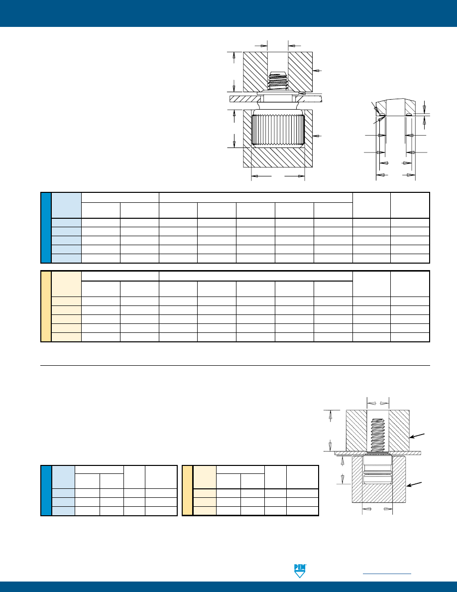
PennEngineering •
www.pemnet.com
PF-29
CAPTIVE PANEL SCREW INSTALLATION
PF11MW™/PF12MW™ FASTENERS
1.
Prepare properly sized mounting hole in sheet.
2.
Place fastener into recessed anvil, place
workpiece over shank of fastener, then place the
washer over the shank of the fastener.
3.
With installation punch and anvil surfaces
parallel, apply squeezing force with flaring punch.
PEMSERTER® Installation Tooling
(1)
U
NIF
IE
D
Anvil Dimensions (in.)
Punch Dimensions (in.)
Thread A
C
E
F
G
H
I
Anvil
Punch
Code
±.002 ±.001
+.003 –.000 ±.001
±.003
Min.
±.004
Part No.
Part No.
440
.260
.437
.120
.135
.204
.250
.015
8003521
8014304
632
.390
.468
.140
.159
.249
.300
.015
8003522
8014305
832
.390
.531
.201
.217
.340
.400
.028
8003523
8014306
032
.390
.531
.201
.217
.340
.400
.028
8003523
8014306
0420
.480
.598
.252
.271
.430
.500
.028
8004351
8014307
ME
TR
IC
Anvil Dimensions (mm)
Punch Dimensions (mm)
Thread A
C
E
F
G
H
I
Anvil
Punch
Code
±0.05 ±0.03
+0.08 ±0.03
±0.08
Min.
±0.1
Part No.
Part No.
M3
6.6
11.1
3.05
3.43
5.18
6.35
.381
8003521
8014304
M3.5
9.9
11.9
3.56
4.04
6.32
7.62
.381
8003522
8014305
M4
9.9 13.5 5.11 5.51 8.64 10.16 .711
8003523
8014306
M5
9.9 13.5 5.11 5.51 8.64 10.16 .711
8003523
8014306
M6
12.2
15.2
6.4
6.88
10.92
12.7
.711
8004351
8014307
H
E
F
FLARING PUNCH DETAIL
G
I
.010” R /
0.254mm R
Max.
.003” R /
0.08mm R
Max.
C
A
WASHER
E
ANVIL
PUNCH
PANEL
Max. Screw
Extension
ME
TR
IC
U
NIF
IE
D
Anvil Dimensions (in.)
Thread
A C
Anvil Part
Punch Part
Code
±.002 ±.002 Number Number
440
.220
.285 8004688 970200009400
632
.250
.301 8004689 8015656
832
.285
.332 8005439 970200230400
Anvil Dimensions (mm)
Thread
A C
Anvil Part
Punch Part
Code
±0.05 ±0.05 Number Number
M3
5.59
7.24 8004688 970200020400
M3.5
6.35
7.65 8004689 8015656
M4
7.24
8.43 8005439 970200230400
PFHV™ FASTENERS
1.
Prepare properly sized mounting hole in sheet. Do not perform any secondary
operations such as deburring.
2.
Place fastener into recessed anvil, and place workpiece (preferably the punch
side) over shank of fastener.
3.
With installation punch and anvil surfaces parallel, apply squeezing force until
the shoulder of the retainer comes in contact with the sheet material.
PEMSERTER® Installation Tooling
(1)
PUNCH
ANVIL
A
C
Thread Dia. +.080” / +2 mm
Max. Screw
Extension
(1) Punches and anvils should be hardened.
(1) Punches and anvils should be hardened.
pem-html.html
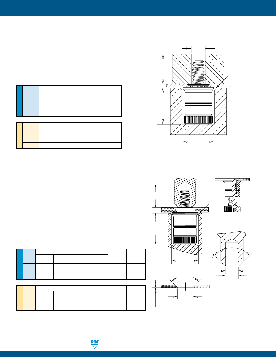
PF-30
PennEngineering •
www.pemnet.com
CAPTIVE PANEL SCREW INSTALLATION
U
NIF
IE
D
PF7M™ FASTENERS
1.
Prepare properly sized mounting hole in sheet. Do not
perform any secondary operations such as deburring.
2.
Place fastener into recessed anvil, and place workpiece
(preferably the punch side) over the shank of fastener.
3.
With installation punch and anvil surfaces parallel, apply
squeezing force until the shoulder of the retainer comes in
contact with the sheet material.
Thread
Anvil Dimensions (in.)
Anvil Punch
Code
A
C
Part Part
±.002 ±.002 Number Number
440 .319 .290 8016175 8003518
632
.333
.330
8016176
8003519
832
.353
.385
8016177
8003520
ME
TR
IC
Thread
Anvil Dimensions (mm)
Anvil Punch
Code
A
C
Part Part
±0.05 ±0.05 Number Number
M3 8.1 7.34 8016175 8003518
M4
8.9
9.8
8016177
8003520
A
C
Thread Dia.
+.080” / +2mm
.020” / .51 mm x
45˚ Nom.
Max. Screw
Extension
PUNCH
ANVIL
PF7MF™ FASTENERS
(flare-mount installation)
1.
Prepare properly sized mounting hole in sheet with
countersink. Do not perform any secondary operations
such as deburring.
2.
Place fastener into recessed anvil, and place workpiece
over the shank of fastener.
3.
With installation punch and anvil surfaces parallel, apply
squeezing force to flare the retainer of the fastener.
U
NIF
IE
D
Anvil Dimensions (in.)
Punch Dimensions (in.)
Thread A
C
E
F Anvil Punch
Code
±.002
±.002
+.003 –.000
±.002
Part No.
Part No.
440
.319
.290
.123
.133
8016175
8013670
632
.333
.330
.143
.156
8016176
8013671
832
.353
.385
.202
.210
8016177
8013672
ME
TR
IC
Anvil Dimensions (mm)
Punch Dimensions (mm)
Thread A
C
E
F Anvil Punch
Code
±0.05 ±0.05
+0.08 ±0.05
Part No.
Part No.
M3
8.1
7.34
3.12
3.38
8016175
8013670
M4
8.9
9.8
5.13
5.33
8016177
8013672
90˚ Nom.
ANVIL
A
C
E
PUNCH
.020” / .51mm x
45˚ Nom.
Max. Screw
Extension
90˚ Nom.
COUNTERSINK DETAIL
.015” ±.005”
0.38 mm ±0.1mm
F
PUNCH DETAIL
Mounting Hole Dia.
(see page 11)
AFTER INSTALLATION
BEFORE INSTALLATION
PEMSERTER® Installation Tooling
(1)
PEMSERTER® Installation Tooling
(1)
(1) Punches and anvils should be hardened.
(1) Punches and anvils should be hardened.
pem-html.html
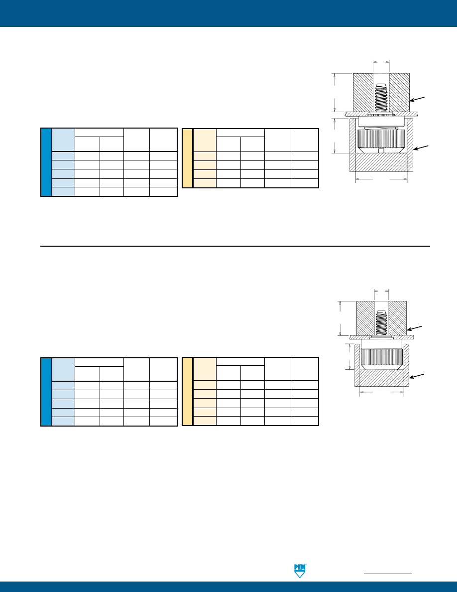
PennEngineering •
www.pemnet.com
PF-31
CAPTIVE PANEL SCREW INSTALLATION
ME
TR
IC
U
NIF
IE
D
Anvil Dimensions (in.)
Thread
A C
Anvil Part
Punch Part
Code
±.002 ±.002 Number Number
440 .295 .421 975201060 975200060
632
.295
.453 975201061 975200061
832
.310
.484 975201062 975200062
032
.310
.546 975201063 975200063
0420
.365
.640 975201064 975200064
Anvil Dimensions (mm)
Thread
A C
Anvil Part
Punch Part
Code
±0.05 ±0.05 Number Number
M3
7.49
10.69 975201060 975200060
M3.5
7.49
11.51
975201061 975200061
M4
7.87
12.29 975201062 975200062
M5
7.87
13.87 975201063 975200063
M6
9.27
16.26 975201064 975200064
PF50™/PF51™/PF52™/PF60™/PF61™/PF62™ FASTENERS
1.
Prepare properly sized mounting hole in sheet. Do not perform any secondary
operations such as deburring.
2.
Place fastener into recessed anvil, and place workpiece (preferably the punch side)
over shank of fastener.
3.
With installation punch and anvil surfaces parallel, apply squeezing force until the
shoulder of the retainer comes in contact with the sheet material.
PEMSERTER® Installation Tooling
(1)
PUNCH
ANVIL
A
C
Thread Dia. +.080” / +2mm
Max. Screw
Extension
ME
TR
IC
U
NIF
IE
D
Anvil Dimensions (in.)
Thread
A C
Anvil Part
Punch Part
Code
±.002 ±.002 Number Number
440 .295 .421 975201060 975200060
632
.295
.453 975201061 975200061
832
.310
.484 975201062 975200062
032
.310
.546 975201063 975200063
0420
.365
.640 975201064 975200064
Anvil Dimensions (mm)
Thread
A C
Anvil Part
Punch Part
Code
±0.05 ±0.05 Number Number
M3
7.49
10.69 975201060 975200060
M4
7.87
12.29 975201062 975200062
M5
7.87
13.87 975201063 975200063
M6
9.27
16.26 975201064 975200064
PEMSERTER® Installation Tooling
(1)
PF30™/PF31™/PF32™ FASTENERS
1.
Prepare properly sized mounting hole in sheet. Do not perform any secondary
operations such as deburring.
2.
Place fastener into recessed anvil, and place workpiece (preferably the punch side)
over shank of fastener.
3.
With installation punch and anvil surfaces parallel, apply squeezing force until the
shoulder of the retainer comes in contact with the sheet material.
PUNCH
ANVIL
A
C
Thread Dia. +.080” / +2mm
Max. Screw
Extension
(1) Punches and anvils should be hardened.
(1) Punches and anvils should be hardened.
pem-html.html
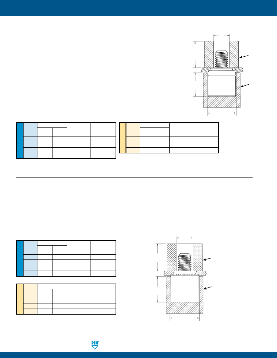
PF-32
PennEngineering •
www.pemnet.com
CAPTIVE PANEL SCREW INSTALLATION
ME
TR
IC
U
NIF
IE
D
Anvil Dimensions (in.)
Thread
A C
Anvil Part
Punch Part
Code
±.002 ±.002 Number Number
440 .345 .323 975200026 975200060
632
.345
.358
975200027
975200061
832
.435
.386
975200028
975200062
032
.435
.421
975200029
9752000063
Anvil Dimensions (mm)
Thread
A C
Anvil Part
Punch Part
Code
±0.05 ±0.05 Number Number
M3 8.76 8.2 975200026 9752000060
M4
11.05
9.8
975200028
9752000062
M5
11.05
10.69
975200029
9752000063
PFC2P™ FASTENERS
1.
Prepare properly sized mounting hole in sheet. Do not perform any secondary operations such as deburring.
2.
Place fastener into recessed anvil, and place workpiece (preferably the punch side) over shank of fastener.
3.
With installation punch and anvil surfaces parallel, apply squeezing force until the shoulder of the retainer comes in
contact with the sheet material.
PEMSERTER® Installation Tooling
(1)
ME
TR
IC
U
NIF
IE
D
Anvil Dimensions (in.)
Thread
A C
Anvil Part
Punch Part
Code
±.002 ±.002 Number Number
440 .345 .358 975200027 975200060
632
.345
.390
975201243
975200061
832
.435
.421
975200029
975200062
032
.435
.452
975201244
975200063
Anvil Dimensions (mm)
Thread
A C
Anvil Part
Punch Part
Code
±0.05 ±0.05 Number Number
M3 8.76 9.09 975200027 975200060
M4
11.05
10.69
975200029
975200062
M5
11.05
11.48
975201244
975200063
PFC4™ FASTENERS
1.
Prepare properly sized mounting hole in sheet. Do not perform any secondary
operations such as deburring.
2.
Place fastener into recessed anvil, and place workpiece (preferably the punch side)
over shank of fastener.
3.
With installation punch and anvil surfaces parallel, apply squeezing force until the
shoulder of the retainer comes in contact with the sheet material.
Installation Requirements
1.
Sheet hardness must be less than 88 on the Rockwell “B” scale.
2.
Hole punch should be kept sharp to minimize work hardening around hole.
3.
Fastener should be installed in punch side of hole.
4.
Fastener should not be installed near bends or other highly cold worked areas
where sheet hardness may be greater than 88 on the Rockwell “B” scale.
PEMSERTER® Installation Tooling
(1)
PUNCH
ANVIL
A
C
Thread Dia. +.080” / +2mm
Max. Screw
Extension
PUNCH
ANVIL
A
C
Thread Dia. +.080” / +2mm
Max. Screw
Extension
(1) Punches and anvils should be hardened.
(1) Punches and anvils should be hardened.
pem-html.html
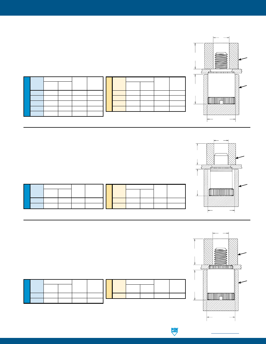
PennEngineering •
www.pemnet.com
PF-33
CAPTIVE PANEL SCREW INSTALLATION
ME
TR
IC
U
NIF
IE
D
Anvil Dimensions (in.)
Thread
A C
Anvil Part
Punch Part
Code
±.002 ±.002 Number Number
440 .345 .323 975200026 975200060
632
.345
.358 975200027 975200061
832
.435
.386 975200028 975200062
032
.435
.421 975200029 975200063
0420
.565
.484 975200030 975200064
Anvil Dimensions (mm)
Thread
A C
Anvil Part
Punch Part
Code
±0.05 ±0.05 Number Number
M3
8.76
8.2 975200026 975200060
M4
11.05
9.8 975200028 975200062
M5
11.05
10.69 975200029 975200063
M6
14.35
12.29 975200030 975200064
PEMSERTER® Installation Tooling
(1)
PFC2™/PFS2™ FASTENERS
1.
Prepare properly sized mounting hole in sheet. Do not perform any secondary
operations such as deburring.
2.
Place fastener into recessed anvil, and place workpiece (preferably the punch
side) over shank of fastener.
3.
With installation punch and anvil surfaces parallel, apply squeezing force until
the shoulder of the retainer comes in contact with the sheet material.
PUNCH
ANVIL
A
C
Thread Dia. +.080” / +2mm
Max. Screw
Extension
ME
TR
IC
U
NIF
IE
D
Anvil Dimensions (in.)
Type
A C
Anvil Part
Punch Part
±.002 ±.002 Number Number
PTL2
.580
.520 975201245 970200013300
PSL2
.490
.520 8021146 970200013300
Anvil Dimensions (mm)
Type
A C
Anvil Part
Punch Part
±0.05 ±0.05 Number Number
PTL2
14.86
13.21 975201245 970200013300
PSL2
12.47
13.21 8021146 970200013300
PEMSERTER® Installation Tooling
(1)
PTL2™/PSL2™ FASTENERS
1.
Prepare properly sized mounting hole in sheet. Do not perform any secondary
operations such as deburring.
2.
Place fastener into recessed anvil, and place workpiece (preferably the punch side)
over shank of fastener.
3.
With installation punch and anvil surfaces parallel, apply squeezing force until the
shoulder of the retainer comes in contact with the sheet material.
PUNCH
ANVIL
A
C
Pin Dia. +.080” / +2mm
Max. Pin
Extension
ME
TR
IC
U
NIF
IE
D
Anvil Dimensions (in.)
Thread
A C
Anvil Part
Punch Part
Code
±.002 ±.002 Number Number
440 .320 .323 975200026 975200060
632
.320
.358 975200027 975200061
Anvil Dimensions (mm)
Thread
A C
Anvil Part
Punch Part
Code
±0.05 ±0.05 Number Number
M3
8.13
8.2 975200026 975200060
PFK™ FASTENERS
1.
Prepare properly sized mounting hole in board.
2.
Place fastener into recessed anvil, and place workpiece over shank of fastener.
3.
With installation punch and anvil surfaces parallel, apply squeezing force until
the shoulder of the retainer comes in contact with the board.
PEMSERTER® Installation Tooling
(1)
PUNCH
ANVIL
A
C
Thread Dia. +.080” / +2mm
Max. Screw
Extension
(1) Punches and anvils should be hardened.
(1) Punches and anvils should be hardened.
(1) Punches and anvils should be hardened.
pem-html.html
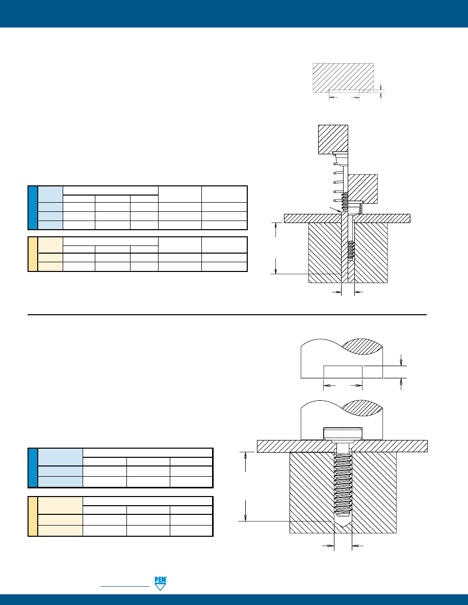
PF-34
PennEngineering •
www.pemnet.com
CAPTIVE PANEL SCREW INSTALLATION
ME
TR
IC
U
NIF
IE
D
SCB™/SCBJ™ FASTENERS
1.
Prepare properly sized mounting hole in sheet.
2.
Place the fastener through mounting hole and into anvil. A flat or
recessed punch can be used.
3.
With installation punch and anvil surfaces parallel, apply squeezing
force to the top of the screw head and the underside of the sheet
material. The squeezing action forces the shoulder of the screw
into the sheet, displacing sheet material, causing it to fill the void
under the head and shoulder of the screw.
Thread
Installation Tooling Dimensions (in.)
Code C E H
440
.113 - .116
.270 - .280
.073 - .074
632
.139 - .142
.308 - .318
.073 - .074
Thread
Installation Tooling Dimensions (mm)
Code C E H
M3
3.03 - 3.11
6.86 - 7.11
1.85 - 1.88
M4
4.03 - 4.11
8.53 - 8.79
1.85 - 1.88
E
H
L*
+.125” / 3.18mm
Min.
C
PEMSERTER® Installation Tooling
(1)
U
NIF
IE
D
Thread Installation Tooling Dimensions (in.)
Anvil
Magnetic Punch
Code
C J K
Part Number
Part Number
(2)
440
.113 - .116
.354 – .357
.035
970200048300
8016210
632
.139 - .142
.387 – .390
.035
970200052300
8016211
832
.165 - .168
.416 – .419
.035
970200054300
8016212
ME
TR
IC
Thread Installation Tooling Dimensions (mm)
Anvil
Magnetic Punch
Code
C J K
Part Number
Part Number
(2)
M3
3.03 - 3.11
9.25 – 9.32
0.89
970200049300
8016213
M4
4.03 - 4.11
10.8 – 10.9
0.89
970200053300
8016214
(1) Punches and anvils should be hardened.
(2) Pneumatic punch may also be used. Please contact our PEMSERTER tooling
division for punch part numbers.
SCBR™ FASTENERS
1.
Prepare properly sized mounting hole in sheet.
Do not perform any
secondary operations such as deburring. If the hole is punched, be
sure to install fastener into punched side of hole.
2.
Assemble spring on screw by rotating spring counter clockwise
and position assembly into recessed magnetic punch.
3.
Position hole in workpiece over retractable anvil pin.
4.
With installation punch and anvil surfaces parallel, apply squeezing
force on top of the screw head and the underside of the sheet
material. The squeezing action forces the displacer of the screw
into the sheet, causing it to reduce the mounting hole diameter and
captivate the screw.
K
J
Magnetic
Punch
(1)
BEFORE
AFTER
SHEET
ANVIL
ANVIL PIN
L*
+.125” / 3.18mm
Min.
C
Magnetic
Punch
(1)
Magnetic
Punch
(1)
PEMSERTER® Installation Tooling
(1)
* For “L”,
see page 18.
* For “L”,
see page 19.
(1) Punches and anvils should be hardened.
pem-html.html
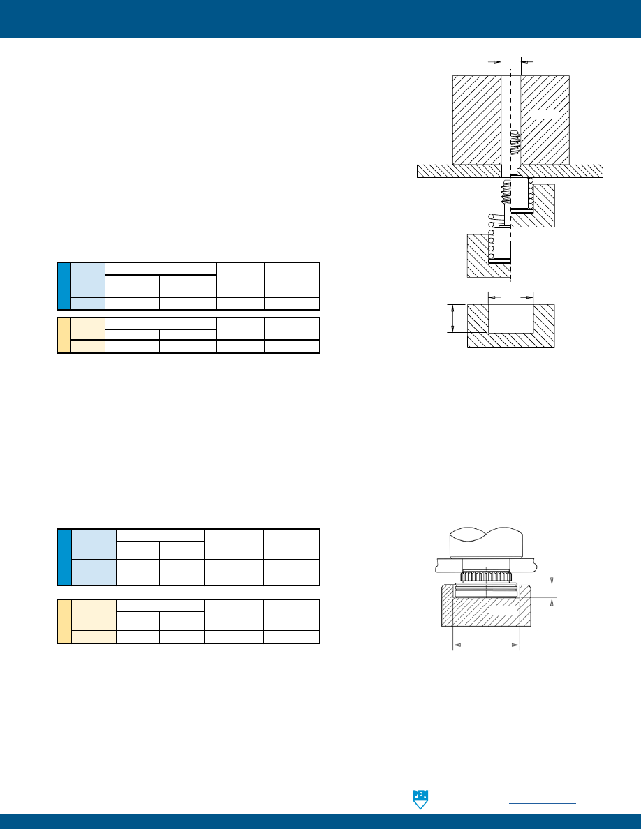
PennEngineering •
www.pemnet.com
PF-35
CAPTIVE PANEL SCREW INSTALLATION
U
NIF
IE
D
ME
TR
IC
HSCB™ FASTENER INTO HEAT SINK
1.
Prepare properly sized mounting hole in heat sink. Do not perform any
secondary operations such as deburring. If the hole is punched, be sure to
install the fastener into the punch side of the hole.
2.
Place the head of the screw into the recess of the installation anvil
and position assembly into recessed magnetic punch.
3.
Place the spring over the shoulder of the screw, maintaining concentricity.
4.
Position the heat sink mounting hole over the screw.
5.
Bring the heat sink down over the screw and onto the shoulder of the screw.
6.
With installation punch and anvil surfaces parallel, apply a squeezing force
to the heat sink and the head of the screw. The squeezing action forces the
displacer of the screw into the heat sink, causing it to reduce the mounting
hole diameter and captivate the screw and spring.
PEMSERTER® Installation Tooling
(1)
PEMSERTER® Installation Tooling
(1)
Anvil Dimensions (in.)
Thread
P
Anvil Part
Punch Part
Code
A ±.005 Number Number
HSR-440
.228 - .231
.115
8023699
975200048
HSR-632
.290 - .293
.115
8023701
975200048
Anvil Dimensions (mm)
Thread
P
Anvil Part
Punch Part
Code
A ±0.13 Number Number
HSR-M3
5.8 - 5.86
2.92
8023700
975200048
FINAL ASSEMBLY
Once the screw and spring are captivated, assemble the heat sink to the circuit board by tightening the screw into the
receptacle nut or standoff until the audible “click” is heard. The screw will continue to rotate, but will no longer be engaged
in the threads or continue to actively tighten.
C
BEFORE
AFTER
PUNCH
ANVIL
A
P
PUNCH
ANVIL
J
.250” ±.005/
6.35mm ±0.13
ANVIL
HSR™ NUT/STANDOFF
1.
Prepare properly sized mounting hole in board.
2.
Place fastener into the anvil hole and place the mounting hole over the shank of the fastener as shown in drawing.
3.
With installation punch and anvil surfaces parallel, apply squeezing force until shoulder contacts the board.
(1) Punches and anvils should be hardened.
(1) Punches and anvils should be hardened.
U
NIF
IE
D
Thread Installation Tooling Dimensions (in.)
Anvil Punch
Code
C J
Part Number
Part Number
440
.113 - .116
.322 - .324
8018043
970200006300
632
.139 - .142
.362 - .364
8018044
970200007300
ME
TR
IC
Thread Installation Tooling Dimensions (mm) Anvil Punch
Code
C J
Part Number
Part Number
M3
3.03 - 3.11
8.43 - 8.48
8018045
970200229300
pem-html.html
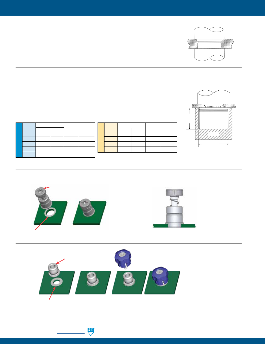
PF-36
PennEngineering •
www.pemnet.com
CAPTIVE PANEL SCREW INSTALLATION
ME
TR
IC
U
NIF
IE
D
Anvil Dimensions (in.)
Thread
A C
Anvil Part
Punch Part
Code
±.002 ±.002 Number Number
440 .225 .298 8006124 975200048
632
.225
.329
8006735 975200048
832
.225
.361
8006736 975200048
032
.225
.392
8006174 975200048
Anvil Dimensions (mm)
Thread
A C
Anvil Part
Punch Part
Code
±0.05 ±0.05 Number Number
M3 5.72 7.57 8006124 975200048
M4
5.72
9.17
8006736 975200048
M5
5.72
9.6
8006174 975200048
PUNCH
ANVIL
A
C
N10™ FASTENERS
1.
Prepare properly sized mounting hole in sheet. Do not perform any secondary
operations such as deburring.
2.
Place fastener into recessed anvil, and place workpiece (preferably the punch side)
over shank of fastener.
3.
With installation punch and anvil surfaces parallel, apply squeezing force until the
shoulder of the nut comes in contact with the sheet material.
PEMSERTER® Installation Tooling
(1)
PUNCH
ANVIL
PR10™ FASTENERS
1.
Prepare properly sized mounting hole in sheet. Do not perform any
secondary operations such as deburring.
2.
Place fastener into the mounting hole.
3.
With installation punch and anvil surfaces parallel, apply squeezing force
until the retainer is flush in the sheet.
Solder paste applied
to pad on PCB.
Solder fastener in place
using standard surface
mount techniques.
Screw snapped in place.
Polyimide patch applied
here for vacuum pick up.
Installs in retracted/unfastened position
SMTPF™ RETAINER
SMTPFLSM™ CAPTIVE PANEL SCREWS
Solder paste applied
to pad on PCB.
Solder fastener in place
using standard surface
mount techniques.
Polyimide patch applied
here for vacuum pick up.
(1) Punches and anvils should be hardened.
pem-html.html
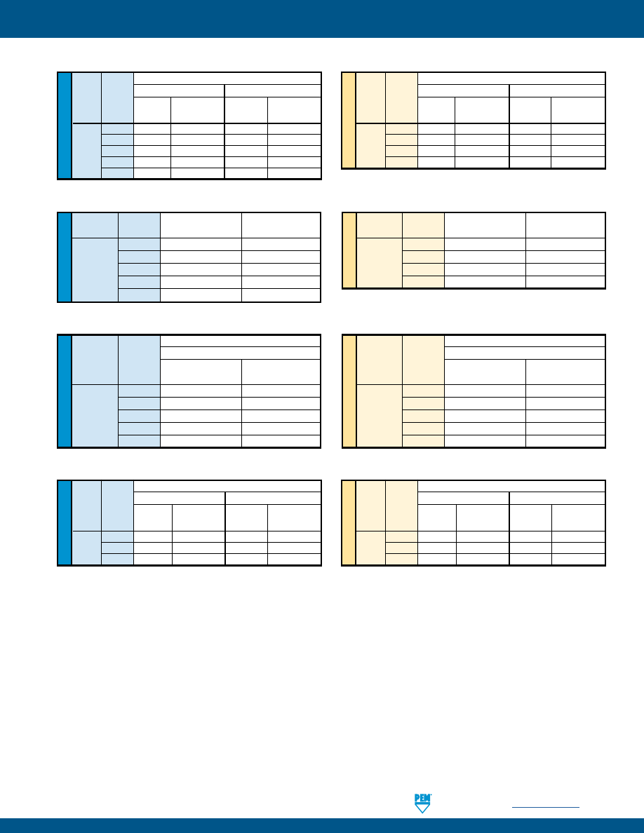
PennEngineering •
www.pemnet.com
PF-37
CAPTIVE PANEL SCREW PERFORMANCE DATA
(1)
(1) Published installation forces are for general reference. Actual set-up and confirmation of complete installation should be made by observing
proper seating of fastener as described in the installation steps. Other performance values reported are averages when all proper
installation parameters and procedures are followed. Variations in mounting hole size, sheet material, and installation procedure may affect
performance. Performance testing this product in your application is recommended. We will be happy to provide technical assistance and/
or samples for this purpose.
U
NIF
IE
D
Test Sheet Material
Type Thread
Aluminum
Cold-Rolled Steel
Code Installation Retainer Pushout
Installation
Retainer Pushout
(lbs.) (lbs.) (lbs.) (lbs.)
440 1500
80
2500
145
PF11 632 2000
95
3500
150
PF12 832 3000
100
4500
160
032 3000
100
4500
160
0420 3500
105
5000
195
ME
TR
IC
Test Sheet Material
Type Thread
Aluminum
Cold-Rolled Steel
Code Installation Retainer Pushout
Installation
Retainer Pushout
(kN) (N) (kN) (N)
M3
6.7
355
11.1
645
PF11
M4
13.3
445
20
710
PF12
M5
13.3
445
20
710
M6
15.6
465
22.2
865
PF11™/PF12™/PF11M™/PF12M™/PEM C.A.P.S.® FASTENERS
U
NIF
IE
D
Type Thread
Installation
Retainer Pullout
Code
(lbs.) (lbs.)
440
250 81
632
300
175
PF11MF
832
350
180
032
350
180
0420
400
200
ME
TR
IC
Type Thread
Installation
Retainer Pullout
Code
(kN) (N)
M3
1.1 360
PF11MF
M4
1.5 800
M5
1.5
800
M6
2
890
PF11MF™ FASTENERS
U
NIF
IE
D
Test Sheet Material
Type Thread
.060” Cold-rolled Steel
Code
Swaging Force
Retainer Pullout
(lbs.) (lbs.)
440
350
112
632
400
138
PF11MW
832
700
202
032
700
202
0420
900
212
ME
TR
IC
Test Sheet Material
Type Thread
1.52mm Cold-rolled Steel
Code
Swaging Force
Retainer Pullout
(N) (N)
M3
1557
499
M3.5
1779
612
PF11MW
M4
3114
897
M5
3114
897
M6
4003
945
PF11MW™ FASTENERS
U
NIF
IE
D
Test Sheet Material
Type Thread
Aluminum
Cold-Rolled Steel
Code Installation Retainer Pushout
Installation
Retainer Pushout
(lbs.) (lbs.) (lbs.) (lbs.)
440
1700
108
2200
118
PFHV 632 1850
117
2400
128
832 2100 134
2700
147
ME
TR
IC
Test Sheet Material
Type Thread
Aluminum
Cold-Rolled Steel
Code Installation Retainer Pushout
Installation
Retainer Pushout
(kN) (N) (kN) (N)
M3
8.1
516
10.5
564
PFHV M3.5 8.8
561
11.4
614
M4 9.4 599
12.1
656
PFHV™ FASTENERS
pem-html.html
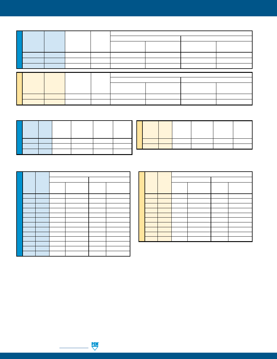
PF-38
PennEngineering •
www.pemnet.com
CAPTIVE PANEL SCREW PERFORMANCE DATA
(1)
PF
7
M™ FASTENERS
U
NIF
IE
D
Rec.
Min.
Test Sheet Material
Tightening
Screw
Aluminum
Cold-rolled
Steel
Type
Thread
Torque
Tensile
Code (in. lbs.) (2)
(lbs.)
Installation
Retainer Pushout
Installation
Retainer Pushout
(lbs.)
(lbs.) (lbs.) (lbs.)
PF
7M 440
4.5 580
1500 80 2500 145
PF
7M 632
8.6 855
2000 95 3500 150
PF
7M 832 15.6 1300
3000 100 4500 160
ME
TR
IC
Rec.
Min.
Test Sheet Material
Tightening
Screw
5052-H34 Aluminum
Cold-rolled Steel
Type
Thread
Torque
Tensile
Code
(N • m) (2)
(N)
Installation
Retainer Pushout
Installation
Retainer Pushout
(kN) (N) (kN) (N)
PF
7M M3 0.66 2900
6.7 355 11.1 645
PF
7M M4 1.57 5010
13.3 445 20 710
PF
7
MF™ FASTENERS
U
NIF
IE
D
Rec.
Tightening
Min. Screw
Retainer
Type Thread Torque
Tensile
Installation
Pullout
Code
(in. lbs.) (2)
(lbs.)
(lbs.)
(lbs.)
PF7MF 440 4.5
580
250
81
PF
7MF 632 8.6
855
300
175
PF
7MF 832 15.6
1300
350
180
ME
TR
IC
Rec.
Tightening
Min. Screw
Retainer
Type Thread Torque
Tensile
Installation
Pullout
Code
(N•m) (2)
(N)
(kN)
(N)
PF7MF M3 0.66
2900
1.1
360
PF
7MF M4 1.57
5010
1.5
800
(1) Published installation forces are for general reference. Actual set-up and confirmation of complete installation should be made by observing
proper seating of fastener as described in the installation steps. Other performance values reported are averages when all proper
installation parameters and procedures are followed. Variations in mounting hole size, sheet material, and installation procedure may affect
performance. Performance testing this product in your application is recommended. We will be happy to provide technical assistance and/
or samples for this purpose.
(2) Torque values shown will produce a preload of 70% minimum tensile with nut factor “k” equal to .1
U
NIF
IE
D
Test Sheet Material
Type Thread
Aluminum
Cold-Rolled Steel
Code Installation Retainer Pushout Installation
Retainer Pushout
(lbs.) (lbs.) (lbs.) (lbs.)
PF30
440
2200
64
5000
90
PF31
440
2200
105
5000
110
PF32
440
2200
185
5000
300
PF30
632
2400
66
5500
90
PF31
632
2400
105
5500
130
PF32
632
2400
190
5500
300
PF30
832
2800
68
6000
90
PF31
832
2800
110
6000
130
PF32
832
2800
200
6000
300
PF30
032
3500
72
8000
95
PF31
032
3500
150
8000
160
PF32
032
3500
260
8000
425
PF32
0420
4300
320
12000
450
ME
TR
IC
Test Sheet Material
Type Thread
Aluminum
Cold-Rolled Steel
Code Installation Retainer Pushout Installation
Retainer Pushout
(kN) (N) (kN) (N)
PF30
M3
9.8
285
22.2
400
PF31
M3
9.8
465
22.2
489
PF32
M3
9.8
823
22.2
1334
PF30
M4
12.5
302
26.7
400
PF31
M4
12.5
489
26.7
578
PF32
M4
12.5
890
26.7
1334
PF30
M5
15.6
320
35.6
423
PF31
M5
15.6
667
35.6
712
PF32
M5
15.6
1156
35.6
1890
PF32
M6
19.1
1423
53.4
2002
PF30™/PF31™/PF32™ FASTENERS
pem-html.html
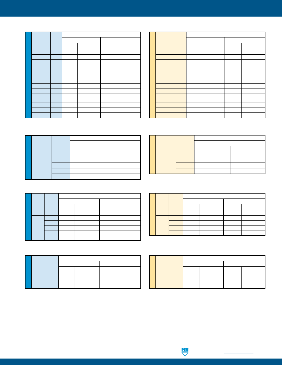
PennEngineering •
www.pemnet.com
PF-39
CAPTIVE PANEL SCREW PERFORMANCE DATA
(1)
(1) Published installation forces are for general reference. Actual set-up and confirmation of complete installation should be made by observing
proper seating of fastener as described in the installation steps. Other performance values reported are averages when all proper installation
parameters and procedures are followed. Variations in mounting hole size, sheet material, and installation procedure may affect performance.
Performance testing this product in your application is recommended. We will be happy to provide technical assistance and/or samples for
this purpose.
PF50™/PF51™/PF52™/PF60™/PF61™/PF62™ FASTENERS
U
NIF
IE
D
Test Sheet Material
Type Thread Aluminum
Cold-Rolled Steel
Code
Installation Retainer Pushout Installation Retainer Pushout
(lbs.) (lbs.) (lbs.) (lbs.)
PF50/PF60
440
2200
64
5000
90
PF51/PF61
440
2200
105
5000
110
PF52/PF62
440
2200
185
5000
300
PF50/PF60
632
2400
66
5500
90
PF51/PF61
632
2400
105
5500
130
PF52/PF62
632
2400
190
5500
300
PF50/PF60
832
2800
68
6000
90
PF51/PF61
832
2800
110
6000
130
PF52/PF62
832
2800
200
6000
300
PF50/PF60
032
3500
72
8000
95
PF51/PF61
032
3500
150
8000
160
PF52/PF62
032
3500
260
8000
425
PF52/PF62 0420
4300
320
12000
450
ME
TR
IC
Test Sheet Material
Type Thread Aluminum
Cold-Rolled Steel
Code
Installation Retainer Pushout Installation Retainer Pushout
(kN) (N) (kN) (N)
PF50/PF60 M3
9.8
285
22.2
400
PF51/PF61 M3
9.8
465
22.2
489
PF52/PF62 M3
9.8
823
22.2
1334
PF50/PF60 M3.5
10.7
294
24.4
400
PF51/PF61 M3.5
10.7
465
24.4
578
PF52/PF62 M3.5
10.7
845
24.4
1334
PF50/PF60 M4
12.5
302
26.7
400
PF51/PF61 M4
12.5
489
26.7
578
PF52/PF62 M4
12.5
890
26.7
1334
PF50/PF60 M5
15.6
320
35.6
423
PF51/PF61 M5
15.6
667
35.6
712
PF52/PF62 M5
15.6
1156
35.6
1890
PF52/PF62 M6
19.1
1423
53.4
2002
U
NIF
IE
D
Test Sheet Material
Type Thread
Aluminum
Cold-Rolled Steel
Code Installation Retainer Pushout
Installation Retainer Pushout
(lbs.) (lbs.) (lbs.) (lbs.)
440 2400
240
3000
300
PFC2 632 2700
275
3500
350
PFS2 832 2900
300
3800
400
PFC2P 032 3000
400
4000
500
0420 3500
400
5000
600
ME
TR
IC
Test Sheet Material
Type Thread
Aluminum
Cold-Rolled Steel
Code Installation Retainer Pushout
Installation Retainer Pushout
(kN) (N) (kN) (N)
M3
10.7
1068
13.3
1334
PFC2
M4 12.9
1334
16.9
1779
PFS2
M5 13.3
1779
17.8
2224
PFC2P
M6 15.6
1779
22.2
2669
PFC2™/PFS2™/PFC2P™ FASTENERS
ME
TR
IC
U
NIF
IE
D
Test Sheet Material
Type Thread
304 Stainless Steel
Code
Installation
Retainer Pushout
(lbs.) (lbs.)
440
9100
350
PFC4
632
10300 400
832
10800
450
032
11800
550
Test Sheet Material
Type Thread
304 Stainless Steel
Code
Installation
Retainer Pushout
(kN) (N)
M3
40.5
1557
PFC4
M4
48
2002
M5
52.5
2447
PFC4™ FASTENERS
U
NIF
IE
D
Test Sheet Material
Type
Aluminum
Cold-Rolled Steel
Installation Retainer Pushout
Installation Retainer Pushout
(lbs.) (lbs.) (lbs.) (lbs.)
PTL2 3000 400 4000 500
PSL2
ME
TR
IC
Test Sheet Material
Type
Aluminum
Cold-Rolled Steel
Installation Retainer Pushout
Installation Retainer Pushout
(kN) (N) (kN) (N)
PTL2 13.3 1779 17.8 2224
PSL2
PTL2™/PSL2™ FASTENERS
pem-html.html
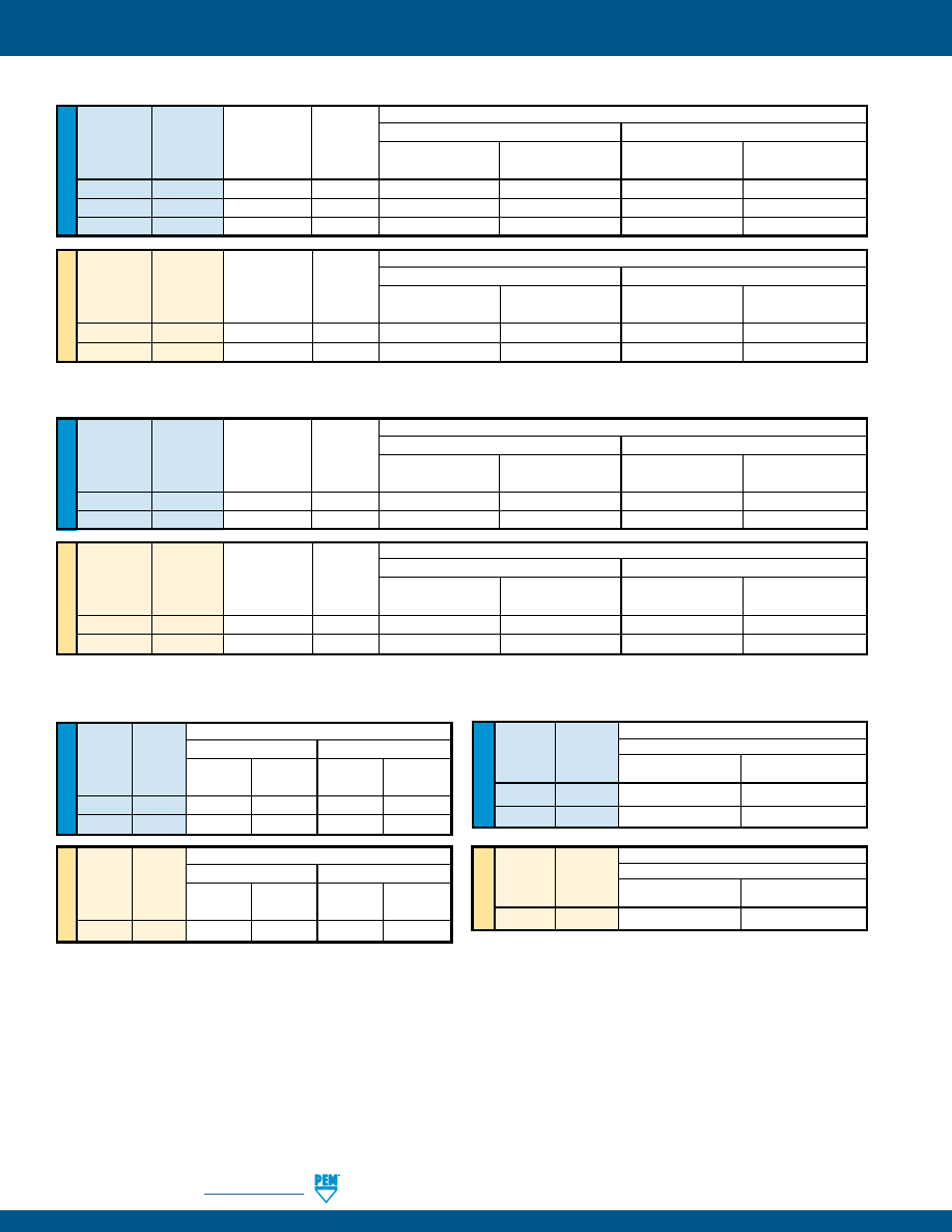
PF-40
PennEngineering •
www.pemnet.com
CAPTIVE PANEL SCREW PERFORMANCE DATA
(1)
SCB™/SCBJ™ FASTENERS
SCBR™ FASTENERS
(1) Published installation forces are for general reference. Actual set-up and confirmation of complete installation should be made by observing
proper seating of fastener as described in the installation steps. Other performance values reported are averages when all proper
installation parameters and procedures are followed. Variations in mounting hole size, sheet material, and installation procedure may affect
performance. Performance testing this product in your application is recommended. We will be happy to provide technical assistance and/
or samples for this purpose.
(2) Torque values shown will produce a preload of 70% minimum tensile (125 ksi / 935 MPa) with nut factor “k” equal to .1
U
NIF
IE
D
Rec.
Min.
Test Sheet Material
Tightening
Screw
5052-H34 Aluminum
Cold-rolled Steel
Type
Thread
Torque
Tensile
Code (in. lbs.) (2)
(lbs.)
Installation Pushout Installation Pushout
(lbs.)
(lbs.) (lbs.) (lbs.)
SCBR 440
5
590
1900 130 2600 145
SCBR
632
9
990
2000
175
3500
200
SCBR
832
17
1460
2250
225
3825
260
ME
TR
IC
Rec.
Min.
Test Sheet Material
Tightening
Screw
5052-H34 Aluminum
Cold-rolled Steel
Type
Thread
Torque
Tensile
Code
(N • m) (2)
(N)
Installation Pushout Installation
Pushout
(kN) (N) (kN) (N)
SCBR M3 0.74 3400
8 580 12 650
SCBR M4
1.7 5700
10 1000 17 1150
U
NIF
IE
D
Rec.
Min.
Test Sheet Material
Tightening
Screw
5052-H34 Aluminum
Cold-rolled Steel
Type
Thread
Torque
Tensile
Code (in. lbs.) (2)
(lbs.)
Installation Pushout Installation Pushout
(lbs.)
(lbs.) (lbs.) (lbs.)
SCB / SCBJ
440
5
590
1900
130
2600
145
SCB / SCBJ
632
9
990
2000
175
3500
200
ME
TR
IC
Rec.
Min.
Test Sheet Material
Tightening
Screw
5052-H34 Aluminum
Cold-rolled Steel
Type
Thread
Torque
Tensile
Code
(N • m) (2)
(N)
Installation Pushout Installation
Pushout
(kN) (N) (kN) (N)
SCB / SCBJ
M3
0.74
3400
8
580
12
650
SCB / SCBJ
M4
1.7
5700
10
1000
17
1150
U
NIF
IE
D
Type
Thread
Code Installation Pushout Installation Pushout
(lbs.)
(lbs.)
(lbs.)
(lbs.)
HSCB 440 1900 60 2600 80
HSCB
632
2000
90
3500
120
U
NIF
IE
D
Test Sheet Material
Type Thread
.060” FR-4 Panel
Code
Installation
Pushout
(lbs.)
(lbs.)
HSR
440
400
65
HSR 632
500 80
ME
TR
IC
Test Sheet Material
Type Thread
1.5mm FR-4 Panel
Code
Installation
Pushout
(kN)
(N)
HSR
M3
2.2
290
Test Sheet Material
Aluminum
Cold-rolled Steel
ME
TR
IC
Type Thread
Code Installation Pushout Installation Pushout
(kN)
(N) (kN) (N)
HSCB M3
8
265
12
355
Test Sheet Material
Aluminum
Cold-rolled Steel
HSCB™ FASTENERS
HSR™ FASTENERS
pem-html.html
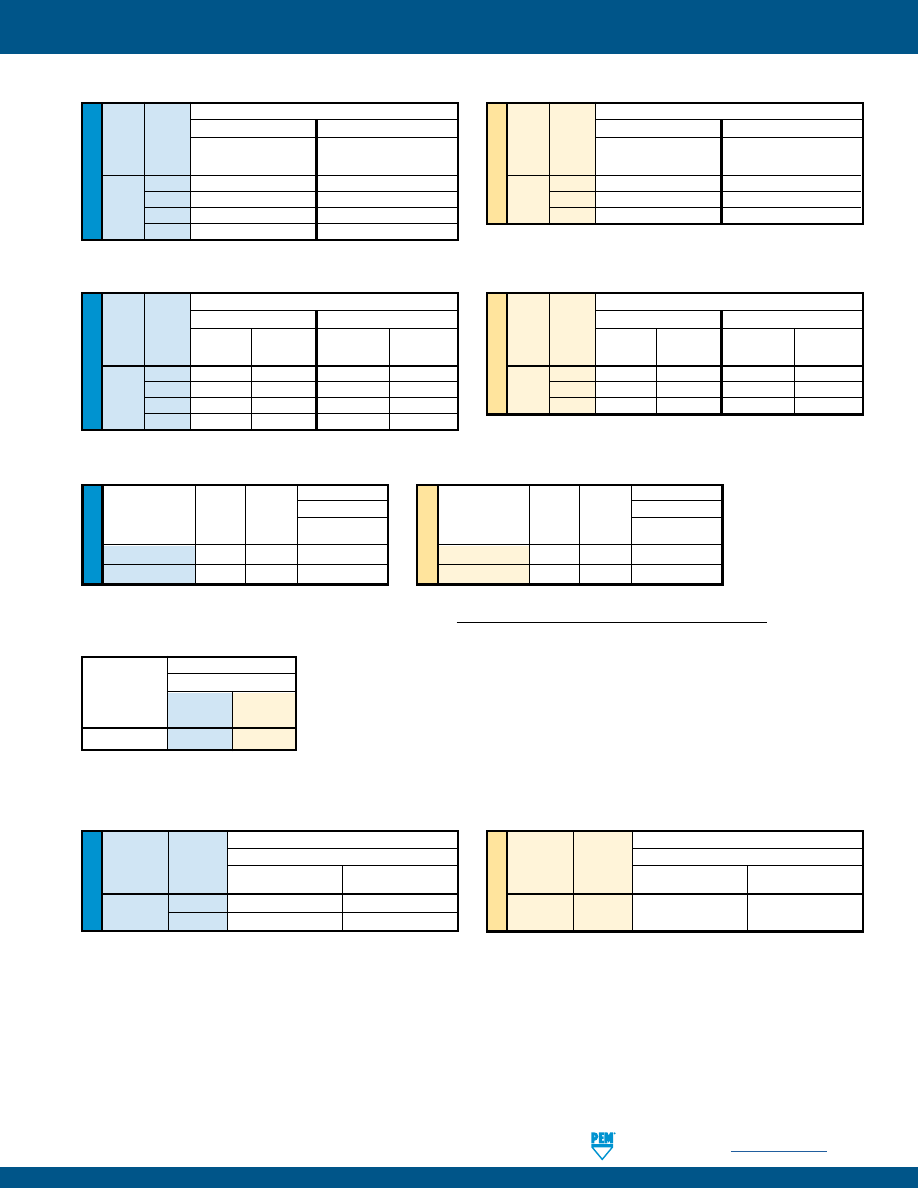
PennEngineering •
www.pemnet.com
PF-41
CAPTIVE PANEL SCREW PERFORMANCE DATA
(1)
REELFAST® SMTPR™ RETAINER
(2)
ME
TR
IC
U
NIF
IE
D
Test Sheet Material
Type
Thread
FR-4 Fiberglass
Code
Installation Pushout
(lbs.) (lbs.)
440
250 55
PFK
632
400 60
Test Sheet Material
Type Thread
FR-4 Fiberglass
Code
Installation Pushout
(kN) (N)
PFK M3
1.1 245
PFK™ FASTENERS
Test Sheet Material
Part .062” Single Layer RF-4
Number
Pushout Pushout
(lbs.) (N)
SMTPR-6-1ET 161.4 718
U
NIF
IE
D
Test Sheet Material
Type Thread
Aluminum
Cold-Rolled Steel
Code Installation Pushout Installation Pushout
(lbs.) (lbs.) (lbs.) (lbs.)
440
2500
95
3600
130
N10
632 2500
105
4000
145
832
3000
110
5000
180
032 3500 120
6300 200
ME
TR
IC
Test Sheet Material
Type Thread
Aluminum
Cold-Rolled Steel
Code Installation Pushout Installation Pushout
(kN) (N) (kN) (N)
M3
11.1
423
16
578
N10
M4
13.3
489
22.2
800
M5
15.6
534
28
890
N10™ FASTENERS
(1) Published installation forces are for general reference. Actual set-up and confirmation of complete installation should be made by observing
proper seating of fastener as described in the installation steps. Other performance values reported are averages when all proper installation
parameters and procedures are followed. Variations in mounting hole size, sheet material, and installation procedure may affect performance.
Performance testing this product in your application is recommended. We will be happy to provide technical assistance and/or samples for
this purpose.
(2) With lead-free paste. Average values of 30 test points. The data presented here is for general comparison purposes only. Actual performance is
dependent upon application variables. We will be happy to provide samples for you to install. If required, we can also test your installed hardware and
provide you with the performance data specific to your application.
(3) Torque values shown will produce a preload of 70% minimum tensile with a nut factor “k” equal to .1.
(4) Failure occurred at the solder joint. Screw retention strength is greater than the retainer.
U
NIF
IE
D
Test Sheet Material
Type Thread
Aluminum
Cold-Rolled Steel
Code
Installation Installation
(lbs.) (lbs.)
440
2100
3000
PR10
632
2100
3000
832
2100
3600
032
2400
4200
ME
TR
IC
Test Sheet Material
Type Thread
Aluminum
Cold-Rolled Steel
Code
Installation Installation
(kN) (kN)
M3
9.3
13.3
PR10
M4
9.3
16
M5
10.7
18.7
PR10™ FASTENERS
ME
TR
IC
U
NIF
IE
D
REELFAST® SMTPFLSM™ FASTENERS
(2)
Min. Rec. Test Sheet Material
Type and
Tensile
Tightening
.060” P.C. Board
Thread Size
Strength
Torque
Pull-off
(lbs.)
(in. lbs.)
(3)
(lbs.)
SMTPFLSM-440 556 4.4
100
SMTPFLSM-632
724
7.0
105
Min. Rec. Test Sheet Material
Type and
Tensile
Tightening
1.5 mm P.C. Board
Thread Size
Strength
Torque
Pull-off
(N) (N•m)
(3)
(N)
SMTPFLSM-M3 2900 0.61
445
SMTPFLSM-M3.5
3269
0.8
465
(4)
(4)
TESTING CONDITIONS FOR SMTPFLSM FASTENERS AND SMTPR RETAINER
Oven
Quad ZCR convection oven
High Temp
473˚F / 245˚C
Spokes
2 Spoke Pattern
Board Finish
62% Sn, 38% Pb
Screen Printer
Ragin Manual Printer
Vias
None
Paste
Amtech NC559LF Sn96.5/3.0Ag/0.5Cu (SAC305)
(SMTPR)
Alpha CVP-390 Sn96.5/3.0Ag/0.5Cu (SAC305)
(SMTPFLSM)
Stencil
.0067” / 0.17 mm thick
(SMTPR)
.005” / 0.13 mm thick
(SMTPFLSM)
pem-html.html
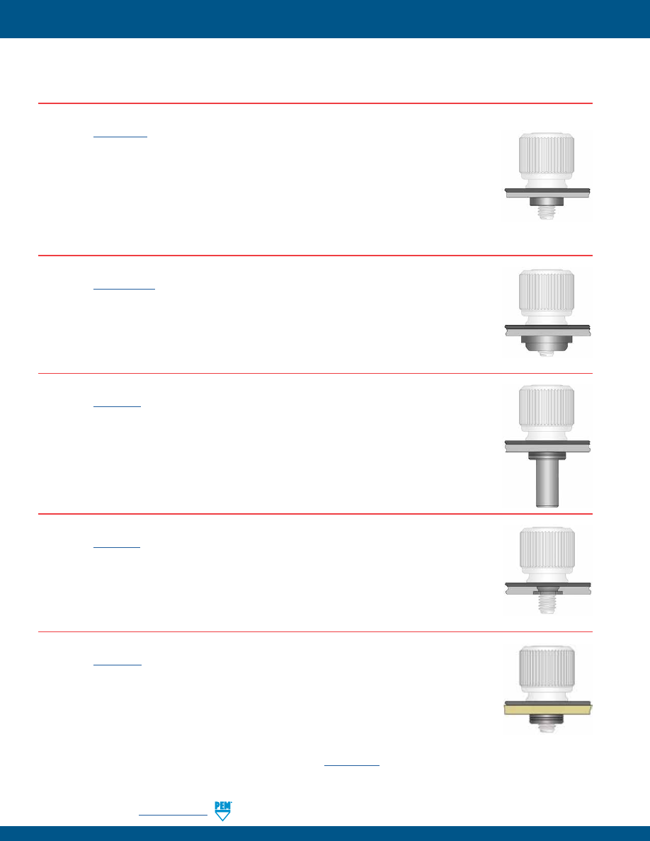
PF-42
PennEngineering •
www.pemnet.com
CAPTIVE PANEL SCREW CAPABILITIES
MOST COMMONLY USED AND RECOMMENDED CAPTIVE MATING HARDWARE
FOR USE WITH CAPTIVE PANEL SCREWS
For the best mating hardware for your application please contact our
Tech Support
line or your local representative.
SELF-CLINCHING NUTS MATED WITH CAPTIVE PANEL SCREW
(See PEM®
Bulletin CL
)
•
S/CLS/SS/CLSS provide load-bearing threads in thin sheets with high pushout and torque-out resistance.
•
SP nuts provide load-bearing threads in stainless steel sheets with a hardness of HRB 90 (Rockwell “B”
scale) / HB 192 (Hardness Brinell) or less.
•
CLA aluminum nuts are recommended for aluminum sheets with a hardness of HRB 50 (Rockwell “B”
scale) / HB 89 (Hardness Brinell) or less.
•
SMPS nuts are for installation into ultra-thin sheets and can be mounted closer to the edge of a sheet than
other self-clinching nuts.
•
SL nuts have a unique TRI-DENT® locking feature which meets demanding locking performance requirements.
AS/AC/A4 FLOATING NUTS MATED WITH CAPTIVE PANEL SCREW
(See PEM®
Bulletin ALA
)
•
AS (carbon steel) and AC (300 series stainless steel) floating nuts install into sheets with hardness up to HRB
70 / HB 125 on the Rockwell “B” scale.
•
A4 (400 series stainless steel) floating nuts install into sheets with hardness up to HRB 88 / HB 183 on the
Rockwell “B” scale.
•
Thread locking versions also available.
B/BS BLIND NUTS MATED WITH CAPTIVE PANEL SCREW
(See PEM®
Bulletin B
)
•
B/BS nuts are used in applications requiring closed thread ends.
•
Provides barrier to protect threads against foreign matter.
•
Protects internal components from intrusion of screws.
F FLUSH NUTS MATED WITH CAPTIVE PANEL SCREW
(See PEM®
Bulletin F
)
•
Designed to be completely flush in sheets as thin as .060”/1.5mm.
•
Ideal for applications where a thin sheet requires load-bearing threads but still must remain smooth, with no
protrusions on either surface.
•
The hexagonal head ensures high axial and torsional strength.
•
F nuts can be ordered to conform to US NASM45938/4 specifications.
PC BOARD NUTS MATED WITH CAPTIVE PANEL SCREW
(See PEM®
Bulletin K
)
•
KF2/KFS2 broaching nuts utilize specially formed axially groves that can be mounted into a hole to provide a
permanent, strong, threaded attachment point in PC boards.
•
SMTSO surface mount nuts also available.
pem-html.html
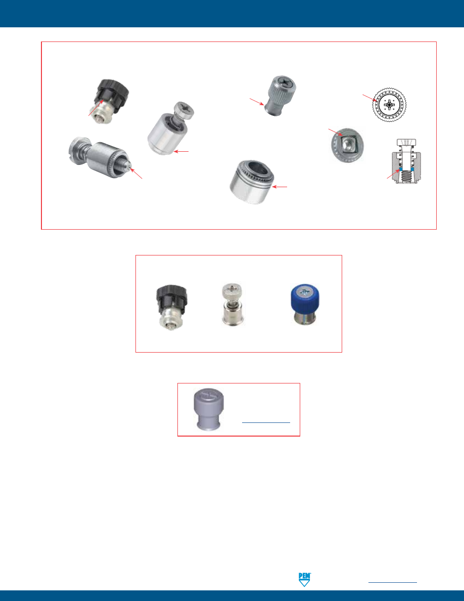
PennEngineering •
www.pemnet.com
PF-43
PEM® FASTENER IDENTIFICATION AND TRADEMARKS
To be sure that you are getting genuine PEM® brand fasteners, look for the unique PEM product markings and identifiers.
Dimple
(Registered Trademark)
PF10, PF30, PF31, PF32, PF50, PF51, PF52, PF60, PF61, PF62,
PF11, PF11M, PF11MF, PF11MW, PF11PM, PF12, PF12M, PF12MF,
PF12MW, PF7M, PF7MF, PFC2, PFC2P, PFC4, PFHV, PFK, PFS2,
PSHP, SCB, SCBJ, SCBR
Single
Groove
(Registered Trademark)
PFC4
Skirted Shoulder
Identifier
(Registered Trademark)
PF11, PF11M, PF11MF,
PF11MW, PF11PM, PF12,
PF12M, PF12MF,
PF12MW, PF7M, PF7MF
Double
Squares
(Registered
Trademark)
F10
Two Groove
(Registered Trademark)
PF7M, PF7MF, N10, HSR
“PEM” Stamp
(Registered
Trademark)
PSHP
PEM C.A.P.S.
Dot Pattern
(Trademark)
PF11PM
Blue Retaining
Ring
(Trademark)
PFC4, PFC2P, PFC2,
PFS2, PFK
These panel fastener styles are protected by U.S. patents:
No. 6,814,530
No. D656,392S
No. D603,693S
Fastener drawings
and models are
available at
www.pemnet.com
pem-html.html

PF-44
All PEM® products meet our stringent quality standards. If you require additional industry or other specific
quality certifications
, special procedures and/or part
numbers are required. Please contact your local sales office or representative for further information.
Regulatory
compliance information
is available in Technical Support section of our website. Specifications subject to change without notice. See our website for the
most current version of this bulletin.
North America:
Danboro, Pennsylvania USA
•
E-mail:
info@pemnet.com
•
Tel: +1-215-766-8853
•
800-237-4736 (USA)
Europe:
Galway, Ireland
•
E-mail:
europe@pemnet.com
•
Tel: +353-91-751714
Asia/Pacific:
Singapore
•
E-mail:
singapore@pemnet.com
•
Tel: +65-6-745-0660
Shanghai, China
•
E-mail:
china@pemnet.com
•
Tel: +86-21-5868-3688
Visit our PEMNET™ Resource Center at
www.pemnet.com
•
Technical support e-mail:
techsupport@pemnet.com
pem-html.html
RIGHT ANGLE
CLINCH FASTENERS
RA
™
217
BULLETIN
pem-html.html
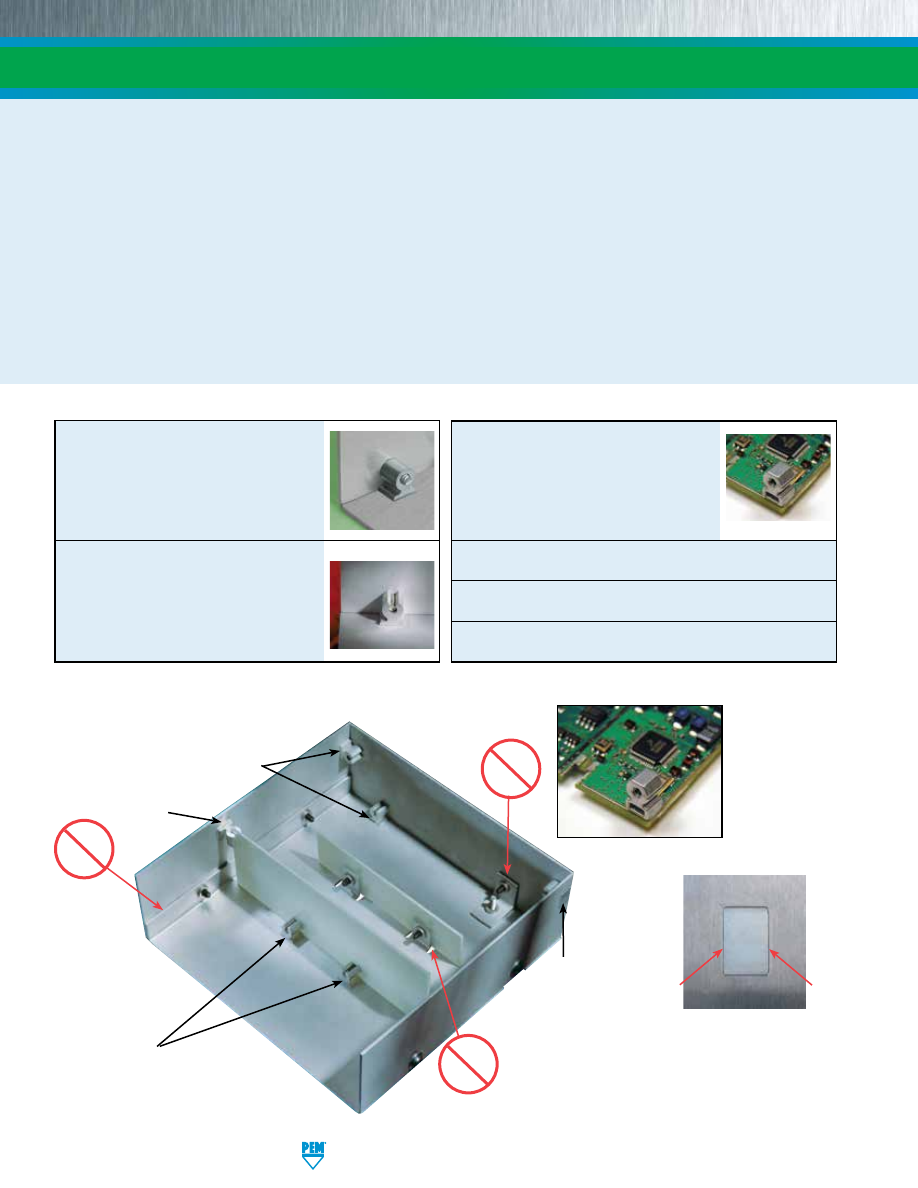
RA-2
PennEngineering • www.pemnet.com
PEM® R’ANGLE® fasteners provide strong right angle attachment points in sheet metal or P.C. boards.
RAA™
and
RAS™
fasteners for metal are simply pressed into a rectangular mounting hole of the proper size.
SMTRA™
fasteners are installed
onto P.C. boards using standard surface mount techniques. The holding power of the fastener is unaffected by the repeated
tightening and loosening of the screw.
PEM® R’ANGLE® fasteners are cost-effective replacements for:
•
Bent edge tabs
•
Bent center tabs
•
Bent flanges
•
Angle brackets
•
Tack welds
•
Loose hardware
PEM® R’ANGLE® fasteners provide many advantages over bent tabs and flanges, including:
•
More predictable designs
•
Material savings
•
Tighter design control
•
Improved shielding characteristics
•
Reduction of loose hardware
•
Fewer assembly steps
•
Unmarred panel surfaces
RIGHT ANGLE CLINCH FASTENERS
RAS™
fasteners for sheet metal is a
threaded right angle fastener that
accepts standard unified or metric
screws
-
PAGE 3
RAA™
right angle fasteners for sheet
metal can accept thread forming or
self-tapping screws
-
PAGE 4
SMTRA™
right angle threaded
fasteners are installed on to PC
boards using standard surface mount
techniques. They accept standard
unified or metric screws
-
PAGE 5
Material and finish specifications -
PAGE 6
Installation -
PAGES 6 - 7
Performance data -
PAGES 7 - 8
Depending on placement
of the fastener within the
mounting hole, a slight
gap may be noticeable
along the non-clinching
edges of the fastener after
installation.
Angle
brackets
Tab
cutouts
Bent
flanges
✓
R’ANGLE
panel
support
✓
R’ANGLE center
mounting
✓
Reverse side
remains flush
with R’ANGLE
fastener
✓
R’ANGLE
edge
mounting
pem-html.html
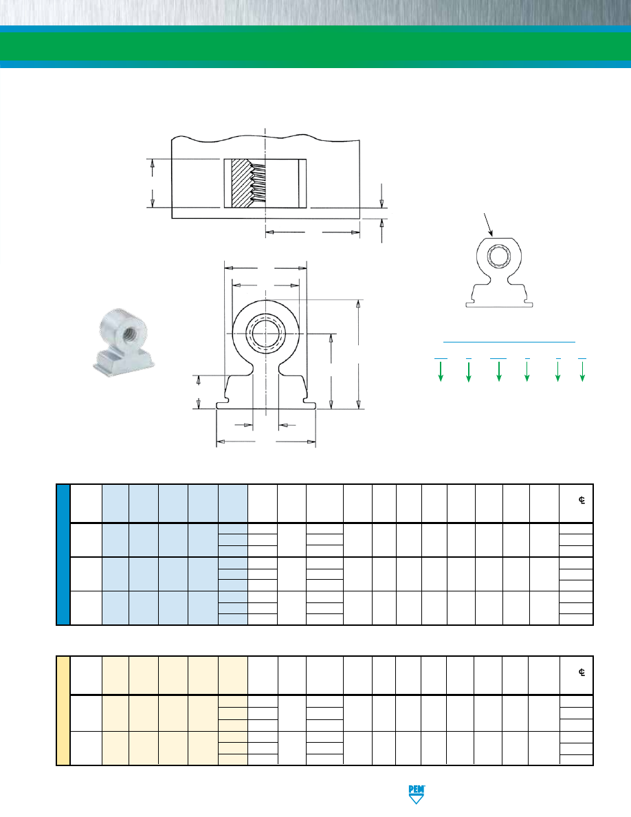
PennEngineering • www.pemnet.com
RA-3
RIGHT ANGLE CLINCH FASTENERS
ME
TR
IC
U
NIF
IE
D
Hole Size
Min. Part Min. Dist.
Thread
Length
Min.
In Sheet
Height
Face to
Hole
CL
Size x
Fastener Thread
Height
Length
L
Sheet
+0.05
A
C
D
E
F
G
J
Edge
To Edge
Pitch Type Material Code Code Code ±0.08 Thickness –0.03
±0.08 Nom. Nom. ±0.15 ±0.15 Nom. Nom.
K
M
3 2.89 8 x 3 7.6
M3 x 0.5
RA
S
M3
7
4
3.89
1
8 x 4
7.89
6.35
3.18
9.47
7
9.78
2.87
1.02
9.1
6
5.89
8
x 6
10.7
4
3.89
10
x 4
10
M4 x 0.7
RA
S
M4
9
7
6.89
1
10 x 7
9.89
8.89
3.18
11.48
9
13.21
4.06
1.02
14.7
9
8.89
10
x 9
16.3
Hole Size
Min. Part Min. Dist.
Length
Min.
In Sheet
Height
Face to
Hole
CL
Thread Fastener
Thread
Height
Length L Sheet +.002 A C D E F G J Edge To
Edge
Size Type Material Code Code Code ±.003 Thickness -.001
±.003 Nom. Nom. ±.006 ±.006 Nom. Nom.
K
M
.112-40
4
.121
.312 x .125
.30
(#4-40)
RA
S
440
9
6
.183
.040
.312 x .187
.308
.250
.125
.370
.281
.406
.096
.040
.35
8
.246
.312 x .250
.43
.138-32
4
.121
.375 x .125
.35
(#6-32)
RA
S
632
10
8
.246
.040
.375 x .250
.371
.300
.125
.433
.312
.462
.141
.040
.50
10
.308
.375 x .312
.55
.164-32
6
.183
.406 x .187
.40
(#8-32)
RA
S
832
12
9
.277
.040
.406 x .281
.402
.350
.125
.464
.375
.550
.157
.040
.58
12
.371
.406 x .375
.65
PEM® RAS™ THREADED RIGHT ANGLE FASTENER
For use with standard metric or unified screws
Metric part can be
identified by flat top
A
F
G
D
E
L
M
K
C
J
All dimensions are in inches.
All dimensions are in millimeters.
Finish
Code
RA
S
440 – 9 – 6
ZI
Type
PART NUMBER DESIGNATION
Length
Code
Thread
Code
Height
Code
Material
(steel)
Clinching profile may vary.
pem-html.html
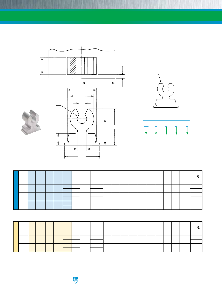
RA-4
PennEngineering • www.pemnet.com
RIGHT ANGLE CLINCH FASTENERS
ME
TR
IC
U
NIF
IE
D
Thread
Hole
Size
Min.
Part
Min.
Dist.
Form
Screw
Length
Min.
In Sheet
Height
Face to
Hole
CL
Screw
Fastener
Size Height Length
L
Sheet
+0.05
A
ØB
C
D
E
F
G
H
J
Edge
To Edge
Size Type Material Code Code Code ±0.08
Thickness –0.03 ±0.08 ±0.1 Nom. Nom. ±0.15 ±0.15 Nom. ±0.18 Nom. K
M
M3 x 0.5 RA
A
M3
7
4 3.89
1
8 x 4
7.89 2.77 6.35 3.18 9.42 7 9.27 1.5 2.87 1.02
9.1
6
5.89 8 x
6 10.7
M4 x 0.7 RA
A
M4
9
7 6.89
1
10 x 7
9.89 3.68 8.89 3.18 11.43 9 12.19 1.97 4.06 1.02
14.7
9
8.89 10 x
9 16.3
Thread
Hole
Size
Min.
Part
Min.
Dist.
Form
Screw
Length
Min.
In
Sheet
Height
Face
to
Hole
CL
Screw
Fastener
Size Height Length
L
Sheet
+.002
A
ØB
C
D
E
F
G
H
J
Edge
To Edge
Size Type Material Code Code Code ±.003 Thickness -.001
±.003 ±.004 Nom. Nom. ±.006 ±.006 Nom. ±.007 Nom.
K
M
#4-40 RA
A
4
9
6 .183
.040
.312 x .187
.308 .100 .250 .125 .368 .281 .389 .054 .096 .040
.35
8
.246
.312 x
.250
.36
#6-32 RA
A
6
10
8 .246
.040
.375 x .250
.371 .123 .300 .125 .431 .312 .442 .066 .141 .040
.50
10
.308 .375 x
.312
.55
#8-32 RA
A
8
12
9 .277
.040
.406 x .281
.402 .145 .350 .125 .462 .375 .525 .078 .157 .040
.58
12
.371
.406
x .375
.65
RAA™ RIGHT ANGLE FASTENER
For use with thread forming screws
Metric part can be
identified by flat top
G
E
ØB
A
D
F
L
M
K
H
C
J
All dimensions are in inches.
All dimensions are in millimeters.
RA – A
4 – 9 – 6
Type
PART NUMBER DESIGNATION
Length
Code
Screw
Size
Code
Height
Code
Material
(aluminum)
Clinching profile may vary.
pem-html.html
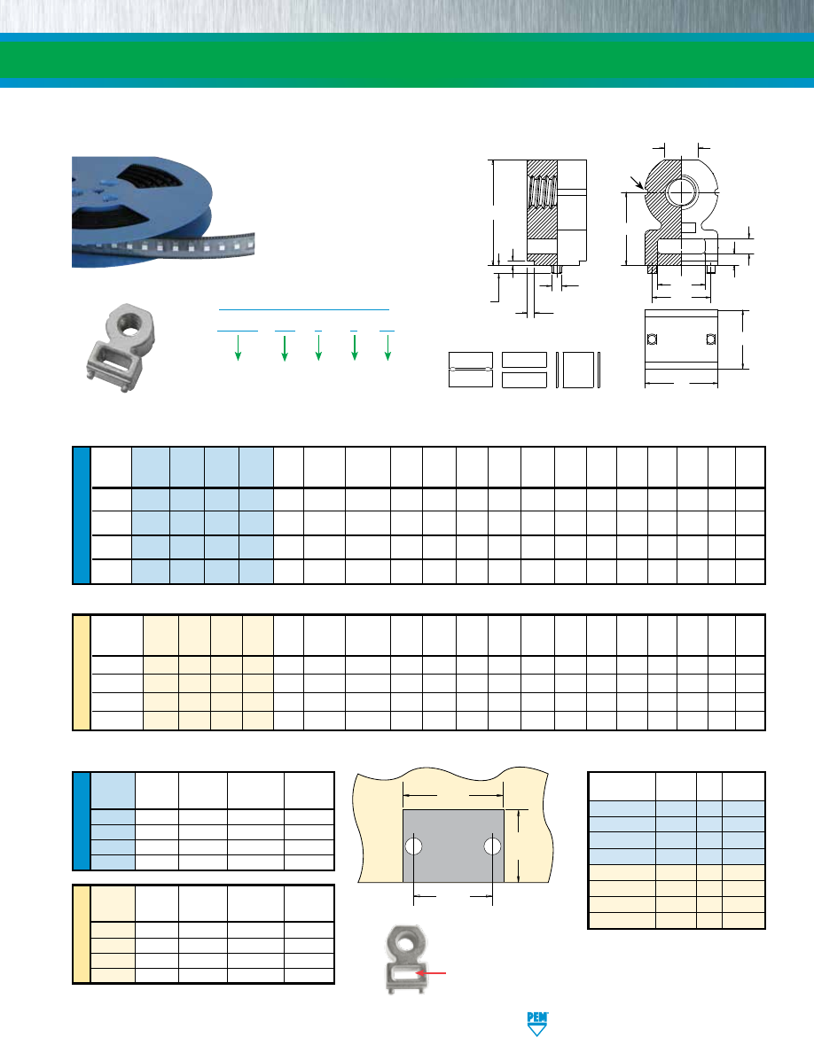
PennEngineering • www.pemnet.com
RA-5
RIGHT ANGLE CLINCH FASTENERS
ME
TR
IC
U
NIF
IE
D
U
NIF
IE
D
ME
TR
IC
Length
Min.
Hole
Size
Height
Thread
Thread Height Length
L
Sheet
In Sheet
A
B
C
D
F
G J K N P S
P
T
Size
Type
Code
Code
Code
±.005 Thickness +.003 –.000 ±.006 ±.006
±.006 ±.006 ±.006
±.006 Nom.
Nom.
Max.
Max.
±.003 Nom.
.086-56
SMTRA 256 8
6 .188 .040
.053 .218 .040 .060 .140 .250 .345 .020 .030 .048 .040 .157 .105
(#2-56)
.112-40
SMTRA 440 9
6 .188 .040
.053 .250 .050 .065 .160 .281 .390 .020 .030 .048 .040 .188 .125
(#4-40)
.138-32
SMTRA 632 10
8 .250 .040
.053 .312 .050 .065 .205 .312 .450 .020 .030 .048 .040 .250 .145
(#6-32)
.164-32
SMTRA 832 12
9 .281 .040
.053 .375 .050 .075 .250 .375 .535 .020 .030 .048 .040 .312 .195
(#8-32)
Thread
Length
Min.
Hole
Size
Height
Size x
Thread Height Length
L
Sheet
In Sheet
A
B
C
D
F
G J K N P S
P
T
Pitch Type Code Code Code ±0.13 Thickness +0.08 ±0.15 ±0.15 ±0.15 ±0.15 ±0.15 ±0.15 Nom. Nom. Max. Max. ±0.08 Nom.
M2 x 0.4 SMTRA M2 6 5 5
1
1.35 5.5 1 1.5 3.5 6 8.4 0.5 0.75 1.22 1 4 2.65
M2.5 x 0.45 SMTRA M25 6
5 5
1
1.35
5.5 1
1.5 3.5 6 8.4 0.5 0.75 1.22 1
4 2.65
M3 x 0.5
SMTRA M3 7 5 5
1
1.35 6.35 1.25 1.65 4
7 9.75 0.5 0.75 1.22 1 4.75 3.2
M4 x 0.7
SMTRA M4 9 7 7
1
1.35 9.53 1.25 1.65 6.35 9 13.1 0.5 0.75 1.22 1 7.9 4.8
Thread Pad Width Pad Length Hole Spacing Hole Size
Code P
A
P
L
S
H
In Sheet
Min.
Min.
±.002
+.003 –.000
256
.262
.171
.157
.053
440
.294
.171
.188
.053
632
.356
.233
.250
.053
832
.419
.264
.312
.053
Thread Pad Width Pad Length Hole Spacing Hole Size
Code P
A
P
L
S
H
In Sheet
Min. Min.
±0.05
+0.08
M2
6.62
4.57
4
1.35
M25
6.62
4.57
4
1.35
M3
7.47
4.57
4.75
1.35
M4
10.65
6.57
7.9
1.35
T
A
C
F
B
G
D
J
K
N
P
S
P
L
Grooves
identify
unified
thread
Part
Parts
Pitch Tape Width
Number
Per Reel (mm)
(mm)
SMTRA256-8-6
375
16
24
SMTRA440-9-6
300
16
24
SMTRA632-10-8
200
20
32
SMTRA832-12-9
200
20
32
SMTRAM2-6-5
375 16
24
SMTRAM25-6-5
375
16
24
SMTRAM3-7-5
300 16
24
SMTRAM4-9-7
200 20
32
Stencil Masking Examples
Solder Pad
P
A
P
L
S
H
Can be flush to
edge. Plated
through hole
not required.
SMTRA™ ReelFast® RIGHT ANGLE FASTENERS
Surface mounted and threaded to accept standard unified or metric screw
All dimensions are in inches.
All dimensions are in millimeters.
SMTRA – 256 – 8 – 6
ET
Type and
Material
(zinc diecast)
PART NUMBER DESIGNATION
Finish
Code
Height
Code
Length
Code
Thread
Code
Patented
If desired, space can
be used for fast cable
tie mounting.
pem-html.html
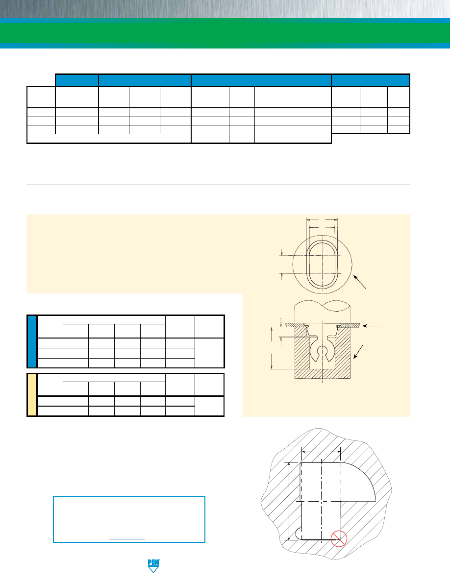
RA-6
PennEngineering • www.pemnet.com
RIGHT ANGLE CLINCH FASTENERS
Threads
Fastener Materials
Standard Finishes
(1)
For Use In Sheet Hardness:
(2)
Internal, ASME
Electro-plated Tin ASTM
HRB 45 /
HRB 60 /
Type
B1.1, 2B ASME
Zinc
Zinc Plated,
B 545, Class A with Clear
HB 84
HB 107
P.C.
B1.13M, 6H
Aluminum
Steel
Diecast
5µm, Colorless
Natural
Preservative Coating, Annealed
or Less
or Less
Board
RAS
•
•
•
•
RAA
•
•
•
SMTRA
•
•
•
•
Part Number Codes for Finishes
ZI
None
ET
(3)
MATERIAL AND FINISH SPECIFICATIONS
ME
TR
IC
U
NIF
IE
D
RAS™ and RAA™ Fasteners
1.
Prepare a properly sized rectangular mounting hole in the sheet. Do
not perform any secondary operations such as deburring.
2.
Place the fastener through the mounting hole (preferably the punch
side) and into the anvil as shown in the drawing to the right.
3.
With the installation punch and anvil surfaces parallel, apply a
squeezing force until the bottom of the fastener becomes flush with
the sheet.
Screw or
Anvil Dimensions (in.)
Thread Size
A
B
C
D
Anvil Part
Punch Part
Code
±.001
±.001
±.005
Min.
Number Number
4 / 440
.257
.313
.100
.425
8002711
6 / 632
.307
.376
.100
.500
8002712
8003076
8 / 832
.357
.407
.100
.575
8003642
Screw or
Anvil Dimensions (mm)
Thread Size
A
B
C
D
Anvil Part
Punch Part
Code ±0.03
±0.03
±0.1
Min.
Number
Number
M3
6.53
8.02
2.54
10.8 8002713
M4
9.07
10.03
2.54
12.7
8002714
8003076
* NOTE:
The punch must be large enough to cover the
entire base of the fastener to ensure proper installation.
Installation tooling is available from PennEngineering.
INSTALLATION
PEMSERTER® Installation Tooling
(1) See PEM Technical Support section of our web site for related plating standards and specifications.
(2) HRB - Hardness Rockwell “B” Scale. HB - Hardness Brinell.
(3) Optimal solderability life noted on packaging.
The mounting hole is defined by two dimensions. The two thick lines
shown must be straight for the entire length defined by “Side 2” and
must be separated by the distance shown as “Side 1” (Side 1 and Side 2
are the two dimensions given for the mounting hole on pages 3 and 4).
The illustration shows three examples (#1, #2, and #3) of how it can be
achieved. Example #4 in the lower right side will not work.
MOUNTING HOLE EXAMPLES
Mounting
Hole
Side 2
Side 1
Hole
Example
#1
Hole
Example
#2
Hole
Example
#3
Hole
Example
#4
PUNCH*
ANVIL
ANVIL
SHEET
B
A
C
D
L + .005”/
0.13mm
Min.
For “L” see
page 3 (RAS)
and page 4
(RAA)
INSTALLATION NOTES
•
For best results we recommend using a PEMSERTER®
press for installation of PEM self-clinching fasteners. Please
check our website for more information.
•
Visit the Animation Library on our website to view the
installation process
for this product
.
pem-html.html
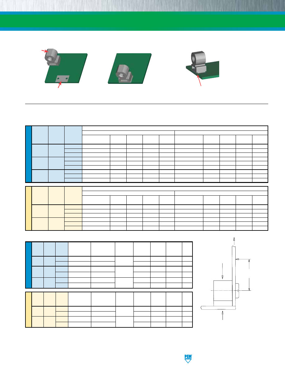
PennEngineering • www.pemnet.com
RA-7
RIGHT ANGLE CLINCH FASTENERS
ME
TR
IC
U
NIF
IE
D
ME
TR
IC
U
NIF
IE
D
Screw
Thread Forming
Max. Rec.
Pushout
Side Load
Pull
Size Height Length
Torque
Tightening Torque
Test Sheet
Installation
(N) (N) Thru
Code Code Code (N•m)
(N•m) Material (kN)
(2)
(3)
(N)
M3
7 4
.17
.56
5052-H34 7.1 556 27 356
6
.23
1.02
Aluminum
7.1
756
44 356
M4
9
7 .56 2.26 5052-H34
13.3 890 76 423
9
.56
2.83
Aluminum 13.3
1045
107 423
Screw
Thread Forming
Max. Rec.
Pushout
Side Load
Pull
Size Height Length
Torque
Tightening Torque
Test Sheet Installation
(lbs.) (lbs.) Thru
Code Code Code
(in. lbs.)
(in. lbs.)
Material
(lbs.)
(2)
(3)
(lbs.)
4
9 6
3
6
5052-H34 1800 140 8 80
8
4
10
Aluminum 1800
180
13
80
6
10
8 5.5
11 5052-H34
2500 175 12 85
10
5.5
17
Aluminum 2500
235
16
85
8
12
9 6.5
18
5052-H34 3100 205 13 105
12
8.0
20
Aluminum 3100
255
21 105
(1) Published installation forces are for general reference. Actual set-up and confirmation of complete installation should be made by observing proper
seating of fastener as described in the installation steps. Other performance values reported are averages when all proper installation parameters
and procedures are followed. Variations in mounting hole size, sheet material, and installation procedure may affect performance. Performance
testing this product in your application is recommended. We will be happy to provide technical assistance and/or samples for this purpose.
(2) Pushout test is conducted without side panel attached to R’ANGLE® fastener.
(3) 1” / 25.4mm from screw centerline.
Test Sheet Material
Thread
Height
Length
5052-H34 Aluminum
Cold-rolled Steel
Code
Code
Code Max. Rec. Tightening Installation Pushout
Side Load
Pull Thru
Max. Rec. Tightening
Installation
Pushout
Side Load
Pull Thru
Torque (in. lbs.)
(lbs.)
(lbs.)
(2)
(lbs.)
(3)
(lbs.)
Torque (in. lbs.)
(lbs.)
(lbs.)
(2)
(lbs.)
(3)
(lbs.)
4
13
1800 100
7
80
16
2400 180
9
80
440
9
6
17
1800
145
8
80
17
2400
260
9
80
8
17
2100 180
13
80
17
3000 315
15
80
4
20
2000 100
7
85
20
2500 190
9
85
632
10
8
21
2500
190
12
85
26
3200
335
16
85
10
21
2800 230 16
85
26
4000 385
20
85
6
20
2400 140
15
100
27
3200 260
11
100
832
12
9
23
3300
195
16
100
29
4200
345
20
100
12
30
3500 260 20
100
35
4700 420
27 100
SIDE VIEW
INSTALLATION
FORCE
1” /
25.4mm
PUSHOUT
(2)
PULL
THRU
SIDE
LOAD
(3)
Test Sheet Material
Thread
Height
Length
5052-H34 Aluminum
Cold-rolled Steel
Code
Code
Code Max. Rec. Tightening Installation Pushout
Side Load
Pull Thru
Max. Rec. Tightening
Installation
Pushout
Side Load
Pull Thru
Torque (N•m)
(kN)
(N)
(2)
(N)
(3)
(N)
Torque (N•m)
(kN)
(N)
(2)
(N)
(3)
(N)
3
1.47
8
423 36
356
2.26
10.7 778
40 356
M3
7
4
1.92
8
534
36
356
2.71
10.7
1001
40
356
6 2.15 9.3
756
58
356 2.71 13.3
1312
67
356
4
2.15
8.9 556 53
423
3.28
11.6 956 44 423
M4
9
7
2.6
13.3
890
76
423
4.07
16
1512
80
423
9
2.83
13.3 1112 93
423
4.52
18.7 1846 116 423
PERFORMANCE DATA
(1)
RAA™ FASTENERS
RAS™ THREADED FASTENERS
Solder paste applied to
pad on PCB.
Solder fastener in place using
standard surface mount techniques.
Undercut to accept solder fillet and
permit flush to edge installation.
Flat top for
vacuum
pick up.
SMTRA™ SURFACE MOUNT FASTENERS
pem-html.html
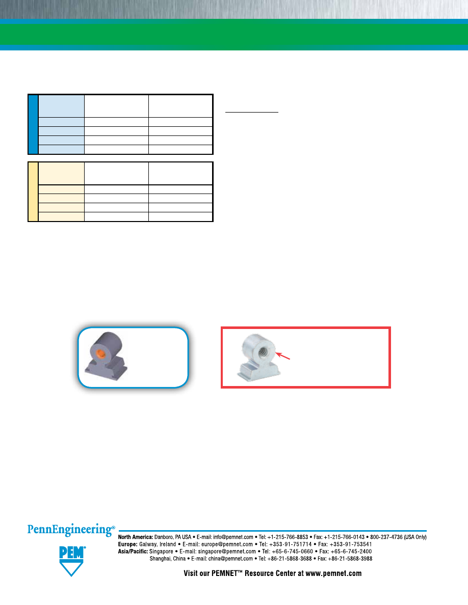
RA-8
PEM® “Circle on Pedestal”
(Registered Trademark)
RIGHT ANGLE CLINCH FASTENERS
SMTRA™ R’ANGLE® FASTENERS WITH ET FINISH
(1)(2)
TESTING CONDITIONS
Oven
Quad ZCR convection oven with 4 zones
Vias
None
High Temp
518˚F / 270˚C
Board Finish
62% Sn, 38% Pb
Paste
Amtech NC559LF Sn96.5/3.0Ag/0.5Cu (SAC305)
Lead-free
Board
.062” thick, Single Layer FR-4
Stencil
.0067” / 0.17 mm thick
Screen Printer
Ragin Manual Printer
(1) With lead-free paste. Average values of 30 test points. The data presented here is for general comparison purposes only. Actual performance is
dependent upon application variables. We will be happy to provide samples for you to install. If required, we can also test your installed hardware
and provide you with the performance data specific to your application.
(2) Further testing details can be found in the literature section on our web site.
PERFORMANCE DATA
U
NIF
IE
D
Part
Pullout
Side Load
Number
(lbs.)
(lbs.)
SMTRA256-8-6
51.7
7.1
SMTRA440-9-6
89.5
10.8
SMTRA632-10-8
110.3
8.4
SMTRA832-12-9
137.2
21.2
ME
TR
IC
Part
Pullout
Side Load
Number
(N)
(N)
SMTRAM2-6-5
418.2
56.8
SMTRAM25-6-5
216.5
36.9
SMTRAM3-7-5
257.6
41.3
SMTRAM4-9-7
369.3
73.3
Fastener drawings
and models are
available at
www.pemnet.com
Technical support e-mail: techsupport@pemnet.com
All PEM® products meet our stringent quality standards. If you require additional industry or other specific quality certifications, special procedures and/or part
numbers are required. Please contact your local sales office or representative for further information.
Regulatory compliance information is available in Technical Support section of our website. Specifications subject to change without notice. See our website for the
most current version of this bulletin.
© 2017 PennEngineering.
pem-html.html
BULLETIN
SF
SPOTFAST® FASTENERS
1115
pem-html.html
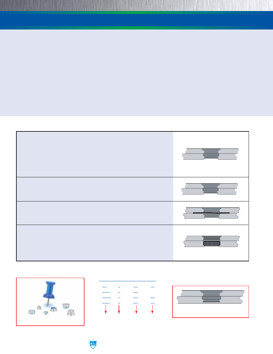
SF-2
PennEngineering • www.pemnet.com
Allows permanent joining in metal to metal and metal to PCB/plastic panels
•
Alternative to riveting and spot welding.
•
No special installation equipment required.
•
Flush or sub-flush on both sides.
•
Minimal space requirements.
•
No countersinking or other hole treatment required.
•
Can be installed blind into bottom (panel 2) sheet.
•
Can be concealed with paints and powder coatings.
•
RoHS compliant.
Unlike rivets that “bulb” during installation, the ultimately flush profile of SpotFast® fasteners allows for unobtrusive
attachment requiring minimal space. A smooth surface is retained for finishing and fasteners can be concealed easily
with paints or powder coatings.
SPOTFAST® FASTENERS
Type SFP
fasteners offer the same benefits as Type SF but are made from
precipitation hardened stainless steel
for installation into stainless steel
sheets.
Type SFW
fasteners offer the same benefits as Type SF but are specifically
designed to allow pivoting of two sheets of metal. A wave washer provides
the consistent torsion to allow repeatable rotation.
Type SFK
flush joining of metal to PCB/plastic panels
Type SF
fasteners create a permanent, flush joining of two sheets. Squeezing
the fastener into place causes a cold-flow of panel material into the fastener’s
two separate clinch profiles. Type SF is
designed for joining metal to metal.
They install smooth with the top sheet, and flush or sub-flush with the bottom
sheet. Fasteners can attach two metal sheets too difficult to weld; fasten
sheets of unequal thicknesses; join dissimilar metals unable to be welded;
and even attach ultra-thin metal sections.
Type
SF -
3 - 1.0 - ZI
SFP - 3 - 1.0
SFW - 3 - 1.0 - LZ
SFK - 3 - 1.0 - ZI
Finish
Thickness
Code
Size
(Panel 1
Mounting
Hole Code)
PART NUMBER DESIGNATION
SpotFast fasteners shown actual size.
Can be installed blind into
bottom (panel 2) sheet.
pem-html.html
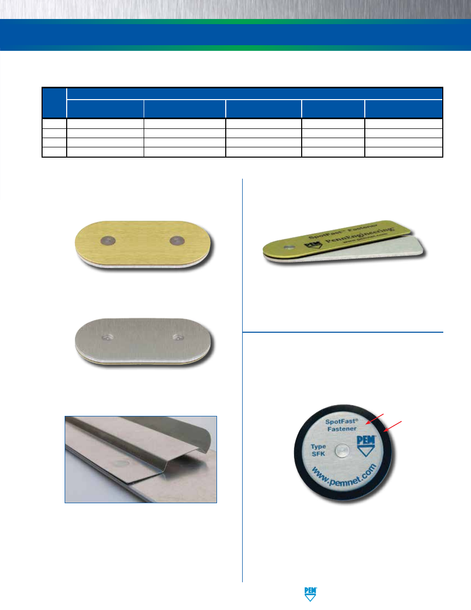
PennEngineering • www.pemnet.com
SF-3
Type SF fastener installed into unequal thickness
sheets. Fastener is smooth with top of panel 1.
Type SF fastener installed sub-flush with panel 2.
Fastener will be flush at minimum sheet thickness.
SPOTFAST® FASTENERS
Type SFW fastener offers flush-
mounted, smooth pivot point.
(1) Not primary use.
Primary Use
Type
Joining two panels of
Joining two panels when
Joining a metal panel to a
Single point hinging
Offers highest corrosion
similar or dissimilar metals
one or more is stainless steel
PCB or plastic panel
applications
resistance in product family
SF
•
•
(1)
SFP
•
(1)
•
•
(1)
•
SFW
•
(1)
•
SFK
•
(1)
•
•
(1)
SPOTFAST
®
FASTENER SELECTOR GUIDE
Sheets as thin as .005” / 0.13 mm may be
attached to thicker sheets using a PEM®
SpotFast® fastener. The thin sheet must be
panel 1 and the “L” dimension must be equal to
or less than the combined panel thicknesses.
Consult our Applications Engineering
department for more information.
Metal
Plastic
Type SFK fastener joining
metal to plastic.
METAL TO METAL
HINGING APPLICATIONS
METAL TO PCB/PLASTIC
pem-html.html
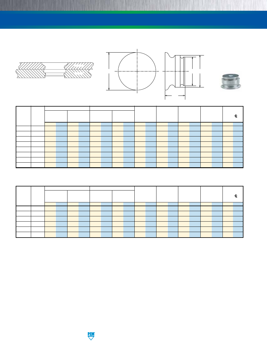
SF-4
PennEngineering • www.pemnet.com
SPOTFAST® FASTENERS
C
2
C
1
L
E
Panel 1
Panel 2
Type
Thickness
Mounting Hole
Thickness
Mounting Hole
Min. Dist.
and
Thickness
±0.08 mm /
+0.08 mm /
Min.
+0.08 mm /
C
1
C
2
E
L
Hole
C/L
Size
Code
±.003”
+.003” –.000”
(1)
+.003” –.000”
Max.
Max.
Max.
Max.
To Edge
mm in. mm in. mm in. mm in. mm in. mm in. mm in. mm in. mm in.
SF-3 0.8 0.8 .031 3 .118 0.8 .031 2.5 .098 2.98 .117 2.48 .097 3.53 .139 1.5 .059 2.54 .1
SF-3 1.0 1 .039 3 .118 1 .039 2.5 .098 2.98 .117 2.48 .097
3.76 .148 1.9 .075
2.54 .1
SF-3 1.2 1.2 .047 3 .118 1.2 .047 2.5 .098 2.98 .117 2.48 .097 3.76 .148 2.31 .091 2.54 .1
SF-3 1.6 1.6 .063 3 .118 1.6 .063 2.5 .098 2.98 .117 2.48 .097 3.76 .148 3.12 .123 2.54 .1
SF-5 0.8 0.8 .031 5 .197 0.8 .031 4 .157 4.98 .196 3.97 .156 5.56 .219 1.5 .059 3.56 .14
SF-5 1.0 1 .039 5 .197 1 .039 4 .157 4.98 .196 3.97 .156 5.56 .219 1.9 .075 3.6 .14
SF-5 1.2 1.2 .047 5 .197 1.2 .047 4 .157 4.98 .196 3.97 .156 5.56 .219 2.31 .091 3.6 .14
SF-5 1.6 1.6 .063 5 .197 1.6 .063 4 .157 4.98 .196 3.97 .156 5.56 .219 3.12 .123 3.6 .14
TYPES SF AND SFP FOR PERMANENT JOINING OF TWO METAL SHEETS
Type SFP for Installation Into Stainless Steel Sheets
Panel 1
Panel 2
Type
Thickness
Mounting Hole
Thickness
Mounting Hole
Min. Dist.
and
Thickness
±0.08 mm /
+0.08 mm /
Min.
+0.08 mm /
C
1
C
2
E
L
Hole
C/L
Size
Code
±.003”
+.003” –.000”
(1)
+.003” –.000”
Max.
Max.
Max.
Max.
To Edge
mm in. mm in. mm in. mm in. mm in. mm in. mm in. mm in. mm in.
SFP-3 1.0 1 .039 3 .118 1 .039 2.5 .098 2.98 .117 2.48 .097
3.76 .148 1.9 .075
2.54 .1
SFP-3 1.2 1.2 .047 3 .118 1.2 .047 2.5 .098 2.98 .117 2.48 .097 3.76 .148 2.31 .091 2.54 .1
SFP-3 1.6 1.6 .063 3 .118 1.6 .063 2.5 .098 2.98 .117 2.48 .097 3.76 .148 3.12 .123 2.54 .1
SFP-5 1.0 1 .039 5 .197 1 .039 4.5 .177 4.98 .196 4.47 .176 5.56
.219 1.9 .075 3.6 .14
SFP-5 1.2 1.2 .047 5 .197 1.2 .047 4.5 .177 4.98 .196 4.47 .176 5.56 .219 2.31 .091 3.6 .14
SFP-5 1.6 1.6 .063 5 .197 1.6 .063 4.5 .177 4.98 .196 4.47 .176 5.56 .219 3.12 .123 3.6 .14
Types SF & SFP installed in sheets.
Panel 1
Panel 2
Patented.
(1) Fastener will provide flush application at minimum sheet thickness.
Type SF
pem-html.html
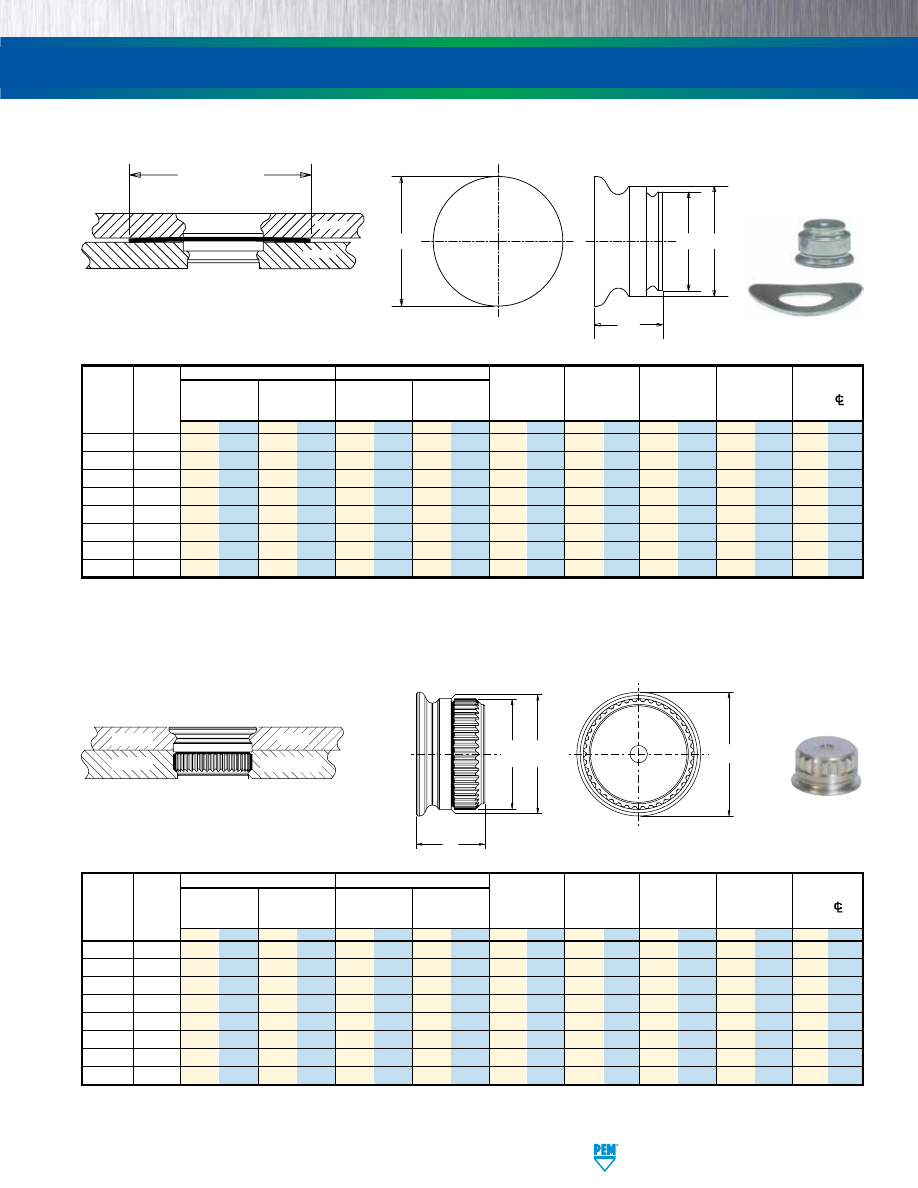
PennEngineering • www.pemnet.com
SF-5
SPOTFAST® FASTENERS
TYPE SFK FOR JOINING METAL TO PCB/PLASTIC PANELS
(1) Fastener will provide flush application at minimum sheet thickness.
(1) Fastener will provide flush application at minimum sheet thickness. (2) Type SFW fasteners are shipped with mating washers.
Panel 1
Panel 2
Type
Thickness
Mounting Hole
Thickness
Mounting Hole
Min. Dist.
and
Thickness
±0.08 mm /
+0.08 mm /
Min.
+0.08 mm /
C
1
C
2
E
L
Hole
C/L
Size
Code
±.003”
+.003” –.000”
(1)
+.003” –.000”
Max.
Max.
Max.
Max.
To Edge
(2) mm in. mm in. mm in. mm in. mm in. mm in. mm in. mm in. mm in.
SFW-3 0.8 0.8 .031 3 .118 0.8 .031 2.5 .098 2.98 .117 2.48 .097 3.53 .139 2.09 .082 2.54 .1
SFW-3 1.0 1 .039 3 .118 1 .039 2.5 .098 2.98 .117 2.48 .097
3.76 .148 2.49
.098
2.54 .1
SFW-3 1.2 1.2 .047 3 .118 1.2 .047 2.5 .098 2.98 .117 2.48 .097 3.76 .148 2.90 .114 2.54 .1
SFW-3 1.6 1.6 .063 3 .118 1.6 .063 2.5 .098 2.98 .117 2.48 .097 3.76 .148 3.71 .146 2.54 .1
SFW-5 0.8 0.8 .031 5 .197 0.8 .031 4 .157 4.98 .196 3.97 .156 5.56 .219 1.98 .078 3.6 .14
SFW-5 1.0 1 .039 5 .197 1 .039 4 .157 4.98 .196 3.97 .156 5.56 .219 2.39
.094 3.6 .14
SFW-5 1.2 1.2 .047 5 .197 1.2 .047 4 .157 4.98 .196 3.97 .156 5.56 .219 2.79 .110 3.6 .14
SFW-5 1.6 1.6 .063 5 .197 1.6 .063 4 .157 4.98 .196 3.97 .156 5.56 .219 3.61 .142 3.6 .14
TYPE SFW WITH WAVE WASHER FOR SINGLE POINT HINGING APPLICATIONS
Type SFW with wave washer installed in sheets.
SFW-3 = 9.7 mm / 0.38” Nom.
SFW-5 = 10.6 mm / 0.42” Nom.
Panel 1
Panel 2
Patented.
Panel 1
Panel 2
Metal
PCB/plastic
Type SFK joining metal to PCB/plastic.
Panel 1
Panel 2
Type
Thickness
Mounting Hole
Thickness
Mounting Hole
C
2
Min. Dist.
and
Thickness
±0.08 mm /
+0.08 mm /
Min.
+0.08 mm /
C
1
±0.08 mm /
E
L
Hole
C/L
Size
Code
±.003”
+.003” –.000”
(1)
+.003” –.000”
Max.
±.003”
Max.
Max.
To Edge
mm in. mm in. mm in. mm in. mm in. mm in. mm in. mm in. mm in.
SFK-3
0.8
0.8 .031 3
.118 1.6 .063 2.5 .098 2.98 .117 2.9 .114 3.53 .139 2.31 .091 3 0.12
SFK-3
1.0
1 .039 3
.118 1.6 .063 2.5 .098 2.98 .117 2.9 .114 3.76 .148 2.51 .099 3 0.12
SFK-3
1.2
1.2 .047 3
.118 1.6 .063 2.5 .098 2.98 .117 2.9 .114 3.76 .148 2.72 .107 3 0.12
SFK-3 1.6 1.6 .063 3 .118 1.6 .063 2.5 .098 2.98 .117 2.9 .114 3.76 .148 3.12 .123 3 0.12
SFK-5 0.8 0.8 .031 5 .197 1.6 .063 4.5 .177 4.98 .196 4.9 .193 5.56 .219 2.31 .091 5.1 0.20
SFK-5 1.0 1 .039 5 .197 1.6 .063 4.5 .177 4.98 .196 4.9 .193 5.56 .219 2.51 .099 5.1 0.20
SFK-5 1.2 1.2 .047 5 .197 1.6 .063 4.5 .177 4.98 .196 4.9 .193 5.56 .219 2.72 .107 5.1 0.20
SFK-5 1.6 1.6 .063 5 .197 1.6 .063 4.5 .177 4.98 .196 4.9 .193 5.56 .219 3.12 .123 5.1 0.20
C
2
C
1
L
E
C
2
C
1
L
E
Washer Diameter
SFW-3 = 0.2 mm / .008” Nom.
SFW-5 = 0.3 mm / .012” Nom.
Washer Compressed Thickness
pem-html.html
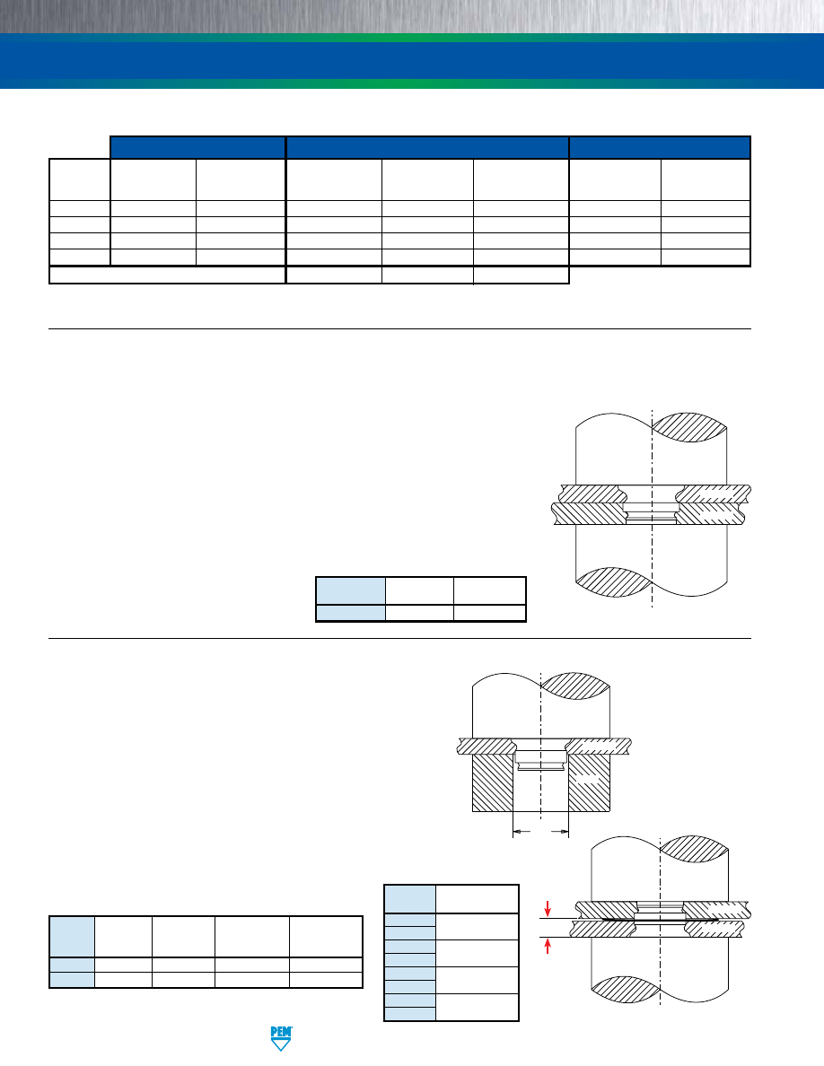
SF-6
PennEngineering • www.pemnet.com
SPOTFAST® FASTENERS
INSTALLATION
Step 1.
Prepare properly sized mounting hole in both panels. Do not perform any secondary
operations such as deburring. If the hole is punched, be sure to install fastener into
punched side of hole.
Step 2.
Place Panel 2 with smaller mounting hole on anvil and align Panel 1 mounting hole
with the mounting hole of Panel 2. Place the smaller diameter end of the fastener
through the mounting holes as shown in the drawing to the right. (See figure SF-1).
Step 3.
With the punch and anvil surfaces parallel, apply squeezing force until the fastener
is flush with the top of Panel 1. (See figure SF-1).
Panel 1
Panel 2
Punch
Anvil
NOTE:
To use Type SF or SFP as a flush-mounted
pivot point, for best results, install SpotFast
fastener into Panel 1 first, then place Panel 2
over fastener and squeeze again.
TYPE SF AND SFP
TYPE SFW
Step 1.
Prepare properly sized mounting hole in both panels. Do not
perform any secondary operations such as deburring. If the hole
is punched, be sure to install fastener into punched side of hole.
Step 2.
Using only Panel 1, with the punch and anvil surfaces parallel,
apply squeezing force until the fastener is flush with the top of
Panel 1. (See figure SFW-1).
Step 3.
To ensure proper function of washer, place washer over installed
fastener (concave side facing up), then place Panel 2 over
fastener. Apply squeezing force. Keep gap between Panel 2 and
anvil. (See “G” in figure SFW-2).
PEMSERTER
®
Installation Tooling
C
Part Number
Part Number
Size
+0.08/+.003
Punch
For Anvil Used
For Anvil Used
(mm) / (in.)
Part No.
In Step 2
In Step 3
SFW-3
3.05 / .120
975200048
970200229300
975200046
SFW-5
5.05 / .199
975200048
970200020300
975200046
C
Punch
Punch
Anvil
Fastener Materials
Standard Finishes
For Use in Sheet Hardness: (2)
Precipitation
Passivated and/or
Zinc Plated, 5µm,
Hardened
Hardening Grade
Tested Per
Zinc Plated, 5µm,
Colorless
HRB 80 /
HRB 88 /
Type
Carbon Steel
Stainless Steel
ASTM A380
Colorless (1)
with Lubricant (1)
HB 150 or Less
HB 183 or Less
SF
•
• •
SFP
• • •
SFW
•
(Washer)
•
(Fastener)
•
SFK
•
• •
Part Number Code For Finishes
None
ZI
LZ
(
1) See PEM Technical Support section of our web site for related plating standards and specifications.
(2) HRB - Hardness Rockwell “B” Scale. HB - Hardness Brinell.
MATERIAL AND FINISH SPECIFICATIONS
Figure SF-1
Figure SFW-1
Figure SFW-2
Panel 1
Anvil
PEMSERTER
®
Installation Tooling
Size
Punch
Anvil
Part No.
Part No.
SF-3 / SF-5
975200048
975200046
G
Panel 2
Panel 1
Size
G
(mm) / (in.)
SFW-3-0.8
1.09-1.25 / .043-.049
SFW-5-0.8
SFW-3-1.0
1.3-1.44 / .051-.057
SFW-5-1.0
SFW-3-1.2
1.5-1.65 / .059-.065
SFW-5-1.2
SFW-3-1.6
1.91-2.06 / .075-.081
SFW-5-1.6
pem-html.html
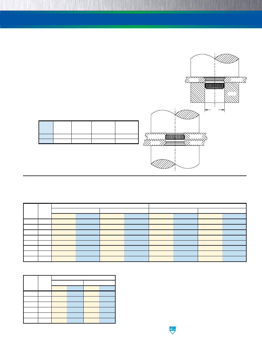
PennEngineering • www.pemnet.com
SF-7
SPOTFAST® FASTENERS
TYPE SF
Stainless Steel
Type and Thickness
Installation
Pushout of Panel 2
(2)
Size
Code
kN lbs. N lbs.
SFP-3
1.0
13.5 3000 620 140
SFP-3 1.2
20 4500 830 186
SFP-3
1.6
22 5000 1500 340
SFP-5
1.0
18 4000 990 222
SFP-5
1.2
27 6000 1158 260
SFP-5
1.6
33 7500 3117 701
TYPE SFP
Installation
Pushout
of
Panel
2
(2)
Type and Thickness
Cold-rolled Steel
Aluminum
Cold-rolled Steel
Aluminum
Size
Code
kN lbs. kN lbs.
N lbs. N lbs.
SF-3 0.8
8 1800 6 1350
360 80 200 45
SF-3 1.0
9 2025 6.5 1475
525 115 250 55
SF-3 1.2
11 2475 7 1575
555 125 310 70
SF-3 1.6
13 2925 7.5 1700
920 205 550 125
SF-5 0.8
11 2475 8 1800
625 140 310 70
SF-5 1.0
12 2700 9.5 2150
800 180 515 115
SF-5 1.2
18 4050 10 2250
1200 270 770 170
SF-5 1.6
20 4500 12.5 2825
1500 335 1145 255
INSTALLATION
PERFORMANCE DATA
(1)
TYPE SFK
Step 1.
Prepare properly sized mounting hole in both panels. Do not
perform any secondary operations such as deburring. If the hole
is punched, be sure to install fastener into punched side of hole.
Step 2.
Using only Panel 1, with the punch and anvil surfaces parallel,
apply squeezing force until the fastener is flush with the top of
Panel 1. (See figure SFK-1).
Step 3.
Place Panel 2 over fastener and apply squeezing force. (See
figure SFK-2).
C
Punch
Punch
Anvil
Panel 1
Metal
Panel 2
PCB/plastic
PEMSERTER
®
Installation Tooling
(1) Published installation forces are for general reference. Actual set-up and
confirmation of complete installation should be made by observing proper seating
of fastener as described in the installation steps. Other performance values
reported are averages when all proper installation parameters and procedures are
followed. Variations in mounting hole size, sheet material, and installation procedure
may affect performance. Performance testing this product in your application is
recommended. We will be happy to provide technical assistance and/or samples
for this purpose.
(2) In most applications, pullout strength of the SpotFast fastener in Panel 1 exceeds pushout
strength of Panel 2.
Figure SFK-1
Figure SFK-2
Panel 1
Metal
Anvil
C
Part Number
Part Number
Size
+0.08/+.003
Punch
For Anvil Used
For Anvil Used
(mm) / (in.)
Part No.
In Step 2
In Step 3
SFW-3
3.05 / .120
975200048
970200229300
975200046
SFW-5
5.05 / .199
975200048
970200020300
975200046
pem-html.html
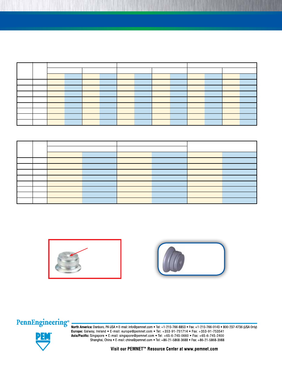
SPOTFAST® FASTENERS
PERFORMANCE DATA
(1)
TYPE SFK
(1) Published installation forces are for general reference. Actual set-up and confirmation of complete installation should be made by observing proper
seating of fastener as described in the installation steps. Other performance values reported are averages when all proper installation parameters
and procedures are followed. Variations in mounting hole size, sheet material, and installation procedure may affect performance. Performance
testing this product in your application is recommended. We will be happy to provide technical assistance and/or samples for this purpose.
(2) In most applications, pullout strength of the SpotFast fastener in Panel 1 exceeds pushout strength of Panel 2.
Installation into Panel 1
Installation into Panel 2
Pushout of Panel 2
(2)
Type and Thickness
Cold-rolled Steel
FR-4 Fiberglass
Size
Code
kN lbs.
kN lbs.
N lbs.
SFK-3
0.8
6.2
1400
1.8
400
200
45
SFK-3
1.0
8
1800
1.8
400
200
45
SFK-3
1.2
8.9
2000
1.8
400
200
45
SFK-3 1.6
10.2
2300
1.8
400
200
45
SFK-5
0.8
11.1
2500
1.8
400
400
90
SFK-5
1.0
13.5
3000
1.8
400
400
90
SFK-5
1.2
15.6
3500
1.8
400
400
90
SFK-5
1.6
17.8
4000
1.8
400
400
90
Installation into Panel 1
Installation into Panel 2
Pushout of Panel 2
(2)
Type and Thickness
Cold-rolled Steel
Aluminum
Cold-rolled Steel
Aluminum
Cold-rolled Steel
Aluminum
Size
Code
kN lbs. kN lbs. kN lbs. kN lbs. N lbs. N lbs.
SFW-3
0.8
4.5
1010
2.5
560
3
675
2
450
350
78
85
19
SFW-3
1.0
5.5
1240
3.5
780
4.5
1010
2
450
375
84
140
31
SFW-3
1.2
6
1350
3.5
780
5
1125
2
450
500
112
250
56
SFW-3
1.6
7
1575
4
900
6
1350
2.5
560
780
175
340
76
SFW-5
0.8
7
1575
3.5
780
8
1800
4
900
350
78
270
61
SFW-5
1.0
7
1575
3.5
780
8.5
1910
5
1125
380
153
425
96
SFW-5
1.2
7
1575
4
900
8.5
1910
5
1125
925
208
510
115
SFW-5
1.6
9
2025
5
1125
10
2250
5
1125
1450
326
600
135
TYPE SFW
Dimple
(Registered
trademark)
SF-8
Technical support e-mail: techsupport@pemnet.com
Specifications subject to change without notice.
See our website for the most current version of this bulletin.
Regulatory compliance information is available in Technical
Support section of our website. © 2015 PennEngineering.
Fastener drawings
and models are
available at
www.pemnet.com
pem-html.html

KEYHOLE
®
STANDOFFS AND FASTENERS
BULLETIN
SK
616
pem-html.html
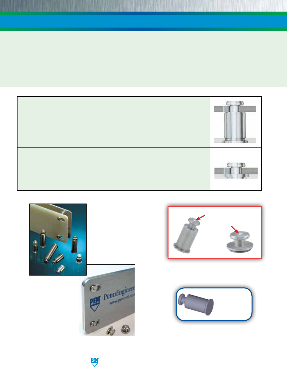
KEYHOLE
®
STANDOFFS AND FASTENERS
PEM
®
Dimple
(Registered trademark)
PEM
®
KEYHOLE
®
Standoffs (Type SKC™) and sheet joining fasteners (Type SKC-F™) are designed so that a PC board or panel
can be quickly slipped into place and then removed from an assembly by simply sliding the board sideways and lifting it off.
PEM KEYHOLE fasteners can save valuable time and dramatically reduce the amount of loose hardware required. Type SKC can
be used for spacing or mounting of replaceable components. Typically, several SKC standoffs are used with one standard PEM
threaded standoff which accepts a screw to secure the board or component against any unwanted movement. Type SKC-F is
designed so that two sheets can be quickly joined flat against each other. Typically, several Type SKC-F fasteners
are used with one standard PEM
®
threaded Type F flush nut which accepts a screw to secure the sheets against any
unwanted movement.
Type SKC - Allows detachable spacing of two sheets
•
Clinch feature mounts fastener permanently into metal sheet.
•
Unique barrel design allows for quick attachment and detachment.
•
Head is flush with one side of metal sheet.
•
Makes horizontal or vertical component mounting possible.
Type SKC-F - Allows detachable joining of two sheets
•
Clinch feature mounts fastener permanently into metal sheet.
•
Unique barrel design allows for quick “panel-on-panel” attachment and detachment.
•
Head is flush or sub-flush with one side of metal sheet.
•
Can be clinched into blind hole where concealed head is required.
•
Makes horizontal or vertical component mounting possible.
Type SKC
Type SKC-F
SK-2
PennEngineering • www.pemnet.com
Fastener drawings
and models are
available at
www.pemnet.com
pem-html.html
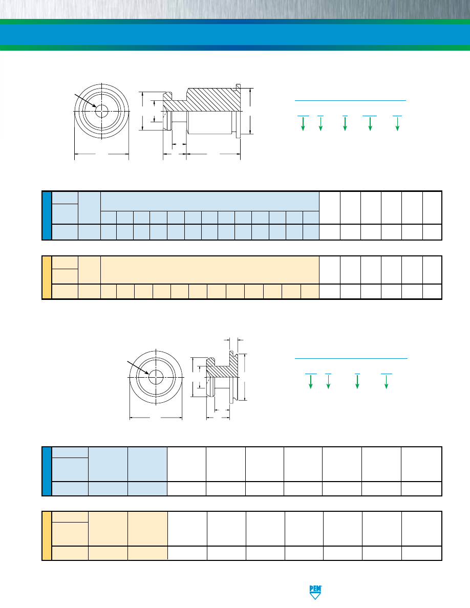
METRIC
UNIFIED
METRIC
UNIFIED
Type
Body
Length “L” ± .005
Size -
(Length Code in 32nds of an inch) A B C S M H
Stainless
Sheet
± .003 ± .003
Max.
± .003 Max.
Nom.
Steel
(1)
Code
.063 .125 .188 .250 .312 .375 .437 .500 .562 .625 .750 .875 1.00
SKC 6060 2 4 6 8 10 12 14 16 18 20 24 28 32 .099 .177 .212 .068 .108 .250
Type
Body
Length “L” ± 0.13
Size -
(Leng th Code in millimeters)
A B C S M H
Stainless
Sheet
±
0.08
±
0.08
Max.
±
0.08
Max.
Nom.
Steel
(1)
Code
SKC 61.5 2 4 6 8 10 12 14 16 18 20 22 25 2.51 4.5 5.39 1.73 2.75
6.35
KEYHOLE
®
STANDOFFS AND FASTENERS
All dimensions are in inches.
All dimensions are in millimeters.
SK C – 6
060 – 12
Type
Body
Size
Code
Length
Code
PART NUMBER DESIGNATION
Material
Code
Sheet
Thickness
Code
Type
Face
Sheet
A B C H M N S
Stainless
Mounting
Thickness
Max.
± .003
Max.
Nom.
Max.
± .003
±.003
Steel
(1)
Designation Code
Code
SKC F 1.5 .039 .177 .212 .237 .108 .099 .068
Type
Face
Sheet
A B C H M N S
Stainless
Mounting
Thickness
Max.
± 0.08
Max.
Nom.
Max.
± 0.08
±0.08
Steel
(1)
Designation Code
Code
SKC F 1.5 1 4.5 5.39 6.02 2.75 2.5 1.73
All dimensions are in inches.
All dimensions are in millimeters.
TYPE SKC-F DIMENSIONAL DATA
TYPE SKC DIMENSIONAL DATA
H
L
C
B A
S
M
PEM “dimple”
registered
trademark.
H
N
C
B
A
S
M
PEM “dimple”
registered
trademark.
PennEngineering • www.pemnet.com
SK-3
SK C – F
1.5
Type
Face
Mounting
Designation
Code
PART NUMBER DESIGNATION
Material
Code
Sheet
Thickness
Code
Clinching profile may vary.
Clinching profile may vary.
(1) 300 Series stainless steel. Passivated and/or tested per ASTM A380.
pem-html.html
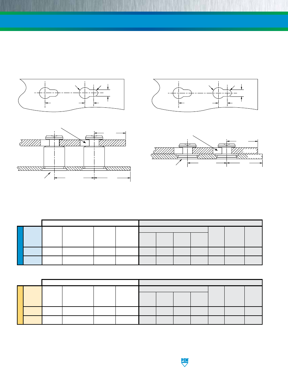
UNIFIED
METRIC
KEYHOLE
®
STANDOFFS AND FASTENERS
Bottom
Sheet
Top Mounting Hole A
Mounting Hardness
Min. Edge
Thickness Edge
Type
Hole B
Max.
Sheet Distance A
1
A
2
A
3
A
4
Material Range Distance
+ .003
(1)
Thickness C
1
Min.
Nom.
± .003
± .003
Min.
C
2
Min.
- .000
SKC
.213
HRB 70 / HB 125
.040
.260
.059
.118
.197
.148
ANY
.057 - .064
.160
SKC-F
.213
HRB 70 / HB 125
.039
(2)
.150
.059
.118
.197
.148
ANY
.057 - .064
.160
PANEL 1
PANEL 2
Bottom
Sheet
Top Mounting Hole A
Mounting
Hardness
Min. Edge
Thickness Edge
Type
Hole B
Max.
Sheet Distance A
1
A
2
A
3
A
4
Material Range Distance
+0.08
(1)
Thickness C
1
Min.
Nom.
± 0.08
± 0.08
Min. C
2
Min.
SKC
5.41
HRB 70 / HB 125
1.02
6.6
1.5
3
5
3.75
ANY
1.45 - 1.62
4.1
SKC-F
5.41
HRB 70 / HB 125
1
(2)
3.8
1.5
3
5
3.75
ANY
1.45 - 1.62
4.1
PANEL 1
PANEL 2
(1) HRB - Hardness Rockwell “B” Scale. HB - Hardness Brinell.
(2) Type SKC-F may also be installed into a .043” / 1.1 mm deep blind milled hole in a .062” / 1.6 mm minimum sheet thickness.
All dimensions are in inches.
All dimensions are in millimeters.
TYPE SKC
TYPE SKC-F
A
1
Rad.
A
3
Dia.
Mounting Hole A
in Panel 2
Edge
C
2
Edge
C
1
Mounting
Hole Location
Tolerance
±.005” / ±0.13 mm
Mounting Hole B
Mounting Hole A
Location
Tolerance
±.005” / ±0.13 mm
PANEL 2
PANEL 1
Edge
C
2
Edge
C
1
PANEL 2
PANEL 1
Mounting Hole B
Mounting Hole A
Mounting
Hole Location
Tolerance
±.005” / ±0.13 mm
A
2
A
4
A
1
Rad.
A
3
Dia.
Mounting Hole A
in Panel 2
Location
Tolerance
±.005” / ±0.13 mm
A
2
A
4
APPLICATION DATA
PennEngineering • www.pemnet.com
SK-4
pem-html.html
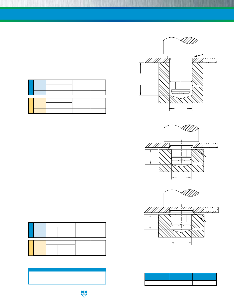
1.
Prepare properly sized mounting hole in Panel 1.
2.
Place the barrel of the fastener through (punched side of)
mounting hole and into anvil as shown in figure 1.
3.
With installation punch and anvil surfaces parallel, apply
only enough squeezing force to embed the head flush with
the panel.
KEYHOLE
®
STANDOFFS AND FASTENERS
TYPE SKC
Through Hole Installation Procedure
1.
Prepare properly sized mounting hole in Panel 1.
2.
Place the fastener into anvil hole as shown in Figure 2.
3.
Place the (punch side of) mounting hole over the shank of the
fastener.
4.
With installation punch and anvil surfaces parallel, apply only
enough squeezing force until flange is flush with panel.
Blind Hole Installation Procedure
1.
Mill a properly sized blind hole to .043” / 1.1 mm minimum depth.
2.
Place the fastener into anvil hole as shown in Figure 3.
3.
Place the panel mounting hole over the shank of the fastener.
4.
With installation punch and anvil surfaces parallel, apply only
enough squeezing force to embed the flange flush with the panel.
TYPE SKC-F
INSTALLATION
Body Size Anvil Dimension (in.)
Sheet
D
Anvil Part
Punch Part
Code
+.003 -.000
Number Number
6060
.216
970200012300 975200048
UNIFIED
Body Size Anvil Dimension (mm)
Sheet
D
Anvil Part
Punch Part
Code
+0.08
Number Number
61.5
5.49
970200012300 975200048
METRIC
Sheet Anvil Dimensions (in.)
Thickness
L D
Anvil Part
Punch Part
Code
Min.
+.003 -.000 Number Number
1.5
.233
.184
8012608 975200048
UNIFIED
Sheet Anvil Dimensions (mm)
Thickness
L D
Anvil Part
Punch Part
Code
Min.
+0.08 Number Number
1.5
5.95
4.67
8012608 975200048
METRIC
SK-5
PennEngineering • www.pemnet.com
PEMSERTER
®
Installation Tooling
PEMSERTER
®
Installation Tooling
For best results we recommend using a PEMSERTER
®
press for installation of PEM Types SKC and SKC-F
fasteners. Please check our website for more information.
PEMSERTER
®
PRESSES
Fastener
Required Size
PEM
Type
End Mill
Part No.
SKC-F .213” CHM-213
End Mill Information
Double-ended, two-flute H.S.S. center-cutting end
mills are available from stock. PennEngineering
does not manufacture center-cutting end mills, but
we do keep a supply in stock for your convenience.
PUNCH
D
(L+M) +.125” /
(L+M) +3.2 mm
Min.
PANEL 1
Figure 1
HEAD
ANVIL
For “L” and “M”
see page 3.
PUNCH
PANEL 1
L
Min.
Figure 2
FLANGE
D
ANVIL
Figure 3
PUNCH
PANEL 1
L
Min.
FLANGE
D
ANVIL
pem-html.html
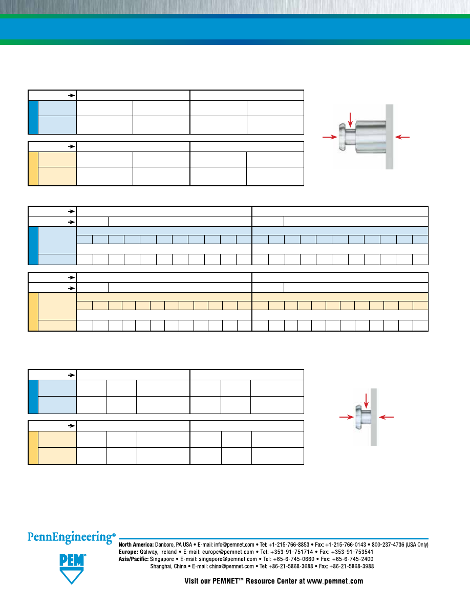
SK-6
KEYHOLE
®
STANDOFFS AND FASTENERS
METRIC
UNIFIED
UNIFIED
METRIC
UNIFIED
(1) Published installation forces are for general reference. Actual set-up and confirmation of complete installation should be made by observing proper
seating of fastener as described in the installation steps. Other performance values reported are averages when all proper installation parameters
and procedures are followed. Variations in mounting hole size, sheet material, and installation procedure may affect performance. Performance
testing this product in your application is recommended. We will be happy to provide technical assistance and/or samples for this purpose.
(2) .040” / 1 mm test sheet material thickness was used for the -2 and -4 SKC standoffs due to the short length of the parts.
Body Size -
Installation
Pushout
Installation
Pushout
Sheet
Code
(lbs.) (lbs.) (lbs.) (lbs.)
6060
1600 250 3200 600
.060” 5052-H34 Aluminum
.060” Cold-Rolled Steel
Body Size -
Installation
Pushout
Installation
Pushout
Sheet
Code
(kN) (N) (kN) (N)
61.5
7.1
1100
14.2
2600
1.52 mm 5052-H34 Aluminum
1.52 mm Cold-Rolled Steel
Installation and Pushout
Body Size -
Sheet Code
6060
Test Sheet Material
5052-H34 Aluminum
Test Sheet Thick. .040”
(2)
.060”
Side-Load
Length Codes
Length Codes
-2 -4 -6 -8 -10 -12 -14 -16 -20 -24 -32 -2 -4 -6 -8 -10 -12 -14 -16 -20 -24 -32
Side-Load Force Max. (lbs.)
Side-Load Force Max. (lbs.)
130 95 82 63 52 44 38 34 27 22 17 185 120 197 153 126
106 92 81 66 55 42
Type
Installation
Pushout
Side-Load Force Max. Installation
Pushout
Side-Load Force Max.
(lbs.) (lbs.)
(lbs.)
(lbs.) (lbs.)
(lbs.)
SKC-F 1100 120
120
2100 160
185
.060” 5052-H34 Aluminum
.060” Cold-Rolled Steel
Type
Installation
Pushout
Side-Load Force Max.
Installation
Pushout
Side-Load Force Max.
(kN) (N)
(N)
(kN) (N)
(N)
SKC-F 4.9 533
533
9.3 711
822
1.52 mm 5052-H34 Aluminum
1.52 mm Cold-Rolled Steel
TYPE SKC
TYPE SKC-F
Installation, Pushout and Side-Load
Cold-Rolled Steel
.040”
(2)
.060”
METRIC
Body Size -
Sheet Code
61.5
Test Sheet Material
5052-H34 Aluminum
Test Sheet Thick.
1 mm
(2)
1.5 mm
Length Codes
Length Codes
-2 -4 -6 -8 -10 -12 -14 -16 -18 -20 -22 -25 -2 -4 -6 -8 -10 -12 -14 -16 -18 -20 -22 -25
Side-Load Force Max. (N)
Side-Load Force Max. (N)
545 370 296 228 184 156 136 116 104 96 88 76 735 490 696 540 440 372 320 280 252 228 208 184
Cold-Rolled Steel
1 mm
(2)
1.5 mm
Test Sheet Material
Test Sheet Material
Test Sheet Material
Test Sheet Material
Side Load
Installation
Force
Pushout
Side Load
Installation
Force
Pushout
PERFORMANCE DATA
(1)
Technical support e-mail: techsupport@pemnet.com
Specifications subject to change without notice.
See our website for the most current version of this bulletin.
Regulatory compliance information is available in Technical
Support section of our website. © 2016 PennEngineering.
pem-html.html

SELF-CLINCHING STANDOFFS
BULLETIN
SO
1116
R
E v
517
pem-html.html
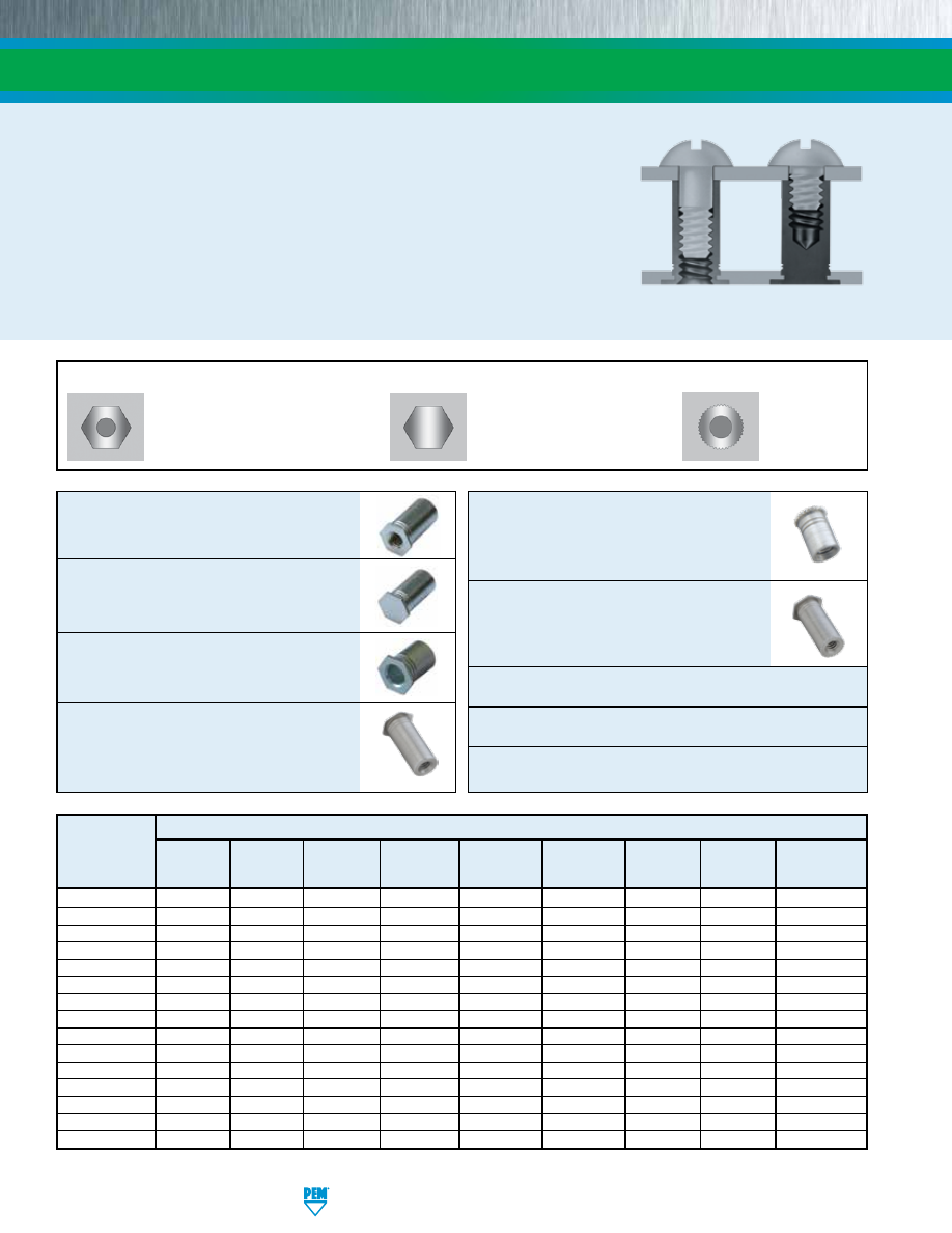
SO-2
PennEngineering • www.pemnet.com
Types SO/SOS/SOA/SO4
Types TSO/TSOS/TSOA/TSO4 (Styles 1 & 2)
Types SOSG/SOAG
PEM® self-clinching standoffs, which use the proven self-clinching design, provide
ideal solutions for applications where mounting, spacing or stacking of panels,
boards or components are required. Pressed into round holes, these fasteners
mount permanently into metal sheets as thin as .025”/0.63mm.
Specially designed Types SO4, BSO4 and TSO4 standoffs are made from hardened
stainless steel and are ideal for clinching into stainless steel sheets. An optional nickel
plating is now available if product is expected to be used in a corrosive environment.
For more information on the proper use of PEM self-clinching standoffs, check our
web site for Tech Sheet PEM® - REF/Standoff Basics.
BLIND
THREADS
THROUGH-HOLE
THREADS
Support This
sheet
SELF-CLINCHING STANDOFFS
Types SO/SOS/SOA/SO4
through hole
threaded self-clinching standoffs
-
PAGE 3
Types BSO/BSOS/BSOA/BSO4
Blind
hole, threaded self-clinching standoffs -
PAGE 4
Types SO/SOS/SOA/SO4
Through hole,
unthreaded self-clinching standoffs
-
PAGE 5
Types TSO/TSOS/TSOA/TSO4
Through
hole threaded standoffs
for clinching
into thinner sheets than type SO
standoffs
-
PAGE 6
Types DSOS/DSO
Through hole,
threaded standoffs with round, knurled
head
allowing closer-to-edge clinch
installation
-
PAGE 7
Types SOSG/SOAG
Through hole,
threaded grounding standoffs with
“gripping teeth” on end of barrel
-
PAGE 7
Material and finish specifications -
PAGE 8
Installation -
PAGES 8 & 9
Performance data -
PAGES 10 & 11
HEAD SIDE OF SHEET AFTER INSTALLATION
A p p l i c a t i o n R e q u i r e s :
PEM
Standoff
Type
BSO
• •
BSOA
• •
BSOS
• • •
BSO4
•
(2)
• •
DSOS
•
SO
•
SOA
•
SOS
• •
SO4
•
(2)
•
SOAG
•
SOSG
• •
TSO
• •
(1)
• •
TSOA
• •
(1)
• •
TSOS
• • •
(1)
• •
TSO4
•
(2)
• •
(1)
• •
(1) Style #3 only.
(2) When used with optional nickel plating.
Types BSO/BSOS/BSOA/BSO4
Types TSO/TSOS/TSOA/TSO4 (Style 3)
Types DSOS/DSO
Installation
Closed-end
Gripping
Closest-to-edge
Thinnest
Most varied
into stainless
Corrosion
Threads at
for flush
teeth on
distance
Available
minimum
standard length
steel
resistance
barrel end
appearance
barrel end
mounting
Unthreaded
sheet
increments
pem-html.html
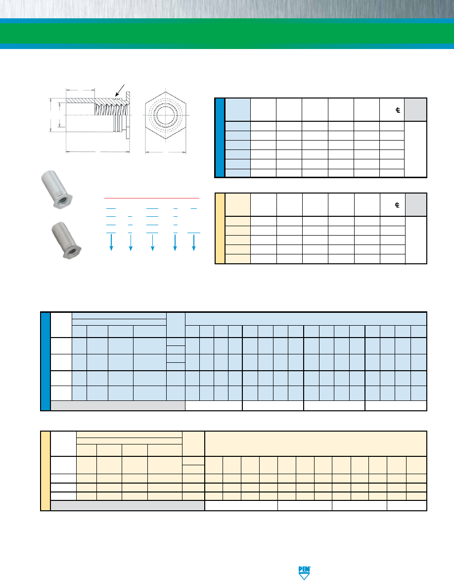
PennEngineering • www.pemnet.com
SO-3
ME
TR
IC
U
NIF
IE
D
ME
TR
IC
U
NIF
IE
D
Min.
Hole Size
B
Thread Sheet
In Sheet
Counter-
C H
Min. Dist.
D
Code
Thickness
+.003
Bore Dia.
+.000 Nom. Hole
C/
±.010
-.000 ±.005 -.005 To Edge
440 .040 .166 .125 .165 .187 .23
6440 .040 .213 .125 .212 .250 .27
632 .040 .213 .156 .212 .250 .27
8632 .050 .281 .156 .280 .312 .31
832 .050 .281 .188 .280 .312 .31
032 .050 .281 .203 .280 .312 .31
Type
Thread
Fastener Material Thread
Size
Stainless
Hardened
Code
Steel Steel Aluminum Stainless Steel
.125 .187 .250 .312 .375 .437 .500 .562 .625 .687 .750 .812 .875 .937 1.00 1.062
.112-40
SO
SOS SOA
SO4
440
4 6 8 10 12 14 16 18 20 22 24 – – – – –
(#4-40)
6440
(1)
.138-32
SO SOS SOA
SO4
632
4 6 8 10 12 14 16 18 20 22 24 26 28 30 32 34
(#6-32)
8632
(1)
.164-32
SO SOS SOA
SO4
832 4 6 8 10 12 14 16 18 20 22 24 26 28 30 32 34
(#8-32)
.190-32
SO SOS SOA
SO4
032 4 6 8 10 12 14 16 18 20 22 24 26 28 30 32 34
(#10-32)
D Dimension ±.010
None .187 .312 .437
Min. B
Thread Sheet
Hole Size Counter- C
H Min. Dist.
D
Code
Thickness
In Sheet Bore Dia.
-0.13
Nom.
Hole
C/
±0.25
+0.08 ±0.13
To Edge
M3 1 4.22 3.2 4.2 4.8 6
3.5M3 1 5.41 3.2 5.39 6.4 6.8
M3.5 1 5.41 3.9 5.39 6.4 6.8
M4 1.27 7.14 4.8 7.12 7.9 8
M5 1.27 7.14 5.35 7.12 7.9 8
(1) Standoffs with thread codes 6440, 8632, and 3.5M3 have a thicker wall to provide more bearing surface for the mating component or panel
reducing the chance of cracking or cutting into the board.
Please contact your local PEM® distributor for availability, minimum quantity, and pricing information.
All dimensions are in millimeters.
GENERAL DIMENSIONAL DATA
All dimensions are in inches.
Type
Thread
Fastener Material Thread
Size x
Stainless Hardened
Code
Pitch Steel
Steel
Aluminum Stainless Steel
M3 x 0.5
SO
SOS SOA SO4
M3
3 4 6 8 10 12 14 16 18 – – –
3.5M3
(1)
M3.5 x 0.6
SO
SOS
SOA
SO4
M3.5
3
4
6
8
10
12
14
16
18
20
22
25
M4 x 0.7
SO
SOS
SOA
SO4
M4
3
4
6
8
10
12
14
16
18
20
22
25
M5 x 0.8
SO
SOS
SOA
SO4
M5
3
4
6
8
10
12
14
16
18
20
22
25
D Dimension ±0.25
None
4
8 11
SELF-CLINCHING STANDOFFS
THREAD SIZE AND LENGTH SELECTION DATA
All dimensions are in inches.
All dimensions are in millimeters.
Length “L” +.002 –.005 (Length Code in 32nds of an inch)
Length “L” +0.05 –0.13
(Length Code in millimeters)
TYPES SO/SOS/SOA/SO4 - THROUGH-HOLE THREADED STANDOFFS
Varies
according
to length.
See length
charts
below.
Varies
according
to length.
See length
charts
below.
SO – 440 – 8
ZI
SO
S – 440 – 8
SO
A – 440 – 8
SO
4 – 440 – 8 NC*
PART NUMBER DESIGNATION
Material
Code
Thread
Code
Length
Code
Type
Finish
Types SO/SOS/SOA
Type SO4
Installs into stainless steel
Clinching profile may vary.
H
L
D
B
C
“Single” or “Two Groove” Registered Trademark
* NC suffix is required if optional nickel plating (for corrosion resistance) is desired. Otherwise, no suffix is necessary.
pem-html.html
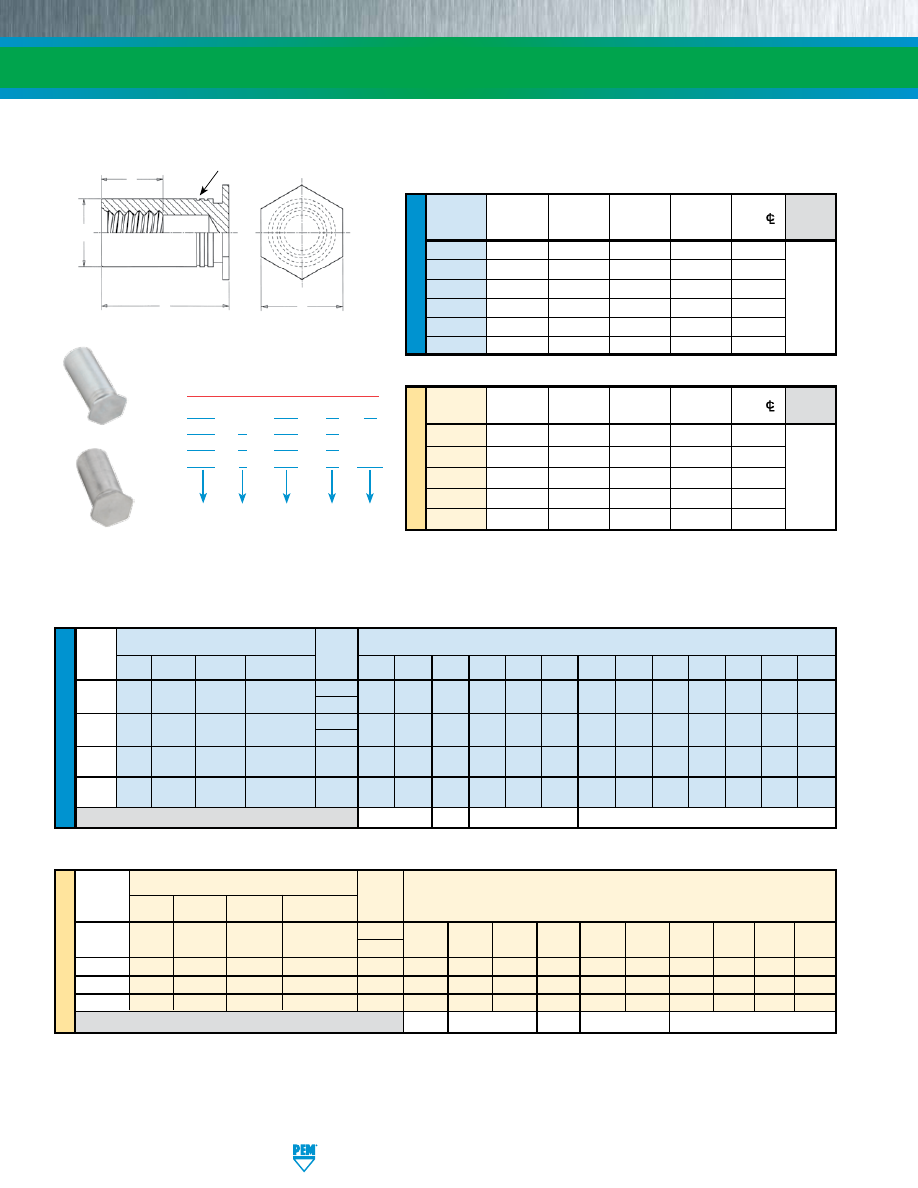
SO-4
PennEngineering • www.pemnet.com
ME
TR
IC
U
NIF
IE
D
ME
TR
IC
U
NIF
IE
D
Min.
Hole Size
Thread Sheet
In Sheet
C H
Min. Dist.
F
Code Thickness +.003
+.000 Nom. Hole
C/
Min.
-.000
-.005 To Edge
440 .040 .166 .165 .187 .23
6440 .040 .213 .212 .250 .27
632 .040 .213 .212 .250 .27
8632 .050 .281 .280 .312 .31
832 .050 .281 .280 .312 .31
032 .050 .281 .280 .312 .31
Type
Thread
Thread
Size x
Stainless
Hardened
Code
Pitch
Steel
Steel
Aluminum
Stainless Steel
M3 x 0.5 BSO BSOS BSOA
BSO4
M3
6 8 10 12 14 16 18 20 22 25
3.5M3
(1)
M3.5 x 0.6
BSO
BSOS
BSOA
BSO4
M3.5
6
8
10
12
14
16
18
20
22
25
M4
x 0.7
BSO
BSOS
BSOA
BSO4
M4
6
8
10
12
14
16
18
20
22
25
M5 x
0.8
BSO
BSOS
BSOA BSO4 M5
6 8 10
12
14
16 18
20
22
25
F Dimension Min.
3.2 4 5 6.5
9.5
Min.
Hole Size
Min. Dist.
Thread
Sheet
In Sheet
C H
Hole
C/
F
Code Thickness +0.08 -0.13 Nom.
To Edge
Min.
M3 1 4.22 4.2 4.8 6
3.5M3 1 5.41 5.39 6.4 6.8
M3.5 1 5.41 5.39 6.4 6.8
M4 1.27 7.14 7.12 7.9 8
M5 1.27 7.14 7.12 7.9 8
SELF-CLINCHING STANDOFFS
All dimensions are in millimeters.
GENERAL DIMENSIONAL DATA
All dimensions are in inches.
THREAD SIZE AND LENGTH SELECTION DATA
All dimensions are in inches.
All dimensions are in millimeters.
Length “L” +0.05 –0.13
(Length Code in millimeters)
TYPES BSO/BSOS/BSOA/BSO4 - BLIND THREADED STANDOFFS
Type
Thread
Thread
Size
Stainless
Hardened
Code
Steel
Steel
Aluminum Stainless Steel .312 .375 .437 .500 .562 .625 .687 .750 .812 .875 .937 1.00 1.062
.112-40
BSO
BSOS BSOA BSO4
440
10 12 14 16 18 20 22 24 26 28 30 32 34
(#4-40)
6440
(1)
.138-32 BSO BSOS BSOA
BSO4
632
10 12 14 16 18 20 22 24 26 28 30 32 34
(#6-32)
8632
(1)
.164-32
BSO BSOS BSOA
BSO4
832 10 12 14 16 18 20 22 24 26 28 30 32 34
(#8-32)
.190-32
BSO BSOS BSOA
BSO4
032 10 12 14 16 18 20 22 24 26 28 30 32 34
(#10-32)
F Dimension Min.
.156 .187
.250
.375
Varies
according
to length.
See length
charts
below.
Varies
according
to length.
See length
charts
below.
BSO – 440 – 12
ZI
BSO
S – 440 – 12
BSO
A – 440 – 12
BSO
4 – 440 – 12 NC*
PART NUMBER DESIGNATION
Material
Code
Thread
Code
Length
Code
Type
Finish
Length “L” +.002 –.005 (Length Code in 32nds of an inch)
Types BSO/BSOS/BSOA
Clinching profile may vary.
H
C
F
L
“Single” or “Two Groove” Registered Trademark
Type BSO4
Installs into stainless steel
(1) Standoffs with thread codes 6440, 8632, and 3.5M3 have a thicker wall to provide more bearing surface for the mating component or panel
reducing the chance of cracking or cutting into the board.
Please contact your local PEM® distributor for availability, minimum quantity, and pricing information.
* NC suffix is required if optional nickel plating (for corrosion resistance) is desired. Otherwise, no suffix is necessary.
pem-html.html
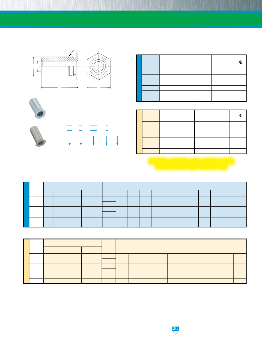
PennEngineering • www.pemnet.com
SO-5
ME
TR
IC
U
NIF
IE
D
ME
TR
IC
U
NIF
IE
D
Min.
Hole Size
Thru-hole Sheet
In Sheet
C H
Min. Dist.
Code Thickness +.003
+.000 Nom. Hole
C/
-.000
-.005 To Edge
4116 .040 .166 .165 .187 .23
6116 .040 .213 .212 .250 .27
6143 .040 .213 .212 .250 .27
8143 .050 .281 .280 .312 .31
8169 .050 .281 .280 .312 .31
8194 .050 .281 .280 .312 .31
Min.
Hole Size
Min. Dist.
Thru-hole
Sheet
In Sheet
C H
Hole
C/
Code Thickness +0.08 -0.13 Nom.
To Edge
43.1 1 4.22 4.2 4.8 6
63.1 1 5.41 5.39 6.4 6.8
63.6 1 5.41 5.39 6.4 6.8
83.6 1.27 7.14 7.12 7.9 8
84.1 1.27 7.14 7.12 7.9 8
85.1 1.27 7.14 7.12 7.9 8
B
Type
Thru-hole
Diameter
Stainless
Hardened Thru-hole
+0.1 -0.08 Steel
Steel
Aluminum
Stainless Steel Code
3.1
SO4
43.1
3 4 6 8 10 12 14 16 18 20
S0 SOS SOA 63.1
(1)
3.6 SO SOS SOA
SO4
63.6
3 4 6 8 10 12 14 16 18 20
83.6
(1)
4.1
SO
SOS SOA SO4 84.1 3 4 6 8 10 12 14 16 18 20
5.1
SO
SOS SOA SO4 85.1 3 4 6 8 10 12 14 16 18 20
B
Type
Thru-hole
Diameter
Stainless
Hardened Thru-hole
+.004 -.003 Steel
Steel
Aluminum
Stainless Steel Code .125 .187 .250 .312 .375 .437 .500 .562 .625 .687 .750
.116 SO SOS SOA
SO4
4116
4 6 8 10 12 14 16 18 20 22 24
6116
(1)
.143 SO SOS SOA SO4
6143
4 6 8 10 12 14 16 18 20 22 24
8143
(1)
.169 SO SOS SOA
SO4
8169 4 6 8 10 12 14 16 18 20 22 24
.194 SO SOS SOA
SO4
8194 4 6 8 10 12 14 16 18 20 22 24
SELF-CLINCHING STANDOFFS
All dimensions are in millimeters.
GENERAL DIMENSIONAL DATA
All dimensions are in inches.
THROUGH-HOLE AND LENGTH SELECTION DATA
All dimensions are in inches.
All dimensions are in millimeters.
TYPES SO/SOS/SOA/SO4 - THROUGH-HOLE UNTHREADED STANDOFFS
Length “L” +.002 –.005 (Length Code in 32nds of an inch)
Length “L” +0.05 –0.13
(Length Code in millimeters)
SO – 4116 – 8
ZI
SO
S – 4116 – 8
SO
A – 4116 – 8
SO
4 – 4116 – 8 NC*
PART NUMBER DESIGNATION
Material
Code
Thru-hole
Code
Length
Code
Type
Finish
Types SO/SOS/SOA
H
L
C B
“Single” or “Two Groove” Registered Trademark
Type SO4
Installs into stainless steel
Clinching profile may vary.
(1) Standoffs with thru-hole codes 6116, 8143, 63.1 and 83.6 have a thicker wall to provide more bearing surface for the mating component or panel
reducing the chance of cracking or cutting into the board.
Please contact your local PEM® distributor for availability, minimum quantity, and pricing information.
* NC suffix is required if optional nickel plating (for corrosion resistance)
is desired. Otherwise, no suffix is necessary.
PEM® through-hole, unthreaded standoffs
are available on special order only.
pem-html.html
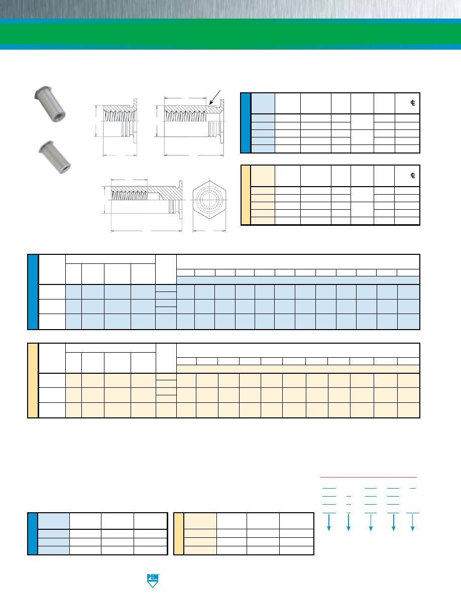
SO-6
PennEngineering • www.pemnet.com
SELF-CLINCHING STANDOFFS
U
NIF
IE
D
ME
TR
IC
Thread
Length “L”
Length “L”
Length “L”
Code
(Style #1)
(Style #2)
(Style #3)
256 / 6256
.090 - .250
.251 - .375
.376 - .750
440 / 6440
.090 - .280
.281 - .450
.451 - .750
632
.120 - .350
.351 - .540
.541 - .750
Thread
Length “L”
Length “L”
Length “L”
Code
(Style #1)
(Style #2)
(Style #3)
M25 / 6M25
2.00 - 6.30
6.32 - 9.50
9.52 - 19.00
M3 / 6M3
2.00 - 7.50
7.52 - 11.00
11.02 - 19.00
M35
3.00 - 8.80
8.82 - 12.80
12.82 - 19.00
THREAD SIZE AND LENGTH SELECTION DATA
All dimensions are in inches.
All dimensions are in millimeters.
LENGTH/STYLE DATA
All dimensions are in inches.
(Length can be specified in .001” increments.)
All dimensions are in millimeters.
(Length can be specified in 0.02 mm increments.)
TYPES TSO/TSOS/TSOA/TSO4 THREADED STANDOFFS FOR SHEETS AS THIN AS .025”/0.63mm
TSO – 440 – 250
ZI
TSO
S – 440 – 250
TSO A – 440 – 250
TSO
4 – 440 – 250 NC*
PART NUMBER DESIGNATION
Material
Code
Thread
Code
Length
Code
Type
Finish
C
F
H
L
Style #3
Types TSO/TSOS/TSOA
(1) Style #1. Thru-threaded.
(2) Style #2. Screw might not pass through unthreaded end. Tapped to minimum full thread depth shown. Incomplete threads on tap may allow screw
to pass through.
(3) Style #3. Blind.
(4) Standoffs with thread codes 6256, 6440, 6M25 and 6M3 have a thicker wall to provide more bearing surface for the mating component or panel
reducing the chance of cracking or cutting into the board.
Please contact your local PEM® distributor for availability, minimum quantity, and pricing information.
ME
TR
IC
U
NIF
IE
D
Min.
Hole Size
C
F Min.
Min. Dist.
Thread
Sheet
In Sheet
+.000
Thread
H
Hole
C/
Code
Thickness +.003 -.000
-.005
Depth
Nom.
To Edge
256 .025 .166 .165
.200
.187 .23
6256 .025 .213 .212 .250 .27
440 .025 .166 .165
.220
.187 .23
6440 .025 .213 .212 .250 .27
632 .025 .213 .212 .270 .250 .27
Min.
Hole Size
F Min.
Min. Dist.
Thread
Sheet
In Sheet
C
Thread
H
Hole
C/
Code
Thickness
+0.08
-0.13
Depth
Nom.
To Edge
M25 0.63 4.22 4.2
5.2
4.8 5.8
6M25 0.63 5.41 5.39 6.4 7.1
M3 0.63 4.22 4.2
6.2
4.8 5.8
6M3 0.63 5.41 5.39 6.4 7.1
M35 0.63 5.41 5.39 7 6.4 7.1
All dimensions are in millimeters.
GENERAL DIMENSIONAL DATA
All dimensions are in inches.
Style #1
C
L
U
NIF
IE
D
Type
Hardened
Thread
Stainless Stainless Thread
.090 .125 .187 .250 .312 .375 .437 .500 .562 .625 .687 .750
Size
Steel Steel Aluminum Steel Code
Length Code (Length “L” without decimal point)
.086-56 TSO TSOS TSOA TSO4
256
090
(1)
125
(1)
187
(1)
250
(1)
312
(2)
375
(2)
437
(3)
500
(3)
562
(3)
625
(3)
687
(3)
750
(3)
(#2-56)
6256
(4)
.112-40
TSO TSOS TSOA TSO4
440
090
(1)
125
(1)
187
(1)
250
(1)
312
(2)
375
(2)
437
(2)
500
(3)
562
(3)
625
(3)
687
(3)
750
(3)
(#4-40)
6440
(4)
.138-32
TSO TSOS TSOA TSO4 632 – 125
(1)
187
(1)
250
(1)
312
(1)
375
(2)
437
(2)
500
(2)
562
(3)
625
(3)
687
(3)
750
(3)
(#6-32)
ME
TR
IC
Thread
Type
Size x
Hardened Thread
Pitch
Stainless Stainless Code
2.00 3.00 4.00 6.00 8.00 10.00 12.00 14.00 16.00 18.00 19.00
Steel Steel Aluminum Steel
Length Code (Length “L” without decimal point)
M2.5 x 0.45 TSO TSOS TSOA TSO4
M25 200
(1)
300
(1)
400
(1)
600
(1)
800
(2)
1000
(3)
1200
(3)
1400
(3)
1600
(3)
1800
(3)
1900
(3)
6M25
(4)
M3 x 0.5 TSO TSOS TSOA TSO4 M3 200
(1)
300
(1)
400
(1)
600
(1)
800
(2)
1000
(2)
1200
(3)
1400
(3)
1600
(3)
1800
(3)
1900
(3)
6M3
(4)
M3.5 x 0.6 TSO TSOS TSOA
TSO4 M35
– 300
(1)
400
(1)
600
(1)
800
(1)
1000
(2)
1200
(2)
1400
(3)
1600
(3)
1800
(3)
1900
(3)
Length “L”
±
.003
For other lengths / thread depth data see chart at bottom of page.
Length “L”
±
0.08
For other lengths / thread depth data see chart at bottom of page.
Clinching profile may vary.
Style #2
C
F
L
“Single” or “Two Groove”
Registered Trademark
Type TSO4
Installs into stainless steel
* NC suffix is required if optional
nickel plating (for corrosion
resistance) is desired. Otherwise,
no suffix is necessary.
pem-html.html
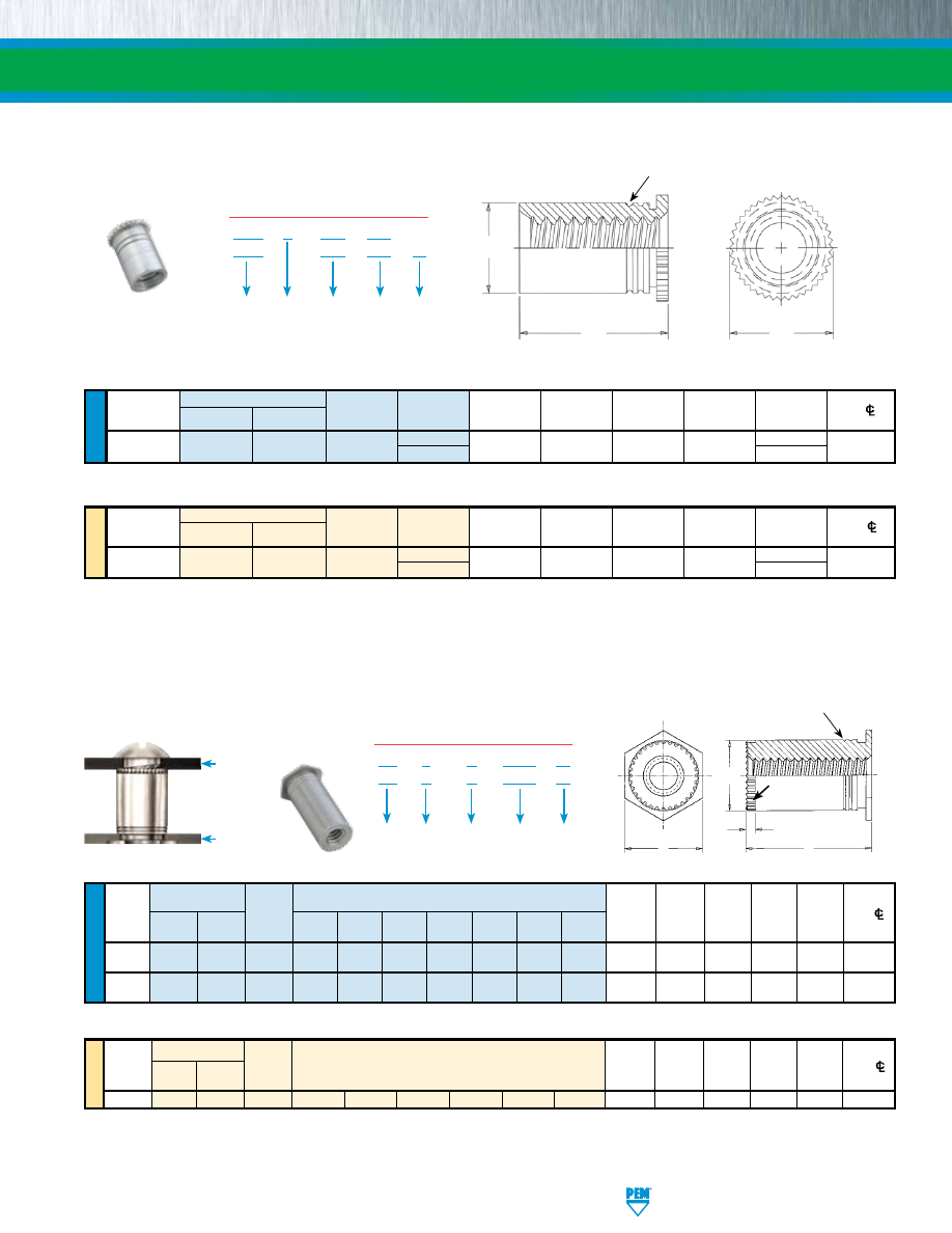
PennEngineering • www.pemnet.com
SO-7
SELF-CLINCHING STANDOFFS
ME
TR
IC
U
NIF
IE
D
Type
Hole Size
L
(1)
Min. Dist.
Thread
Stainless
Thread
Length
Sheet
In Sheet
C
H
+.002
Hole
C/
Size
Steel Steel
Code
Code
Thickness
+.003 -.000
Max.
Nom.
-.005
To Edge
.112-40
DSOS DSO
440
250
.037 - .250
.166
.165
.194
.250
.126
(#4-40)
275
.275
Thread
Type
Hole Size
C L
(1)
Min. Dist.
Size x
Stainless
Thread
Length
Sheet
In Sheet
Max. H +0.05 Hole
C/
Pitch
Steel Steel Code Code Thickness +0.08
Nom. -0.13 To Edge
M3 x 0.5
DSOS
DSO
M3
6.35
0.94 - 6.35
4.22
4.2
4.92
6.35
3.2
7 7
(1) Available in other lengths on special order.
Please contact your local PEM® distributor for availability, minimum quantity, and pricing information.
All dimensions are in inches.
All dimensions are in millimeters.
TYPES DSOS/DSO THREADED STANDOFFS - FOR CLOSE-TO-EDGE APPLICATIONS
ME
TR
IC
U
NIF
IE
D
Length “L” +.010 -.000
(2)
Min. Hole
Thread
Type
Thread
(Length Code is in 32nds of an inch) Sheet
Size In
C
H
P
Min. Dist.
Size Code Thick- Sheet +.000 ±.005
Nom. Hole
C/L
Stainless
.125 .187 .250 .312 .375 .437 .500
ness
+.003
–.005
To Edge
Steel
Aluminum
–.000
.112-40
SOSG
SOAG
6440 4 6 8 10 12 14 16 .040 .213 .212 .250 .030 .27
(#4-40)
.138-32 SOSG SOAG 8632 4 6 8 10 12 14 16 .050 .281 .280 .312 .030 .31
(#6-32)
Thread
Min. Hole
Size x
Type
Thread
Sheet
Size In
C
H
P
Min. Dist.
Pitch Stainless
Code
Thick-
Sheet
–0.13
±0.25
Nom.
Hole
C/L
Steel
Aluminum
ness
+0.08
To Edge
M3 x 0.5
SOSG
SOAG
3.5M3
3
4
6
8
10
12
1
5.4
5.39
6.4
0.76
6.8
(2) For special lengths greater than .500” / 12 mm, Types SOSG and SOAG are blind threaded.
TYPES SOSG/SOAG GROUNDING STANDOFFS
All dimensions are in inches.
All dimensions are in millimeters.
Metal
PC Board
or plastic
DSO S – 440 – 250
DSO – 440 – 250
ZI
PART NUMBER DESIGNATION
Material
Code
Thread
Code
Length
Code
Type
Finish
SO
S
G – 6440 – 10
SO
A
G – 6440 – 10
PART NUMBER DESIGNATION
Material
Code
Thread
Code
Length
Code
Type
Gripping
Length “L” +0.25
(2)
(Length Code is in millimeters)
Clinching profile may vary.
Clinching profile may vary.
C
L
H
“Two Groove” Registered Trademark
H
L
P
C
Gripping Teeth
“Two Groove” Registered Trademark
pem-html.html
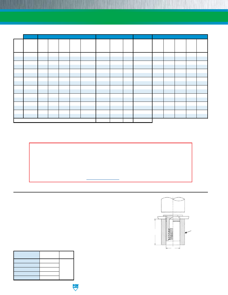
SO-8
PennEngineering • www.pemnet.com
SELF-CLINCHING STANDOFFS
Threads
(1)
Fastener Materials
Standard Finishes
Optional Finish
For Use In Sheet Hardness:
(4)
Internal, ASME
Non-heat
300
Zinc Plated
Passivated
Electroless Nickel
B1.1, 2B
Hardened
Treated
Series
Hardened
5µm,
and/or Tested
over Copper over
HRB 88 /
HRB 80 /
HRB 70 /
HRB 60 /
HRB 50 /
Type
ASME
Carbon
Carbon
Aluminum Stainless
400 Series
Colorless
Per ASTM
No
Nickel Strike
HB 183
HB 150
HB 125
HB 107
HB 89
B1.13M, 6H
Steel
Steel
Steel
Stainless Steel
(2)
A380
Finish
Per ASTM B733 (2) (3)
or Less
or Less
or Less
or Less
or Less
SO
• • •
•
SOA
• •
•
•
SOS
•
• •
•
SO4
• • • • •
BSO
• • •
•
BSOA
• •
•
•
BSOS
•
• •
•
BSO4
• • • • •
TSO
• •
•
•
TSOS
•
• •
•
TSOA
• •
•
•
TSO4
• • • • •
DSO
• • •
•
DSOS
•
• •
•
SOAG
• •
•
•
SOSG
•
• •
•
Part Number Codes For Finishes
ZI
None
None
NC
TYPES SO/SOS/SOA/SO4/BSO/BSOS/BSOA/BSO4
1.
Prepare properly sized mounting hole in sheet. Do not perform any
secondary operation such as deburring.
2.
Insert standoff through mounting hole (preferably the punch side) of
sheet and into anvil as shown in drawing.
3.
With installation punch and anvil surfaces parallel, apply only enough
squeezing force to embed the standoff’s head flush in the sheet.
Drawing at right shows suggested tooling for applying these forces.
C*
L* Min.
PUNCH
+.004” to +.007” /
+0.1 mm to +0.18 mm
ANVIL
INSTALLATION
(1) Where applicable.
(2) See PEM Technical Support section of our web site for related plating standards and specifications.
(3) Not stocked, available on special order. Minimum quantities apply. Contact your local PEM distributor for details.
(4) HRB - Hardness Rockwell “B” Scale. HB - Hardness Brinell.
MATERIAL AND FINISH SPECIFICATIONS
Thread
Anvil Part
Punch Part
Code
Number Number
440/M2/M2.5/M3 970200487300
632/6440/3.5M3/M3.5 970200012300
832/8632/M4 970200013300
975200048
032/M5 970200013300
0420/M6 970200393300
PEMSERTER® Installation Tooling
*See pages 3 & 4
for “C” and “L”.
A NOTE ABOUT FASTENERS FOR STAINLESS STEEL PANELS
In order for self-clinching fasteners to work properly, the fastener must be harder than the sheet into which it is being installed. In
the case of stainless steel panels, fasteners made from 300 Series Stainless Steel do not meet this hardness criteria. It is for this
reason that 400 series fasteners are offered (Types SO4, BSO4, and TSO4). However, while these 400 Series fasteners install and
perform well in 300 Series stainless sheets they should not be used if the end product:
•
Will be exposed to any appreciable corrosive environment (unless finished with optional nickel plating).
•
Requires non-magnetic fasteners.
•
Will be exposed to any temperatures above 300˚F (149˚C)
If any of the these are issues, please contact
techsupport@pemnet.com
for other options.
pem-html.html
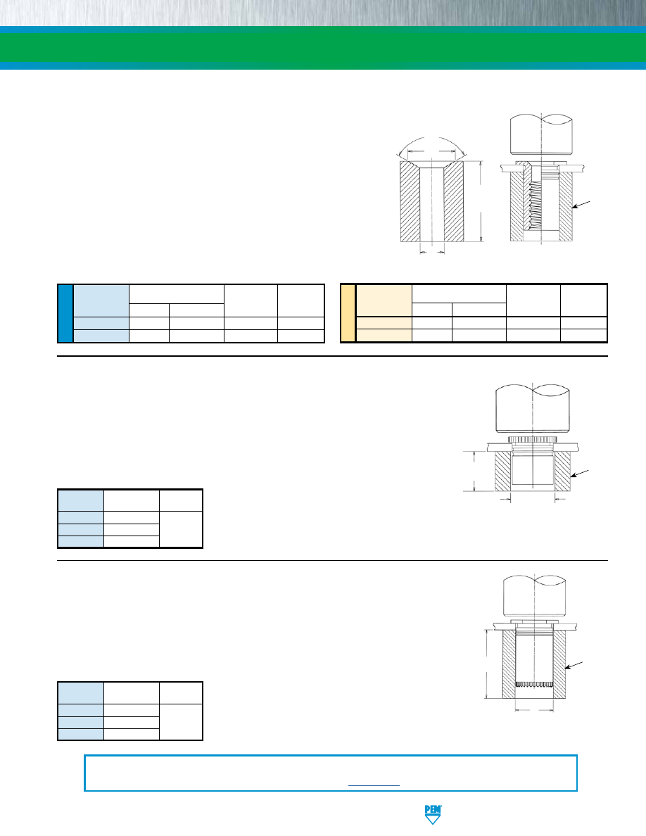
PennEngineering • www.pemnet.com
SO-9
SELF-CLINCHING STANDOFFS
REQUIRED INSTALLATION
ANVIL FOR SHEETS BELOW
.032” / 0.81 MM
L* Min.
B
120˚
PUNCH
ANVIL
TYPES DSOS/DSO
1.
Prepare properly sized mounting hole in sheet.
Do not perform any secondary
operations such as deburring.
2.
Insert fastener through mounting hole (preferably the punch side) and into
anvil as shown in drawing.
3.
With installation punch and anvil surfaces parallel, apply only enough
squeezing force to embed the standoff’s head flush in the sheet.
TYPES TSO/TSOS/TSOA/TSO4
1.
Prepare properly sized mounting hole in sheet. Do not perform
any secondary operation such as deburring.
2.
Insert standoff through mounting hole (preferably the punch
side) of sheet and into anvil as shown in drawing.
3.
With installation punch and anvil surfaces parallel, apply only
enough squeezing force to embed the standoff’s head flush in
the sheet. Drawing at right shows required installation anvil
for sheet thickness of .025” to .032” / 0.63 mm to 0.81 mm. A
chamfered anvil is not required for sheets over .032” / 0.81 mm.
INSTALLATION
ANVIL
L* Min.
PUNCH
*See page 7 for
“D” and “L”.
U
NIF
IE
D
Anvil Part No.
Thread
For Sheets
Punch Part
Code
B
Anvil Part No.
Over .032”
Number
256/440
.187 - .194
8003291
970200487300
975200048
6256/6440/632
.250 - .257
8003292
970200012300
975200048
Thread
Anvil Part
Punch Part
Code
Number
Number
440/M3 970200487300
6440/3.5M3 970200012300 975200048
8632 970200013300
PEMSERTER® Installation Tooling
PEMSERTER® Installation Tooling
C*
Anvil Dimensions (in.)
For Sheets Below .032”
ME
TR
IC
Anvil Part No.
Thread
For Sheets
Punch Part
Code
B
Anvil Part No.
Over 0.81 mm
Number
M2.5/M3
4.75 - 4.93
8003291
970200487300
975200048
6M25/6M3/M35
6.35 - 6.53
8003292
970200012300
975200048
Anvil Dimensions (mm)
For Sheets Below 0.81 mm
+.001” to +.004” /
+0.03 mm to +0.1 mm
C*
PUNCH
ANVIL
+.004” to +.007” /
+0.1 mm to +0.18 mm
*See page 7 for “C”
and “L”.
TYPES SOSG/SOAG
1.
Prepare properly sized mounting hole in sheet.
Do not perform any secondary
operations such as deburring.
2.
Insert fastener through mounting hole (preferably the punch side) and into
anvil as shown in drawing.
3.
With installation punch and anvil surfaces parallel, apply only enough
squeezing force to embed the standoff’s head flush in the sheet.
Thread
Anvil Part
Punch Part
Code
Number
Number
440/M3 970200487300
6440/3.5M3 970200012300 975200048
8632 970200013300
PEMSERTER® Installation Tooling
C*
+.004” to +.007” /
+0.1 mm to +0.18 mm
L* Min.
*See page 6 for “C”
and “L”.
INSTALLATION NOTES
•
For best results we recommend using a PEMSERTER® press for installation of PEM standoffs. Please check our website for more information.
•
Visit the Animation Library on our website to view the installation process
for this product
.
pem-html.html
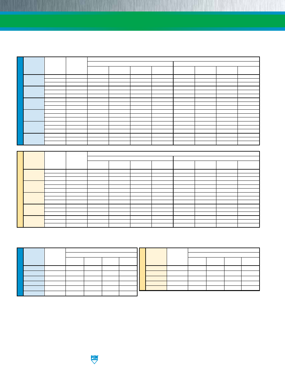
SO-10
PennEngineering • www.pemnet.com
ME
TR
IC
U
NIF
IE
D
Max. Rec.
Test Sheet Material
Thread Standoff Tightening
.060” 5052-H34 Aluminum
.060” Cold-rolled Steel
Code Material
Torque For
Mating Screw
Installation
Pushout
Torque-out
Pull-thru
Installation
Pushout
Torque-out
Pull-thru
(in. lbs.)
(lbs.)
(lbs.)
(in. lbs.)
(2)
(lbs.)
(2)
(lbs.)
(lbs.)
(in. lbs.)
(2)
(lbs.)
(2)
Steel 4.75 1100 160 11 280 2200 225 19 330
440
Stainless Steel
3.8
1100
160
11
224
2200
225
19
264
Aluminum
2.85
1100
160 11 168 – – – –
Steel 4.75 1700 300 25 310 3300 420 35 380
6440
Stainless Steel
3.8
1700
300
25
248
3300
420
35
304
Aluminum
2.85
1700
300
25
186 – – – –
Steel 8.75 1700 300 25 310 3300 420 35 380
632
Stainless Steel
7
1700
300
25
248
3300
420
35
304
Aluminum
5.25
1700
300
25
186 – – – –
Steel 8.75 2400 400 45 580 4000 560 75 700
8632
Stainless Steel
7
2400
400
45
464
4000
560
75
560
Aluminum
5.25
2400
400
45
248 – – – –
Steel 18 2400 400 45 580 4000 560 75 700
832
Stainless Steel
14.4
2400
400
45
464
4000
560
75
560
Aluminum
11
2400
400
45
348 – – – –
Steel 32 2400 400 45 580 4000 560 75 700
032
Stainless Steel
25.6
2400
400
45
464
4000
560
75
560
Aluminum
19
2400
400
45
348 – – – –
Max. Rec.
Test Sheet Material
Thread Standoff Tightening
1.5 mm 5052-H34 Aluminum
1.5 mm Cold-rolled Steel
Code Material
Torque For
Mating Screw
Installation
Pushout
Torque-out
Pull-thru
Installation
Pushout
Torque-out
Pull-thru
(N•m) (kN) (N) (N•m)
(2)
(N)
(2)
(kN) (N) (N•m)
(2)
(N)
(2)
Steel 0.55 4.9 710 1.24 1245 9.8 1000 2.15 1465
M3
Stainless Steel
0.44
4.9
710
1.24
996
9.8
1000
2.15
1172
Aluminum 0.33 4.9 710 1.24 747
– – – –
Steel 0.55 7.6 1330 2.82 1375 14.7 1860 3.95 1690
3.5M3
Stainless Steel
0.44
7.6
1330
2.82
1100
14.7
1860
3.95
1352
Aluminum
0.33
7.6
1330
2.82
825 – – – –
Steel 0.91 7.6 1330 2.82 1375 14.7 1860 3.95 1690
M3.5
Stainless Steel
0.73
7.6
1330
2.82
1100
14.7
1860
3.95
1352
Aluminum
0.55
7.6
1330
2.82
825 – – – –
Steel 2 10.7 1780 5.08 2575 17.8 2490 8.47 3110
M4
Stainless Steel
1.6
10.7
1780
5.08
2060
17.8
2490
8.47
2488
Aluminum
1.2 10.7
1780
5.08
1545 – – – –
Steel 3.6 10.7 1780 5.08 2575 17.8 2490 8.47 3110
M5
Stainless Steel
2.88
10.7
1780
5.08
2060
17.8
2490
8.47
2488
Aluminum
2.16
10.7
1780
5.08
1545 – – – –
TYPES SO/SOS/SOA/BSO/BSOS/BSOA
(1) Published installation forces are for general reference. Actual set-up and confirmation of complete installation should be made by observing
proper seating of fastener as described in the installation steps. Other performance values reported are averages when all proper
installation parameters and procedures are followed. Variations in mounting hole size, sheet material, and installation procedure may affect
performance. Performance testing this product in your application is recommended. We will be happy to provide technical assistance and/
or samples for this purpose.
(2) Joint failure in torque-out and pull-thru will depend on the strength and type of screw being used. In some cases the failure will be in the screw and
not in the self-clinching standoff. Please contact our Applications Engineering group with any questions.
SELF-CLINCHING STANDOFFS
PERFORMANCE DATA
(1)
ME
TR
IC
U
NIF
IE
D
Max. Rec.
Test Sheet Material
Thread
Tightening
.050” 300 Series Stainless Steel
Code
Torque For
Mating Screw
Installation
Pushout
Torque-out
Pull-thru
(in. lbs.)
(lbs.)
(lbs.)
(in. lbs.)
(2)
(lbs.)
(2)
440
4.75 5500 336 17 600
6440 4.75 9500 647 30 680
632
8.75 9500 647 30 680
8632
8.75
10500
900
71
1392
832
18 10500 900 71 1517
032
32 10500 900 71 1368
TYPES SO4/BSO4
Max. Rec.
Test Sheet Material
Thread
Tightening
1.3 mm 300 Series Stainless Steel
Code
Torque For
Mating Screw
Installation
Pushout
Torque-out
Pull-thru
(N•m) (kN) (N) (N•m)
(2)
(N)
(2)
M3
0.55
24.5
1493
2.36
2650
3.5M3 0.55 42.3 2877 3.06 3025
M3.5
0.91 42.3 2877 3.06 3025
M4
2
46.7 4003 8.89 6458
M5
3.6
46.7 4003 8.89 6226
pem-html.html
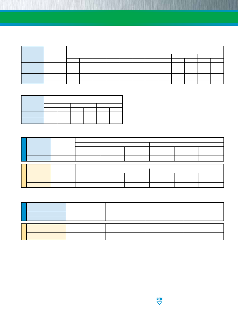
PennEngineering • www.pemnet.com
SO-11
SELF-CLINCHING STANDOFFS
ME
TR
IC
U
NIF
IE
D
TYPES DSOS/DSO
(1) Published installation forces are for general reference. Actual set-up and confirmation of complete installation should be made by observing
proper seating of fastener as described in the installation steps. Other performance values reported are averages when all proper
installation parameters and procedures are followed. Variations in mounting hole size, sheet material, and installation procedure may affect
performance. Performance testing this product in your application is recommended. We will be happy to provide technical assistance and/
or samples for this purpose.
(2) Joint failure in torque-out and pull-thru will depend on the strength and type of screw being used. In some cases the failure will be in the screw and
not in the self-clinching standoff. Please contact our Applications Engineering group with any questions.
Max. Rec.
Test Sheet Material
Tightening
.040” 5052-H34 Aluminum
.040” Cold-rolled Steel
Thread
Torque For
Code
Mating Screw
Installation
Pushout
Torque-out
Installation
Pushout
Torque-out
(in. lbs.)
(lbs.)
(lbs.)
(in. lbs.)
(2)
(lbs.)
(lbs.)
(in. lbs.)
(2)
440 3.8 1000 50 10 1300 75 10
Max. Rec.
Test Sheet Material
Tightening
1 mm 5052-H34 Aluminum
1 mm Cold-rolled Steel
Thread
Torque For
Code
Mating Screw
Installation
Pushout
Torque-out
Installation
Pushout
Torque-out
(N•m)
(kN) (N) (N•m)
(2)
(kN) (N) (N•m)
(2)
M3 0.44 4.5 223 1.1 5.8 334 1.1
PERFORMANCE DATA
(1)
U
NIF
IE
D
Thread
Test Sheet Thickness and
Installation
Pushout
Torque-out
Code
Test Sheet Material
(lbs.)
(lbs.)
(in. lbs.)
(2)
6440
.064” 5052-H34 Aluminum 1700
300
25
8632
.064” 5052-H34 Aluminum 1700
400
45
TYPES SOSG/SOAG
ME
TR
IC
Thread
Test Sheet Thickness and
Installation
Pushout
Torque-out
Code
Test Sheet Material
(kN)
(N)
(N•m)
(2)
3.5M3
1.6 mm 5052-H34 Aluminum
7.6
1330
2.82
Test Sheet Material
Standoff “C”
Standoff
.025” / 0.64 mm 5052-H34 Aluminum
.025” / 0.64 mm Cold-rolled Steel
Dimension
Material
Installation
Pushout
Torque-out
(2)
Installation
Pushout
Torque-out
(2)
(lbs.)
(kN)
(lbs.)
(N)
(in. lbs.)
(N•m)
(lbs.)
(kN)
(lbs.)
(N)
(in. lbs.)
(N•m)
.165” /
Steel
1500 6.7 70 311 6 0.68 2000 8.9 100 445 9
1
4.2 mm
Stainless Steel
1500
6.7
70
311
6
0.68
2000
8.9
100
445
9
1
Aluminum 1500 6.7 70 311 6 0.68 — — — — — —
.212” /
Steel
1800 8 90 400 11 1.24 2500 11.1 150 667 15 1.7
5.39 mm
Stainless Steel
1800
8
90
400
11
1.24
2500
11.1
150
667
15
1.7
Aluminum 1800 8 90 400 11 1.24 — — — — — —
TYPES TSO/TSOS/TSOA
Standoff “C”
Dimension
Installation
Pushout
Torque-out
(2)
(lbs.) (kN) (lbs.) (N) (in.
lbs.) (N•m)
.165” / 4.2 mm
5700
25.4
125
555
13
1.5
.212” / 5.39 mm
6800
30.3
160
710
22
2.5
Test Sheet Material
.025” / 0.64 mm 300 series stainless steel
TYPE TSO4
pem-html.html
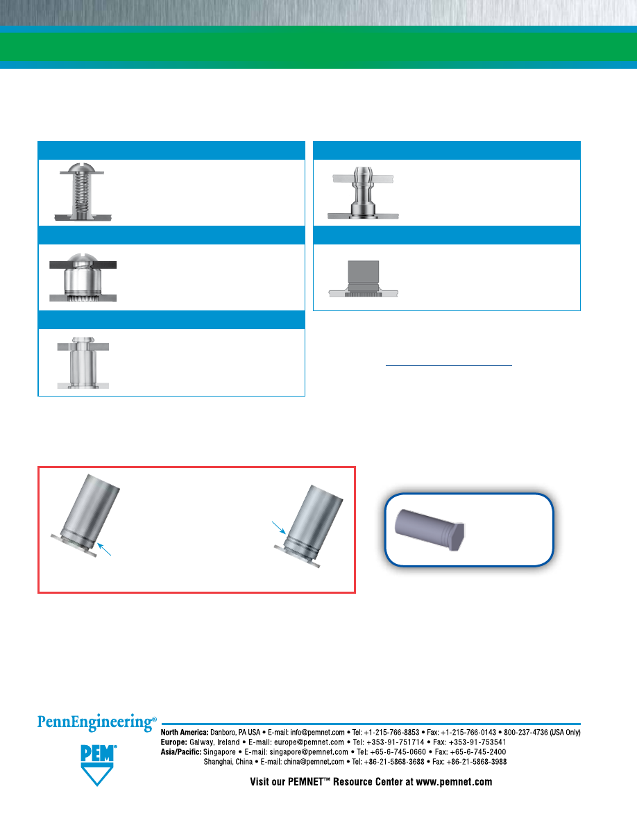
SO-12
SELF-CLINCHING STANDOFFS
If you require a standoff which we do not offer in this bulletin, please contact us. We will be happy to work with you to satisfy
your special need. For other types of standard PEM® brand standoffs and spacers see:
Single Groove
(registered trademark)
Parts that install into
stainless steel
Two Groove
(registered trademark)
On actual parts, location of grooves on barrel may be different than shown in photo.
Technical support e-mail: techsupport@pemnet.com
All PEM® products meet our stringent quality standards. If you require additional industry or other specific quality certifications, special procedures and/or part
numbers are required. Please contact your local sales office or representative for further information.
Regulatory compliance information is available in Technical Support section of our website. Specifications subject to change without notice. See our website for
the most current version of this bulletin.
© 2016 PennEngineering.
For more information on how to use
PEM® self-clinching standoffs, see Tech Sheet
“
PEM®-Ref/Standoff Basics
”
on our web site.
Fastener drawings
and models are
available at
www.pemnet.com
Bulletin CH
PEM® concealed-head standoffs.
Bulletin SSA
PEM® brand SNAP-TOP® standoffs.
Bulletin SK
PEM® KEYHOLE® standoffs.
PEM® brand microPEM® standoffs.
Bulletin K
PEM® broaching and surface
mount standoffs for printed
circuit boards.
Bulletin MPF
pem-html.html
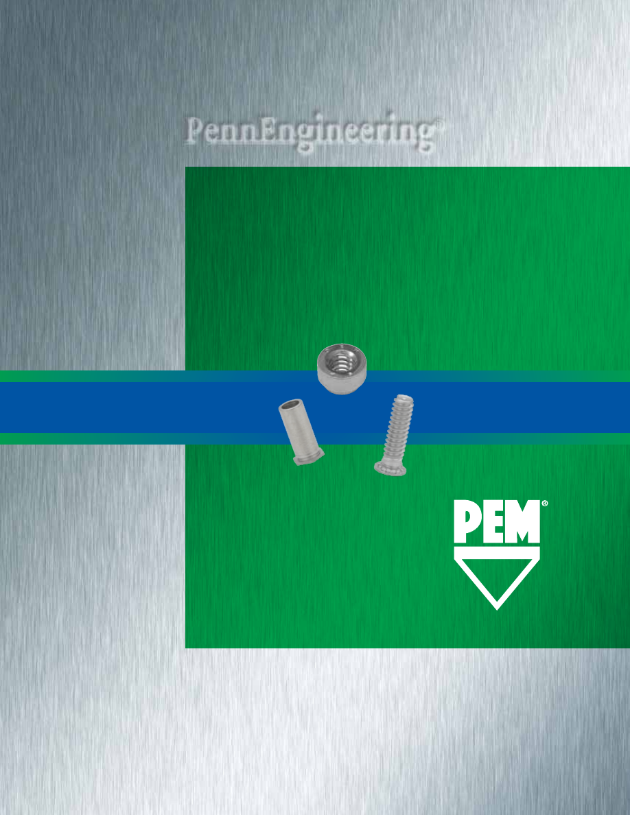
416
R
e v
517
FASTeNeRS FOR USe IN
STAINLeSS STeeL SHeeTS
BULLeTIN
SS
pem-html.html
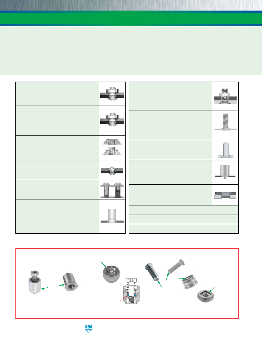
SS-2
PennEngineering • www.pemnet.com
One of the very basics of self-clinching is that the fastener must always be harder than the host sheet to ensure proper and
permanent installation. This is particularly challenging when installing fasteners into stainless steel sheets. Therefore we
have developed this line of specially hardened stainless steel fasteners for installation into stainless steel.
Refer to “Dos
and Don’ts” on page 24 for further information.
Fasteners made from precipitation hardened grade stainless including A286 stainless are particularly useful in applications
such as outdoor equipment, medical devices and chemical and food processing equipment or anywhere corrosive element
exposure is possible.
FASTENERS FOR USE IN STAINLESS STEEL SHEETS
Types FH4™ and FHP™
offer
externally
threaded attachment points in two stainless
materials, depending on the level of corrosion
resistance required. (See page 24 for other
non-clinching stud solutions) -
PAGE 10
SGPC
™
Swaging Collar Studs
can install
into most panel material and accommodate
multiple panels as long as the total thickness
does not exceed the maximum sheet thickness
-
PAGE 11
Type TP4™
pins provide an
unthreaded
solution for a wide range of positioning, pivot
and alignment applications. -
PAGE 12
Type PFC4™
provides a self-clinching, tool
only,
captive screw solution for stainless
steel sheets. (See page 24 for other non-
clinching captive screw solutions) -
PAGE 13
Type SFP™
SpotFast
®
fasteners provide
a solution for
flush “face-on-face” sheet
attachment in stainless steel -
PAGE 14
Type SP™ PEM 300
®
nuts provide
strong
load-bearing internal threads in stainless
steel sheets as thin as .030”/0.8mm -
PAGE 3
Type SMPP™
nuts install into stainless steel
sheets as thin as .025”/0.64mm. Reduced outer
dimensions and thinner sheet capabilities
compared to Type SP thread sizes -
PAGE 4
Types A4™ and LA4™
internally threaded
floating nuts allow for
mating hole
misalignment and locking threads if
desired. -
PAGE 5
Type F4™
fasteners are ideal for
flush
applications where a stainless steel sheet
requires load-bearing threads -
PAGE 6
Types SO4™ and BSO4™
standoffs provide
internally threaded fasteners for
stacking or
spacing applications -
PAGES 7 and 8
Type TSO4™
Through hole threaded standoffs
for clinching into thinner sheets than
Type SO4. Install into sheets as thin as
.025”/0.63mm. Also, threaded at the barrel
end minimizing length of screw required -
PAGE 9
Material and finish specifications -
PAGE 15
Installation -
PAGES 16 - 20
Performance data -
PAGES 21 - 23
For more information on these and other PEM® products, visit our PEMNET ™ Resource Center at
www.pemnet.com
To be sure that you are getting genuine PEM® brand fasteners, look for the unique PEM® product markings and identifiers.
On actual parts, location of groove on fastener may be different than shown in photo.
Single Groove
(Registered
Trademark)
PEM
®
Stamp
(Registered
Trademark)
Blue Retain-
ing Ring
(Trademark)
Dimple
(Registered
Trademark)
PEM
®
Double
Squares
(Registered
Trademark)
pem-html.html
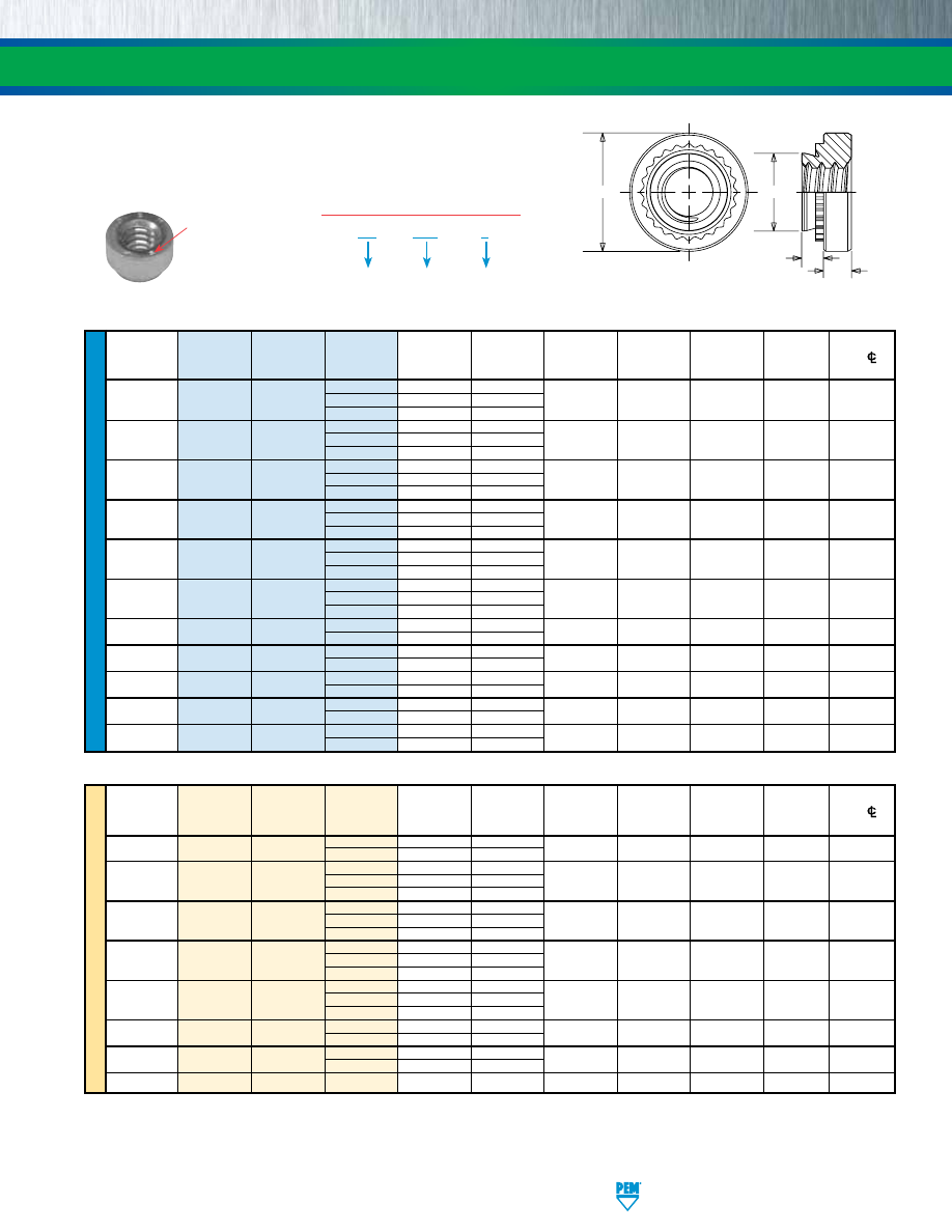
PennEngineering • www.pemnet.com
SS-3
U
NIF
IE
D
A
Rec.
Hole
Size
Min.
Dist.
Thread
Type
Thread
Shank
(Shank)
Min. Sheet
In Sheet
C
E
T
Hole
C/L
Size
Code
Code
Max.
Thickness
+.003 -.000
Max.
±.010
±.010
To Edge (1)
.086-56
0 .030 .030
(#2-56) SP 256 1 .038 .040 .166 .165 .250 .070 .19
2
.054
.056
.112-40
0 .030 .030
(#4-40) SP 440 1 .038 .040 .166 .165 .250 .070 .19
2
.054
.056
.138-32
0 .030 .030
(#6-32) SP 632 1 .038 .040 .1875 .187 .280 .070 .22
2
.054
.056
.164-32
0 .030 .030
(#8-32) SP 832 1 .038 .040 .213 .212 .310 .090 .27
2
.054
.056
.190-24
0 .030 .030
(#10-24) SP 024 1 .038 .040 .250 .249 .340 .090 .28
2 .054 .056
.190-32
0 .030 .030
(#10-32) SP 032 1 .038 .040 .250 .249 .340 .090 .28
2
.054
.056
.250-20
SP 0420
1 .054 .056
.344 .343 .440 .170 .34
(1/4-20) 2 .087 .090
.313-18
SP 0518
1 .054 .056
.413 .412 .500 .230 .38
(5/16-18)
2 .087 .090
.313-24
SP 0524
1 .054 .056
.413 .412 .500 .230 .38
(5/16-24)
2 .087 .090
.375-16
SP 0616
1 .087 .090
.500 .499 .560 .270 .44
(3/8-16) 2 .120 .125
.375-24
SP 0624
1 .087 .090
.500 .499 .560 .270 .44
(3/8-24) 2 .120 .125
•
After installation, reverse side of sheet remains flush and smooth.
•
For use in stainless steel sheets HRB 90 / HB 192 or less.
•
Corrosion resistance similar to 300 series stainless steel.
(1) To minimize sheet distortion and maximize product performance, use a centerline-to-edge value greater or equal to the value specified.
The PEM 300®
Identification
Marks
FASTENERS FOR USE IN STAINLESS STEEL SHEETS
All dimensions are in inches.
All dimensions are in millimeters.
SP – 440 – 2
PART NUMBER DESIGNATION
Type and
Material
Thread
Code
Shank Code
TYPE SP™ PEM 300® SELF-CLINCHING NUTS
The increased hardness of stainless steel panels requires careful consideration when installing self-clinching fasteners.
Refer to Dos and Don’ts on page 24 for further information.
ME
TR
IC
Thread
A
Rec.
Hole
Size
Min.
Dist.
Size x
Type
Thread
Shank
(Shank)
Min. Sheet
In Sheet
C
E
T
Hole
C/L
Pitch
Code
Code
Max.
Thickness
+0.08
Max.
±0.25
±0.25
To Edge (1)
M2 x 0.4
SP
M2
1 0.97 1
4.22 4.2 6.35 1.5 4.8
2
1.38
1.4
0 0.77 0.8
M2.5 x 0.45
SP
M2.5
1
0.97
1
4.22
4.2
6.35
1.5
4.8
2
1.38
1.4
0 0.77 0.8
M3 x 0..5
SP
M3
1
0.97
1
4.22
4.2
6.35
1.5
4.8
2
1.38
1.4
0
0.77
0.8
M4 x 0.7 SP M4 1 0.97 1 5.41 5.38 7.87 2 6.9
2
1.38
1.4
0
0.77
0.8
M5 x 0.8
SP
M5
1
0.97
1
6.35
6.33
8.64
2
7.1
2
1.38
1.4
M6 x 1
SP
M6
1 1.38 1.4
8.75 8.73 11.18 4.08 8.6
2
2.21
2.29
M8 x 1.25
SP
M8
1 1.38 1.4
10.5 10.47 12.7 5.47 9.7
2
2.21
2.29
M10 x 1.5
SP
M10
1
2.21
2.29
14
13.97
17.35
7.48
13.5
E
C
A
T
Clinching profile may vary.
pem-html.html
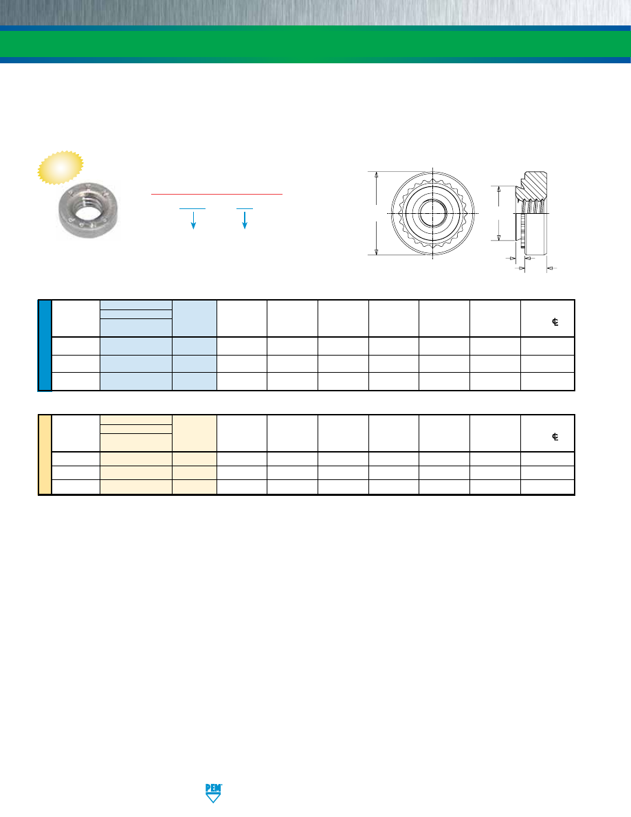
SS-4
PennEngineering • www.pemnet.com
FASTENERS FOR USE IN STAINLESS STEEL SHEETS
•
Installs into stainless steel sheets as thin as .025”/0.64mm.
•
Corrosion resistance similar to 300 series stainless steel.
•
Reduced outer dimensions and thinner sheet capabilities compared to Type SP thread sizes.
•
Recommended for use in stainless steel sheets HRB 90 / HB 192 or less.
TYPE SMPP™ SELF-CLINCHING NUTS
C
A
T
E
Clinching profile may vary.
U
NIF
IE
D
Type
Fastener Material
A
Hole Size
Min. Dist.
Thread
Hardened
Thread
(Shank)
Min. Sheet
In Sheet
C
E
T
Hole
CL
Size
Stainless Steel Code Max. Thickness
+.003 –.000
Max.
±.010
±.010
To Edge
.086-56
SMPP
256 .024 .025 .136 .135 .220 .065 .16
(#2-56)
.112-40
SMPP
440 .024 .025 .166 .165 .220 .065 .20
(#4-40)
.138-32
SMPP
632 .024 .025 .187 .186 .252 .065 .22
(#6-32)
All dimensions are in inches.
ME
TR
IC
Type
Thread
Fastener Material
A
Hole Size
Min. Dist.
Size x
Hardened
Thread
(Shank)
Min. Sheet
In Sheet
C
E
T
Hole
CL
Pitch
Stainless Steel Code Max. Thickness
+0.08
Max.
±0.25
±0.25
To Edge
M2.5 x 0.45
SMPP
M2.5
0.61
0.64
3.8
3.79
5.6
1.4
3.9
M3 x 0.5
SMPP
M3
0.61
0.64
4.24
4.22
5.6
1.4
5.1
M3.5 x 0.6
SMPP
M3.5
0.61
0.64
4.75
4.73
6.4
1.4
5.5
All dimensions are in millimeters.
SMPP – 440
PART NUMBER DESIGNATION
Type and
Material
Thread
Code
NEW
The increased hardness of stainless steel panels requires careful consideration when installing self-clinching fasteners.
Refer to Dos and Don’ts on page 24 for further information.
pem-html.html
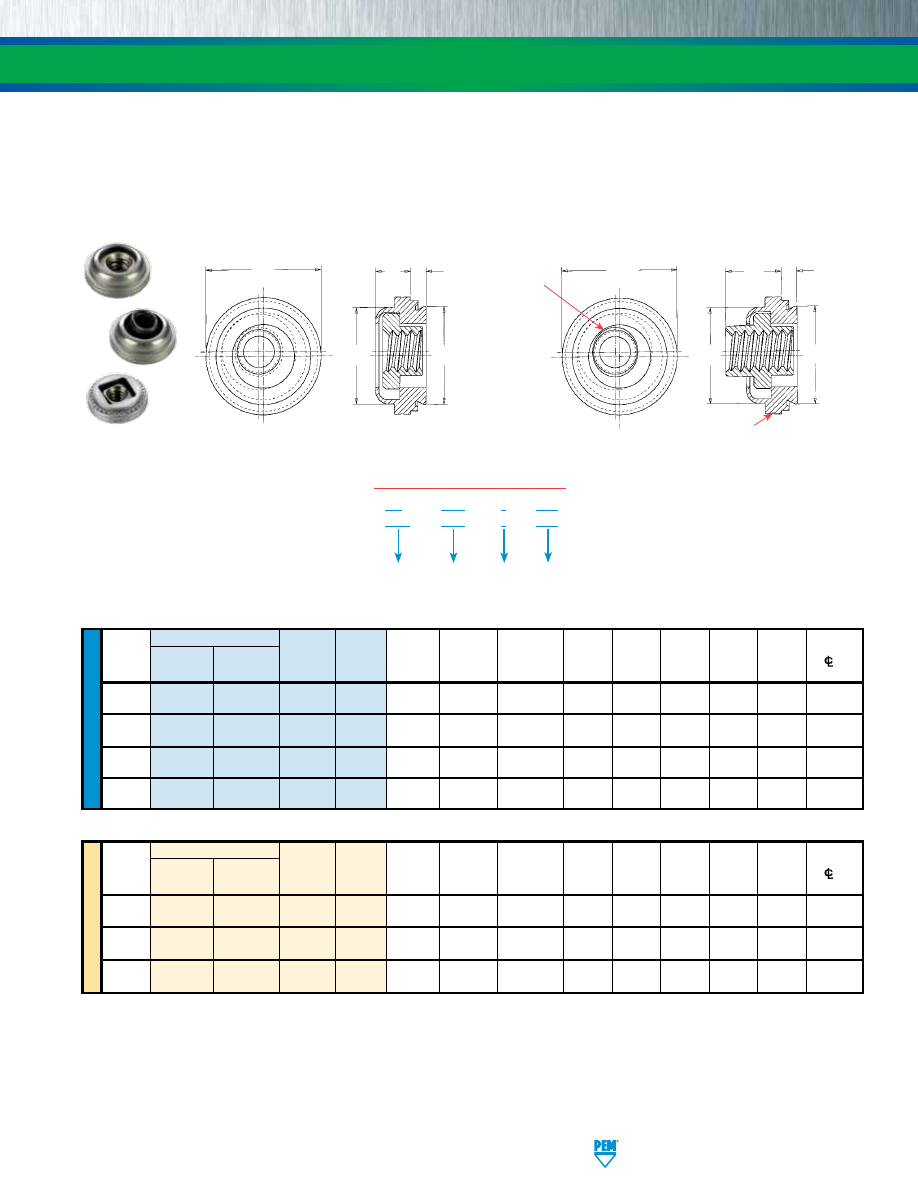
PennEngineering • www.pemnet.com
SS-5
FASTENERS FOR USE IN STAINLESS STEEL SHEETS
ME
TR
IC
U
NIF
IE
D
Type
Hole
Min. Dist.
Thread
Thread
Shank
A
Min.
Size in
C
D
E
T
1
T
2
Hole
Size
Non-Locking Self-Locking
Code
Code
(Shank)
Sheet
Sheet
Max. Max. ±
.015 Max. Max.
C/L
To
Max.
Thickness
+
.003
–.000
Edge
.112-40
A4 LA4
440
1
.038
.038
.290
.289 .290 .360 .130 .190
.30
(#4-40)
.138-32
A4 LA4
632
1
.038
.038
.328
.327 .335 .390 .130 .200 .32
(#6-32)
.164-32
A4 LA4
832 1 .038 .038 .368 .367 .365 .440 .130 .210 .34
(#8-32)
.190-32
A4 LA4
032
1
.038
.038
.406
.405 .405 .470 .170 .270 .36
(#10-32)
Type
Hole
Min. Dist.
Thread
Thread
Shank
A
Min.
Size in
C
D
E
T
1
T
2
Hole
Size x
Non-Locking Self-Locking
Code
Code
(Shank)
Sheet
Sheet
Max. Max. ±
0.38 Max. Max.
C/L
To
Pitch
Max.
Thickness
+
0.08 Edge
M3 x 0.5
A4
LA4
M3
1
0.97
0.97
7.37
7.35
7.37
9.14
3.31
4.83
7.62
M4 x 0.7
A4
LA4
M4
1
0.97
0.97
9.35
9.33
9.28
11.18
3.31
5.34
8.64
M5 x 0.8
A4
LA4
M5
1
0.97 0.97
10.31 10.29 10.29 11.94 4.32 6.86 9.14
Float – .015”/0.38mm minimum, in all directions
from center, .030”/0.76mm total.
NON-LOCKING
Type A4™
E
D
C
A
T
1
All dimensions are in inches.
All dimensions are in millimeters.
•
Speeds assembly by compensating for mating hole misalignment.
•
Permanent installation into stainless steel sheets as thin as .038”/0.97mm and greater.
•
Provides high torque-out and pushout resistance in stainless panels.
•
Type LA4 thread locking torque performance is equivalent to applicable NASM25027 specifications.
(1)
•
For use in stainless steel sheets HRB 88 / HB 183 or less.
A4 – 440 – 1
MD
LA4 – 440 – 1
MD
PART NUMBER DESIGNATION
Type and
Material
Thread
Code
Shank
Code
Finish
(if applicable)
TYPE A4™/LA4™ FLOATING SELF-CLINCHING FASTENERS
The increased hardness of stainless steel panels requires careful consideration when installing self-clinching fasteners.
Refer to Dos and Don’ts on page 24 for further information.
D
C
Threaded
Top
Elliptically
Formed
A
SELF-LOCKING
Type LA4™
T
2
E
Single “groove” identifier.
Clinching profile may vary.
Clinching profile may vary.
(1) To meet national aerospace standards and to obtain testing documentation, product must be ordered to US NASM45938/11 specifications. Check
our web site for a complete Military Specification and National Aerospace Standards Reference Guide (Bulletin NASM). Screws for use with PEM
self-clinching locking fasteners should be Class 3A/4h fit or no smaller than Class 2A/6g.
pem-html.html
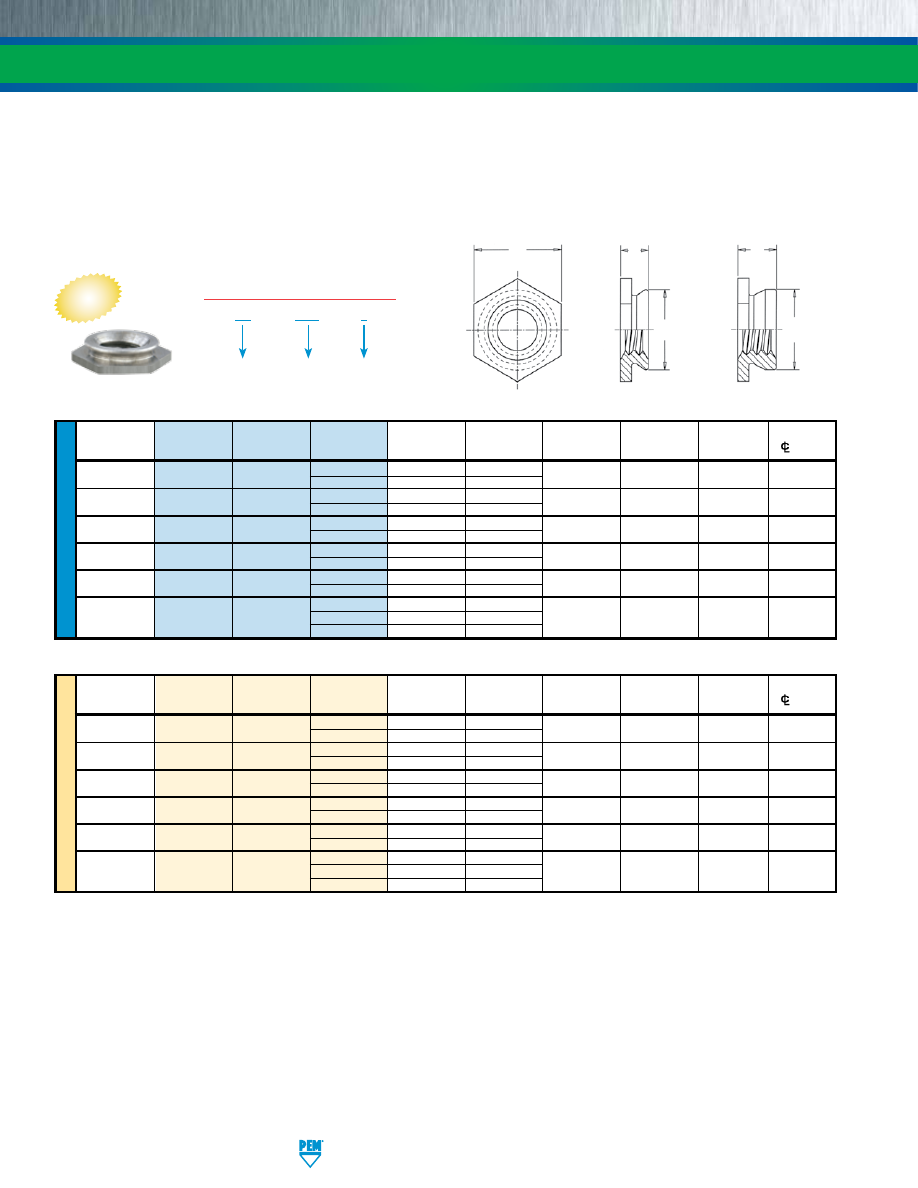
SS-6
PennEngineering • www.pemnet.com
FASTENERS FOR USE IN STAINLESS STEEL SHEETS
Profile for
-1 shank code.
Clinching profile may vary.
Profile for -2, -3, -4,
& -5 shank codes.
H
C
A
C
A
ME
TR
IC
U
NIF
IE
D
Thread
Thread
Shank
A Sheet
Hole Size
C
H
Min. Dist. Hole
Size
Type
Code
Code
(Shank) Thickness
In Sheet
Max. Nom.
C/L
To Edge
Max.
+.003 -.000
.086-56
F4 256
1
.060 .060-.090 .172 .171 .188 .23
(#2-56)
2
.090
.091 Min.
.112-40
F4 440
1
.060 .060-.090 .172 .171 .188 .23
(#4-40)
2
.090
.091 Min.
.138-32
F4 632
1
.060 .060-.090 .213 .212 .250 .27
(#6-32)
2
.090
.091 Min.
.164-32
F4 832
1
.060 .060-.090 .290 .289 .312 .28
(#8-32)
2
.090
.091 Min.
.190-32
F4 032
1
.060 .060-.090 .312 .311 .343 .31
(#10-32)
2
.090
.091 Min.
.250-20
3
.120 .125-.155
(1/4-20) F4 0420 4
.151 .156-.186 .344 .343 .375 .34
5
.182
.187 Min.
Thread
Thread Shank A Sheet
Hole Size
C
H
Min. Dist. Hole
Size x
Type
Code Code (Shank) Thickness
In Sheet
Max. Nom.
C/L
To Edge
Pitch
Max.
+0.08
M2 x 0.4
F4
M2 1
1.53 1.53-2.3
4.37 4.35 4.8 6
2
2.3
2.32 Min.
M2.5 x 0.45
F4
M2.5 1
1.53 1.53-2.3 4.37 4.35 4.8 6
2
2.3
2.32 Min.
M3 x 0.5
F4
M3 1
1.53 1.53-2.3 4.37 4.35 4.8 6
2
2.3
2.32 Min.
M4 x 0.7
F4
M4 1
1.53 1.53-2.3 7.37 7.35 7.9 7.2
2
2.3
2.32 Min.
M5 x 0.8
F4
M5 1
1.53 1.53-2.3 7.92 7.9 8.7 8
2
2.3
2.32 Min.
3
3.05
3.18-3.94
M6 x 1
F4
M6
4
3.84
3.96-4.72
8.74
8.72
9.5
8.8
5
4.63
4.75 Min.
All dimensions are in inches.
All dimensions are in millimeters.
F4 – 440 – 1
PART NUMBER DESIGNATION
Type and
Material
Thread
Code
Shank Code
TYPE F4™ PEMSERT® SELF-CLINCHING FLUSH FASTENERS
•
Can be installed into sheets as thin as .060”/1.53mm.
•
Ideal for flush applications where a stainless steel sheet requires load-bearing threads.
•
C
an be installed before bending and forming to provide strong threads while still remaining
flat with no protrusions on either surface.
•
For use in stainless steel sheets HRB 88 / HB 183 or less.
The increased hardness of stainless steel panels requires careful consideration when installing self-clinching fasteners.
Refer to Dos and Don’ts on page 24 for further information.
NEW
pem-html.html
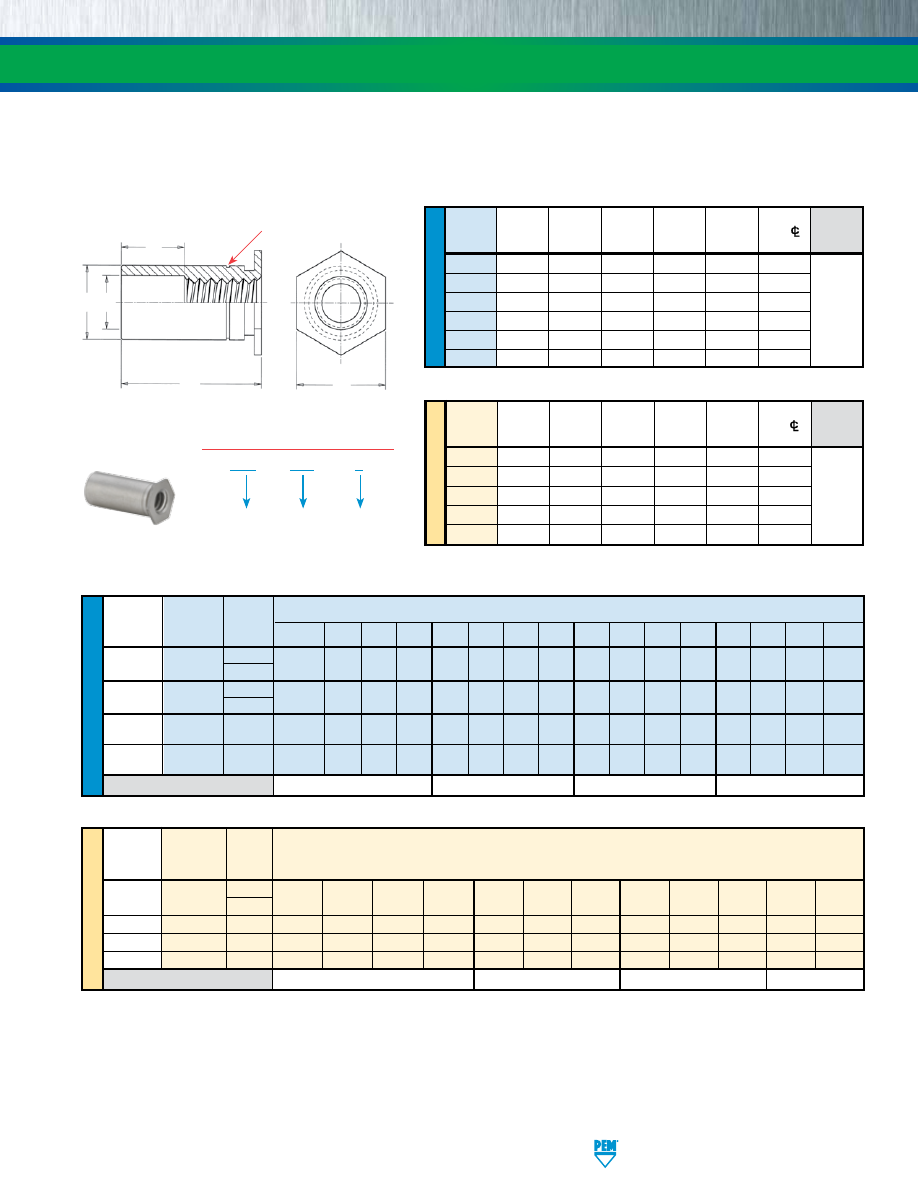
PennEngineering • www.pemnet.com
SS-7
FASTENERS FOR USE IN STAINLESS STEEL SHEETS
THREAD SIZE AND LENGTH SELECTION DATA
All dimensions are in inches.
GENERAL DIMENSIONAL DATA
All dimensions are in inches.
All dimensions are in millimeters.
All dimensions are in millimeters.
(1) To minimize sheet distortion and maximize product performance, use a centerline-to-edge value greater or equal to the value specified.
(2) Standoffs with thread codes 6440, 8632, and 3.5M3 offer greater wall thickness for thread sizes 440, 632, and M3 respectively.
•
Ideal for stacking or spacing.
•
Installed with head flush with one surface of the mounting sheet.
•
For use in stainless steel sheets HRB 88 / HB 183 or less.
H
L
D
B
C
Clinching profile may vary.
Location of PEM single “groove”
trademark may vary.
SO4 – 440 – 8
PART NUMBER DESIGNATION
Type and
Material
Thread
Code
Length
Code
TYPE SO4™ THRU-HOLE THREADED STANDOFFS
ME
TR
IC
U
NIF
IE
D
Min.
Hole Size
B
Thread Sheet
In Sheet
Counter-
C H
Min. Dist.
D
Code
Thickness
+.003
Bore Dia.
+.000 Nom. Hole
C/
±.010
-.000 ±.005 -.005
To Edge
(1)
440 .040 .166 .125 .165 .187 .23
6440 .040 .213 .125 .212 .250 .27
632 .040 .213 .156 .212 .250 .27
8632 .050 .281 .156 .280 .312 .31
832 .050 .281 .188 .280 .312 .31
032 .050 .281 .203 .280 .312 .31
Min. B
Thread Sheet
Hole Size Counter- C
H Min. Dist.
D
Code
Thickness
In Sheet Bore Dia.
-0.13
Nom.
Hole
C/
±0.25
+0.08 ±0.13
To Edge
(1)
M3 1 4.22 3.25 4.2 4.8 6
3.5M3 1 5.41 3.25 5.39 6.4 6.8
M3.5 1 5.41 3.9 5.39 6.4 6.8
M4 1.27 7.14 4.8 7.12 7.9 8
M5 1.27 7.14 5.35 7.12 7.9 8
Varies
according
to length.
See length
charts
below.
Varies
according
to length.
See length
charts
below.
ME
TR
IC
U
NIF
IE
D
Length “L” +.002 –.005 (Length Code in 32nds of an inch)
Thread Type Thread
Size
Code
.125 .187 .250 .312 .375 .437 .500 .562 .625 .687 .750 .812 .875 .937 1.00 1.062
.112-40
SO4
440
4 6 8 10 12 14 16 18 20 22 24 — — — — —
(#4-40) 6440
(2)
.138-32
SO4
632
4 6 8 10 12 14 16 18 20 22 24 26 28 30 32 34
(#6-32) 8632
(2)
.164-32
SO4 832 4 6 8 10 12 14 16 18 20 22 24 26 28 30 32 34
(#8-32)
.190-32
SO4
032
4 6 8 10 12 14 16 18 20 22 24 26 28 30 32 34
(#10-32)
D Dimension ±.010
None
.187
.312
.437
Thread Type Thread Length “L” +0.05 –0.13
Size x
Code
(Length Code in millimeters)
Pitch
M3 x 0.5
SO4
M3
3 4 6 8 10 12 14 16 18 — — —
3.5M3
(2)
M3.5 x 0.6
SO4
M3.5
3 4 6 8 10 12 14 16 18 20 22 25
M4 x 0.7
SO4
M4
3
4
6
8
10
12
14
16
18
20
22
25
M5
x 0.8
SO4
M5
3 4 6 8 10 12 14 16 18 20 22 25
D Dimension ±0.25
None
4
8
11
The increased hardness of stainless steel panels requires careful consideration when installing self-clinching fasteners.
Refer to Dos and Don’ts on page 24 for further information.
pem-html.html
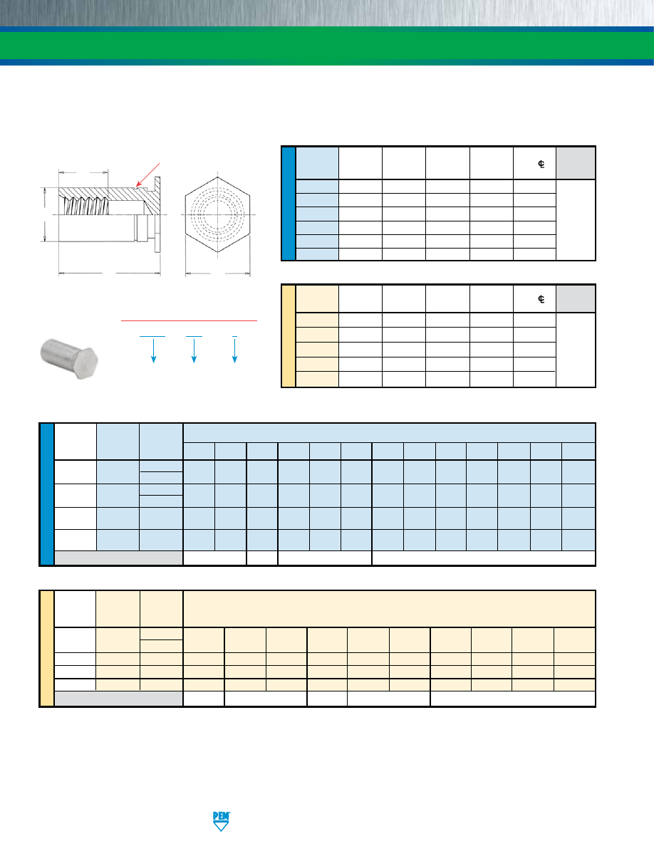
SS-8
PennEngineering • www.pemnet.com
FASTENERS FOR USE IN STAINLESS STEEL SHEETS
(1) To minimize sheet distortion and maximize product performance, use a centerline-to-edge value greater or equal to the value specified.
(2) Standoffs with thread codes 6440, 8632, and 3.5M3 offer greater wall thickness for thread sizes 440, 632, and M3 respectively.
•
Ideal for stacking or spacing.
•
Installed with closed end head flush with one surface of the mounting sheet.
•
For use in stainless steel sheets HRB 88 / HB 183 or less.
GENERAL DIMENSIONAL DATA
All dimensions are in inches.
All dimensions are in millimeters.
H
C
F
L
Clinching profile may vary.
Location of PEM single “groove”
trademark may vary.
THREAD SIZE AND LENGTH SELECTION DATA
All dimensions are in inches.
All dimensions are in millimeters.
BSO4 – 440 – 8
PART NUMBER DESIGNATION
Type and
Material
Thread
Code
Length
Code
TYPE BSO4™ BLIND THREADED STANDOFFS
ME
TR
IC
U
NIF
IE
D
Min.
Hole Size
Thread Sheet
In Sheet
C H
Min. Dist.
F
Code Thickness +.003
+.000 Nom. Hole
C/
Min.
-.000
-.005 To Edge
(1)
440 .040 .166 .165 .187 .23
6440 .040 .213 .212 .250 .27
632 .040 .213 .212 .250 .27
8632 .050 .281 .280 .312 .31
832 .050 .281 .280 .312 .31
032 .050 .281 .280 .312 .31
Min.
Hole Size
Min. Dist.
Thread
Sheet
In Sheet
C H
Hole
C/
F
Code Thickness +0.08 -0.13 Nom.
To Edge
(1)
Min.
M3 1 4.22 4.2 4.8 6
3.5M3 1 5.41 5.39 6.4 6.8
M3.5 1 5.41 5.39 6.4 6.8
M4 1.27 7.14 7.12 7.9 8
M5 1.27 7.14 7.12 7.9 8
Varies
according
to length.
See length
charts
below.
Varies
according
to length.
See length
charts
below.
ME
TR
IC
U
NIF
IE
D
Length “L” +.002 –.005 (Length Code in 32nds of an inch)
Thread Type Thread
Size
Code
.312 .375 .437 .500 .562 .625 .687 .750 .812 .875 .937 1.00 1.062
.112-40 440
10 12 14 16 18 20 22 24 26 28 30 32 34
(#4-40)
BSO4
6440
(2)
.138-32 632
10 12 14 16 18 20 22 24 26 28 30 32 34
(#6-32)
BSO4
8632
(2)
.164-32
BSO4 832 10 12 14 16 18 20 22 24 26 28 30 32 34
(#8-32)
.190-32
BSO4 032 10 12 14 16 18 20 22 24 26 28 30 32 34
(#10-32)
F Dimension Min.
.156
.187
.250
.375
Thread Type
Thread
Length “L” +0.05 –0.13
Size x
Code
(Length Code in millimeters)
Pitch
M3 x 0.5
BSO4
M3
6 8 10 12 14 16 18 20 22 25
3.5M3
(2)
M3.5 x 0.6
BSO4
M3.5
6 8 10 12 14 16 18 20 22 25
M4
x 0.7
BSO4
M4
6
8
10
12
14
16
18
20
22
25
M5
x 0.8
BSO4
M5
6 8 10 12 14 16 18 20 22 25
F Dimension Min.
3.2
4
5
6.5
9.5
The increased hardness of stainless steel panels requires careful consideration when installing self-clinching fasteners.
Refer to Dos and Don’ts on page 24 for further information.
pem-html.html
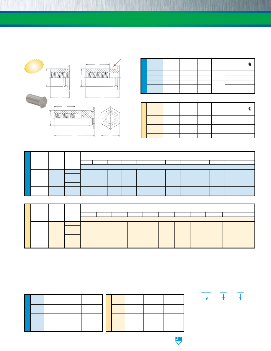
PennEngineering • www.pemnet.com
SS-9
FASTENERS FOR USE IN STAINLESS STEEL SHEETS
U
NIF
IE
D
ME
TR
IC
ME
TR
IC
U
NIF
IE
D
Min.
Hole Size
C
F Min.
Min. Dist.
Thread
Sheet
In Sheet
+.000
Thread
H
Hole
C/
Code
Thickness
+.003 -.000
-.005
Depth
Nom.
To Edge
256 .025 .166 .165
.200
.187 .23
6256 .025 .213 .212 .250 .27
440 .025 .166 .165
.220
.187 .23
6440 .025 .213 .212 .250 .27
632 .025 .213 .212 .270 .250 .27
(1) Style #1. Thru-threaded.
(2) Style #2. Screw might not pass through unthreaded end. Tapped to minimum full thread depth shown. Incomplete threads on tap may allow screw
to pass through.
(3) Style #3. Blind.
(4) Standoffs with thread codes 6256, 6440, 6M25 and 6M3 offer oversized body for increased bearing surface, wall thickness and performance.
Please contact your local PEM
®
distributor for availability, minimum quantity, and pricing information.
Min.
Hole Size
F Min.
Min. Dist.
Thread
Sheet
In Sheet
C
Thread
H
Hole
C/
Code
Thickness
+0.08
-0.13
Depth
Nom.
To Edge
M25 0.63 4.22 4.2
5.2
4.8 5.8
6M25 0.63 5.41 5.39 6.4 7.1
M3 0.63 4.22 4.2
6.2
4.8 5.8
6M3 0.63 5.41 5.39 6.4 7.1
M35 0.63 5.41 5.39 7 6.4 7.1
U
NIF
IE
D
Thread
Type
Thread
.090 .125 .187 .250 .312 .375 .437 .500 .562 .625 .687 .750
Size Code
Length Code (Length “L” without decimal point)
.086-56
TSO4
256
090
(1)
125
(1)
187
(1)
250
(1)
312
(2)
375
(2)
437
(3)
500
(3)
562
(3)
625
(3)
687
(3)
750
(3)
(#2-56)
6256
(4)
.112-40
TSO4 440 090
(1)
125
(1)
187
(1)
250
(1)
312
(2)
375
(2)
437
(2)
500
(3)
562
(3)
625
(3)
687
(3)
750
(3)
(#4-40) 6440
(4)
.138-32
TSO4 632 – 125
(1)
187
(1)
250
(1)
312
(1)
375
(2)
437
(2)
500
(2)
562
(3)
625
(3)
687
(3)
750
(3)
(#6-32)
Thread
Length “L”
Length “L”
Length “L”
Code
(Style #1)
(Style #2)
(Style #3)
256
.090 - .250
.251 - .375
.376 - .750
6256
440
.090 - .280
.281 - .450
.451 - .750
6440
632
.120 - .350
.351 - .540
.541 - .750
ME
TR
IC
Thread
Size x
Type
Thread
Pitch Code
2.00 3.00 4.00 6.00 8.00 10.00 12.00 14.00 16.00 18.00 19.00
Length Code (Length “L” without decimal point)
M2.5 x 0.45 TSO4
M25 200
(1)
300
(1)
400
(1)
600
(1)
800
(2)
1000
(3)
1200
(3)
1400
(3)
1600
(3)
1800
(3)
1900
(3)
6M25
(4)
M3 x 0.5 TSO4 M3 200
(1)
300
(1)
400
(1)
600
(1)
800
(2)
1000
(2)
1200
(3)
1400
(3)
1600
(3)
1800
(3)
1900
(3)
6M3
(4)
M3.5 x 0.6
TSO4
M35
– 300
(1)
400
(1)
600
(1)
800
(1)
1000
(2)
1200
(2)
1400
(3)
1600
(3)
1800
(3)
1900
(3)
Style #1
C
L
Style #2
C
F
L
C
F
H
L
Style #3
Thread
Length “L”
Length “L”
Length “L”
Code
(Style #1)
(Style #2)
(Style #3)
M25
2.00 - 6.30
6.32 - 9.50
9.52 - 19.00
6M25
M3
2.00 - 7.50
7.52 - 11.00
11.02 - 19.00
6M3
M35
3.00 - 8.80
8.82 - 12.80
12.82 - 19.00
All dimensions are in millimeters.
GENERAL DIMENSIONAL DATA
All dimensions are in inches.
THREAD SIZE AND LENGTH SELECTION DATA
All dimensions are in inches.
All dimensions are in millimeters.
LENGTH/STYLE DATA
All dimensions are in inches.
(Length can be specified in .001” increments.)
All dimensions are in millimeters.
(Length can be specified in .02 mm increments.)
Length “L”
±
.003
For other lengths / thread depth data see chart at bottom of page.
Length “L”
±
0.08
For other lengths / thread depth data see chart at bottom of page.
NEW
TYPE TSO4™ STANDOFFS FOR INSTALLATION INTO ULTRA-THIN STAINLESS STEEL SHEETS
Clinching profile may vary.
Location of
PEM single
“groove”
trademark
may vary.
•
For installation into ultra-thin stainless steel sheets as thin as .025”/0.63mm.
•
Threads on barrel end eliminate the need for long screws.
•
For use in stainless steel sheets HRB 88 / HB 183 or less.
The increased hardness of stainless steel
panels requires careful consideration
when installing self-clinching fasteners.
Refer to Dos and Don’ts on page 24 for
further information.
TSO4 – 440 – 250
PART NUMBER DESIGNATION
Type and
Material
Thread
Code
Length
Code
pem-html.html
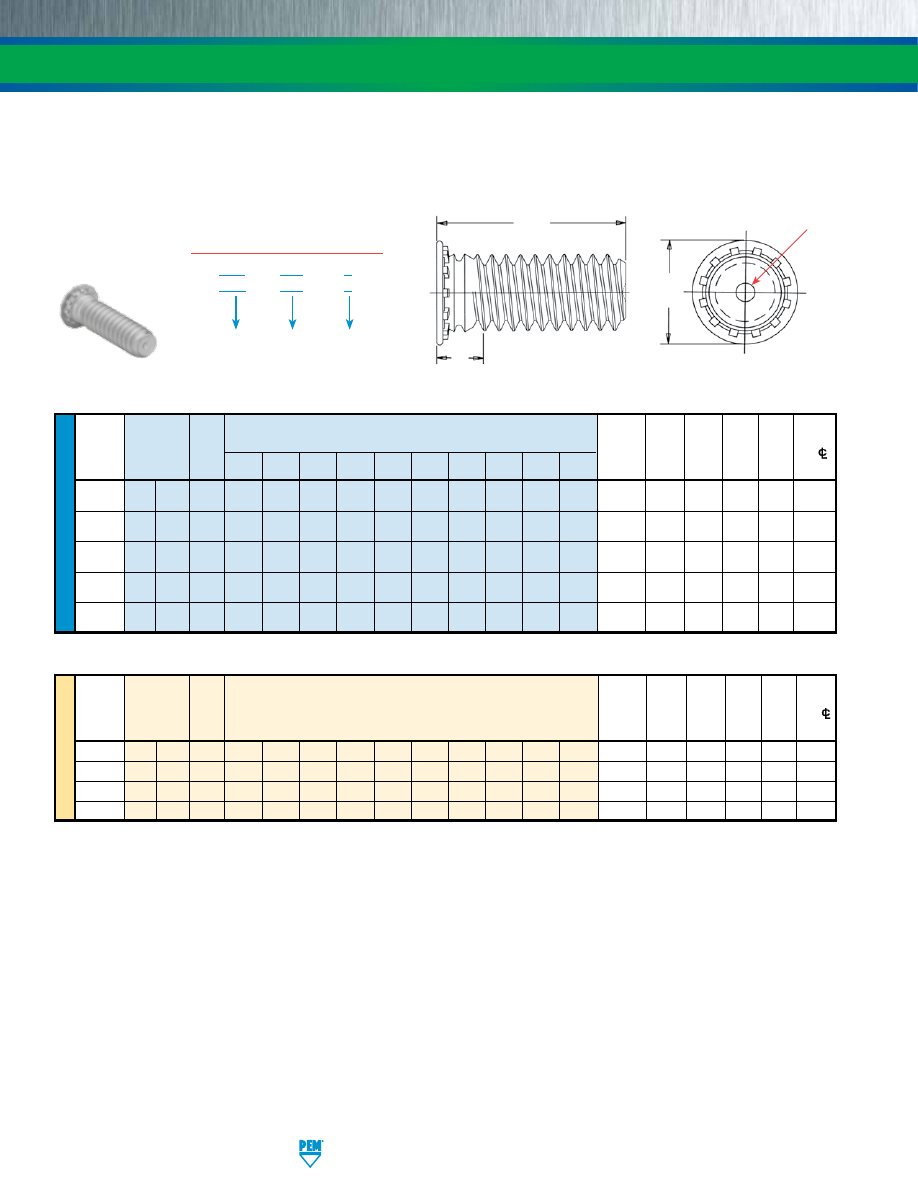
SS-10
PennEngineering • www.pemnet.com
FASTENERS FOR USE IN STAINLESS STEEL SHEETS
ME
TR
IC
U
NIF
IE
D
•
Permanent installation into stainless steel sheets as thin as .040”/1mm.
•
Type FHP offers highest corrosion resistance and ideal for medical, food service, and marine applications.
•
For use in stainless steel sheets HRB 92 / HB 202 or less.
(1) Performance may be reduced for studs installed into thicker sheets.
(2) Threads are gaugeable to within 2 pitches of the “S” Max. dimension. A class 3B/5H maximum material commercial nut shall pass up to the “S” Max.
dimension.
Length Code “L” ±.015
Hole
Max.
Min.
Thread Thread
(Length code in 16ths of an inch)
Size
in
Hole
H S
Dist.
Size Type
Code
Sheet Sheet in ±.015 Max. Hole
C/L
.250 .312 .375 .500 .625 .750 .875 1.00 1.25 1.50
Thickness +.003 Attach.
(2)
to Edge
(1) -.000 Parts
.112-40 FH4
FHP
440 4 5 6 8 10 12 14 16 — —
.040-.095
.111 .131 .176
.085
.219
(#4-40)
.138-32 FH4 FHP 632 4 5 6 8 10 12 14 16 20 24 .040-.095 .137 .157 .206 .090 .250
(#6-32)
.164-32 FH4 FHP 832 4 5 6 8 10 12 14 16 20 24 .040-.095 .163 .183 .237 .090 .281
(#8-32)
.190-32 FH4 FHP 032 — 5 6 8 10 12 14 16 20 24 .040-.095 .189 .209 .256 .100 .281
(#10-32)
.250-20 FH4 — 0420 — — 6 8 10 12 14 16 20 24 .062-.117 .249 .269 .337 .135 .312
(1/4-20)
Length Code “L” ±0.4
Hole Max. Min.
Thread
Thread
(Length Code in millimeters)
Size in Hole H S
Dist.
Size x Type
Code
Sheet
Sheet in ±0.4 Max. Hole
C/L
Pitch
Thickness
+0.08 Attach.
(2)
to Edge
(1) parts
M3 x 0.5
FH4 FHP
M3
6
8
10
12
15
18
20
25
—
—
1 - 2.4
3
3.3
4.6
2.1
5.6
M4 x 0.7
FH4 FHP
M4
6
8
10
12
15
18
20
25
30
35
1 - 2.4
4
4.7
5.9
2.4
7.2
M5 x 0.8
FH4 FHP
M5
—
8
10
12
15
18
20
25
30
35
1 - 2.4
5
5.3
6.5
2.7
7.2
M6
x 1
FH4
—
M6
—
—
10
12
15
18
20
25
30
35
1.6 - 3
6
6.8
8.2
3
7.9
All dimensions are in inches.
All dimensions are in millimeters.
FH4 – 632 – 6
FHP – 632 – 6
PART NUMBER DESIGNATION
Type and
Material
Thread
Code
Length
Code
TYPE FH4™/FHP™ FLUSH-HEAD STUDS
The increased hardness of stainless steel panels requires careful consideration when installing self-clinching fasteners.
Refer to Dos and Don’ts on page 24 for further information.
S
L
H
unthreaded length
Look for the PEM
“Dimple” trademark.
Clinching profile may vary.
pem-html.html
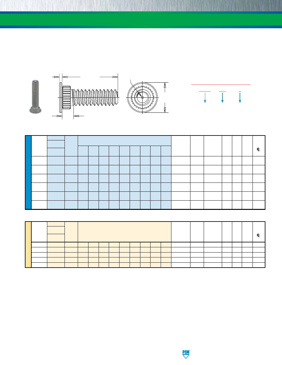
PennEngineering • www.pemnet.com
SS-11
FASTENERS FOR USE IN STAINLESS STEEL SHEETS
All dimensions are in inches.
All dimensions are in millimeters.
U
NIF
IE
D
Type
Length Code “L” ±.015
Hole
Hole
Min.
Fastener
(Length Code in 16ths of an inch)
Size in
Dia. of
Dist.
Thread
Material
Thread Sheet Sheet
Attached H
S T Hole
Size
Stainless
Code
.312 .375 .500 .625 .750 .875 1.00 1.25 1.50 Thickness +.003 Panel
±.010 Max. ±.004
Steel (2) -.000
+.005
–.000 (3)
to Edge
.086-56
SGPC
256
5
6
8
10
12
—
—
—
—
.024 - .047
.145
.182
.189 .093
.020
.130
(#2-56)
.112-40
SGPC
440
5
6
8
10
12
14
16
20
—
.024 - .047
.171
.205
.228
.101
.024
.160
(#4-40)
.138-32
SGPC
632
5
6
8
10
12
14
16
20
24
.024 - .047
.196
.229
.256 .109
.024
.180
(#6-32)
.164-32
SGPC
832
5
6
8
10
12
14
16
20
24
.024 - .047
.223
.259
.279 .109
.024
.200
(#8-32)
.190-32
SGPC
032
5
6
8
10
12
14
16
20
24
.024 - .047
.249
.280
.307 .109
.024
.210
(#10-32)
.250-20
SGPC
0420
—
6
8
10
12
14
16
20
24
.024 - .047
.309
.343
.366
.131
.028
.250
(1/4-20)
ME
TR
IC
Type
Hole
Min.
Fastener
Hole Dia.
of Dist.
Thread
Material
Thread
Length Code “L” ±0.4
Sheet
Size in
Attached
H
S T Hole
Size x
Stainless
Code
(Length Code in millimeters) Thickness Sheet Panel
±0.25 Max. ±0.1
Pitch
Steel (2) +0.08 +0.13
(3)
to Edge
M2.5 x 0.45
SGPC
M2.5
8
10
12
15
18
—
—
—
—
0.6 - 1.2
4
4.95
5
2.4
0.5
3.9
M3 x 0.5
SGPC
M3
8
10
12
15
18
20
25
—
—
0.6 - 1.2
4.5
5.45
6
2.5
0.6
4.3
M4 x 0.7
SGPC
M4
8
10
12
15
18
20
25
30
—
0.6 - 1.2
5.5
6.3
7
2.7
0.6
4.9
M5 x 0.8
SGPC
M5
8
10
12
15
18
20
25
30
35
0.6 - 1.2
6.5
7.45
8
2.8
0.6
5.5
M6 x 1
SGPC
M6
—
10
12
15
18
20
25
30
35
0.6 - 1.2
7.5
8.3
9
3
0.7
6.2
(1) When using the fastener to attach more than one sheet or panel, the stud may seem slightly loose after installation. This is a normal condition in some
applications and will not affect the stud’s performance.
(2) See installation data for tooling requirements. Contact Technical Support (techsupport@pemnet.com) for other thicknesses.
(3) Threads are gaugeable to within 2 pitches on the “S” Max. dimension. A class 3B/5H maximum material commercial nut shall pass up to the “S” Max.
dimension.
H
L
T
S
Look for the PEM
“Dimple” trademark.
unthreaded length
•
Installs into sheets as thin as .024”/0.6mm.
•
Can be used to attach dissimilar materials.
•
Can accommodate multiple panels as long as the total thickness does not exceed the maximum sheet thickness.
(1)
•
Can be installed into most panel materials, including stainless steel.
•
Allows for close centerline-to-edge distance.
TYPE SGPC™ SWAGING COLLAR STUDS
SGPC – 632 – 8
PART NUMBER DESIGNATION
Type and
Material
Thread
Code
Length
Code
pem-html.html
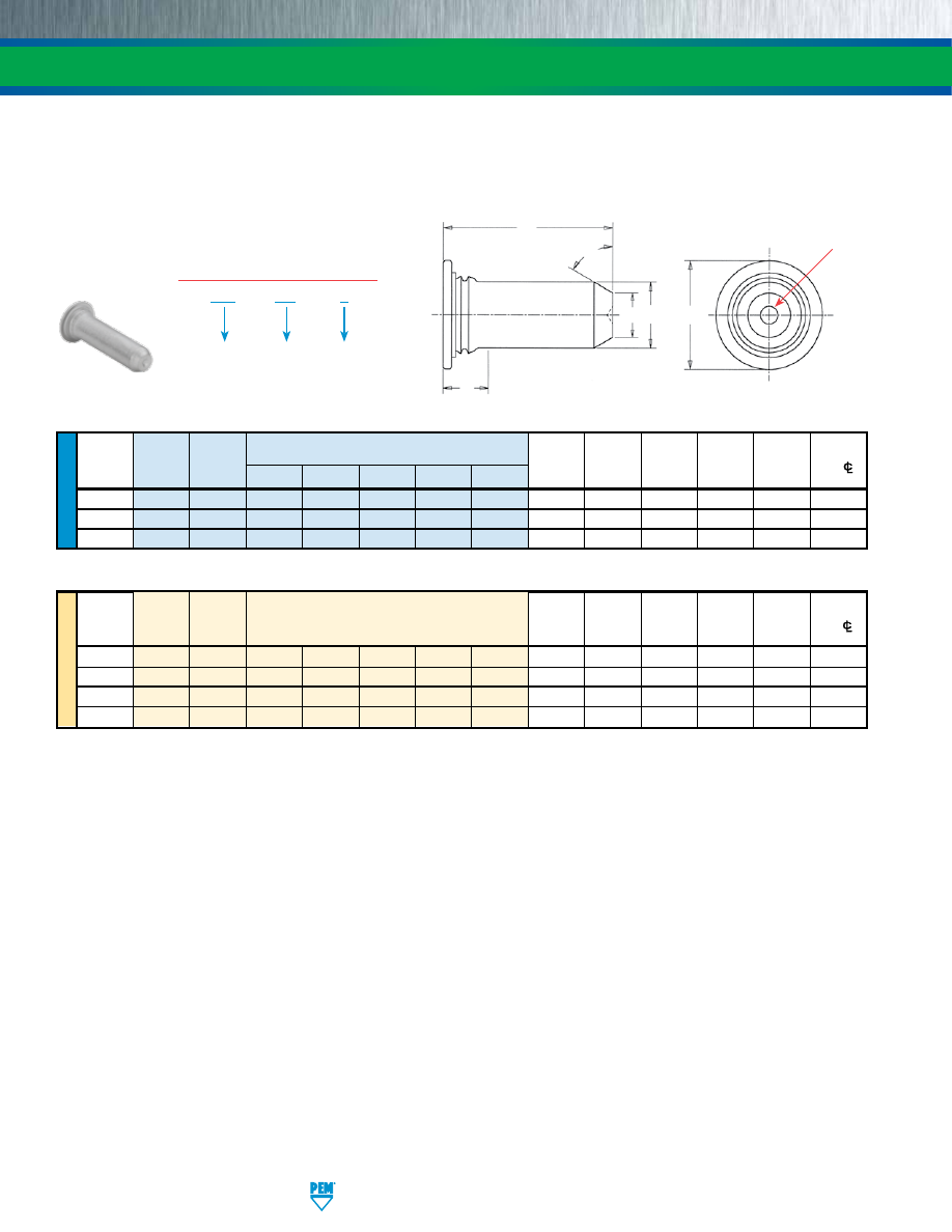
SS-12
PennEngineering • www.pemnet.com
FASTENERS FOR USE IN STAINLESS STEEL SHEETS
ME
TR
IC
U
NIF
IE
D
Length Code “L” ± .015
Min.
Pin Pin
(Length Code in 16ths of an inch)
Min.
Hole Size D H S Distance
Diameter
Type
Diameter
Sheet
in Sheet ±.006 ±.015 Max. Hole
C/L
P ±.002 Code
.375 .500 .625 .750 1.00
Thickness
+.003 -.000
(1)
to Edge
.125 TP4 125 6 8 10 12 — .040 .144 .090 .205 .090 .250
.187
TP4
187
6
8
10
12
16
.040
.205
.132
.270
.090
.280
.250
TP4
250
—
8
10
12
16
.040
.272
.177
.335
.090
.310
Length Code “L” ± 0.4
Min.
Pin Pin
(Length Code in millimeters)
Min.
Hole Size D H S Distance
Diameter
Type
Diameter
Sheet
in Sheet ±0.15 ±0.4 Max. Hole
C/L
P ±0.05 Code
Thickness +0.08 (1)
to Edge
3 TP4 3MM 8 10 12 16 — 1 3.5 2.05 5.2 2.29 6.4
4
TP4
4MM 8 10 12 16 — 1 4.5 2.82 6.12 2.29 7.1
5
TP4
5MM
— 10 12 16 20 1 5.5 3.53 7.19 2.29 7.6
6
TP4
6MM
— — 12 16 20 1 6.5 4.24 8.13 2.29 7.9
(1) Pin diameter may exceed max. in this region.
All dimensions are in inches.
All dimensions are in millimeters.
•
Permanent installation into stainless steel sheets as thin as .040”/1mm.
•
Satisfies a wide range of positioning, pivot, and alignment applications.
•
Chamfered end makes mating hole location easy.
•
For use in stainless steel sheets HRB 92 / HB 202 or less.
TP4 – 125 – 8
PART NUMBER DESIGNATION
Type and
Material
Pin Diameter
Code
Length
Code
TYPE TP4™ FLUSH-HEAD PINS
The increased hardness of stainless steel panels requires careful consideration when installing self-clinching fasteners.
Refer to Dos and Don’ts on page 24 for further information.
H
L
64° ±5°
S
P
D
Look for the PEM
“Dimple” trademark.
Clinching profile may vary.
pem-html.html
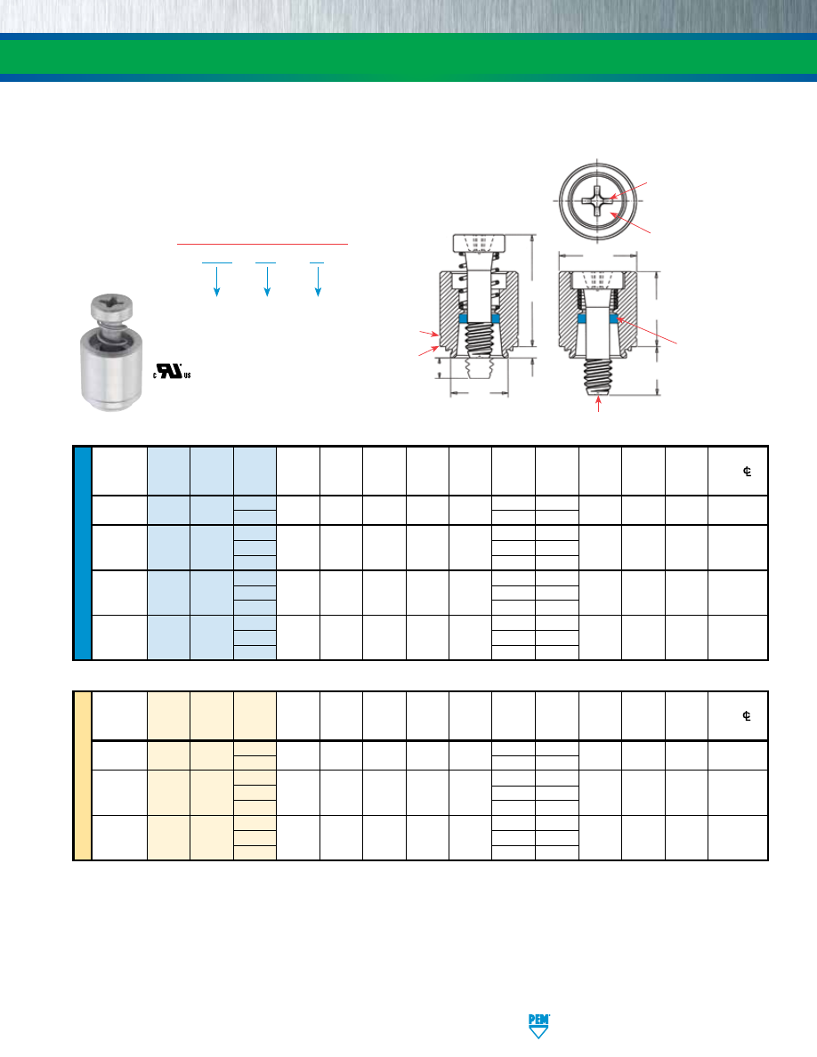
PennEngineering • www.pemnet.com
SS-13
FASTENERS FOR USE IN STAINLESS STEEL SHEETS
ME
TR
IC
U
NIF
IE
D
Screw A
Min.
Hole
Size
Min. Dist.
Thread
Thread Length (Shank)
Sheet
In Sheet
C
E
G
P
T
1
T
2
Driver
Hole
C/L
Size
Type Code
Code Max.
Thickness
+ .003
Max.
± .010
± .016
±.025
Max.
Nom.
Size
To Edge
(1)
-
.000
.112-40
PFC4 440
40
.060 .060 .265 .264 .344
.250 .000
.370 .540 #1 .25
(#4-40) 62 .375
.125
40 .250
.000
.138-32 PFC4 632 62 .060 .060 .281 .280 .375 .375 .125 .380 .540 #2 .28
(#6-32)
84 .500
.250
50 .312
.000
.164-32 PFC4 832 72 .060 .060 .312 .311 .406 .437 .125 .480 .705 #2 .31
(#8-32)
94 .562
.250
50 .312
.000
.190-32 PFC4 032 72 .060 .060 .344 .343 .437 .437 .125 .490 .705 #2 .34
(#10-32)
94 .562
.250
(1) To minimize sheet distortion and maximize product performance, use a centerline-to-edge value greater or equal to the value specified.
Screw A
Min.
Hole Size
Min. Dist
Thread Thread
Length (Shank)
Sheet
In Sheet C E G P T
1
T
2
Driver
Hole
C/L
Size x
Type Code
Code Max.
Thickness
+ 0.08
Max.
± 0.25
± 0.4
±0.64
Max.
Nom.
Size
To Edge
(1)
Pitch
M3 x 0.5
PFC4
M3
40
1.53 1.53 6.73 6.71 8.74
6.4 0
9.4 13.72 #1 6.35
62 9.5
3.2
50 7.9 0
M4 x 0.7
PFC4
M4
72
1.53
1.53
7.92
7.9
10.31
11.1
3.2
12.19
17.91
#2
7.87
94
14.3
6.4
50 7.9 0
M5 x 0.8
PFC4
M5
72
1.53
1.53
8.74
8.72
11.1
11.1
3.2
12.45
17.91
#2
8.63
94
14.3
6.4
All dimensions are in inches.
All dimensions are in millimeters.
PFC4 – 832 – 50
PART NUMBER DESIGNATION
Type and
Material
Thread
Code
Screw
Length
Code
TYPE PFC4™ PANEL FASTENERS
•
Tool only access meets UL 1950 “service area access” requirements and
provides fixed screw solutions for the EC Machinery Directive.
•
Assorted screw lengths for most applications.
•
For use in stainless steel sheets HRB 88 / HB 183 or less.
The increased hardness of stainless steel panels requires careful consideration when installing self-clinching fasteners.
Refer to Dos and Don’ts on page 24 for further information.
Dimples on head
designates metric
thread.
T
2
T
1
E
C
A
G
Phillips
driver size.
(See chart)
PEM
Trademark
Blue plastic
retaining ring.
P
Shoulder
provides
positive
stop during
installation.
PEM “Dimple” trademark on end of screw.
Single “groove”
identifier.
Clinching profile may vary.
pem-html.html
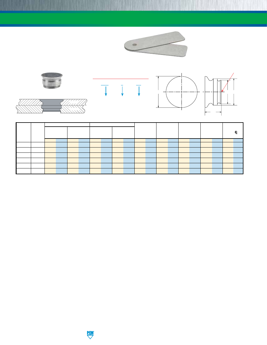
SS-14
PennEngineering • www.pemnet.com
FASTENERS FOR USE IN STAINLESS STEEL SHEETS
(1) Fastener will provide flush application at minimum sheet thickness.
Patented
SpotFast® fastener used as
a single flush-mounted pivot
point. Top panel rotates about
the SpotFast fastener.
•
Allows permanent joining of two metal sections.
•
Offers high corrosion resistance.
•
Can be used as single flush-mounted pivot point.
•
Installs smooth with top sheet and flush or sub-flush
with the bottom sheet.
•
For use in sheets of HRB 88 / HB 183 or less.
SFP – 3 – 1.0
PART NUMBER DESIGNATION
Type and
Material
Panel 1
Mounting
Hole Code
Thickness
Code
TYPE SFP™ SPOTFAST® FASTENERS
SpotFast
Fastener
Panel 1
Panel 2
The increased hardness of stainless steel panels requires careful consideration when installing self-clinching fasteners.
Refer to Dos and Don’ts on page 24 for further information.
Panel 1
Panel 2
Type
Thickness
Mounting Hole
Thickness
Mounting Hole
Min. Dist.
and
Thickness
±0.08 mm /
+0.08 mm /
Min.
+0.08 mm /
C
1
C
2
E
L
Hole
C/L
Size
Code
±.003”
+.003” –.000”
(1)
+.003” –.000”
Max.
Max.
Max.
Max.
To Edge
mm in. mm in. mm in. mm in. mm in. mm in. mm in. mm in. mm in.
SFP-3 1.0 1 .039 3 .118 1 .039 2.5 .098 2.98 .117 2.48 .097
3.76 .148 1.9 .075
2.54 .1
SFP-3 1.2 1.2 .047 3 .118 1.2 .047 2.5 .098 2.98 .117 2.48 .097 3.76 .148 2.31 .091 2.54 .1
SFP-3 1.6 1.6 .063 3 .118 1.6 .063 2.5 .098 2.98 .117 2.48 .097 3.76 .148 3.12 .123 2.54 .1
SFP-5 1.0 1 .039 5 .197 1 .039 4.5 .177 4.98 .196 4.47 .176 5.56
.219 1.9 .075 3.6 .14
SFP-5 1.2 1.2 .047 5 .197 1.2 .047 4.5 .177 4.98 .196 4.47 .176 5.56 .219 2.31 .091 3.6 .14
SFP-5 1.6 1.6 .063 5 .197 1.6 .063 4.5 .177 4.98 .196 4.47 .176 5.56 .219 3.12 .123 3.6 .14
C
2
C
1
L
E
Look for the PEM
“Dimple” trademark.
Clinching profile may vary.
pem-html.html
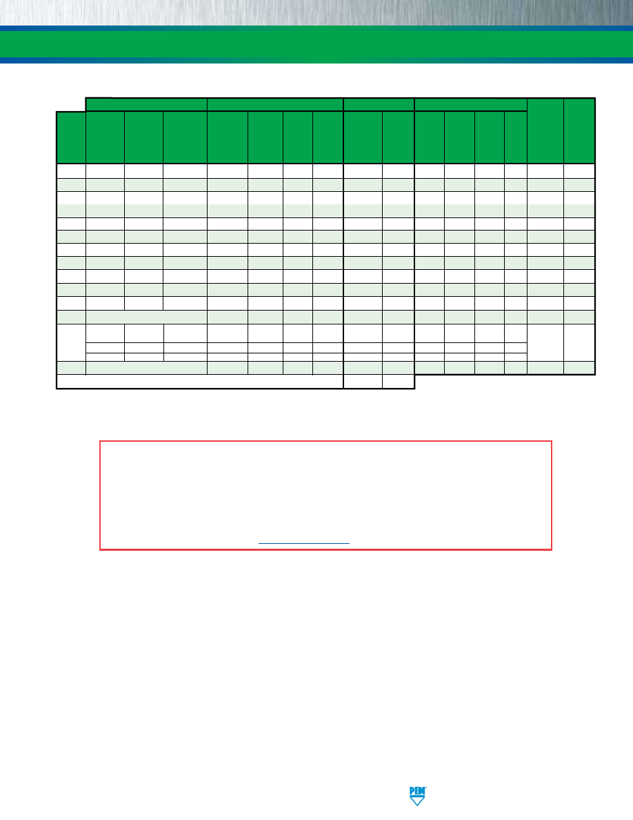
PennEngineering • www.pemnet.com
SS-15
FASTENERS FOR USE IN STAINLESS STEEL SHEETS
(1) HRB - Hardness Rockwell “B” Scale. HB - Hardness Brinell.
Threads
Fastener Materials
Finish
For Use in Sheet Hardness
(1)
Internal, External, Self-locking, Precipitation Heat-
300
Age Passivated
ASME
ASME
Internal ASME
Hardening
Treated
Series Hardened
and/or
Black
HRB 92 / HRB 90 / HRB 88 / Any
Corrosion
Type
B1.1 2B/
B1.1 2A/
B1.1, 3B/
Grade
400 Series Stainless
A286
Tested per
Dry-film
HB 202
HB 192
HB 183 Sheet Resistance Magnetic
ASME
ASME
ASME
Stainless
Stainless
Steel
Stainless ASTM A380 Lubricant or less
or less
or less Hard-
B1.13M, 6H
B1.13M, 6g
B1.13M, 6H
Steel
Steel
Steel
ness
SP
•
• • •
Excellent No
SMPP
•
• • •
Excellent No
A4
•
•
(retainer)
•
(insert)
•
•
Fair Yes
LA4
•
•
(retainer)
•
(insert)
•
(retainer)
•
(insert)
•
Fair Yes
F4
• • •
•
Fair Yes
SO4
• • •
•
Fair Yes
BSO4
• • •
•
Fair Yes
TSO4
• • •
•
Fair Yes
FH4
• • • •
Fair Yes
FHP
•
• • •
Excellent No
SGPC
• •
•
•
Excellent No
TP4
Not threaded
• • •
Fair Yes
PFC4
(Retainer)
• •
•
(Screw)
•
• •
Fair Yes
(Spring)
•
SFP
Not threaded
• •
•
Excellent Yes
Part number codes for finishes
None
MD
MATERIAL AND FINISH SPECIFICATIONS
A NOTE ABOUT FASTENERS FOR STAINLESS STEEL PANELS
In order for self-clinching fasteners to work properly, the fastener must be harder than the sheet into which it is being installed. In
the case of stainless steel panels, fasteners made from 300 Series Stainless Steel do not meet this hardness criteria. It is for this
reason that 400 series fasteners are offered (Types A4, LA4, F4, SO4, BSO4, TSO4, FH4, TP4, and PFC4). However, while these 400
Series fasteners install and perform well in 300 Series stainless sheets they should not be used if the end product:
•
Will be exposed to any appreciable corrosive presence.
•
Requires non-magnetic fasteners.
•
Will be exposed to any temperatures above 300˚F (149˚C)
If any of the these are issues, please contact
techsupport@pemnet.com
for other options.
pem-html.html
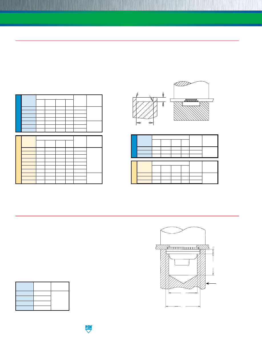
SS-16
PennEngineering • www.pemnet.com
FASTENERS FOR USE IN STAINLESS STEEL SHEETS
INSTALLATION
TYPES SP/SMPP
(1)
1.
Prepare properly sized mounting hole in sheet. Do not perform any secondary operations such as deburring.
2.
Place fastener into the recommended counterbore anvil hole and place the mounting hole over the shank of the fastener as shown
in diagram.
3.
With installation punch and anvil surfaces parallel, apply squeezing force until the head of the nut comes into contact with the sheet
material.
RECOMMENDED
COUNTERBORE ANVIL
R
R
1
P
A
(1) For best results, we recommend using the installation punch and anvil shown. Deviations from recommended installation tooling may result in sheet
distortion and reduced performance.
NOTE:
Variations in hole preparation, installation tooling, installation force, and sheet material type, thickness, and hardness will affect both performance
and tooling life.
PUNCH
ANVIL
U
NIF
IE
D
Anvil Dimensions (in.)
Anvil Punch
Thread
A
P +.000
R
R
1
Part Part
Code ±.002 –.001 Max. +.005 Number Number
440 .255 .064 .010 .005 8012821
632 .286 .064 .010 .005 8012822 975200048
832
.317 .082 .010 .005 8012823
024/032 .348 .082 .010 .005 8012824
0420 .443 .163 .010 .005 8012825
0518 .505 .230 .010 .005 8015359 8003076
0616/0624 .570 .263 .010 .005 8015863
ME
TR
IC
Anvil Dimensions (mm) Anvil Punch
Thread A
P
R
R
1
Part Part
Code ±0.05 –0.03 Max. +0.13 Number Number
M2 6.48 1.63 0.25 0.13 8012821
M2.5-0 6.48 1.42 0.25 0.13 8019477
M2.5-1,-2 6.48 1.63 0.25 0.13 8012821
M3 6.48 1.63 0.25 0.13 8012821 975200048
M3.5 7.26 1.63 0.25 0.13 8012822
M4 8.05 2.08 0.25 0.13 8012823
M5 8.84 2.08 0.25 0.13 8012824
M6 11.25 4.14 0.25 0.13 8012825
M8 12.83 5.41 0.25 0.13 8015360 8003076
M10 17.58 7.47 0.25 0.13 8015886
PEMSERTER® Installation Tooling
U
NIF
IE
D
Anvil Dimensions (in.)
Anvil Punch
Thread
A
P +.000
R
R
1
Part Part
Code ±.002 –.001 Max. +.005 Number Number
256
.223 .060 .010 .005 8020023
440 .233 .060 .010 .005 8021386 975200048
632
.255 .060 .010 .005 8020024
ME
TR
IC
Anvil Dimensions (mm) Anvil Punch
Thread
A P R R
1
Part Part
Code ±0.05 –0.03 Max. +0.13 Number Number
M2.5 5.66 1.27 0.25 0.13 8020025
M3
5.66 1.27 0.25 0.13 8021474 975200048
M3.5 6.48 1.27 0.25 0.13 8020026
SP
SMPP
TYPES A4/LA4
1.
Prepare properly sized mounting hole in sheet. Do not perform any
secondary operations such as deburring.
2.
Place fastener into the anvil hole and place the mounting hole
(preferably the punch side) over the shank of the fastener.
3.
With installation punch and anvil surfaces parallel, apply sufficient
squeezing force until the flange contacts the sheet material.
PUNCH
.25”/8mm Min.
D
+.002”/+0.05mm
+.005”/+0.13mm
ANVIL
E
+.004”/+0.1mm
–.000”
.054”/1.37mm
±.002”/±0.05mm
See page 5 for
“D” and “E”.
Thread
Anvil Part
Punch Part
Code
Number Number
440/M3
8013889
632
8013890 975200048
832/M4
8013891
032/M5
8013892
PEMSERTER® Installation Tooling
pem-html.html
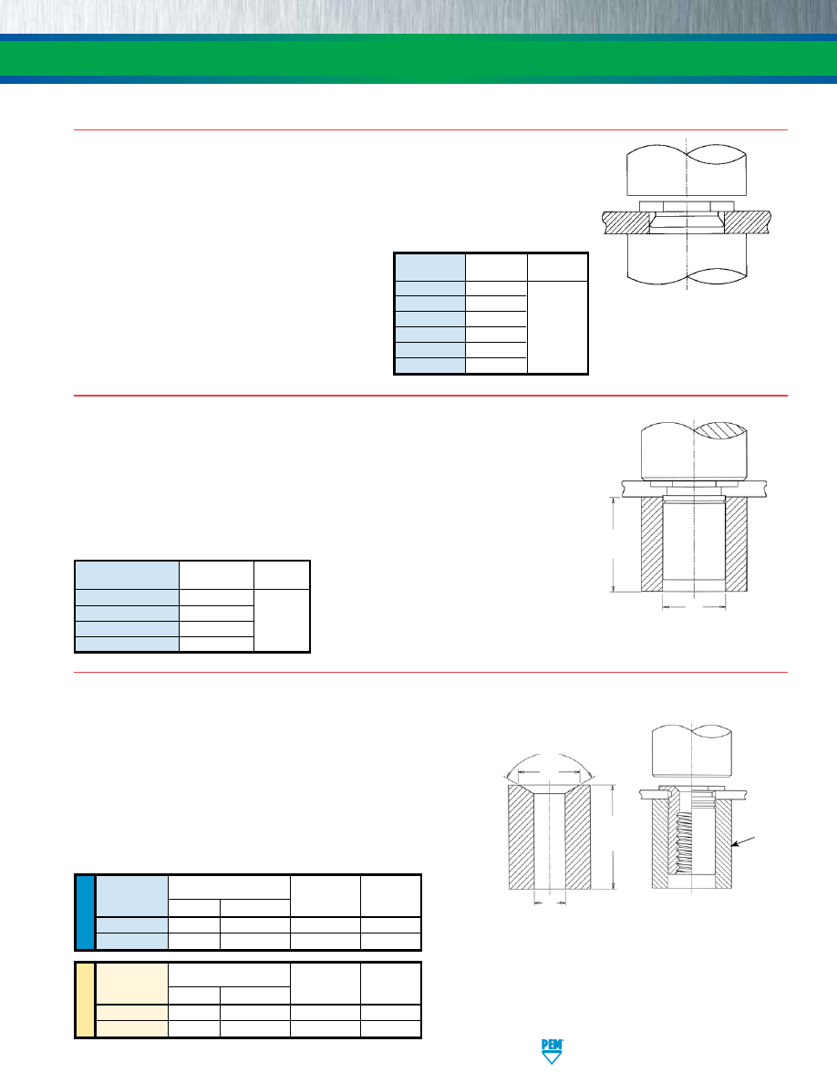
PennEngineering • www.pemnet.com
SS-17
FASTENERS FOR USE IN STAINLESS STEEL SHEETS
INSTALLATION
REQUIRED
INSTALL
AT
ION ANVIL
FOR SHEETS BELOW
.032”/0.81MM
L* Min.
B
120˚
PUNCH
ANVIL
TYPE TSO4
1.
Prepare properly sized mounting hole in sheet. Do not perform any
secondary operation such as deburring.
2.
Insert standoff through mounting hole (preferably the punch side) of
sheet and into anvil as shown in drawing.
3.
With installation punch and anvil surfaces parallel, apply only enough
squeezing force to embed the standoff’s head flush in the sheet.
Drawing at right shows required installation anvil for sheet thickness
of .025” to .032”/0.63 to 0.81mm. A chamfered anvil is not required for
sheets over .032”/0.81mm.
U
NIF
IE
D
Anvil Part No.
Thread
For Sheets
Punch Part
Code
B
Anvil Part No.
Over .032”
Number
256/440
.187 - .194
8003291
970200487300
975200048
6256/6440/632
.250 - .257
8003292
970200012300
975200048
PEMSERTER® Installation Tooling
C*
Anvil Dimensions (in.)
For Sheets Below .032”
ME
TR
IC
Anvil Part No.
Thread
For Sheets
Punch Part
Code
B
Anvil Part No.
Over 0.63 mm
Number
M2.5/M3
4.75 - 4.93
8003291
970200487300
975200048
6M25/6M3/M35
6.35 - 6.53
8003292
970200012300
975200048
Anvil Dimensions (mm)
For Sheets Below 0.63 mm
+.001” to +.004”/
+0.03mm to +0.1mm
*See page 9 for “C”
and “L”.
TYPES SO4/BSO4
1.
Prepare properly sized round mounting hole in sheet. Do not perform any secondary
operations such as deburring.
2.
Insert standoff barrel through (punched side of) mounting hole in sheet and into anvil as
shown.
3.
With installation punch and anvil surfaces parallel, apply only enough squeezing force to
embed the standoff’s head flush in the sheet.
C
“L” Min.
PUNCH
ANVIL
+.004”/0.1mm
+.007”/0.18mm
Thread
Anvil Part
Punch Part
Code
Number Number
440/M3 970200487300
632/6440/M3.5/3.5M3 970200012300 975200048
832/8632/M4 970200013300
032/M5 970200013300
PEMSERTER® Installation Tooling
See pages 7 and 8
for “C” and “L”.
TYPE F4
1.
Prepare properly sized round mounting hole in sheet.
Do not perform any secondary operations such as
deburring.
2.
Place shank of fastener into mounting hole (preferably
the punch side) as show in the drawing.
3.
With installation punch and anvil surfaces parallel,
apply sufficient squeezing force only to embed
hexagonal head flush in sheet. The metal displaced by
the head flows evenly and smoothly around the back-
tapered shank of the fastener, securely locking it into
place with high pullout resistance while at the same
time, the embedded hexagonal head provides high
torque resistance.
PUNCH
ANVIL
Thread
Anvil Part
Punch Part
Code
Number Number
256/M2/M2.5
8006193
440/M3
975200040
632
975200041 975200048
832/M4
975200042
1032/M5
975200043
0420/M6
975200044
PEMSERTER® Installation Tooling
pem-html.html
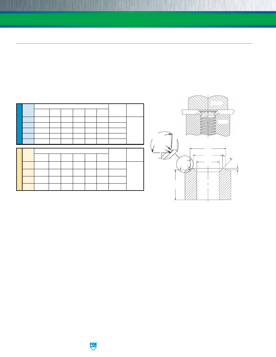
SS-18
PennEngineering • www.pemnet.com
FASTENERS FOR USE IN STAINLESS STEEL SHEETS
INSTALLATION
TYPES FH4/FHP
1.
Prepare properly sized mounting hole in sheet. Do not perform any secondary operations such as deburring.
2.
Insert stud through mounting hole (punch side) of sheet and into anvil hole.
3.
With punch and anvil surfaces parallel, apply squeezing force to embed the head of the stud flush in the sheet.
For Type FH4/FHP studs, a special anvil with a raised ring is required to create a proper installation. The raised ring acts as a second displacer of the
stainless sheet material, thereby ensuring that the annular groove is filled. Please see page 10 for recommended sheet thickness range.
The special anvils are available from PEM stock or can be machined from suitable tool steel. A hardness of HRC 55 / HB 547 minimum is required to provide
long anvil life. We recommend measuring the “P” dimension every 5000 installations to ensure that the anvil remains within specification.
ME
TR
IC
U
NIF
IE
D
Thread
Anvil Dimensions (in.)
Anvil Part
Punch Part
Code
A B C P R
1
R
2
Number Number
+.003 -.000 ±.002 ±.002
±.001
Max.
Max.
440 .113 .144 .174 .010 .003 .005 8001645
632
.140
.170 .200 .010 .003 .005 8001644
832
.166
.202 .236 .010 .003 .005 8001643 975200048
032
.191
.235 .275 .010 .003 .005 8001642
0420
.252
.324 .360
.020 .003
.005
8002535
Thread
Anvil Dimensions (mm)
Anvil Part
Punch Part
Code
A B C P R
1
R
2
Number Number
+0.08 ±0.05 ±0.05 ±.025 Max. Max.
M3
3.05
3.81 4.57 0.25 0.08 0.13 8001678
M4
4.04
4.95 5.82 0.25 0.08 0.13 8001677
975200048
M5
5.08
6.15 7.16 0.25 0.08 0.13 8001676
M6 6.05 7.87 8.79 0.51 0.08 0.13 8002536
Recommended Installation Anvil
C
B
A
P
95°
Nom.
R
1
R
2
L +.125”/
3.18mm Min.
45° Nom.
95°
Nom.
R
1
R
2
See page 10
for “L”.
PUNCH
SHEET
ANVIL
PEMSERTER® Installation Tooling
pem-html.html
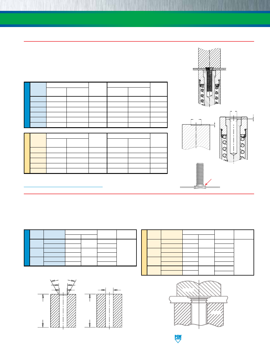
PennEngineering • www.pemnet.com
SS-19
FASTENERS FOR USE IN STAINLESS STEEL SHEETS
INSTALLATION
TYPE TP4
1.
Prepare properly sized mounting hole in sheet. Do not perform any secondary operations such as deburring.
2.
Place pin end through (punched side of) mounting hole in sheet and into anvil as shown
3.
With installation punch and anvil surfaces parallel, apply squeezing force to embed the pin’s head flush in the sheet.
U
NIF
IE
D
Pin Dia.
Test Sheet Anvil Dimensions (in.) Anvil Part Punch Part
Code
Thickness (in.)
A ±.002
C ±.002
Number Number
125
.040 - .060
.160
.130
8003284
Over .060
(1)
8003278
187
.040 - .065
.220
.192
8003285
975200048
Over .065
(1)
8003279
250
.040 - .075
.285
.255
8003286
Over .075
(1)
8003280
(1) Chamfered anvil not required.
PEMSERTER® Installation Tooling
ME
TR
IC
Pin Dia.
Test Sheet Anvil Dimensions (mm)
Anvil Part
Punch Part
Code
Thickness (mm)
A ±0.05
C ±0.05
Number Number
3MM
1 - 1.7
3.88
3.11
8008096
Over 1.7
(1)
8008095
4MM
1 - 1.7
4.88
4.11
8003287
Over 1.7
(1)
8003281
975200048
5MM
1 - 1.8
5.89
5.13
8003288
Over 1.8
(1)
8003282
6MM
1 - 1.9
6.89
6.12
8003289
Over 1.9
(1)
8003283
See page 12
for “L”.
PUNCH
ANVIL
SHEET(S)
BEFORE
AFTER
U
NIF
IE
D
Thread
Punch Dimensions (in.) Punch Anvil Dimensions (in.) Anvil
Code
A
B
Part C P Part
+.004 –.000
+.000 –.001
Number
+.001
+.000 –.002
Number
256 .209 .019 8015111 .087 .014 8016983
440
.248
.022
8015112
.113
.014
8016984
632
.276
.022
8015113
.139
.014
8016985
832
.299
.022
8015114
.165
.014
8016986
032
.327
.022
8015115
.191
.014
8016987
0420
.386
.026
8015116
.251
.014
8016988
ME
TR
IC
Thread
Punch Dimensions (mm) Punch Anvil Dimensions (mm) Anvil
Code
A
B
Part C P Part
+0.1
–0.025
Number +0.025
–0.05
Number
M2.5 5.5 0.47 8015117 2.53 0.35 8016989
M3
6.5
0.57
8015118
3.03
0.35
8016990
M4
7.5
0.57
8015119
4.03
0.35
8016991
M5
8.5
0.57
8015120
5.03
0.35
8016992
M6
9.5
0.67
8015121
6.03
0.35
8016993
Punch pushes over
protruding knurls
1.
2.
3.
NOTE:
For panel design information, go to
http://www.pemnet.com/SGPC_Panel_Designs.pdf
A
B
PUNCH
ANVIL
C
P
150˚
TYPE SGPC
1.
Prepare properly sized mounting hole in sheet.
2.
Insert fastener through mounting hole (punch side) as shown in drawing.
3.
With installation punch and anvil surfaces parallel, apply squeezing force until the
punch pushes over the protruding knurls of the stud.
PEMSERTER® Installation Tooling
PUNCH
SHEET
ANVIL
Recommended tooling when a
chamfered anvil is required.
Recommended tooling when a
chamfered anvil is not required.
60°
Nom.
A
C
C
L +.125”/
3.18mm Min.
L +.125”/
3.18mm Min.
pem-html.html
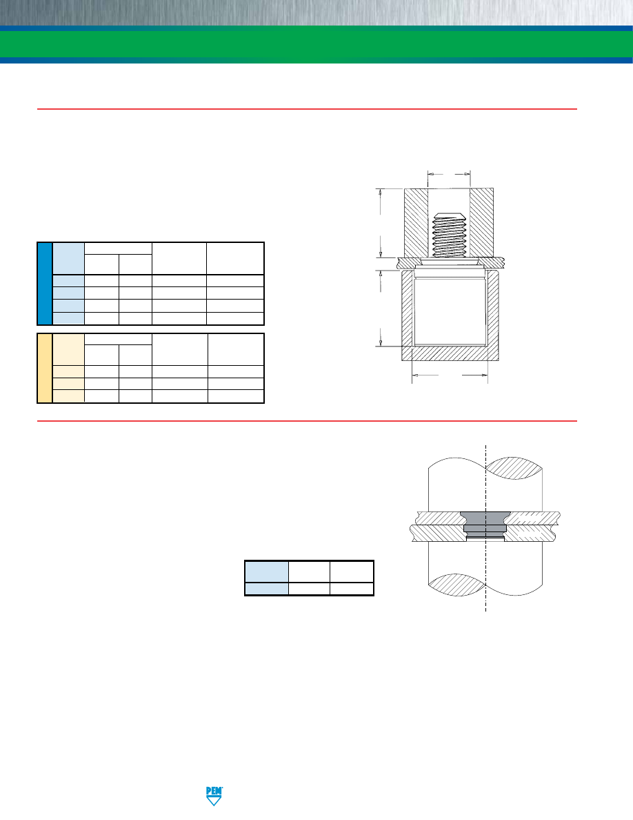
SS-20
PennEngineering • www.pemnet.com
FASTENERS FOR USE IN STAINLESS STEEL SHEETS
INSTALLATION
Panel 1
Panel 2
PUNCH
ANVIL
TYPE SFP
1.
Prepare properly sized mounting hole in both panels. Do not perform any
secondary operations such as deburring.
2.
Place Panel 2 with smaller mounting hole on anvil and align Panel 1 mounting hole
with the mounting hole of Panel 2. Place the smaller diameter end of the fastener
through the mounting holes as shown in the drawing to the right.
3.
With installation punch and anvil surfaces parallel, apply squeezing force until the
fastener is flush with the top of Panel 1.
Anvil Part
Punch Part
Size
Number Number
SF-3 / SF-5
975200046
975200048
PEMSERTER® Installation Tooling
NOTE:
To use as a flush-mounted pivot point,
for best results, install SpotFast fastener
into Panel 1 first, then place Panel 2 over
fastener and squeeze again.
ME
TR
IC
U
NIF
IE
D
TYPE PFC4
1.
Prepare properly sized mounting hole in sheet. Do not perform any
secondary operations such as deburring.
2.
Place fastener into the anvil hole and place the (punch side of) mounting
hole over the shank of the fastener retainer.
3.
With installation punch and anvil surfaces parallel, apply squeezing force
until the shoulder of the retainer comes in contact with the sheet material.
Anvil Dimensions (in.)
Thread
A C
Anvil Part
Punch Part
Code
±.002 ±.002 Number Number
440 .345 .358 975200027 975200060
632
.345
.390
975201243
975200061
832
.435
.421
975200029
975200062
032
.435
.452
975201244
975200064
PEMSERTER® Installation Tooling
Anvil Dimensions (mm)
Thread
A C
Anvil Part
Punch Part
Code
±0.05 ±0.05 Number Number
M3 8.76 9.09 975200027 975200060
M4
11.05
10.69
975200029
975200062
M5
11.05
11.48
975201244
975200064
Thread Dia. +.080”/2mm
PUNCH
G Min.
ANVIL
A
C
See page 13
for “G”.
pem-html.html
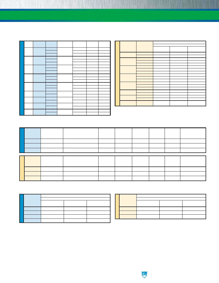
PennEngineering • www.pemnet.com
SS-21
FASTENERS FOR USE IN STAINLESS STEEL SHEETS
PERFORMANCE DATA
(1)
TYPE SP
ME
TR
IC
Test Sheet Material
304 Stainless Steel
Thread
Shank
Installation
Pushout
Torque-out
Code
Code
(kN)
(N)
(N•m)
M2 1 40 725 1.92
2
44.5
1290
2.03
0 35.6 575 1.58
M2.5
1
40
725
1.92
2
44.5
1290
2.03
0 35.6 575 1.58
M3
1
40
725
1.92
2
44.5
1290
2.03
0
40
645
3.38
M4
1
44.5
800
4.18
2
49
1600
5.08
0
42.3
800
3.95
M5
1
46.7
1025
5.08
2
51.2
1775
6.77
M6 1 60 2000 17
2
60
2600
19
M8 1 66 2100 19
2 80 4500 23
M10 1 80 2150 38
(1) Published installation forces are for general reference. Actual set-up and confirmation of complete installation should be made by observing
proper seating of fastener as described in the installation steps. Other performance values reported are averages when all proper installation
parameters and procedures are followed. Variations in mounting hole size, sheet material, and installation procedure may affect performance.
Performance testing this product in your application is recommended. We will be happy to provide technical assistance and/or samples for
this purpose.
(2) Head size is adequate to ensure failure in threaded area when tested with industry standard tensile bushing diameter.
(3) Tightening torque shown will induce preload of 70% of nut min axial strength with K or nut factor is equal to 0.20. In some applications tightening torque
may need to be adjusted based on the actual K value. All tightening torques shown are based on 180 ksi/ Property Class 12.9 screws. For lower strength
screws the tightening torque is proportionately less. For example, for 120 ksi screws, torque is 67% value shown. For 900 MPa screws (Property Class
9.8) torque value is 74% of value shown.
(4) Installation controlled by proper cavity depth in punch.
U
NIF
IE
D
Max. Nut
Test Sheet Thickness
Sheet
Installation
Pushout Torque-out
Tensile
Test Bushing
Thread
Tightening Torque
and Material
Hardness
(lbs.)
(lbs.)
(in. lbs.)
Strength
Hole Size For
Code
(in. lbs.) (2) (3)
(in.)
HRB
(4)
(lbs.) (2) (3)
Pull Thru Tests (in.)
256
7.5
.029” 304 Stainless Steel
89
4500
50
10
640
.104
440
13
.029” 304 Stainless Steel
89
4500
75
15
850
.112
632
20
.029” 304 Stainless Steel
89
6000
75
20
1020
.138
ME
TR
IC
Max. Nut
Test Sheet Thickness
Sheet
Installation
Pushout Torque-out
Tensile
Test Bushing
Thread
Tightening Torque
and Material
Hardness
(kN)
(N) (N•m)
Strength
Hole Size For
Code
(N•m) (2) (3)
(mm)
HRB
(4)
(kN) (2) (3)
Pull Thru Tests (mm)
M2.5
1.05
0.7 mm 304 Stainless Steel
89
20
200
1.35
3.05
3
M3
1.5
0.7 mm 304 Stainless Steel
89
20
300
1.85
3.63
3.5
M3.5
2.1
0.7 mm 304 Stainless Steel
89
27
300
1.9
4.25
4
TYPE SMPP
U
NIF
IE
D
Test Sheet Material
300 Series Stainless Steel
Thread
Installation
Retainer Pushout
Retainer Torque-out
Code
(lbs.)
(lbs.)
(in. lbs.)
440
9000
200
85
632
10000
200
85
832
12000
200
85
032
13000
250
125
TYPES A4/LA4
ME
TR
IC
Test Sheet Material
300 Series Stainless Steel
Thread
Installation
Retainer Pushout
Retainer Torque-out
Code
(kN) (N) (N•m)
M3
40
890
9.6
M4
53
890
9.6
M5
57
1100
14.1
U
NIF
IE
D
Type
Thread
Shank
Test Sheet
Installation
Pushout
Torque-out
Code
Code
Material
(lbs.)
(lbs.)
(in. lbs.)
0
304 Stainless
8000 130 14
SP 256 1
Steel
9000 165 17
2
10000 290 18
0
304 Stainless
8000 130 14
SP 440 1
Steel
9000 165 17
2
10000 290 18
0
304 Stainless
8500 140 18
SP 632 1
Steel
9500 170 24
2
10500 340 28
0
304 Stainless
9000 145 30
SP 832 1
Steel
10000 180 37
2
11000 360 45
0
304 Stainless
9500 180 35
SP 024/032 1
Steel
10500 230 45
2
11500 400 60
SP 0420
1
304 Stainless
13500 450 150
2 Steel 13500 600 170
SP 0518
1
304 Stainless
14800 470 170
2
Steel
14800 750 250
SP 0524
1
304 Stainless
14800
470
170
2 Steel 14800 750 250
SP 0616/0624 1
304 Stainless
16000 600 300
2
Steel 20000 700 370
pem-html.html
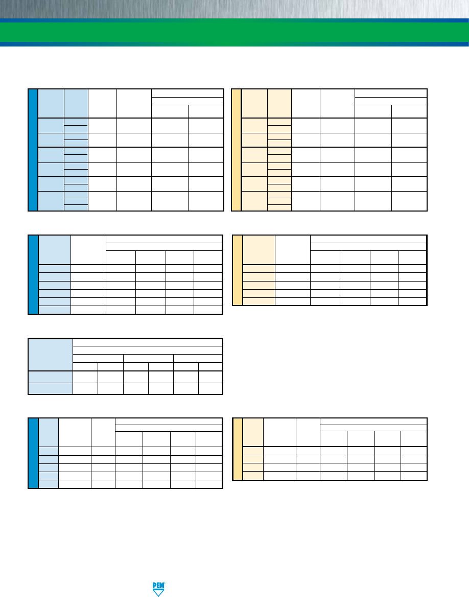
SS-22
PennEngineering • www.pemnet.com
FASTENERS FOR USE IN STAINLESS STEEL SHEETS
TYPE FH4
U
NIF
IE
D
Max. Rec.
Test Sheet Material
Thread Tightening
Sheet
.060” Stainless Steel
(4)
Code
Torque For
Hardness
Mating Screw
HRB
Installation Pushout Torque-out Pull-thru
(in. lbs.)
(lbs.) (lbs.) (in.
lbs.) (lbs.)
440
6
87
9000
450
16
800
632
11
87
9500
540
27
1350
832
21
86
11200
780
58
1800
032
33
86
12000
800
95
2250
0420
70
86
23000
1600
156
3900
ME
TR
IC
Max. Rec.
Test Sheet Material
Thread Tightening
Sheet
1.5 mm Stainless Steel
(4)
Code
Torque For
Hardness
Mating Screw
HRB
Installation Pushout Torque-out Pull-thru
(N•m)
(kN) (N) (N•m) (N)
M3
0.9
87
40
2220
1.8
3500
M4
2.1
86
50
3210
6.5
8000
M5
4.3
86
53
3560
10.7
10000
M6
7.2
86
71
4200
15.9
14900
PERFORMANCE DATA
U
NIF
IE
D
Axial
Max. Screw Test Sheet Material
Thread Shank
Tensile
Tightening 300 Series Stainless Steel
Code Code
Strength Torque
(2)
(lbs.)
(1)
(in. lbs.)
Installation
Pushout
(lbs.)
(lbs.)
256 1 130 1.50 7200 270
2
440 1 165 2.50 7200 270
2
632 1 190 3.50 7200 290
2
832 1 230 5.25 9000 450
2
032 1 280 7.50 9000 450
2
3
0420
4 1035 36
14000 1000
5
ME
TR
IC
Axial
Max. Screw Test Sheet Material
Thread Shank
Tensile
Tightening 300 Series Stainless Steel
Code Code
Strength Torque
(2)
(kN)
(1)
(N•m)
Installation
Pushout
(kN)
(N)
M2 1 0.57 0.16 32 1200
2
M2.5 1 0.68 0.23 32 1200
2
M3 1 0.85 0.36 32 1200
2
M4 1 1 0.58 40 2000
2
M5 1 1.3 0.88 40 2000
2
3
M6
4 4.5 3.7
65 4500
5
TYPE F4
ME
TR
IC
U
NIF
IE
D
Max. Rec.
Test Sheet Material
Thread
Tightening
.050” 300 Series Stainless Steel
Code
Torque For
Mating Screw
Installation Pushout Torque-out Pull-thru
(in. lbs.)
(lbs.)
(lbs.)
(in. lbs.)
(3)
(lbs.)
(3)
440
4.75
5500
336
17
600
6440
4.75
9500
647
30
680
632
8.75
9500
647
30
680
8632
8.75
10500
900
71
1392
832
18
10500
900
71
1517
032
32
10500
900
71
1368
Max. Rec.
Test Sheet Material
Thread
Tightening
1.3 mm 300 Series Stainless Steel
Code
Torque For
Mating Screw
Installation Pushout Torque-out Pull-thru
(N•m)
(kN) (N) (N•m)
(3)
(N)
(3)
M3
0.55
24.5
1493
2.36 2650
3.5M3
0.55
42.3
2877
3.06
3025
M3.5
0.91
42.3
2877
3.06
3025
M4
2
46.7
4003
8.89 6458
M5
3.6
46.7
4003
8.89 6226
TYPES SO4/BSO4
Standoff “C”
Dimension
Installation
Pushout
Torque-out
(3)
(lbs.) (kN) (lbs.) (N) (in.
lbs.) (N•m)
.165” / 4.2 mm
5700
25.4
125
555
13
1.5
.212” / 5.39 mm
6800
30.3
160
710
22
2.5
Test Sheet Material
.025” / 0.64 mm 300 series stainless steel
TYPE TSO4
(1) Failure occurs in screw stripping using a 60 ksi screw and the shortest shank length fastener.
(2) Torque values shown will produce a preload of 70% of axial tensile strength with nut factor “k” equal to .2. Threads may strip or head of the nut may
bend and/or fail if screw is over-torqued beyond these values or if actual k value is less than .2.
(3) Joint failure in torque-out and pull-thru will depend on the strength and type of screw being used. In some cases the failure will be in the screw and not
in the self-clinching standoff. Please contact our Applications Engineering group with any questions.
(4) Performance may be reduced for studs installed into thicker sheets.
pem-html.html
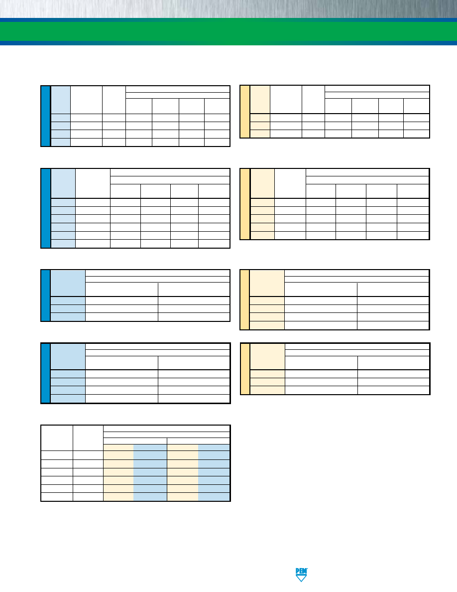
PennEngineering • www.pemnet.com
SS-23
FASTENERS FOR USE IN STAINLESS STEEL SHEETS
TYPE PFC4
ME
TR
IC
U
NIF
IE
D
Test Sheet Material
300 Series Stainless Steel
Thread
Installation
Retainer Pushout
Code
(lbs.) (lbs.)
440
9100
350
632
10300
400
832
10800
450
032
11800
550
Test Sheet Material
300 Series Stainless Steel
Thread
Installation
Retainer Pushout
Code
(kN) (N)
M3
40.5
1557
M4
48
2002
M5
52.5
2447
PERFORMANCE DATA
(1) Performance may be reduced for studs installed into thicker sheets.
(2) In most applications, pullout strength of the SpotFast fastener in Panel 1 exceeds pushout strength of Panel 2.
TYPE FHP
U
NIF
IE
D
Max. Rec.
Test Sheet Material
Thread Tightening
Sheet
.060” Stainless Steel
(1)
Code
Torque For
Hardness
Mating Screw
HRB
Installation Pushout Torque-out Pull-thru
(in. lbs.)
(lbs.) (lbs.) (in.
lbs.) (lbs.)
440
6
86
9000
520
10.6
605
632
11
86
9500
670
19.5
940
832
21
86
11200
785
37.5
1415
032
33
86
12000
800
59.5
1500
ME
TR
IC
Max. Rec.
Test Sheet Material
Thread Tightening
Sheet 1.5 mm (for M4&M5) 2 mm (for M3) Stainless Steel
(1)
Code
Torque For
Hardness
Mating Screw
HRB
Installation Pushout Torque-out Pull-thru
(N•m)
(kN) (N) (N•m) (N)
M3
1.3
86
40
2500
1.6
3500
M4
2.1
86
50
3000
3.9
6000
M5
4.3
86
53
3560
7.35
7320
ME
TR
IC
U
NIF
IE
D
U
NIF
IE
D
ME
TR
IC
TYPE SGPC
Max. Rec.
Test Sheet Material
Thread
Tightening Single sheet of .039” 300 Series Stainless Steel
Code
Torque For
Mating Nut
Installation
Pushout
Torque-out
Pull-thru
(in. lbs.)
(lbs.)
(lbs.)
(in. lbs.)
(lbs.)
256
2.3
4000
425
5.2
415
440
5
5000
450
8
512
632
9
5500
460
15.8
811
832
17
6500
480
29.3
1133
032
27
7300
545
42.8
1273
0420
58
10000
565
76.7
1721
Max. Rec.
Test Sheet Material
Thread
Tightening Single sheet of 1 mm 300 Series Stainless Steel
Code
Torque For
Mating Nut
Installation
Pushout
Torque-out
Pull-thru
(N•m)
(kN)
(N)
(N•m)
(N)
M2.5
0.41
20.1
2546
0.86
2561
M3
0.74
21.8
2051
1.35
2851
M4
1.7
28.5
2396
2.66
4000
M5
3.5
35.6
3200
5.96
4284
M6
5.9
42.3
3262
9.19
6311
Test Sheet Material
Pin 300 Series Stainless Steel
Diameter
Installation Pushout
Code
(lbs.) (lbs.)
125
8000
350
187
12000
570
250
14000
650
TYPE TP4
Test Sheet Material
Pin 300 Series Stainless Steel
Diameter
Installation Pushout
Code
(kN) (N)
3MM
35
1556
4MM
45
2335
5MM
54
2535
6MM
60
2891
Test Sheet Material
Type and Thickness
Stainless
Steel
Size
Code
Installation
Pushout of Panel 2
(2)
kN lbs. N lbs.
SFP-3
1.0
13.5 3000 620 140
SFP-3
1.2
20 4500 830 186
SFP-3
1.6
22 5000 1500 340
SFP-5
1.0
18 4000 990 222
SFP-5
1.2
27 6000 1158 260
SFP-5
1.6
33 7500 3117 701
TYPE SFP
pem-html.html
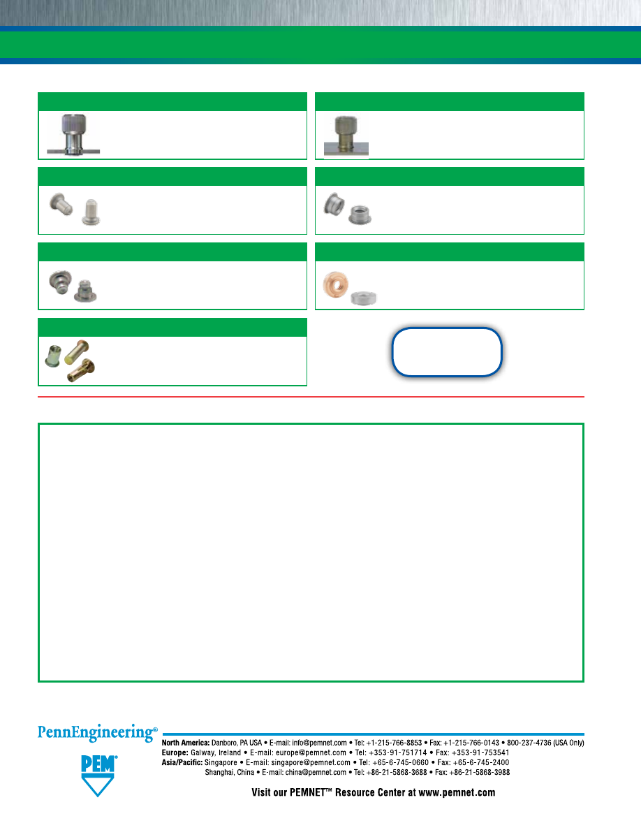
SS-24
FASTENERS FOR USE IN STAINLESS STEEL SHEETS
Technical support e-mail: techsupport@pemnet.com
Specifications subject to change without notice.
See our website for the most current version of this bulletin.
Regulatory compliance information is available in Technical
Support section of our website. © 2016 PennEngineering.
OTHER FASTENERS FOR CONSIDERATION TO USE IN STAINLESS STEEL SHEETS
Type PF11MW™
Type PF11MF™
Floating captive panel screw with unique flare-
mount feature allows fastener to “float” in mounting
hole and compensate for mating thread alignment.
(See PEM® Bulletin PF)
Type WN/WNS
Type MPP™
Self-clinching microPEM® pins that can be installed
into stainless steel sheets as thin as .02”/0.5mm.
(See PEM® Bulletin MPF)
Type MSO4™
Self-clinching microPEM® standoffs that can be
installed into stainless steel sheets as thin as
.016”/0.4mm.
(See PEM® Bulletin MPF)
ATLAS® BLIND THREADED INSERTS
Attach to panels of any hardness and provide
strong and reusable permanent threads in sheet
materials where only one side is accessible.
(See ATLAS® Catalog)
Flare-mounted captive panel screw that installs
into any panel material and is flush on back side
of panel.
(See PEM® Bulletin PF)
Designed to overcome many problems such as
burn-outs, complicated electrodes and pilots,
indexing and re-tapping to remove weld spatter.
(See PEM® Bulletin WN)
Type T4™
microPEM® TackPin® fasteners enable sheet-
to-sheet attachment in stainless steel sheets in
applications where disassembly is not required.
(See PEM® Bulletin MPF)
“Dos”
DO
select the proper fastener material to meet corrosion requirements.
DO
make certain that panel material is in the annealed condition.
DO
make certain that hole punch is kept sharp to minimize work hardening around hole.
DO
provide mounting hole of specified size for each fastener.
DO
maintain the hole punch diameter to no greater than +.001”/.025 mm over the minimum recommended mounting hole.
DO
make certain that fastener is properly positioned within hole before applying installation force.
DO
make certain that fastener is not installed adjacent to bends or other highly cold-worked areas.
DO
apply squeezing force between parallel surfaces.
DO
utilize recommended installation tooling when installing fasteners.
DO
install fastener in punched side of hole.
DO
apply sufficient force to totally embed clinching ring (where applicable) around entire circumference and to bring shoulder squarely in contact with sheet. For all other fasteners, installation
will be complete when the head is flush with the panel surface.
“Don’ts”
DON’T
attempt to install a 300 series stainless steel fastener into a stainless steel sheet.
DON’T
deburr mounting holes on either side of sheet before installing fasteners – deburring will remove metal required for clinching fastener into sheet.
DON’T
install fastener closer to edge of sheet than minimum edge distance – unless a special fixture is used to restrict bulging of sheet edge.
DON’T
install fastener near bends or other highly cold worked areas where sheet hardness may be greater than the limit for the fastener.
DON’T
over-squeeze. It will crush the head, distort threads, and buckle the sheet. Be certain to determine optimum installation force by test prior to production runs.
DON’T
attempt to insert fastener with a hammer blow – under any circumstances. A hammer blow won’t permit the sheet metal to flow and develop an interlock with the fastener’s contour.
DON’T
install screw in the head side of fastener. Install from opposite side so that the fastener load is toward sheet. The clinching force is designed only to hold the fastener during handling and
to resist torque during assembly.
INSTALLATION INTO STAINLESS STEEL SHEETS DOS AND DON’TS
Fastener drawings and
models are available at
www.pemnet.com
pem-html.html
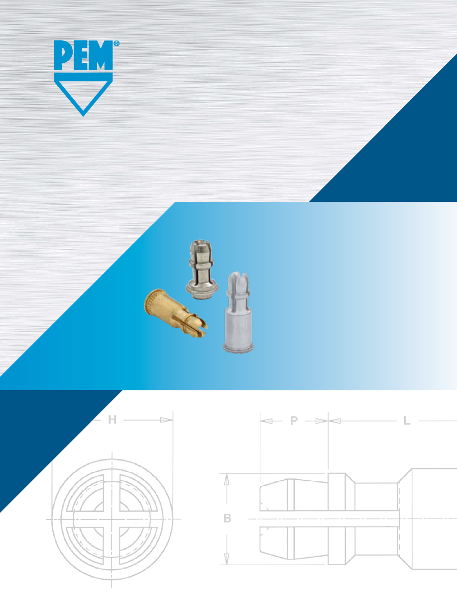
SSA
™
SNAP-TOP®
STANDOFFS
PEM® brand SNAP-TOP® standoffs are
designed for permanent installation
into metal panels or PC Boards
Bulletin SSA-516
REV 817
pem-html.html
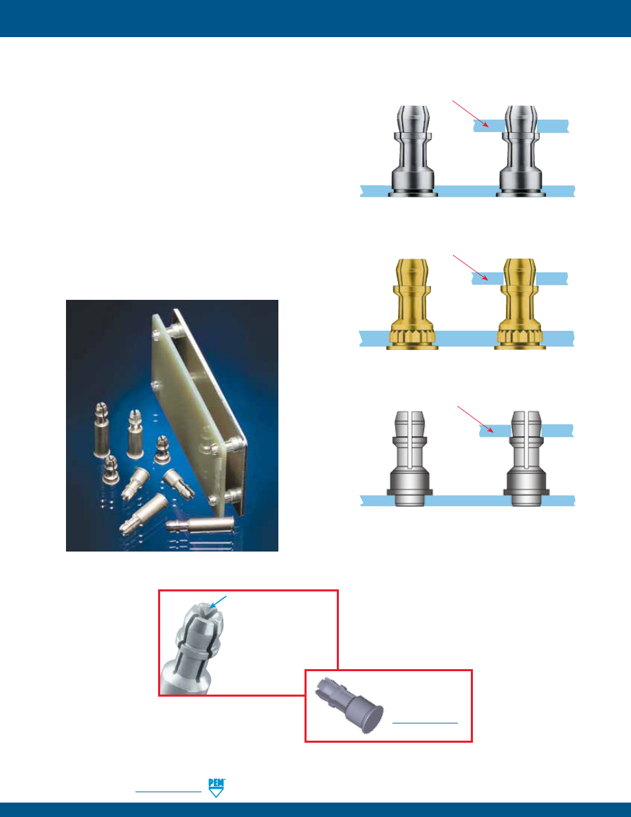
SSA-2
PennEngineering •
www.pemnet.com
To be sure that you are
getting genuine PEM®
brand SNAP-TOP®
standoffs, look for the
“dimple” registered
trademark.
PC board or metal panel snapped in place
SSA™/SSS™/SSC™ standoffs
clinched
into a metal panel
Fastener drawings
and models
are available at
www.pemnet.com
PEM SNAP-TOP® Standoffs are designed for permanent
installation into metal panels or PC boards.
•
Spring action to hold PC Boards and subassemblies securely.
•
Allows for quick removal.
•
Eliminates screws and other threaded hardware.
–
Less parts to handle during assembly.
–
Less risk of damaging delicate circuitry because of
loose parts falling into your equipment.
•
Available in three different mounting styles:
–
Self-clinching
–
Broaching
–
Surface mount
•
Permanently installed in the panel.
Installation forces, pushout and snap forces are listed on page 7.
SNAP-TOP® STANDOFFS
KSSB™ standoffs
broached
into a PC board
PC board or metal panel snapped in place
SSTSS™ standoffs
surface mounted
into PC Board
PC board or metal panel snapped in place
pem-html.html
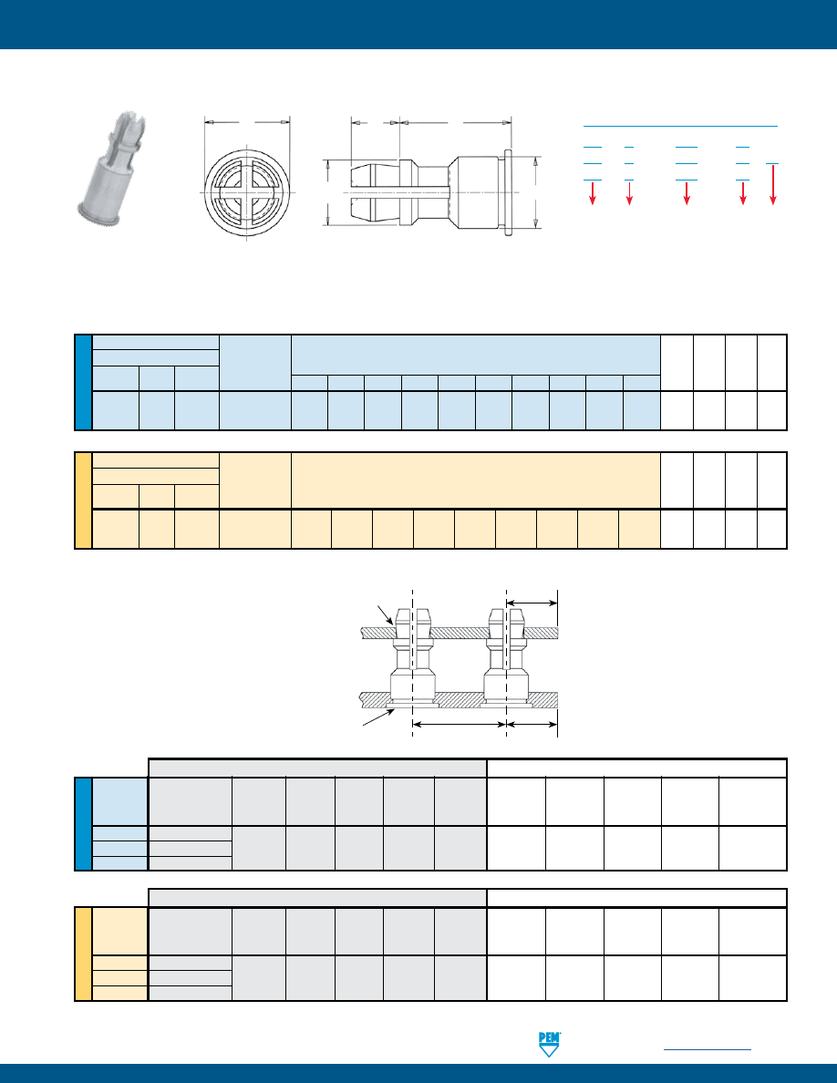
PennEngineering •
www.pemnet.com
SSA-3
ME
TR
IC
U
NIF
IE
D
Type
Fastener Material
Panel
2
(Top) B C
H
P
Aluminum Carbon Stainless
Mounting
Hole
±.005
Max.
±.005
±.005
Steel Steel
Diameter Code
SSA SSS SSC
156
8 10 12 14 16 18 20 24 28 32 .188 .212 .250 .141
H
P
L
C
B
FASTENER MATERIAL:
FINISH:
SSA: Aluminum
SSA: Natural
SSS: Lead-free Carbon Steel
SSS: ZI - Zinc plated, 5µm, colorless, plus clear chromate
(1)
SSC: 400 Series Stainless Steel
SSC: Passivated and/or tested per ASTM A380
Type
Fastener Material
Panel
2
(Top) B
C
H
P
Aluminum Carbon Stainless
Mounting
Hole
±0.13
Max.
±0.13
±0.13
Steel Steel
Diameter Code
SSA SSS SSC
4MM
8
10
12
14
16
18
20
22
25 4.78 5.39 6.35 3.58
Length Code “L” ±.005
(Length Code in 32nds of an inch)
Length Code “L” ±0.13
(Length Code in millimeters)
(1) See PEM Technical Support section of our web site for related plating standards and specifications.
SS
A - 156 - 10
SS
S - 156 - 10 ZI
SS
C - 156 - 10
Type
PART NUMBER DESIGNATION
Mounting Hole A
Diameter Code
Length
Code
Material
Finish
.250 .312 .375 .437 .500 .562 .625 .750 .875 1.00
SNAP-TOP® STANDOFFS
SSA™/SSS™/SSC™ STANDOFFS FOR CLINCHING INTO METAL SHEETS
All dimensions are in inches.
All dimensions are in millimeters.
Mounting Hole A
Mounting Hole B
Location
Tolerance
Edge
C1
Edge
C2
PANEL 2 (TOP)
PANEL 1 (BOTTOM)
U
NIF
IE
D
ME
TR
IC
Bottom
Edge
Top Edge
Hardness
Mounting Panel Thickness Distance
Location Hardness Mounting Panel Thickness
Distance
Type
Max.
Hole B
Material
Min.
C
1
Min.
Tolerance
Max.
Hole A
Material
Range
C
2
Min.
(2)
+.003 -.000
+.003 -.000
(3)
SSA
HRB 50 / HB 82
PC Board
SSS
HRB 60 / HB 107
.213
Metal .040 .260 ±.005 No Limit .156 or Metal
.040 - .070
.100
SSC
HRB 70 / HB 125
Panel 1
Panel 2
Bottom
Edge
Top Edge
Hardness
Mounting Panel Thickness Distance
Location Hardness Mounting Panel Thickness
Distance
Type
Max.
Hole B
Material
Min.
C
1
Min.
Tolerance
Max.
Hole A
Material
Range
C
2
Min.
(2) +0.08 +0.08 (3)
SSA
HRB 50 / HB 82
PC Board
SSS
HRB 60 / HB 107
5.41
Metal 1 6.6 ±0.13 No Limit 4 or Metal
1 - 1.8
2.54
SSC
HRB 70 / HB 125
Panel 1
Panel 2
All dimensions are in inches.
All dimensions are in millimeters.
APPLICATION DATA
(2)
HRB - Hardness Rockwell “B” Scale. HB - Hardness Brinell.
(3)
Available for thicker boards on special order.
pem-html.html
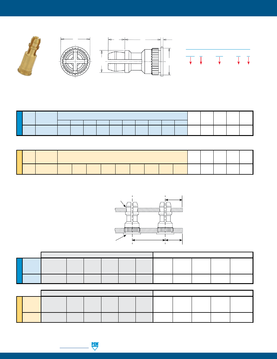
SSA-4
PennEngineering •
www.pemnet.com
ME
TR
IC
U
NIF
IE
D
Panel 2 (Top)
B C H P T
Type
Mounting Hole
±.005
±.003
±.005
±.005
±.005
Diameter Code
KSSB 156 8 10 12 14 16 18 20 24 28 32 .188 .226 .250 .141 .020
Panel 2 (Top)
B
C
H
P
T
Type
Mounting Hole
±0.13
±0.08
±0.13
±0.13
±0.13
Diameter Code
KSSB 4MM
8 10
12
14
16
18 20 22 25 4.78 5.74 6.35 3.58 0.51
FASTENER MATERIAL:
FINISH:
Free Machining Brass
Standard: X - Plain
Optional: ET - Electro-plated Tin, ASTM B545 Class B (5µm) with preservative coating, annealed
(1)
(Optional ET finish is available on special order with additional charge.)
H
P
L
T
C
B
Length Code “L” ±.005
(Length Code in 32nds of an inch)
Length Code “L” ±0.13
(Length Code in millimeters)
KSSB™ STANDOFFS FOR BROACHING INTO PC BOARDS
.250 .312 .375 .437 .500 .562 .625 .750 .875 1.00
(1) See PEM Technical Support section of our web site for related plating standards and specifications.
SNAP-TOP® STANDOFFS
KSS B - 156 - 10 X
Type
PART NUMBER DESIGNATION
Mounting Hole A
Diameter Code
Length
Code
Material
Finish
All dimensions are in inches.
All dimensions are in millimeters.
(2)
HRB - Hardness Rockwell “B” Scale. HB - Hardness Brinell.
(3)
Available for thicker boards on special order.
ME
TR
IC
U
NIF
IE
D
Bottom Edge
Top Edge
Hardness Mounting Panel Thickness Distance
Location
Hardness Mounting Panel Thickness
Distance
Type
Max.
Hole B
Material
Min.
C
1
Min.
Tolerance
Max.
Hole A
Material
Range
C
2
Min.
(2)
+.003 -.000
+.003 -.000
(3)
KSSB
HRB 65 / HB 116
.213
PC Board .050 .220 ±.005 No Limit
.156
PC Board
.040 - .070
.100
or Metal
Panel 1
Panel 2
Bottom Edge
Top Edge
Hardness Mounting Panel Thickness Distance
Location
Hardness Mounting Panel Thickness
Distance
Type
Max.
Hole B
Material
Min.
C
1
Min.
Tolerance
Max.
Hole A
Material
Range
C
2
Min.
(2) +0.08 +0.08 (3)
KSSB
HRB 65 / HB 116
5.41
PC Board 1.27 5.59 ±0.13 No Limit 4 PC Board
1 - 1.8
2.54
or Metal
Panel 1
Panel 2
All dimensions are in inches.
All dimensions are in millimeters.
APPLICATION DATA
Mounting Hole A
Mounting Hole B
Location
Tolerance
Edge
C1
Edge
C2
PANEL 2 (TOP)
PANEL 1 (BOTTOM)
pem-html.html
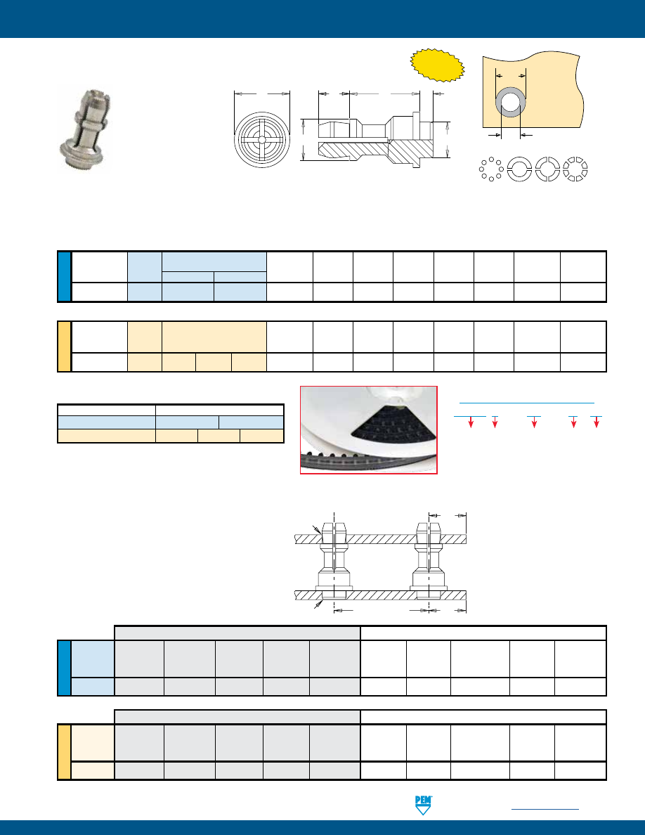
PennEngineering •
www.pemnet.com
SSA-5
SNAP-TOP® STANDOFFS
SMTSS™ REELFAST® SNAP-TOP® STANDOFFS
Ø
H
Ø
D
Solder
Pad
Plated through hole
not required.
NUMBER OF PARTS PER REEL
Packaged on 330 mm recyclable reels. Tape width is 24 mm.
Supplied with polyimide patch for vacuum pick up.
Reels conform to EIA-481.
E
P
L
A
C
B
U
NIF
IE
D
Top
Board
Min.
ØH
Hole
ØD
Mounting Hole
Type and
Sheet
A
C
E
B
P
Size in Sheet
Min.
Diameter Code
Material
.250 .375
Thickness
Max.
Max.
±.005
±.005
±.005
+.003 –.000
Solder Pad
156 SMTSSS 8
12
.060 .060 .161 .250 .188 .141
.166
.276
Length Code “L” ±.005
(Length Code in 32nds of an inch)
All dimensions are in inches.
ME
TR
IC
Top
Board
Min.
ØH
Hole
ØD
Mounting Hole
Type and
Sheet
A
C
E
B
P
Size in Sheet
Min.
Diameter Code
Material
Thickness Max. Max. ±0.13 ±0.13 ±0.13 +0.08 Solder
Pad
4MM SMTSSS 6
8 10
1.53
1.53 4.09 6.35 4.8 3.58
4.22
7
Length Code “L” ±0.13
(Length Code in millimeters)
All dimensions are in millimeters.
Type, Material and Size Length Code / Number of Parts per Reel
SMTSSS-156
-8 / 280
-12 / 220
SMTSSS-4MM
-6 / 300
-8 / 250
-10 / 200
SMTSS S – 156 – 12 ET
PART NUMBER DESIGNATION
Mounting Hole A
Diameter Code
Length
Code
Finish
Type Material
Stencil Masking Examples
NEW!
NOTE:
REELFAST®
SNAP-TOP® SMTSS™
standoffs are for on-only
applications. For removal
applications, mounting
hole A can be increased
to reduce removal force.
APPLICATION DATA
U
NIF
IE
D
Bottom
Top
Edge
Hardness Mounting Panel Thickness
Location Hardness Mounting
Panel
Thickness
Distance
Type
Max.
Hole B
Material
Min.
Tolerance
Max.
Hole A
Material
Range
C Min.
+.003 -.000
+.003 -.000
SMTSS
No Limit
.166
P.C. Board
.060
±.005
No Limit
.156
P.C. Board or Metal
.040 - .070
.100
Panel 1
Panel 2
All dimensions are in inches.
ME
TR
IC
Bottom
Top
Edge
Hardness Mounting Panel Thickness
Location Hardness Mounting
Panel
Thickness
Distance
Type
Max.
Hole B
Material
Min.
Tolerance
Max.
Hole A
Material
Range
C Min.
+0.08
+0.08
SMTSS
No Limit
4.22
P.C. Board
1.53
±0.13
No Limit
4
P.C. Board or Metal
1 - 1.8
2.54
Panel 1
Panel 2
All dimensions are in millimeters.
FASTENER MATERIAL:
FINISH:
Lead-free Carbon Steel
ET - Electro-plated Tin, ASTM B545 Class A with clear preservative coating, annealed
(1)(2)
(
1) See PEM Technical Support section of our web site for related plating standards and specifications.
(2) Optimal solderability life noted on packaging.
Mounting Hole A
Mounting Hole B
Location Tolerance
Edge
C
PANEL 2 (TOP)
PANEL 1 (BOTTOM)
pem-html.html
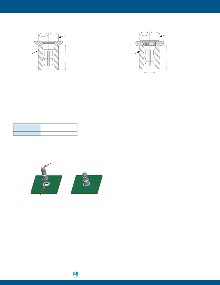
SSA-6
PennEngineering •
www.pemnet.com
SNAP-TOP® STANDOFFS
SSA™/SSS™/SSC™ Standoffs
1.
Prepare properly sized mounting hole in Panel 1 (Bottom).
2.
Place the fastener through the mounting hole (preferably the punch
side) of the panel and into the anvil as shown in the drawing.
3.
With punch and anvil surfaces parallel, apply only enough
squeezing force to embed the head flush with the panel.
INSTALLATION
PANEL 1 (Bottom)
.216-.219” /
5.49-5.56mm
L + .200”/
5.08mm MIN.
PUNCH
ANVIL
PANEL 1 (Bottom)
.216-.219” /
5.49-5.56mm
PUNCH
L + .200”/
5.08mm MIN.
ANVIL
Type
Anvil Part
Punch Part
Number Number
SSA, SSS, SSC, KSSB
970200015300
975200048
PEMSERTER® Installation Tooling
KSSB™ Standoffs
1.
Prepare properly sized mounting hole in Panel 1 (Bottom).
2.
Place the fastener through the mounting hole of the board and
into the anvil as shown in the drawing.
3.
With punch and anvil surfaces parallel, apply only enough
squeezing force to bring the head into contact with the board.
Solder paste applied
to pad on PCB.
Solder fastener in place using
standard surface mount techniques.
Polyimide patch applied
here for vacuum pick up.
SMTSS™ Standoffs
pem-html.html
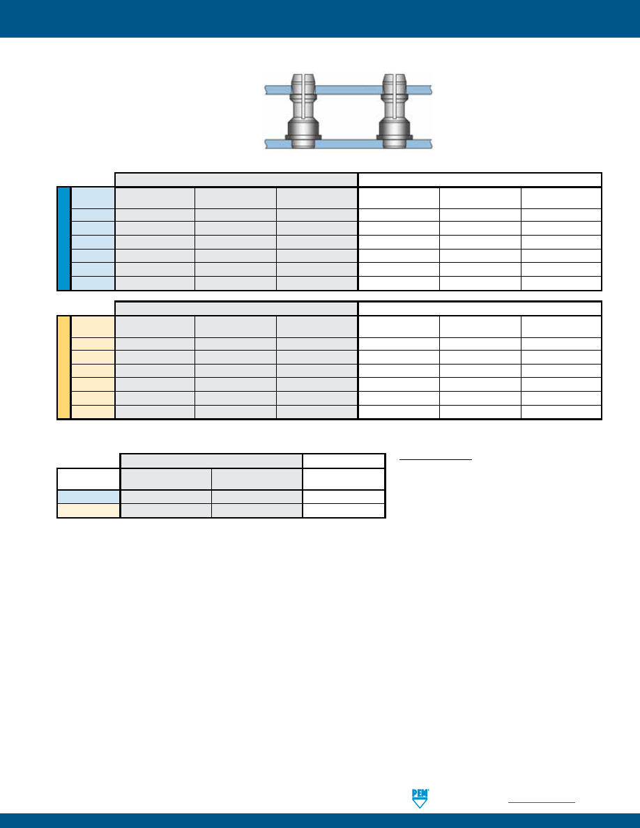
PennEngineering •
www.pemnet.com
SSA-7
SNAP-TOP® STANDOFFS
ME
TR
IC
U
NIF
IE
D
(1) Published installation forces are for general reference. Actual set-up and confirmation of complete installation should be made by
observing proper seating of fastener as described in the installation steps. Other performance values reported are averages when all
proper installation parameters and procedures are followed. Variations in mounting hole size, sheet material, and installation procedure
may affect performance. Performance testing this product in your application is recommended. We will be happy to provide technical
assistance and/or samples for this purpose.
(2) With lead-free paste. Average values of 30 test points. The data presented here is for general comparison purposes only. Actual performance is
dependent upon application variables. We will be happy to provide samples for you to install. If required, we can also test your installed hardware and
provide you with the performance data specific to your application.
Type
Test Sheet Material
Installation
Pushout Max. First on Snap Force
Min. First off Snap Force
Min. 15th off Snap Force
(lbs.) (lbs.) (lbs.) (lbs.) (lbs.)
SSA
Aluminum
1500
200
13
3
1
SSS
Aluminum
1500
200
20
6
2
SSC
Aluminum
1500
200
20
6
2
SSS
Cold-rolled Steel
3600
400
20
6
2
SSC
Cold-rolled Steel
3600
400
20
6
2
KSSB
FR-4
Fiberglass
500 110 13 3 1
Panel 1 (Bottom)
Panel 2 (Top)
(Removable)
Type
Test Sheet Material
Installation Pushout
Max. First on Snap Force
Min. First off Snap Force
Min. 15th off Snap Force
(kN) (N) (N) (N) (N)
SSA
Aluminum
6.7
890
58
13
4
SSS
Aluminum
6.7
890
89
27
9
SSC
Aluminum
6.7
890
89
27
9
SSS
Cold-rolled Steel
16
1780
89
27
9
SSC
Cold-rolled Steel
16
1780
89
27
9
KSSB
FR-4 Fiberglass
2.2
484
58
13
4
Panel 1 (Bottom)
Panel 2 (Top)
(Removable)
PERFORMANCE DATA
(1)
TESTING CONDITIONS
Oven
Quad ZCR convection oven with 4 zones
High Temp
473˚F / 245˚C
Board Finish
62% Sn, 38% Pb
Board
.062" / 1.58 mm thick, Single Layer FR-4
Screen Printer
Ragin Manual Printer
Vias
None
Spokes
2 Spoke Pattern
Paste
Alpha CVP-390 Sn96.5/3.0Ag/0.5Cu (SAC305)
Stencil
.0067” / 0.17 mm thick
Type, Material
Test Sheet Material
Pushout (2)
Max. Snap-on Force
and Size
SMTSSS-156
.062" Single Layer FR-4
113 lbs.
20 lbs.
SMTSSS-4MM
1.58 mm Single Layer FR-4
500 N
89 N
Panel 1 (Bottom)
Panel 2 (Top)
SMTSS™ Standoffs
SSA™/SSS™/SSC™/KSSB™ Standoffs
Panel 2 (Top)
Panel 1 (Bottom)
pem-html.html

SSA-8
All PEM® products meet our stringent quality standards. If you require additional industry or other specific
quality certifications
, special procedures and/or part
numbers are required. Please contact your local sales office or representative for further information.
Regulatory
compliance information
is available in Technical Support section of our website. Specifications subject to change without notice. See our website for the
most current version of this bulletin.
North America:
Danboro, Pennsylvania USA
•
E-mail:
info@pemnet.com
•
Tel: +1-215-766-8853
•
800-237-4736 (USA)
Europe:
Galway, Ireland
•
E-mail:
europe@pemnet.com
•
Tel: +353-91-751714
Asia/Pacific:
Singapore
•
E-mail:
singapore@pemnet.com
•
Tel: +65-6-745-0660
Shanghai, China
•
E-mail:
china@pemnet.com
•
Tel: +86-21-5868-3688
Visit our PEMNET™ Resource Center at
www.pemnet.com
•
Technical support e-mail:
techsupport@pemnet.com
SNAP-TOP® STANDOFFS
pem-html.html
SELF-CLINCHING TY-D® CABLE
TIE-MOUNTS AND HOOKS
TD
™
517
BULLETIN
pem-html.html
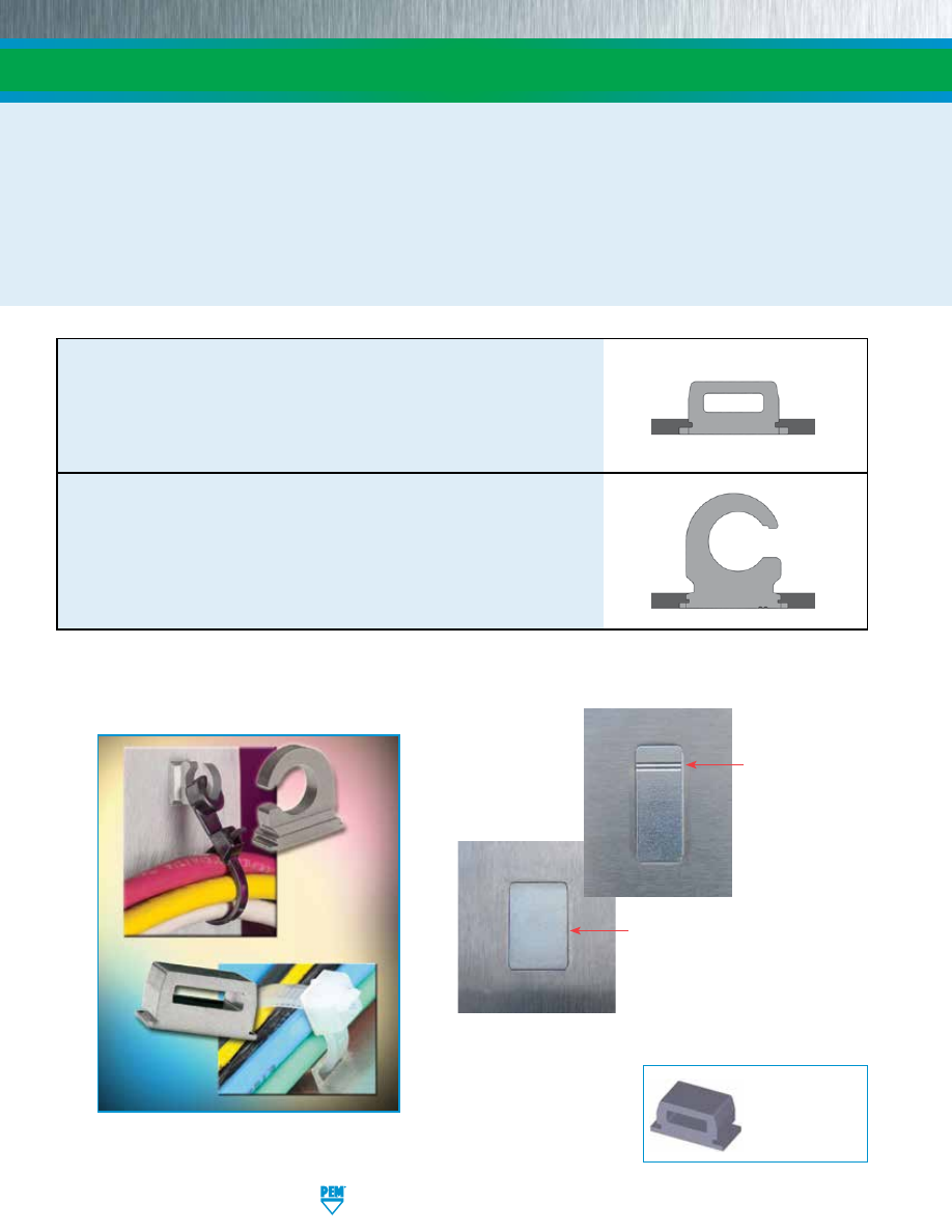
Reverse side of TD™
mounts installed in sheet.
PEM® TY-D® self-clinching tie-mounts and hooks provide secure metal attachment points for mounting wires to electronic
chassis or enclosures. All TY-D hardware installs quickly and permanently without screws and eliminates the use of
adhesives that typically fail over time and temperature cycling.
TY-D hardware can be a great improvement over traditional mounting methods. They can be placed with assurance at
designed locations and angles to remain secure for the life of the assembly; they will not protrude on the reverse side and
will not affect the reverse side appearance or clearance; and panels remain flush.
SELF-CLINCHING TY-D® CABLE TIE-MOUNTS AND HOOKS
Reverse side of TDO™
hooks installed in sheet.
Depending on placement of the
fastener within the mounting hole,
a slight gap may be noticeable
along the non-clinching edges of
the fastener after installation.
TD-2
PennEngineering • www.pemnet.com
TD™ cable tie-mounts
allow users to easily slide ties through the hardware’s
“eye” for fast cable mounting.
TDO™ cable tie hooks
enable users to attach, remove, and return tie-bundled
wires to their mounting points when components need to be accessed for
service or when wires must be replaced. The hook feature allows ties to remain
intact and wires to remain wrapped.
TDO™ hooks open
end orientation mark.
Fastener drawings
and models are
available at
www.pemnet.com
pem-html.html
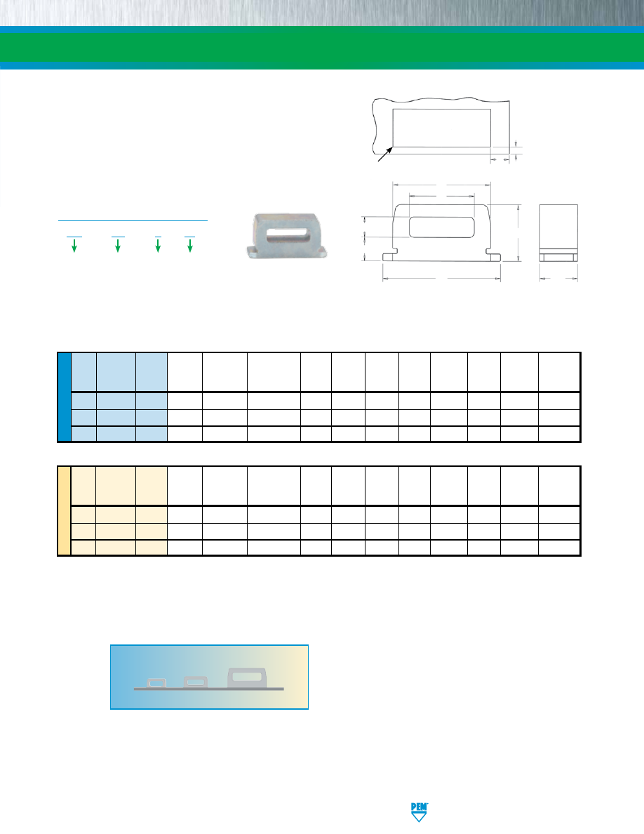
ME
TR
IC
U
NIF
IE
D
Length Hole Size Height
Min. Hole
Min. Hole
Type Profile Length L
Sheet
In Sheet A B C D E G
Edge To
Edge To
(1) Code
±.003 Thickness +.002 -.001 ±.003 ±.006 ±.006 ±.006 ±.006 ±.006
Sheet Edge Sheet Edge
K M
TD
40
4
.121
.040 - .050
.250 x .125
.246
.055
.065
.160
.308
.150
.040
.147
TD
60
6
.184
.040 - .070
.312 x .187
.308
.075
.065
.205
.370
.180
.040
.196
TD
175
12
.371
.040 - .125
.500 x .375
.496
.130
.095
.360
.562
.285
.040
.262
Length Hole Size Height
Min. Hole
Min. Hole
Type Profile Length L
Sheet
In Sheet A B C D E G
Edge To
Edge To
(1) Code
±0.08
Thickness
+0.05 –0.03 ±0.08 ±0.15 ±0.15 ±0.15 ±0.15 ±0.15
Sheet Edge Sheet Edge
K M
TD
40
4
3.07
1.02 - 1.27
6.35 x 3.18
6.25
1.4
1.65
4.06
7.82
3.81
1.02
3.73
TD
60
6
4.67
1.02 -1.78
7.93 x 4.75
7.82
1.91
1.65
5.21
9.4
4.57
1.02
4.98
TD
175
12
9.42
1.02 - 3.18
12.7 x 9.53
12.6
3.3
2.4
9.14
14.28
7.24
1.02
6.65
40
60
175
Profile Shown Actual Size.
(1) Reference to typical load rating (in pounds)
for appropriate size nylon cable tie.
SELF-CLINCHING TY-D® CABLE TIE-MOUNTS AND HOOKS
All dimensions are in inches.
All dimensions are in millimeters.
TD™ CABLE TIE-MOUNTS
PennEngineering • www.pemnet.com
TD-3
TD – 60 – 6
ZI
Type
PART NUMBER DESIGNATION
Profile
Length
Code
Finish
Code
L
C
B
E
G
D
A
M
K
Hole In Sheet
.005”/0.13mm R Max.
(TYP.)
Clinching profile may vary.
Material:
Sintered Steel
Finish:
ZI- Zinc plated, 5µm, colorless. See PEM Technical Support
section of our website for related plating standards and specifications.
For use in sheet hardness:
HRB 60 (Hardness Rockwell “B” scale) /
HB 107 (Hardness Brinell) or less.
pem-html.html
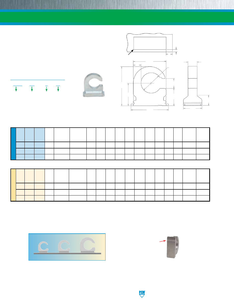
ME
TR
IC
U
NIF
IE
D
40
50
120
Profile Shown Actual Size.
TDO™ hooks open end
orientation mark.
Length Hole Size
Height Min. Hole
Min. Hole
Type Profile Length L
Sheet
In Sheet A B ØC D E F G H I J Edge To
Edge To
(1) Code ±0.08 Thickness +0.05 –0.03 ±0.08 ±0.15 ±0.15 ±0.15 ±0.15 ±0.13 Nom. ± 0.25 ± 0.25 Nom. Sheet Edge Sheet Edge
K M
TDO
40
8
6.25
1.02 - 3.94
6.35 x 9.53
9.42
5.41
6.22
3.3
11
7.24
11.96
3.05
3.3
2.11
1.02
3.73
TDO
50
8
6.25
1.02 - 3.94
6.35 x 11.13
11.02
5.79
6.86
3.3
12.6
7.62
13.13
3.05
3.3
2.59
1.02
4.98
TDO
120
8
6.25
1.02 - 3.94
6.35 x 14.27
14.17
6.48
8.64
3.56
15.75
8.51
15.6
3.05
3.3
3.53
1.02
6.65
Length Hole Size
Height Min. Hole
Min. Hole
Type Profile Length L
Sheet
In Sheet A B ØC D E F G H I J Edge To
Edge To
(1) Code
±.003 Thickness +.002 -.001 ±.003 ±.006 ±.006 ±.006 ±.006 ±.005
Nom. ±.010 ±.010 Nom. Sheet Edge Sheet Edge
K M
TDO
40
8
.246
.040 - .155
.250 x .375
.371
.213
.245
.130
.433
.285
.471
.12
.13
.083
.040
.147
TDO
50
8
.246
.040 - .155
.250 x .438
.434
.228
.270
.130
.496
.300
.517
.12
.13
.102
.040
.196
TDO
120
8
.246
.040 - .155
.250 x .562
.558
.255
.340
.140
.620
.335
.614
.12
.13
.139
.040
.262
(1) Reference to typical load rating (in pounds) for appropriate size nylon cable tie.
SELF-CLINCHING TY-D® CABLE TIE-MOUNTS AND HOOKS
All dimensions are in inches.
All dimensions are in millimeters.
TDO™ CABLE TIE HOOKS
PennEngineering • www.pemnet.com
TD-4
TDO – 50 – 8
ZI
Type
PART NUMBER DESIGNATION
Profile
Length
Code
Finish
Code
I
L
H
E
B
D
A
G
ØC
K
M
Hole In Sheet
J
F
Clinching profile may vary.
.005”/0.13mm R Max.
(TYP.)
Material:
Sintered Steel
Finish:
ZI- Zinc plated, 5µm, colorless. See PEM Technical Support
section of our website for related plating standards and specifications.
For use in sheet hardness:
HRB 60 (Hardness Rockwell “B” scale) /
HB 107 (Hardness Brinell) or less.
pem-html.html
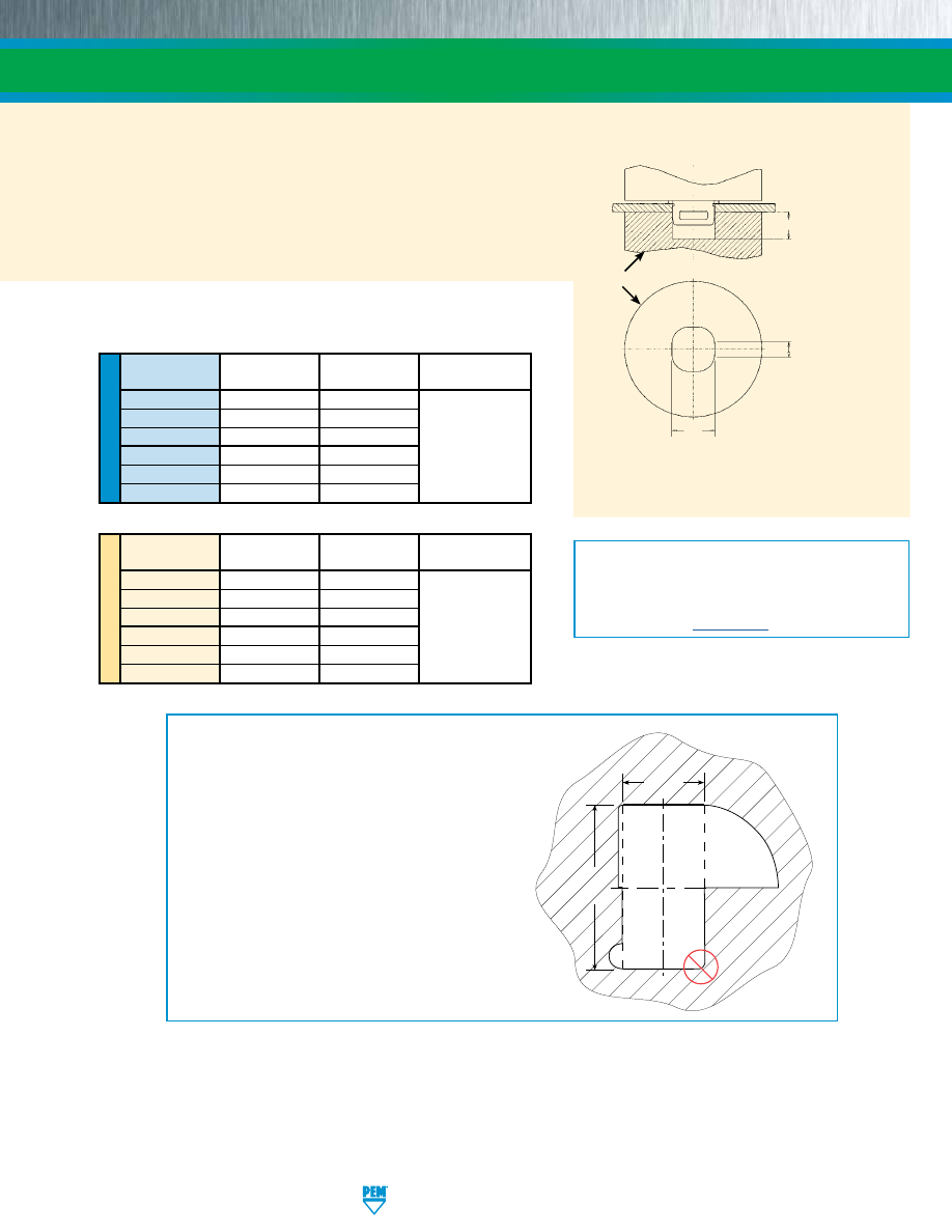
INSTALLATION
1.
Punch a properly sized rectangular mounting hole in the sheet. Do
not perform any secondary operations such as deburring.
2.
Place the fastener through the mounting hole (preferably the punch
side) and into the anvil.
3.
With the installation punch and anvil surfaces parallel, apply a
squeezing force until the bottom of the fastener becomes flush with
the sheet.
SELF-CLINCHING TY-D® CABLE TIE-MOUNTS AND HOOKS
TD-5
PennEngineering • www.pemnet.com
PEMSERTER® Installation Tooling
NOTE:
The punch must be large enough to cover the
entire base of the fastener to ensure proper installation.
W
ANVIL
PUNCH
G* +.010”/
+0.25mm Min.
L* +.005”/
+0.13mm Min.
flat length all
sides
* For “G” and “L”,
see pages 3 & 4.
INSTALLATION NOTES
•
For best results we recommend using a PEMSERTER® press
for installation of PEM self-clinching fasteners. Please check
our website for more information.
•
Visit the Animation Library on our website to view the
installation process
for this product
.
ME
TR
IC
U
NIF
IE
D
Part
W
Anvil Part
Punch Part
Number
±.001
Number
Number
TD-40-4 .251 8006136
TD-60-6
.313
8006137
TD-175-12 .501 8006138
8003076
TDO-40-8
.379
8006865
TDO-50-8
.442
8006864
TDO-120-8
.566
8006863
Part
W
Anvil Part
Punch Part
Number
±0.03
Number
Number
TD-40-4 6.36 8006136
TD-60-6
7.95
8006137
TD-175-12 12.73 8006138
8003076
TDO-40-8
9.63
8006865
TDO-50-8
11.23
8006864
TDO-120-8
14.38
8006863
All dimensions are in inches.
All dimensions are in millimeters.
The mounting hole is defined by two dimensions. The
two thick lines shown must be straight for the entire
length defined by “Side 2” and must be separated
by the distance shown as “Side 1” (Side 1 and Side
2 are the two dimensions given for the mounting
hole on pages 3 and 4). The illustration shows three
examples (#1, #2, and #3) of how it can be achieved.
Example #4 in the lower right side will not work.
MOUNTING HOLE EXAMPLES
Mounting
Hole
Side 2
Side 1
Hole
Example
#1
Hole
Example
#2
Hole
Example
#3
Hole
Example
#4
pem-html.html
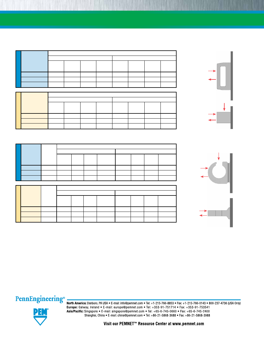
TD-6
SELF-CLINCHING TY-D® CABLE TIE-MOUNTS AND HOOKS
ME
TR
IC
U
NIF
IE
D
ME
TR
IC
U
NIF
IE
D
Test Sheet Material
Cold-rolled Steel
5052-H34 Aluminum
Part Number
Cable Tie
Installation Pushout Pull Thru Hanging Load Installation Pushout
Pull Thru Hanging Load
Screw
(lbs.)
(lbs.)
(lbs.)
(lbs.)
(lbs.)
(lbs.)
(lbs.)
(lbs.)
Size
TDO-40-8 #8 3000 105 70 145 2000 105 70 130
TDO-50-8
#10
3000
150
90
145
2000
130
90
130
TDO-120-8 1/4 3000 200 110 145 2000 145 110 130
Test Sheet Material
Cold-rolled Steel
5052-H34 Aluminum
Part Number
Cable Tie
Installation Pushout Pull Thru Hanging Load
Installation Pushout
Pull Thru Hanging Load
Screw
(kN)
(N)
(N)
(N)
(kN)
(N)
(N)
(N)
Size
TDO-40-8 M4 13.4 465 310 645
8.9 465 310 575
TDO-50-8
M5
13.4
665
400
645
8.9
575
400
575
TDO-120-8 M6 13.4 890 490 645
8.9 645 490 575
(1) Published installation forces are for general reference. Actual set-up and confirmation of complete
installation should be made by observing proper seating of fastener as described in the installation
steps. Other performance values reported are averages when all proper installation parameters
and procedures are followed. Variations in mounting hole size, sheet material, and installation
procedure may affect performance. Performance testing this product in your application is
recommended. We will be happy to provide technical assistance and/or samples for this purpose.
Test Sheet Material
Cold-rolled Steel
5052-H34 Aluminum
Part Number
Installation
Pushout
Pull Thru
Side Load
Installation
Pushout
Pull Thru
Side Load
(kN)
(N)
(N)
(N)
(kN)
(N)
(N)
(N)
TD-40-4
8 780 445 400 4.5 400 445 400
TD-60-6
11
1160
712 445 6.7
620
712 445
TD-175-12
17.7 1560 780 620 13.3 1040 780 620
Test Sheet Material
Cold-rolled Steel
5052-H34 Aluminum
Part Number
Installation
Pushout
Pull Thru
Side Load
Installation
Pushout
Pull Thru
Side Load
(lbs.)
(lbs.)
(lbs.)
(lbs.)
(lbs.)
(lbs.)
(lbs.)
(lbs.)
TD-40-4 1800 175 100 90 1000 90 100 90
TD-60-6
2500 260
160 100 1500 140
160 100
TD-175-12 4000 350 175 140 3000 235 175 140
PERFORMANCE DATA
(1)
Pull Thru
Pushout
Side Load
Pull Thru
Pushout
Hanging Load
Pull Thru
Pushout
Pull Thru
Pushout
Technical support e-mail: techsupport@pemnet.com
All PEM® products meet our stringent quality standards. If you require additional industry or other specific quality certifications, special procedures and/or part
numbers are required. Please contact your local sales office or representative for further information.
Regulatory compliance information is available in Technical Support section of our website. Specifications subject to change without notice. See our website for the
most current version of this bulletin.
© 2017 PennEngineering.
TD™ CABLE TIE-MOUNTS
TDO™ CABLE TIE HOOKS
pem-html.html
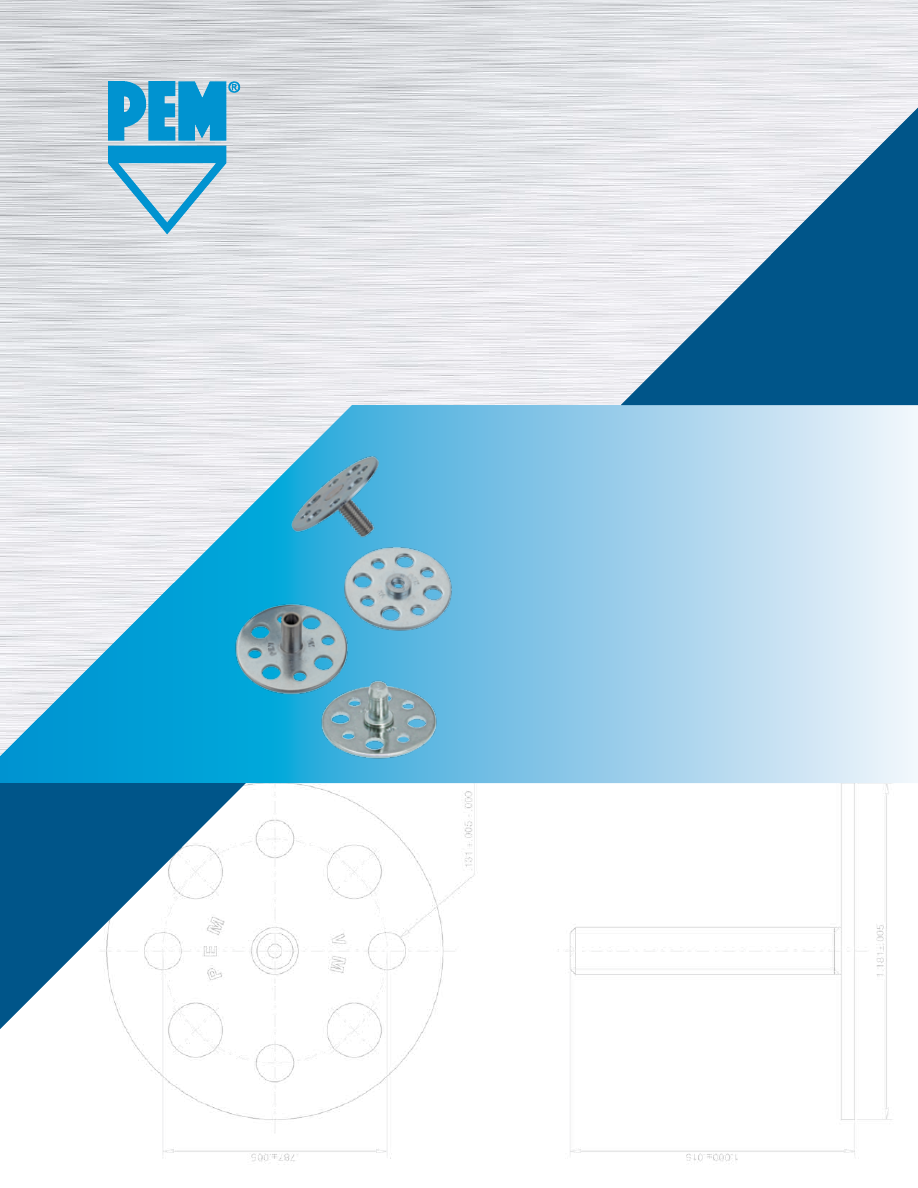
VM
™
PEM® VARIMOUNT®
BONDING FASTENERS
PEM® VariMount® bonding fasteners
are assemblies comprised of standard
PEM® fasteners mounted permanently
into base plates.
Bulletin VM-917
pem-html.html
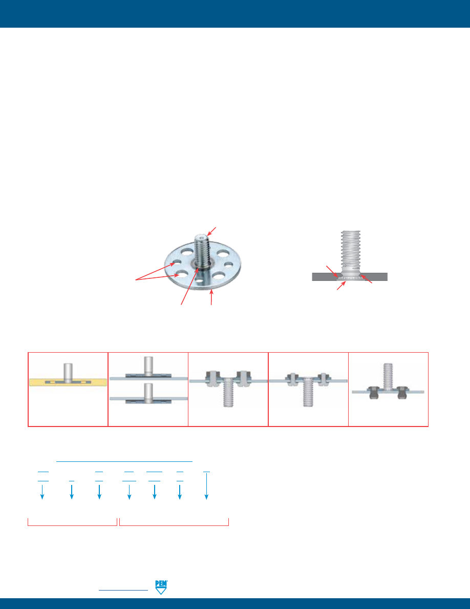
The PEM® VariMount® fastening system is an assembly comprised of a standard PEM® nuts, studs or standoffs mounted
permanently into a base plate. The assembly can then be fastened or bonded to assorted panel types in a variety of ways:
Mounting Methods:
Mounts on or in:
•
Mold-in
•
Self-clinching fasteners
•
Composites
•
Laminate within composite layers
•
Blind threaded rivets
•
Plastics
•
Surface bonding
•
Hollow wall anchors
•
Metal
•
Rivets
•
Spot welding
•
Wall board
•
Loose hardware (nuts, bolts, screws)
•
Any rigid material or panel
VariMount® assemblies are available with either steel or stainless steel base plates depending on the fastener that is
selected. The VariMount® base plate’s radial holes provide various mounting options.
Base plates can also be purchased separately. See page 5 for dimensional data and part numbers.
(1) “Blank” equals steel base plate and “C” equals stainless steel base plate.
(2) See page 5 for complete dimensional information.
(3) Required on steel assemblies.
TYPICAL MOUNTING METHODS
ASSEMBLY PART NUMBER DESIGNATION
VM 30
FH – 0420 – 16
ZI
VM
C
30
FHP – 032 – 16
Fastener
Thread
Code
Fastener
Type
Fastener
Length
Code
Base
Plate
Diameter
(2)
Fastener
Finish Code
(3)
(if applicable)
VariMount
Fastener
Style
Base plate prefix
PEM® fastener part number
Base Plate
Material
Code
(1)
A VariMount® assembly part number includes a base plate
prefix paired with a standard PEM® fastener part number.
Molded-in or laminate
within composite layers
Bonded using adhesives.
Top or bottom mount
Loose hardware
Self-clinching hardware
Rivets
VARIMOUNT® ASSEMBLY USING SELF-CLINCHING TECHNOLOGY
PEM® self-clinching flush-
head stud permanently
installed into baseplate.
Radial holes allow:
•
Better attachment with adhesives.
•
Encapsulating into plastic.
•
Attachment with standard sized rivets.
•
Attachment with standard sized clinch fasteners.
No head or shoulder protrusion.
30 mm baseplate provides
generous footprint.
Flush mounted.
Ribs on fastener provides
torque resistance.
Host metal of base plate
flows into undercut of
fastener “clinching” it
permanently in place.
PEM® VARIMOUNT® BONDING FASTENERS
VM-2
PennEngineering •
www.pemnet.com
© 2017 PennEngineering.
pem-html.html
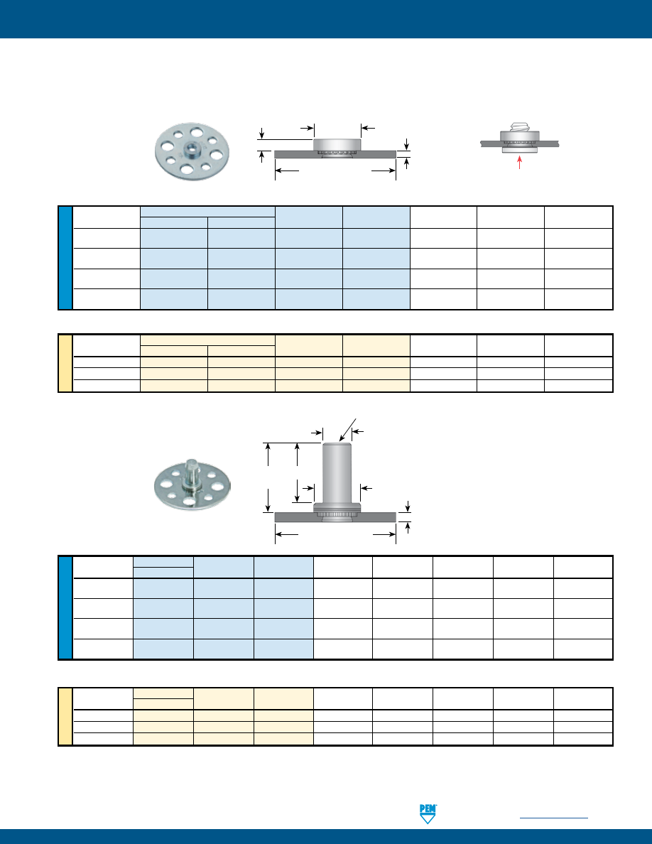
The charts below show PEM® fastener types/sizes that are offered as standard VariMount® assemblies.
U
NIF
IE
D
Thread Type and Material
Thread
Shank
BPT
E
T
Size
Steel
Stainless Steel
Code
Code
±.004
±.010
±.010
.112-40
VM30S- VMC30SP- 440
1
.048
.250
.070
(#4-40)
.138-32
VM30S- VMC30SP- 632
1
.048
.280
.070
(#6-32)
.164-32
VM30S- VMC30SP- 832
1
.048
.310
.090
(#8-32)
.190-32
VM30SS- VMC30SP- 032
2
.063
.340
.090
(#10-32)
All dimensions are in inches.
ME
TR
IC
Thread Size Type and Material
Thread
Shank
BPT
E
T
x Pitch
Steel
Stainless Steel
Code
Code
±0.1
±0.25
±0.25
M3 x 0.5
VM30S-
VMC30SP-
M3
1
1.2
6.35
1.5
M4 x 0.7
VM30S-
VMC30SP-
M4
1
1.2
7.87
2
M5 x 0.8
VM30SS-
VMC30SP-
M5
2
1.6
8.64
2
All dimensions are in millimeters.
U
NIF
IE
D
Thread
Type and Material Thread
Shank
BPT
B
E
L
T
Size
Steel
Code
Code
±.004
Max.
±.010
Max.
±.010
.112-40
VM30B- 440 1 .048 .150 .250 .335 .380
(#4-40)
.138-32
VM30B- 632 1 .048 .169 .280 .335 .380
(#6-32)
.164-32
VM30B- 832 1 .048 .204 .310 .385 .440
(#8-32)
.190-32
VM30B- 032 2 .063 .235 .340 .385 .440
(#10-32)
All dimensions are in inches.
STANDARD NUTS
BLIND NUTS
All dimensions are in millimeters.
1.181”
±.005” /
30 mm
±0.13 mm
T
E
BPT
BPT
1.181”
±.005” /
30 mm
±0.13 mm
B
L
Closed End
T
E
Install screw from this side
ME
TR
IC
Thread Size
Type and Material Thread
Shank
BPT
B
E
L
T
x Pitch
Steel
Code
Code
±0.1
Max.
±0.25
Max.
±0.25
M3 x 0.5
VM30B-
M3
1
1.2
3.84
6.35
8.5
9.6
M4 x 0.7
VM30B-
M4
1
1.2
5.2
7.95
9.8
11.2
M5 x 0.8
VM30B-
M5
2
1.6
6.02
8.75
9.8
11.2
PEM® VARIMOUNT® BONDING FASTENERS
PennEngineering •
www.pemnet.com
VM-3
pem-html.html
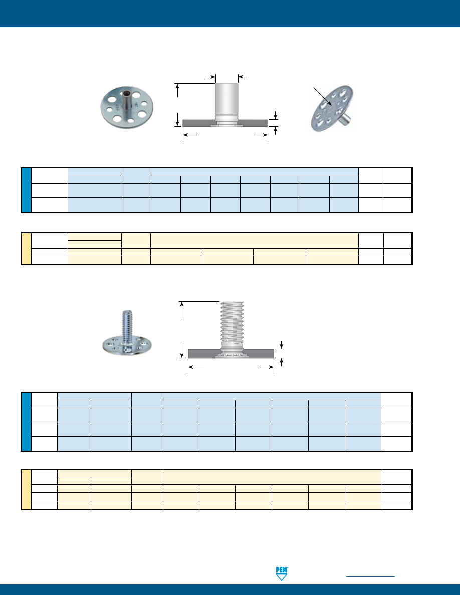
L
1.181”
±.005”
30 mm
±0.13 mm
BPT
The charts below show PEM® fastener types/sizes that are offered as standard VariMount® assemblies.
All dimensions are in inches.
STANDOFFS
U
NIF
IE
D
Thread
Type and Material
Thread
Length Code “L” +.002 –.005 (Length code in 32nds of an inch)
BPT
C
Size
Steel
Code
.375
.437
.500
.562
.625
.687
.750
±.004
+.000 –.005
.112-40
VM30BSO-
440 12 14
16
18 20 22 24 .048 .165
(#4-40)
.138-32
VM30BSO-
632 12 14
16
18 20 22 24 .048 .212
(#6-32)
All dimensions are in inches.
ME
TR
IC
Thread Size
Type and Material
Thread
Length Code “L” +0.05 –0.13
BPT
C
x Pitch
Steel
Code
(Length code in millimeters)
±0.1
–0.13
M3 x 0.5
VM30BSO-
M3
12
14
16
18
1.2
4.2
M3.5 x 0.6
VM30BSO-
M3.5
12
14
16
18
1.2
5.39
STUDS
All dimensions are in inches.
U
NIF
IE
D
Thread Type and Material
Thread
Length Code “L” ±.015 (Length code in 16ths of an inch)
BPT
Size
Steel
Stainless Steel
Code
.500
.625
.750
.875
1.00
1.25
±.004
.164-32
VM30FH- VMC30FHP- 832
8
10
12
14
16
20
.048
(#8-32)
.190-32
VM30FH- VMC30FHP- 032
8
10
12
14
16
20
.048
(#10-32)
.250-20
VM30FH- — 0420 8 10
12 14 16 20 .067
(1/4-20)
All dimensions are in inches.
ME
TR
IC
Thread Size Type and Material
Thread
Length Code “L” ±0.4
BPT
x Pitch
Steel
Stainless Steel
Code
(Length code in millimeters)
±0.1
M4 x 0.7
VM30FH-
VMC30FHP-
M4
10
12
15
18
20
25
1.2
M5 x 0.8
VM30FH-
VMC30FHP-
M5
10
12
15
18
20
25
1.2
M6 x 1
VM30FH-
—
M6
10
12
15
18
20
25
1.7
1.181”
±.005” /
30 mm
±0.13 mm
C
L
BPT
PEM® VARIMOUNT® BONDING FASTENERS
PennEngineering •
www.pemnet.com
VM-4
Closed end
pem-html.html
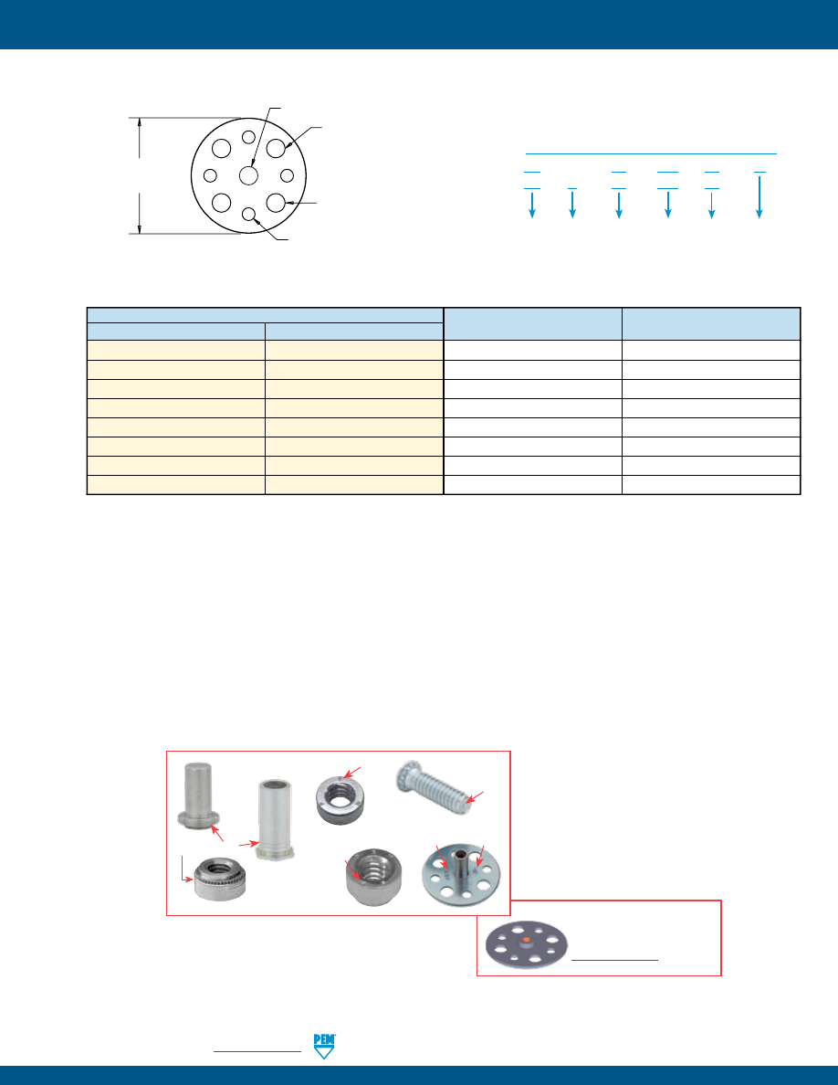
Drawings and models for
parts listed on pages 3, 4 & 5
are available at
www.pemnet.com
BASE PLATE PART NUMBER, DIMENSIONS AND MATERIAL GUIDE
BASE PLATE PART NUMBER DESIGNATION
BP 1.2 – 422 – 30
ZI
BP
C
1.2 – 422 – 30
Mounting
Hole “X”
Code
Plate
Thickness
Code
Base
Plate
Outside
Dia. Code
Plate
Material
Code
(3)
Finish
Code
(for steel)
Type
(1) Accepts standard M3.5 / #6-32 self-clinching nuts. Also flush-head studs #10-24 / #10-32 sizes. May also accept 4.8 mm / 3/16” rivet.
(2) Standard hole size for 3.2 mm / 1/8” rivet.
(3) “Blank” equals steel base plate and “C” equals stainless steel base plate.
(4) Use this part number if ordering base plate separately. Minimum quantities may apply.
(5) Base plate is carbon steel, zinc plated 5µm, colorless.
(6) Base plate is 300 series stainless steel, passivated and/or tested per ASTM A380.
Center Hole X
(4) Radial Holes
(1)
4.8 mm
+0.08 mm
.189”
+.003” -.000”
Centers of 8 radial holes equally spaced
on 20 mm
±0.13 mm
/ .787”
±.005”
nominal
diameter circle
30 mm
±0.13 mm /
1.181”
±.005”
(4) Radial Holes
(2)
3.33 mm
+0.13 mm
.131”
+.005” -.000”
Shown actual size.
NOTE ABOUT PERFORMANCE
General performance of PEM® fasteners in thin metal panels can be found in their respective PEM® Bulletins. Performance of the assembly (fastener and
base plate) mounted to your specific material, in your application will have to be determined by testing. We recommend that you perform testing to be
sure it is ideally suited to your application. We will be happy to provide technical assistance and/or samples to you for this purpose.
Base Plate Part Number
(4)
Thickness
Center Hole X Diameter
Steel
(5)
Stainless Steel
(6)
±0.1 mm / ±.004”
+0.08 mm / +.003” -.000”
BP1.2-422-30ZI
BPC1.2-422-30
1.2 mm / .048”
4.22 mm / .166”
BP1.2-480-30ZI
BPC1.2-480-30
1.2 mm / .048”
4.8 mm / .189”
BP1.2-541-30ZI
BPC1.2-541-30
1.2 mm / .048”
5.41 mm / .213”
BP1.6-635-30ZI
BPC1.6-635-30
1.6 mm / .063”
6.35 mm / .250”
BP1.2-400-30ZI
BPC1.2-400-30
1.2 mm / .048”
4 mm / .1575”
BP1.2-500-30ZI
BPC1.2-500-30
1.2 mm / .048”
5 mm / .1969”
BP1.6-600-30ZI
BPC1.6-600-30
1.6 mm / .063”
6 mm / .2362”
BP1.7-600-30ZI
BPC1.7-600-30
1.7 mm / .067”
6 mm / .2362”
Look for the trademarks to identify genuine PEM® fasteners.
Dimple
“PEM” Stamp
Two Grooves
“PEM VM” Stamp
on both sides
“PEM SP”
Stamp
VM-5
PennEngineering •
www.pemnet.com
PEM® VARIMOUNT® BONDING FASTENERS
pem-html.html
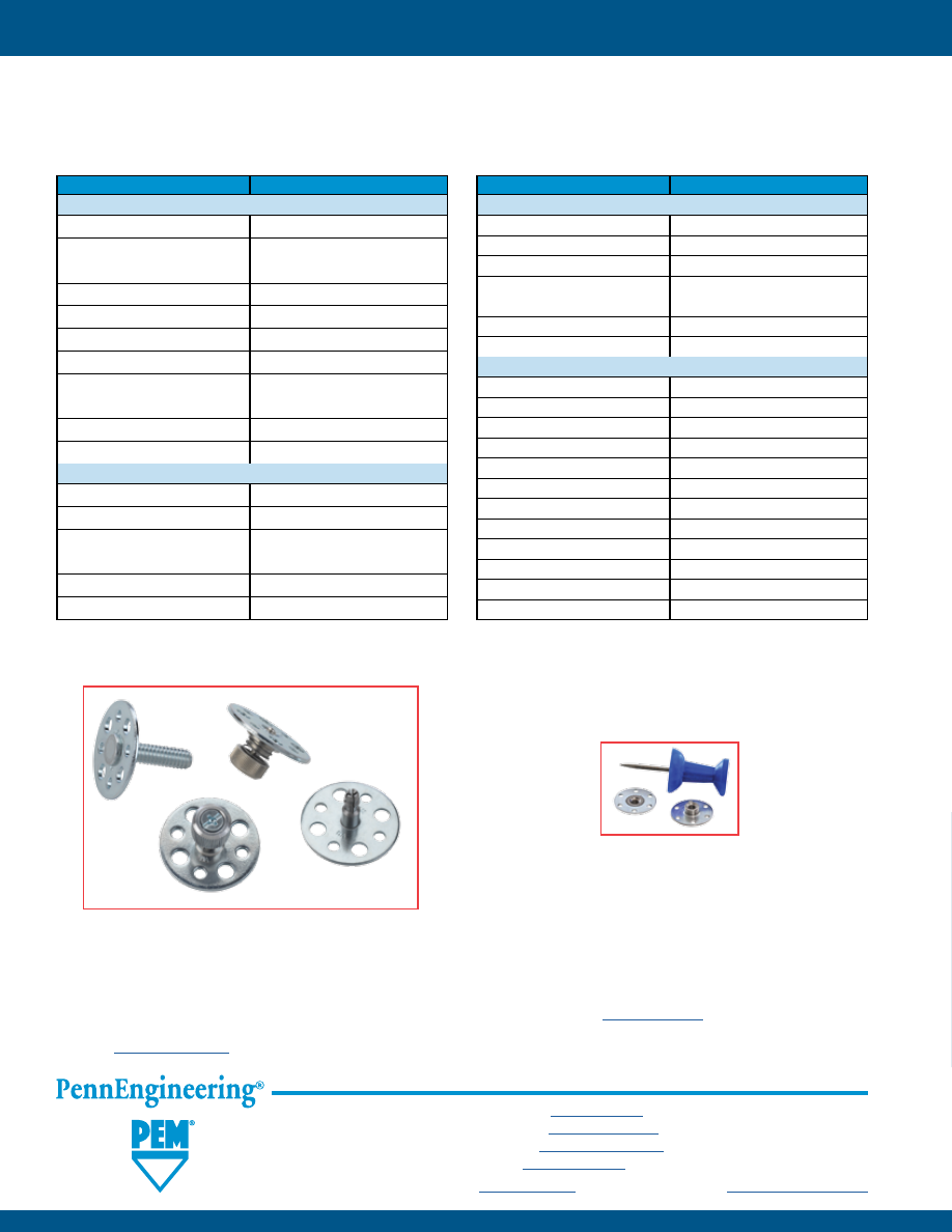
All PEM® products meet our stringent quality standards. If you require additional industry or other specific
quality certifications
, special procedures and/or part
numbers are required. Please contact your local sales office or representative for further information.
Regulatory
compliance information
is available in Technical Support section of our website. Specifications subject to change without notice. See our website for the
most current version of this bulletin.
North America:
Danboro, Pennsylvania USA
•
E-mail:
info@pemnet.com
•
Tel: +1-215-766-8853
•
800-237-4736 (USA)
Europe:
Galway, Ireland
•
E-mail:
europe@pemnet.com
•
Tel: +353-91-751714
Asia/Pacific:
Singapore
•
E-mail:
singapore@pemnet.com
•
Tel: +65-6-745-0660
Shanghai, China
•
E-mail:
china@pemnet.com
•
Tel: +86-21-5868-3688
Visit our PEMNET™ Resource Center at
www.pemnet.com
•
Technical support e-mail:
techsupport@pemnet.com
VM-6
OTHER PEM® FASTENER TYPES AND SIZES AVAILABLE
*
While we have listed the standard offering of assemblies on the charts (pages 3 and 4), other PEM® fasteners can be
provided pre-installed into one of the base plates listed on page 5. The charts below give a review of these fastener
types. To choose an assembly using one of these fasteners, simply create a part number as described on page 2.
PEM® Fastener Types
Standard Size Codes
Self-clinching Nuts
BS
440 / 632 / 832 / 032 / M3 / M4 / M5
CLS
256 / 348 / 440 / 632 / 832 /
M2 / M2.5 / M3 / M3.5 / M4
CLSS
024 / 032 / M5
LK, LKS
440 / M3
PL, PLC
M3
S
256 / 348 / M2 / M2.5 / M3.5
SL
440 / 632 / 832 / 032 /
M3 / M3.5 / M4 / M5
SP
256/ 024
SS
024
Self-clinching Studs
FH
024 / Non-threaded
FH4
832 / 032 / 0420 / M4 / M5 / M6
FHS
832 / 024 / 032 / 0420
M4 / M5 / M6 / Non-threaded
HFE
032 / 0420 / M5 / M6
HFH, HFHS
0420 / M6
PEM® Fastener Types
Standard Size Codes
Self-clinching Standoffs
BSO, BSOS,
BSO4
440 / 632 / 6440 / M3 / 3.5M3 / M3.5
DSO, DSOS
440 / M3
SO,
SO4
6440 / 3.5M3 / M3.5 / Non-threaded
SOS
440 / 632 / 6440 /
3.5M3 / M3 / M3.5 / Non-threaded
SOSG
6440 / 3.5M3
SSC, SSS
156 / 4MM
Panel Fasteners
N10
440 / 632 / 832 / M3
PF11, PF12, PF11M, PF12M
632
PF11MF, PF12MF
440 / M3
PF11MW, PF12MW
440 / M3
PF11PM
632
PF30
832
PF31, PF32
832 / M4
PF50, PF51, PF52, PF60, PF61, PF62
832 / M4
PF7M
632
PF7MF
440 / M3
SCB, SCBJ
M4
SCBR
832 / M4
* Other fasteners, base plate configurations and assemblies are available on special order. For questions, please contact our global technical support
team using the contact information listed at the bottom of this page. Appropriate minimum quantities may apply.
Types shown in bold italics can be installed into stainless steel base plates. Other types are not recommended for installation into stainless
steel base plates.
PEM® VARIMOUNT® BONDING FASTENERS
Special
Configurations
Available
Micro Sized Options Available
pem-html.html
WN
™
SELF-LOCATING
PROJECTION WELD NUTS
PEM® brand self-locating weld nuts
feature engineered projections, round
head design and a self-locating shank
Bulletin WN-717
pem-html.html
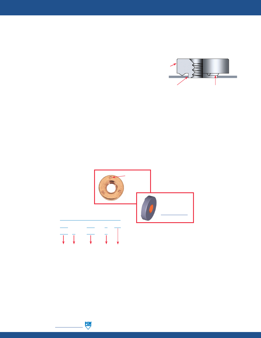
WN-2
PennEngineering •
www.pemnet.com
PEM® brand WN™/WNS™ weld nuts are designed to be welded onto another metal surface into properly sized holes. The
PEM® weld nut design helps overcome many problems associated with other welded nuts:
▶
Engineered projections
–
Prevent burnout-outs in thin sheets
–
Help keep the nut from warping while welding in high current
▶
Round head design
–
Eliminates tedious time-consuming indexing
–
Speeds production using standard equipment
–
Compact design fits on narrow flanges
▶
Self-locating shank
–
Eliminates the need for complex electrodes with pilots
–
Properly positions weld nuts
–
Protects threads from weld spatter
A variety of welding equipment is suitable for installation of PEM® weld nuts. Best results have been obtained with a 50KVA
press-type, spot-welding machine whose upper welding head moves vertically in a straight line with the lower electrode.
Flat-faced electrodes with tip diameters .125” / 3.2 mm larger than the “E” dimension of the PEM® weld nut should be used.
PEM® weld nuts are available in steel (WN™) or stainless steel (WNS™). Stainless steel nuts offer the added advantage of
corrosion resistance.
WN S – 632 – 0
Type
Finish
PART NUMBER DESIGNATION
Material
Code
Thread
Size Code
Shank
Code
WN – 632 – 0 CU
SELF-LOCATING PROJECTION WELD NUTS
© 2017 PennEngineering.
Round head
Self-locating shank
Engineered projections
“PEM” Stamp
(Registered
Trademark)
Fastener drawings
and models are
available at
www.pemnet.com
pem-html.html
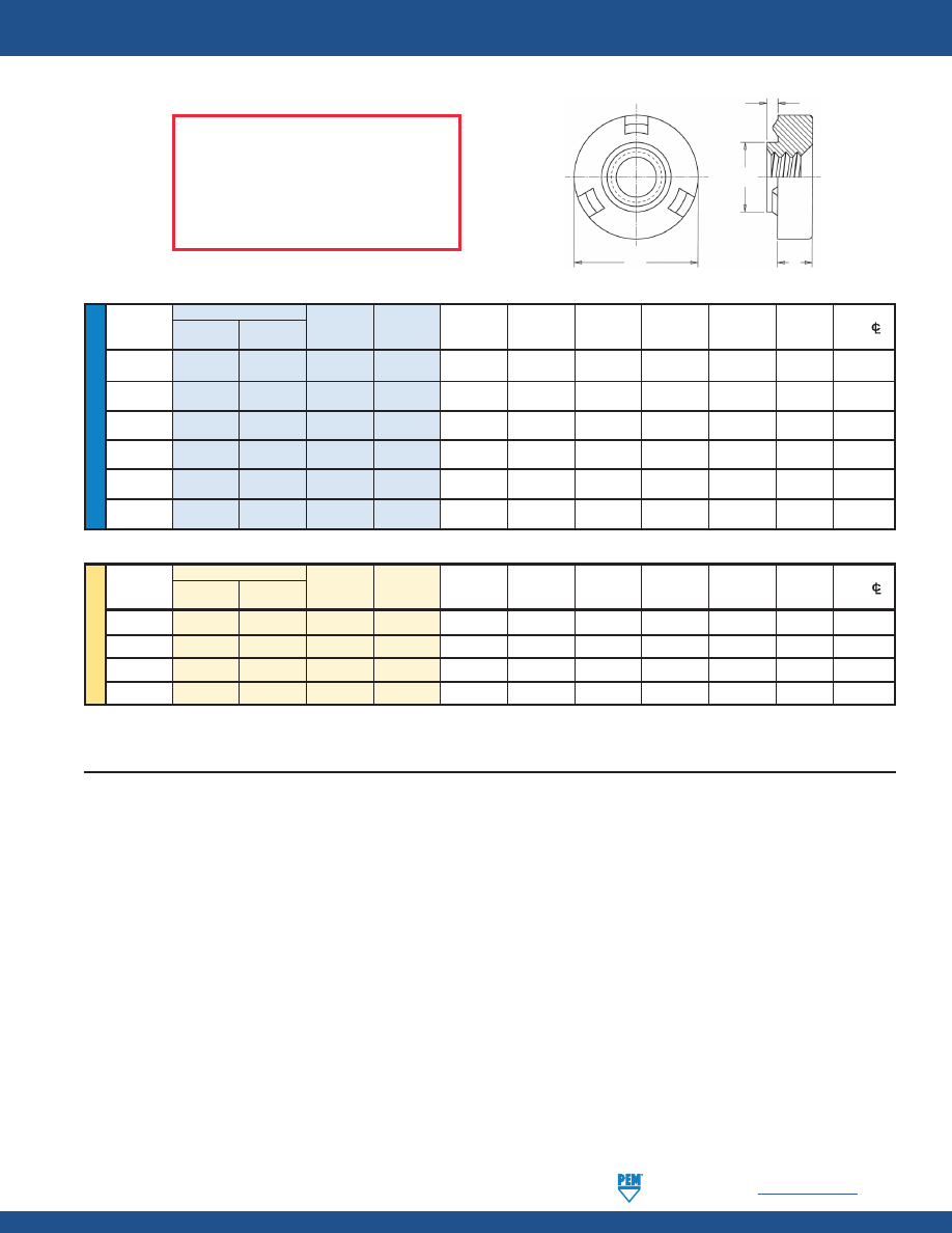
PennEngineering •
www.pemnet.com
WN-3
SELF-LOCATING PROJECTION WELD NUTS
ME
TR
IC
U
NIF
IE
D
INSTALLATION
1.
With a PEM® weld nut inserted in the properly sized hole (see above), bring the electrode force up sufficiently to clamp the projections of
the fastener firmly against the sheet without embedding any portion of the projections. Be sure the electrodes are centered, and that the
electrode faces are flat so that the force is applied evenly to all three projections.
2.
Set the current or heat regulator on the low side and adjust along with the weld time until a good weld is produced. For mild steel, which
has a medium electrical resistance, there is a wide range of adjustments possible. For austenitic stainless steel, which has a high electrical
resistance, the range is narrow at low heat.
3.
Adjust squeeze time so that there is adequate time for the electrodes to close and develop proper forces (suggested initial setting 35
cycles). The weld period should be established by starting with the settings suggested in the tables on page 4. As indicated above for
current adjustments, a wide range of time is possible with mild steel, but there is a limited range with stainless steel. If weld time starts too
soon, and proper welding is not achieved, the squeeze time should be lengthened. Also, the electrodes should be moved closer together
so that they require less travel time to close on the work. Longer squeeze times will have no effect on the quality of the weld. However,
they do affect productivity and decrease the number of weld nuts that can be installed per hour. Hold time is set long enough to permit
cooling and solidification of the weld before removing the electrodes. Start with 15 cycles and lengthen if necessary.
E
T
C
A
Type
Min.
Hole Size
Min. Dist.
Thread
Thread Shank A
Sheet
In Sheet
C E T
Hole
C/L
Size
Steel
Stainless Code Code (Shank)
Thickness
+.004 -.000
Max.
+.000 -.010
±.004
To Edge
Steel Max.
.112-40
WN WNS 440 0 .030 .030 .173 .172 .308 .065 .154
(#4-40)
.138-32
WN WNS 632 0 .030 .030 .193 .192 .341 .094 .171
(#6-32)
.164-32
WN WNS 832 0 .030 .030 .218 .217 .371 .108 .186
(#8-32)
.190-24
WN WNS 024 0 .030 .030 .250 .249 .440 .156 .220
(#10-24)
.190-32
WN WNS 032 0 .030 .030 .250 .249 .440 .156 .220
(#10-32)
.250-20
WN WNS 0420 0 .048 .048 .316 .315 .522 .186 .261
(1/4-20)
Type
Min.
Hole Size
Min. Dist.
Thread
Thread Shank
A
Sheet
In Sheet
C E T
Hole
C/L
Size x
Steel
Stainless Code Code (Shank)
Thickness +0.1 Max. –0.25 ±0.1
To Edge
Pitch Steel Max.
M3 x 0.5
WN
WNS
M3
0
0.77
0.77
4.39
4.36
7.82
1.49
3.91
M4 x 0.7
WN
WNS
M4
0
0.77
0.77
5.53
5.5
9.42
2.58
4.71
M5 x 0.8
WN
WNS
M5
0
0.77
0.77
6.35
6.32
11.17
3.78
5.59
M6 x 1
WN
WNS
M6
0
1.22
1.24
8.04
8.01
13.25
4.56
6.63
All dimensions are in inches.
All dimensions are in millimeters.
FASTENER MATERIAL:
WN – Carbon Steel
WNS – 300 Series Stainless Steel
FINISH:
WN – CU - Copper Flash
(1)
WNS – Passivated and/or tested per ASTM A380
THREADS:
Internal, ASME B1.1, 2B / ASME B1.13M, 6H
(1) Copper Flash plating prevents surface rust, facilitates automatic feeding, and requires no preparation before painting or finishing.
pem-html.html
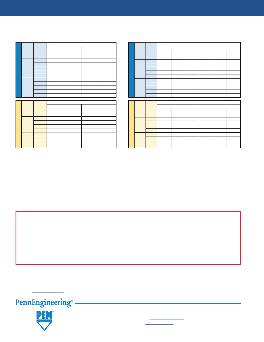
WN-4
SELF-LOCATING PROJECTION WELD NUTS
All PEM® products meet our stringent quality standards. If you require additional industry or other specific
quality certifications
, special procedures and/or part
numbers are required. Please contact your local sales office or representative for further information.
Regulatory
compliance information
is available in Technical Support section of our website. Specifications subject to change without notice. See our website for the
most current version of this bulletin.
ME
TR
IC
U
NIF
IE
D
ME
TR
IC
U
NIF
IE
D
PERFORMANCE DATA
(1)
GUIDES TO BETTER WELDING
Electrodes, weld nuts, and panels must be clean and free of grease, rust, and metal burrs. When welds appear satisfactory on installed nut, but pushout
values are low, one or more of the following may be the cause:
1)
Ram pressure too high.
2)
Current too low.
3)
Panel not clean.
4)
Weld nuts not centered under electrodes.
5)
Hold time not long enough to allow proper cooling.
6)
Pressure regulator on welding equipment drifts.
If installed threads are distorted, the following singly or in combination may be the cause:
1)
Weld time too long.
2)
Current too high.
3)
Ram pressure too high.
Should it be impossible to produce a proper weld because weld time starts before electrodes close on the work, shorten the gap between the electrodes
so that they take less time to move into position and/or lengthen the squeeze time.
Test Sheet Material
Type
Thread Cold-rolled Steel 302 Stainless Steel
Code
Electrode (A) Secondary
(B) Weld Electrode
(A) Secondary
(B) Weld
Ram Force
Current
Time (C)
Ram Force
Current
Time (C)
(N)
Amps ±500
Cycles/Sec.
(N)
Amps ±500
Cycles/Sec.
M3
2000-2220
17,000
6 / 0.10
N/A
N/A
N/A
M4
2000-2220
17,000
6 / 0.10
N/A
N/A
N/A
WN
M5
2220-2440
18,000
10 / 0.17
N/A
N/A
N/A
M6
2440-2670
20,000
10 / 0.17
N/A
N/A
N/A
M3
N/A
N/A
N/A
2000-2220
16,500
6 / 0.10
M4
N/A
N/A
N/A
2220-2440
16,500
6 / 0.10
WNS
M5
N/A
N/A
N/A
2440-2670
18,500
6 / 0.10
M6
N/A
N/A
N/A
2890-3110
20,000
6 / 0.10
N/A Not Applicable.
(1) Published installation forces are for general reference. Actual set-up and confirmation of complete installation should be made by observing proper
seating of fastener as described in the installation steps. Other performance values reported are averages when all proper installation parameters
and procedures are followed. Variations in mounting hole size, sheet material, and installation procedure may affect performance. Performance
testing this product in your application is recommended. We will be happy to provide technical assistance and/or samples for this purpose.
(A) Electrode Force is the force exerted by the electrodes on the fastener and sheet to clamp them together and ensure good electrical contact. Electrode force also
sets the weld nut down flush on the sheet as the projections melt during the welding period. Insufficient electrode force may result in flashing, spitting, burning,
spatter, and discoloration. On the other hand, excessive electrode force may flatten the fastener projections before proper welding temperature is reached or may
embed the projections of the cold fastener into the sheet. Excessive electrode force can also distort threads during the weld cycle.
(B) Secondary Current determines the heat applied to the PEM® weld nut and sheet. Heat is in direct proportion to weld time, resistances of the materials, and the
square of the current. Current should not be set so high as to cause flashing or spattering or excessive heat which will distort the threads. Low currents may produce
good looking welds but pushout and torque-out strengths will not be satisfactory.
(C) Timing Cycle for projection welding comprises four periods. 1) the squeeze time in which the electrodes move into position and develop the required force; 2) the
weld time when the current is applied; 3) the hold time while the weld congeals and cools; and (4) the off time for positioning the work for the next weld nut.
NOTE: The setting guides shown in the above charts are for reference only and may differ for your welding equipment.
Test Sheet Material
Type
Thread Cold-rolled Steel 302 Stainless Steel
Code
Electrode (A) Secondary (B) Weld Electrode
(A) Secondary
(B) Weld
Ram Force
Current
Time (C)
Ram Force
Current
Time (C)
(lbs.)
Amps ±500
Cycles/Sec.
(lbs.)
Amps ±500
Cycles/Sec.
440
450-500
17,000
6 / 0.10
N/A
N/A
N/A
632
450-500
17,000
6 / 0.10
N/A
N/A
N/A
WN
832
450-500
17,000
6 / 0.10
N/A
N/A
N/A
032
500-550
18,000
10 / 0.17
N/A
N/A
N/A
0420
550-600
20,000
10 / 0.17
N/A
N/A
N/A
440
N/A
N/A
N/A
450-500
16,500
6 / 0.10
632
N/A
N/A
N/A
450-500
16,500
6 / 0.10
WNS
832
N/A
N/A
N/A
500-550
16,500
6 / 0.10
032
N/A
N/A
N/A
550-600
18,500
6 / 0.10
0420
N/A
N/A
N/A
650-700
20,000
6 / 0.10
Test Sheet Material
Type Thread .060” Cold-rolled Steel .060” 302 Stainless Steel
Code
Pushout Torque-out Pushout Torque-out
(lbs.)
(in. lbs.)
(lbs.)
(in. lbs.)
440
500
13
N/A
N/A
632
640
22
N/A
N/A
WN
832
760
33
N/A
N/A
032
880
56
N/A
N/A
0420
1000
185
N/A
N/A
440
N/A
N/A
680
13
632
N/A
N/A
800
28
WNS
832
N/A
N/A
850
45
032
N/A
N/A
900
110
0420
N/A
N/A
1000
200
Test Sheet Material
Type
Thread 1.5 mm Cold-rolled Steel 1.5 mm 302 Stainless Steel
Code
Pushout Torque-out Pushout Torque-out
(N) (N•m) (N) (N•m)
M3
2220
1.4
N/A
N/A
M4
3380
3.7
N/A
N/A
WN
M5 3910
6.3
N/A
N/A
M6
4445
20.9
N/A
N/A
M3
N/A
N/A
3020
1.4
M4
N/A
N/A
3780
5
WNS
M5
N/A
N/A
4000
12.4
M6
N/A
N/A
4445
22.5
SETTING GUIDES FOR PEM® WELD NUTS IN
.030”/0.77 MM TO .063”/1.6 MM SHEETS
North America:
Danboro, Pennsylvania USA
•
E-mail:
info@pemnet.com
•
Tel: +1-215-766-8853
•
800-237-4736 (USA)
Europe:
Galway, Ireland
•
E-mail:
europe@pemnet.com
•
Tel: +353-91-751714
Asia/Pacific:
Singapore
•
E-mail:
singapore@pemnet.com
•
Tel: +65-6-745-0660
Shanghai, China
•
E-mail:
china@pemnet.com
•
Tel: +86-21-5868-3688
Visit our PEMNET™ Resource Center at
www.pemnet.com
•
Technical support e-mail:
techsupport@pemnet.com
pem-html.html
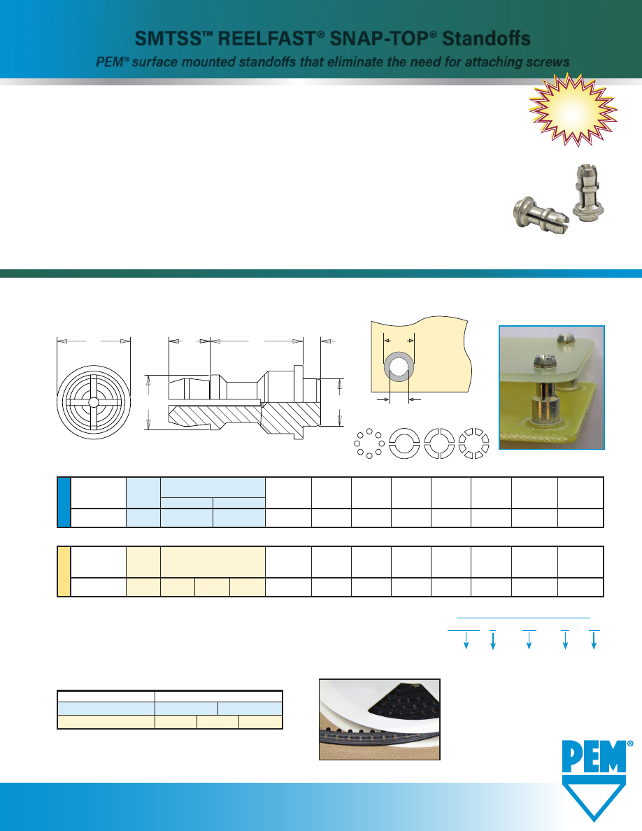
SMTSS™ REELFAST® SNAP-TOP® STANDOFFS
www.pemnet.com
•
PEM® SMTSS™ fasteners feature a spring action to hold a P.C. Board securely without
screw or threaded hardware.
•
Designed for on-only applications.
*
•
Mount on P.C. Boards in the same manner and at the same time as other surface mount
components prior to the automated reflow solder process.
•
Alleviates concerns about potential damage to P.C. Boards due to improper secondary installation
operations.
•
Fasteners provided on tape and reel compatible with existing SMT automated
installation equipment.
•
Benefits include reduced scrap, reduced handling and reduced risk of board damage.
* For removal applications, mounting hole can be increased to reduce removal force. Testing this product in your application is recommended.
SMTSS™ REELFAST® SNAP-TOP® Standoffs
PEM® surface mounted standoffs that eliminate the need for attaching screws
SMTSS-517
NEW!
Ø
H
Ø
D
Solder
Pad
Plated through hole
not required.
Stencil Masking Examples
NUMBER OF PARTS PER REEL
Packaged on 330 mm recyclable reels. Tape width is 24 mm.
Supplied with polyimide patch for vacuum pick up. Reels conform to EIA-481.
E
P
L
A
C
B
U
NIF
IE
D
Top
Board
Min.
ØH
Hole
ØD
Mounting Hole Type and
Sheet
A
C
E
B
P
Size in Sheet
Min.
Diameter Code
Material
.250 .375
Thickness
Max.
Max.
±.005
±.005
±.005
+.003 –.000
Solder Pad
156 SMTSSS 8
12
.060 .060 .161 .250 .188 .141
.166
.276
Length Code “L” ±.005
(Length Code in 32nds of an inch)
All dimensions are in inches.
ME
TR
IC
Top
Board
Min.
ØH
Hole
ØD
Mounting Hole Type and
Sheet
A
C
E
B
P
Size in Sheet
Min.
Diameter Code
Material
Thickness Max. Max. ±0.13 ±0.13 ±0.13 +0.08 Solder
Pad
4MM SMTSSS 6
8 10
1.53
1.53 4.09 6.35 4.8 3.58
4.22
7
Length Code “L” ±0.13
(Length Code in millimeters)
All dimensions are in millimeters.
Type, Material and Size Length Code / Number of Parts per Reel
SMTSSS-156
-8 / 280
-12 / 220
SMTSSS-4MM
-6 / 300
-8 / 250
-10 / 200
Fastener Material:
Carbon Steel
Finish:
Electro-plated tin ASTM B 545, Class A with Clear Preservative Coating, annealed
(1)(2)
(
1) See PEM Technical Support section of our web site for related plating standards and specifications.
(2) Optimal solderability life noted on packaging.
SMTSS S – 156 – 12 ET
PART NUMBER DESIGNATION
Panel 2 (Top)
Mounting Hole
Diameter Code
Length
Code
Finish
Type Material
pem-html.html
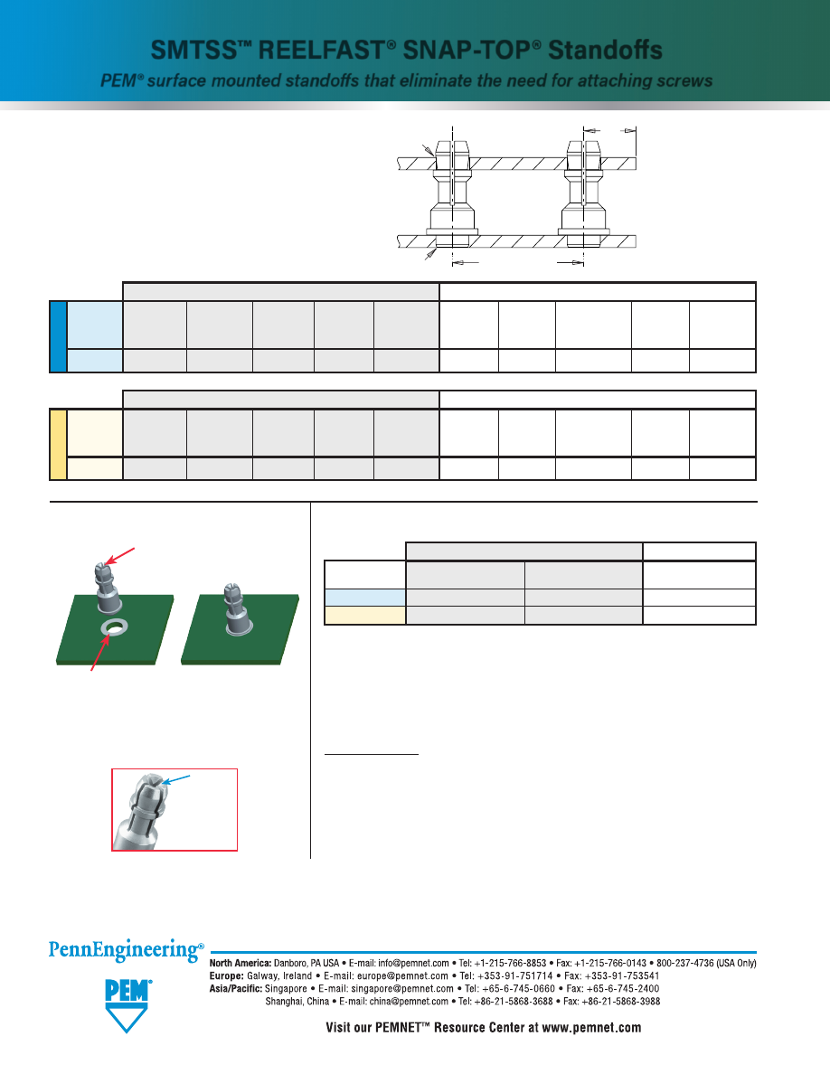
SMTSS-2
Technical support e-mail: techsupport@pemnet.com
All PEM® products meet our stringent quality standards. If you require additional industry or other specific quality certifications, special procedures and/or part
numbers are required. Please contact your local sales office or representative for further information.
Regulatory compliance information is available in Technical Support section of our website. Specifications subject to change without notice. See our website for the
most current version of this bulletin.
© 2017 PennEngineering.
SMTSS™ STANDOFF
APPLICATION DATA
INSTALLATION
PERFORMANCE DATA
(1)
U
NIF
IE
D
Bottom
Top
Edge
Hardness Mounting Panel Thickness
Location Hardness Mounting
Panel
Thickness
Distance
Type
Max.
Hole B
Material
Min.
Tolerance
Max.
Hole A
Material
Range
C Min.
+.003 -.000
+.003 -.000
SMTSS
No Limit
.166
P.C. Board
.060
±.005
No Limit
.156
P.C. Board or Metal
.040 - .070
.100
Panel 1
Panel 2
All dimensions are in inches.
Solder paste applied
to pad on PCB.
Solder fastener in place
using standard surface
mount techniques.
Polyimide patch applied here for
vacuum pick up.
Mounting Hole A
Mounting Hole B
Location Tolerance
Edge
C
PANEL 2 (TOP)
PANEL 1 (BOTTOM)
Dimple
(Registered
trademark)
Fastener drawings and models are available at
www.pemnet.com
ME
TR
IC
Bottom
Top
Edge
Hardness Mounting Panel Thickness
Location Hardness Mounting
Panel
Thickness
Distance
Type
Max.
Hole B
Material
Min.
Tolerance
Max.
Hole A
Material
Range
C Min.
+0.08
+0.08
SMTSS
No Limit
4.22
P.C. Board
1.53
±0.13
No Limit
4
P.C. Board or Metal
1 - 1.8
2.54
Panel 1
Panel 2
All dimensions are in millimeters.
SMTSS™ REELFAST® SNAP-TOP® Standoffs
PEM® surface mounted standoffs that eliminate the need for attaching screws
TESTING CONDITIONS
Oven
Quad ZCR convection oven
with 4 zones
High Temp
473˚F / 245˚C
Board Finish
62% Sn, 38% Pb
Board
.062" / 1.58 mm thick, Single Layer FR-4
Screen Printer
Ragin Manual Printer
(1) Further testing details can be found in our website’s literature section.
(2) With lead-free paste. Average values of 30 test points. The data presented here is for
general comparison purposes only. Actual performance is dependent upon application
variables. We will be happy to provide samples for you to install. If required, we can also
test your installed hardware and provide you with the performance data specific to your
application.
Vias
None
Spokes
2 Spoke Pattern
Paste
Alpha CVP-390 Sn96.5/3.0Ag/
0.5Cu (SAC305)
Stencil
.0067” / 0.17 mm thick
Type, Material
Test Sheet Material
Pushout (2)
Max. Snap-on Force
and Size
SMTSSS-156
.062" Single Layer FR-4
113 lbs.
20 lbs.
SMTSSS-4MM
1.58 mm Single Layer FR-4
500 N
89 N
Panel 1 (Bottom)
Panel 2 (Top)
pem-html.html
S-RT
™
FREE-RUNNING
LOCKNUTS
PEM® brand RT™ free-running locknuts
have a thread form that creates a lock
when clamp load is applied
Bulletin S-RT-1017
NEW!
pem-html.html
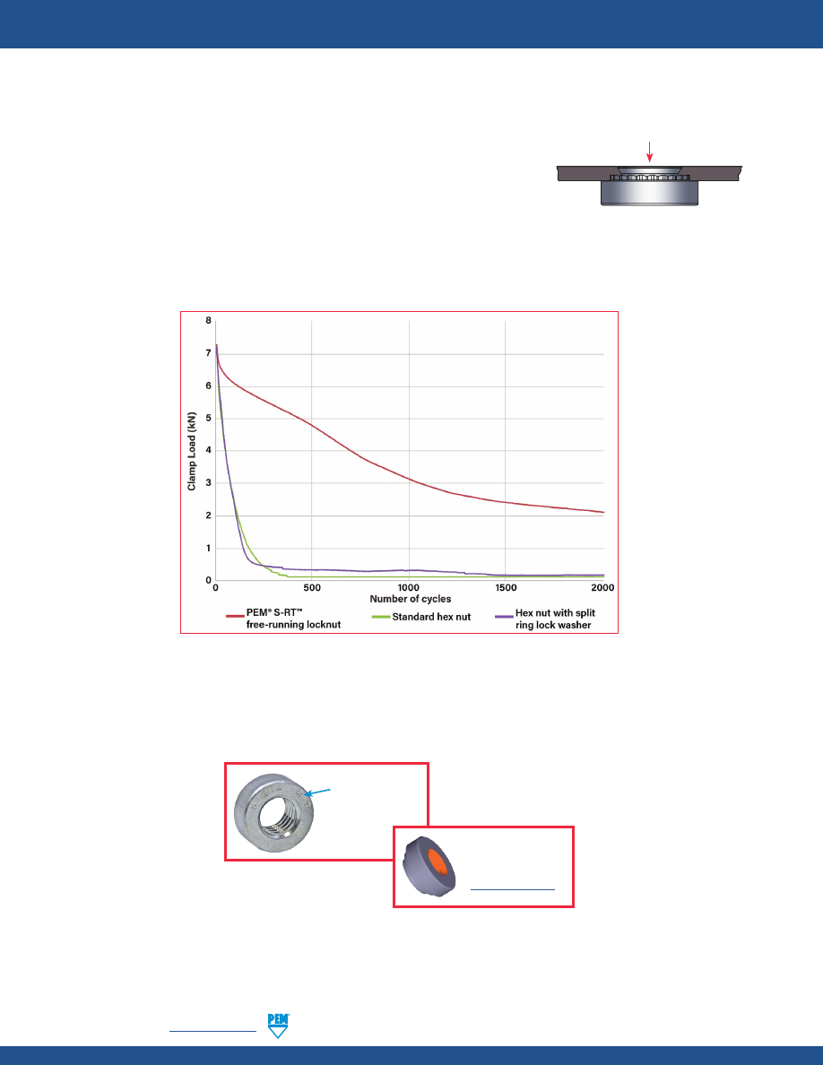
RT-2
PennEngineering •
www.pemnet.com
PEM® S-RT™ free-running locknuts are free-running until clamp load is induced. A modified thread angle on the loaded
flank provides the vibration resistant locking feature.
•
Screw turns freely until a clamp load is applied.
•
Resistant to vibrational loosening.
•
Back side of panel is flush or sub-flush for screw installation.
•
Locking feature reusability is not affected by number of on/off cycles.
•
Uses same mounting hole and installation tooling as standard S™ nut fasteners
found in PEM® Bulletin CL.
PEM® S-RT™ FREE-RUNNING LOCKNUTS
© 2017 PennEngineering.
The graph below represents the clamp load of the joint versus the amount of cycles during transverse vibration testing for
an S-RT™ free-running locknut, a standard hex nut and a hex nut with a split ring lock washer.
Screw enters here
“PEM RT” stamp
(Trademark)
Fastener drawings
and models are
available at
www.pemnet.com
Testing conditions:
Transverse vibration testing.
M6 thread size nuts, average of 30 pieces.
Clamp load applied using metric property class 10.9 screws.
Nuts tested until loss of clamp load or 2,000 cycles is reached.
pem-html.html
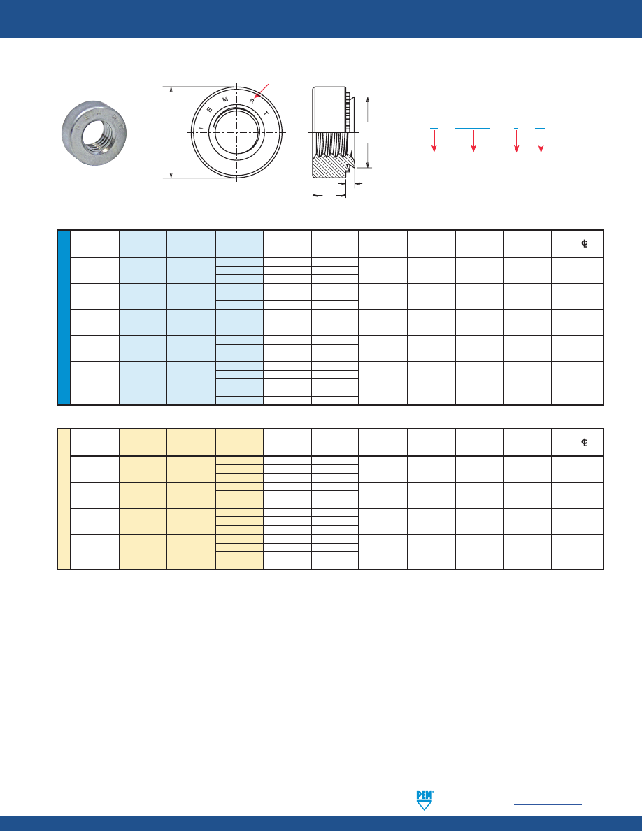
PennEngineering •
www.pemnet.com
RT-3
PEM® S-RT™ FREE-RUNNING LOCKNUTS
(1) For maximum performance, we recommend that you use the maximum shank length for your sheet thickness.
(2) See PEM
Technical Support
section of our website for related plating standards and specifications.
Type
Finish
PART NUMBER DESIGNATION
Thread
Code
Shank
Code
S - RT632 – 1 ZI
U
NIF
IE
D
A
Rec.
Hole Size
Min. Dist
Thread
Type
Thread
Shank
(Shank)
Min. Sheet
In Sheet
C
E
T
Hole
CL
Size
Code
Code
Max.
Thickness (1)
+.003 –.000
Max.
+.010
+.010
To Edge
.112-40 0 .030 .030
(#4-40)
S RT440 1 .038 .040 .166 .165 .250 .070 .19
2
.054
.056
.138-32 0 .030 .030
(#6-32)
S RT632 1 .038 .040 .1875 .187 .280 .070 .22
2
.054
.056
.164-32 0 .030 .030
(#8-32)
S RT832 1 .038 .040 .213 .212 .310 .090 .27
2
.054
.056
.190-32 0 .030 .030
(#10-32)
SS RT032 1 .038 .040 .250 .249 .340 .090 .28
2
.054
.056
.250-20 0 .045 .047
(1/4-20)
S RT0420 1 .054 .056 .344 .343 .440 .170 .34
2
.087
.090
.313-18
S RT0518 1 .054 .056 .413 .412 .500 .230 .38
(5/16-18)
2 .087 .090
All dimensions are in inches.
ME
TR
IC
Thread
A
Rec.
Hole Size
Min. Dist
Size x
Type
Thread
Shank
(Shank)
Min. Sheet
In Sheet
C
E
T
Hole
CL
Pitch
Code
Code
Max.
Thickness (1)
+0.08
Max.
+0.25
+0.25
To Edge
0
0.77
0.8
M3 x 0.5
S RTM3 1 0.97 1 4.22 4.2 6.35 1.5 4.8
2
1.38
1.4
0
0.77
0.8
M4 x 0.7
S
RTM4
1
0.97
1
5.41
5.38
7.87
2
6.9
2
1.38
1.4
0
0.77
0.8
M5 x 0.8
SS
RTM5
1
0.97
1
6.35
6.33
8.64
2
7.1
2
1.38
1.4
00
0.89
0.92
M6 x 1
S
RTM6 0 1.15 1.2 8.75 8.73 11.18 4.08 8.6
1
1.38
1.4
2
2.21
2.29
All dimensions are in millimeters
MATERIAL AND FINISH SPECIFICATIONS
THREADS:
Modified thread form on loaded flank. Will accept a maximum material 6g screw
FASTENER MATERIAL:
Hardened Carbon Steel
FINISH
(2)
:
Standard: ZI - Zinc plated, 5µm, colorless
Optional: ZC - Zinc plated, 5µm, yellow
FOR USE IN SHEET HARDNESS:
HRB 80 (Hardness Rockwell “B” scale) / HB 150 (Hardness Brinell) or less
E
C
T
A
Clinching profile may vary.
“PEM RT” Stamp (Trademark)
pem-html.html
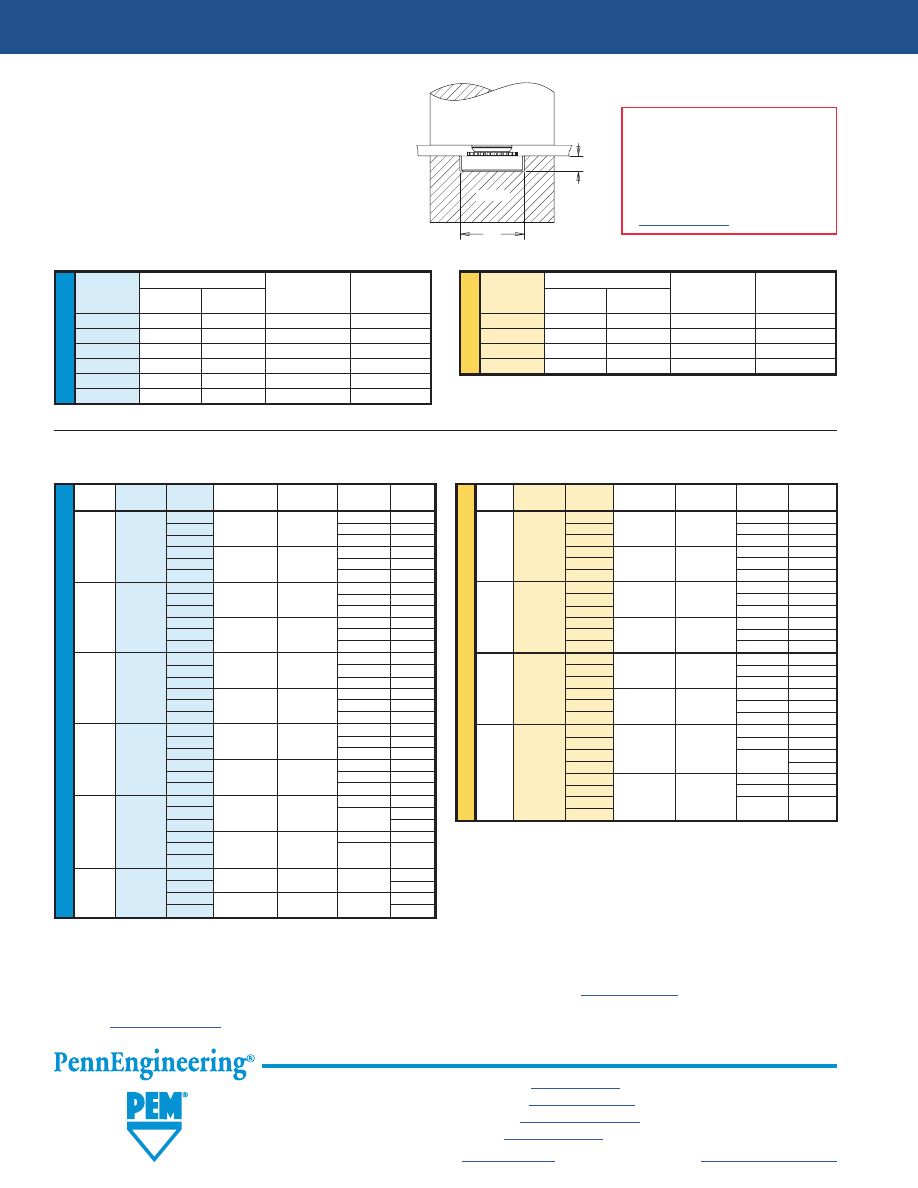
RT-4
All PEM® products meet our stringent quality standards. If you require additional industry or other specific
quality certifications
, special procedures and/or part
numbers are required. Please contact your local sales office or representative for further information.
Regulatory
compliance information
is available in Technical Support section of our website. Specifications subject to change without notice. See our website for the
most current version of this bulletin.
North America:
Danboro, Pennsylvania USA
•
E-mail:
info@pemnet.com
•
Tel: +1-215-766-8853
•
800-237-4736 (USA)
Europe:
Galway, Ireland
•
E-mail:
europe@pemnet.com
•
Tel: +353-91-751714
Asia/Pacific:
Singapore
•
E-mail:
singapore@pemnet.com
•
Tel: +65-6-745-0660
Shanghai, China
•
E-mail:
china@pemnet.com
•
Tel: +86-21-5868-3688
Visit our PEMNET™ Resource Center at
www.pemnet.com
•
Technical support e-mail:
techsupport@pemnet.com
PEM® S-RT™ FREE-RUNNING LOCKNUTS
INSTALLATION
1.
Prepare properly sized mounting hole in sheet. Do not
perform any secondary operations such as deburring.
2.
Place fastener into the anvil hole and place the mounting
hole (preferably the punch side) over the shank of the
fastener as shown in diagram.
3.
With installation punch and anvil surfaces parallel, apply
squeezing force until the head of the nut comes into
contact with the sheet material.
PUNCH
ANVIL
A
P
ME
TR
IC
U
NIF
IE
D
Anvil Dimensions (in.)
Thread
A P
Anvil Part
Punch Part
Code
±.002
±.005
Number
Number
RT440
.267
.045
975200034
975200048
RT632
.298
.045
975200035
975200048
RT832
.330
.070
975200036
975200048
RT032
.361
.070
975200037
975200048
RT0420
.454
.150
975200038
975200048
RT0518
.517
.200
975200039
975200048
Anvil Dimensions (mm)
Thread
A P
Anvil Part
Punch Part
Code
±0.05
±0.13
Number
Number
RTM3
6.78
1.14
975200034
975200048
RTM4
8.38
1.78
975200036
975200048
RTM5
9.17
1.78
975200037
975200048
RTM6 11.53 3.81 975200038
975200048
PEMSERTER®
Installation Tooling
INSTALLATION NOTES
•
For best results we recommend using
a PEMSERTER® press for installation
of PEM self-clinching fasteners. Please
check our website for more information.
•
Visit the Animation Library on our
website to view the installation process
for select products
.
PERFORMANCE DATA
(1)
U
NIF
IE
D
Type
Thread
Shank
Test Sheet
Installation
Pushout
Torque-out
Code
Code
Material
(lbs.)
(lbs.)
(in. lbs.)
0
5052-H34
63 8
1
Aluminum 1500-2000 90
10
S RT440 2
170 13
0
Cold-rolled 105 13
1
Steel 2500-3500 125 15
2
230
18
0
5052-H34
63 16
1
Aluminum 2500-3000 95
17
S RT632 2
190 22
0
Cold-rolled 110 16
1
Steel 3000-6000 130 20
2
275
28
0
5052-H34 68 21
1
Aluminum 2500-3000 105
23
S RT832 2
220 35
0
Cold-rolled
110 26
1
Steel 4000-6000 145 35
2
285
45
0
5052-H34
68 26
1
Aluminum 2500-3500 110
32
SS RT032 2
190 50
0
Cold-rolled
120 32
1
Steel 4000-9000 180 40
2
320
60
0
5052-H34 220 70
1
Aluminum 4000-7000 360 90
S RT0420 2
125
0
Cold-rolled
315 115
1
Steel 6000-8000 400 150
2
1
5052-H34 4000-7000 380 120
S RT0518 2 Aluminum
160
1
Cold-rolled 6000-8000 420 165
2
Steel
180
ME
TR
IC
Type
Thread
Shank
Test Sheet
Installation
Pushout
Torque-out
Code
Code
Material
(kN)
(N)
(N•m)
0
5052-H34
280 0.9
1
Aluminum 6.7-8.9 400 1.13
S RTM3 2
750 1.47
0
Cold-rolled
470 1.47
1
Steel 11.2-15.6 550 1.7
2
1010
2.03
0
5052-H34
300 2.37
1
Aluminum 11.2-13.4 470 2.6
S RTM4 2
970 4
0
Cold-rolled
490 2.95
1
Steel 18-27 645 4
2
1250 5.1
0
5052-H34 300 3
1
Aluminum 11.2-15.6 480 3.6
SS RTM5 2
845 5.7
0
Cold-rolled
530 3.6
1
Steel 18-38 800 4.5
2
1112
6.8
00
750
6.5
0
5052-H34
18-32 970 7.9
1
Aluminum
1580 10.2
S RTM6 2
14.1
00
900
10
0
Cold-rolled
27-36 1380 13
1
Steel
1760 17
2
(1) Published installation forces are for general reference. Actual set-up and
confirmation of complete installation should be made by observing proper
seating of fastener as described in the installation steps. Other performance
values reported are averages when all proper installation parameters and
procedures are followed. Variations in mounting hole size, sheet material,
and installation procedure may affect performance. Performance testing
this product in your application is recommended. We will be happy to
provide technical assistance and/or samples for this purpose.
pem-html.html
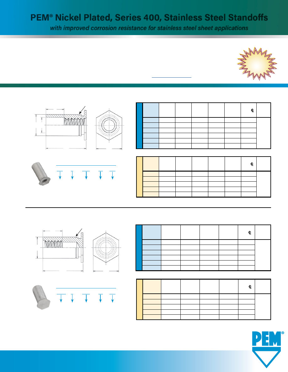
TYPE SO4™ THROUGH-HOLE THREADED STANDOFFS
www.pemnet.com
NEW!
U
NIF
IE
D
Min.
Hole Size
B
Thread
Sheet
In Sheet
Counter-
C H
Min. Dist.
D
Code Thickness +.003
Bore Dia.
+.000 Nom. Hole
C/
±.010
-.000 ±.005 -.005 To Edge
440
.040
.166
.125
.165
.187
.23
6440
.040
.213
.125
.212
.250
.27
632
.040
.213
.156
.212
.250
.27
8632
.050
.281
.156
.280
.312
.31
832
.050
.281
.188
.280
.312
.31
032
.050
.281
.203
.280
.312
.31
GENERAL DIMENSIONAL DATA
All dimensions are in inches.
Varies
according
to length.
See PEM®
Bulletin SO.
H
L
B
C
Single Groove Registered Trademark
Clinching profile may vary.
D
For combination thread size and length
selection available, see PEM® Bulletin SO.
ME
TR
IC
Min. B
Thread
Sheet
Hole Size Counter- C
H Min. Dist.
D
Code Thickness
In Sheet Bore Dia.
-0.13
Nom.
Hole
C/
±0.25
+0.08 ±0.13
To Edge
M3
1
4.22
3.2
4.2
4.8
6
3.5M3
1
5.41
3.2
5.39
6.4
6.8
M3.5 1 5.41 3.9 5.39 6.4 6.8
M4
1.27
7.14
4.8
7.12
7.9
8
M5 1.27 7.14 5.35 7.12 7.9 8
All dimensions are in millimeters.
SO
4 – 440 – 10 NC
PART NUMBER DESIGNATION
Material
Code
Thread
Code
Length
Code
Type
Finish
•
Standoffs allow for stacking or spacing in applications where corrosion resistance is required.
•
Fasteners clinch securely into stainless steel sheet with hardness up to HRB 88 / HB 183
•
Available with blind or through-hole threads. Closed threads provide flush
appearance on back side of sheet.
•
Nickel plating presents an attractive finish to enhance overall assembly appearance.
•
For complete specifications and installation data, see
PEM® Bulletin SO
.
BSO 4 – 440 – 10 NC
PART NUMBER DESIGNATION
Material
Code
Thread
Code
Length
Code
Type
Finish
TYPE BSO4™ BLIND THREADED STANDOFFS
H
C
F
L
Single Groove Registered Trademark
Clinching profile may vary.
U
NIF
IE
D
Min.
Hole Size
Thread
Sheet
In Sheet
C H
Min. Dist.
F
Code Thickness +.003
+.000 Nom. Hole
C/
Min.
-.000 -.005
To Edge
440
.040
.166
.165
.187
.23
6440
.040
.213
.212
.250
.27
632
.040
.213
.212
.250
.27
8632
.050
.281
.280
.312
.31
832
.050
.281
.280
.312
.31
032
.050
.281
.280
.312
.31
All dimensions are in millimeters.
GENERAL DIMENSIONAL DATA
All dimensions are in inches.
ME
TR
IC
Min.
Thread
Sheet
Hole Size C H Min. Dist.
F
Code Thickness
In Sheet -0.13 Nom. Hole
C/
Min.
+0.08 To Edge
M3
1
4.22
4.2
4.8
6
3.5M3 1 5.41 5.39 6.4 6.8
M3.5
1
5.41
5.39
6.4
6.8
M4
1.27
7.14
7.12
7.9
8
M5 1.27 7.14 7.12 7.9 8
For combination thread size and length
selection available, see PEM® Bulletin SO.
Varies
according
to length.
See PEM®
Bulletin SO.
Varies
according
to length.
See PEM®
Bulletin SO.
Varies
according
to length.
See PEM®
Bulletin SO.
PEM® Nickel Plated, Series 400, Stainless Steel Standoffs
with improved corrosion resistance for stainless steel sheet applications
SONP-1116
pem-html.html
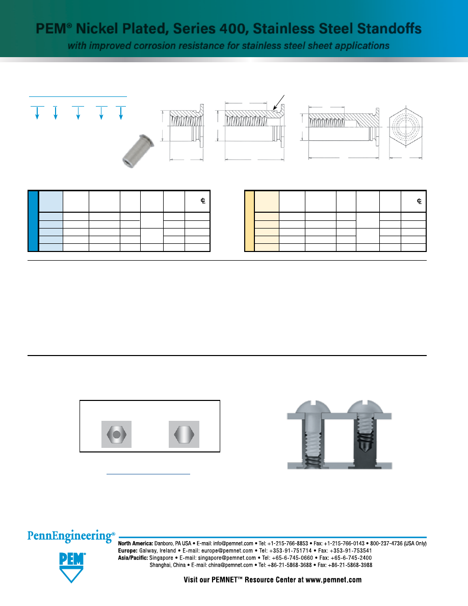
SONP-2
Technical support e-mail: techsupport@pemnet.com
All PEM® products meet our stringent quality standards. If you require additional industry or other specific quality certifications, special procedures and/or part
numbers are required. Please contact your local sales office or representative for further information.
Regulatory compliance information is available in Technical Support section of our website. Specifications subject to change without notice. See our website for the
most current version of this bulletin.
© 2016 PennEngineering.
TYPE TSO4™ THREADED STANDOFFS FOR SHEETS AS THIN AS .025”/0.63mm
C
F
H
L
Blind
ME
TR
IC
U
NIF
IE
D
Min.
Hole Size
C
F Min.
Min. Dist.
Thread
Sheet
In Sheet
+.000
Thread
H
Hole
C/
Code
Thickness +.003 -.000
-.005
Depth
Nom.
To Edge
256 .025 .166 .165
.200
.187 .23
6256 .025 .213 .212 .250 .27
440 .025 .166 .165
.220
.187 .23
6440 .025 .213 .212 .250 .27
632 .025 .213 .212 .270 .250 .27
Min.
Hole Size
F Min.
Min. Dist.
Thread
Sheet
In Sheet
C
Thread
H
Hole
C/
Code
Thickness
+0.08
-0.13
Depth
Nom.
To Edge
M25 0.63 4.22 4.2
5.2
4.8 5.8
6M25 0.63 5.41 5.39 6.4 7.1
M3 0.63 4.22 4.2
6.2
4.8 5.8
6M3 0.63 5.41 5.39 6.4 7.1
M35 0.63 5.41 5.39 7 6.4 7.1
All dimensions are in millimeters.
GENERAL DIMENSIONAL DATA
Thru-threaded
C
L
Clinching profile may vary.
Partially Threaded
C
F
L
Single Groove
Registered
Trademark
TSO 4 – 440 – 250 NC
PART NUMBER DESIGNATION
Material
Code
Thread
Code
Length
Code
Type
Finish
All dimensions are in inches.
PEM® self-clinching standoffs, which use the proven self-clinching design, provide ideal solutions for applications where
mounting, spacing or stacking of panels, boards or components are required. Pressed into round holes, these fasteners
mount permanently into metal sheets as thin as .025”/0.63mm.
Thru-hole
HEAD SIDE OF SHEET AFTER INSTALLATION
Blind
For more information on how to use PEM® self-clinching standoffs,
see Tech Sheet “
PEM®-Ref/Standoff Basics
” on our web site.
Through-hole
Blind
Support
this sheet
For combination thread size and
length selection available,
see PEM® Bulletin SO.
(1) Not stocked, available on special order. Minimum quantities apply. Contact your local PEM distributor for details. See PEM Technical Support section
of our web site for related plating standards and specifications.
(2) HRB - Hardness Rockwell “B” Scale. HB - Hardness Brinell.
TYPES SO4/BSO4/TSO4 MATERIAL AND FINISH SPECIFICATIONS
Threads:
Internal, ASME B1.1, 2B ASME B1.13M, 6H
Fastener material:
Hardened 400 Series Stainless Steel
Finish:
NC - Electroless Nickel over Copper over Nickel strike per ASTM B733
(1)
For use in:
Sheet hardness HRB 88 / HB 183 or less
(2)
PEM® Nickel Plated, Series 400, Stainless Steel Standoffs
with improved corrosion resistance for stainless steel sheet applications
pem-html.html
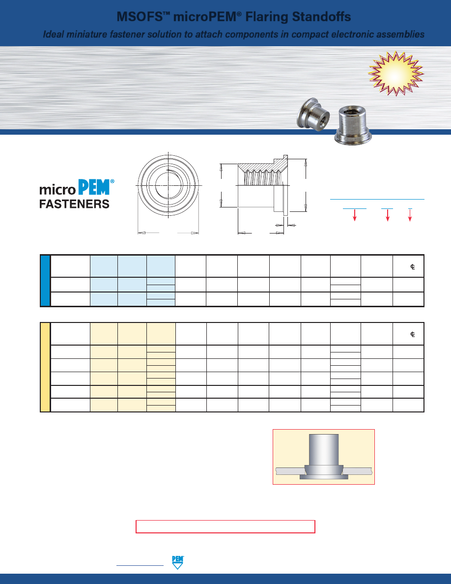
U
NIF
IE
D
Hole
Size
Min.
Dist.
Thread
Thread
Length
Sheet
in Sheet
C
D
H
L
T
Hole
CL
Size
Type Code Code
Thickness
+.002 –.000
Max.
Max.
Nom.
+.002 –.003
±.002
to Edge
.060-80
MSOFS 080
3
.008 - .012
.118
.094
.117
.138
.093 .010 .069
(#0-80)
(1)
4
.125
.086-56
MSOFS 256
3
.008 - .012
.138
.113
.137
.157
.093 .010 .079
(#2-56)
(1)
4
.125
All dimensions are in inches.
ME
TR
IC
Thread
Hole Size
Min. Dist.
Size x
Thread
Length
Sheet
in Sheet
C
D
H
L
T
Hole
CL
Pitch
Type Code Code
Thickness
+0.05
Max.
Max.
Nom.
+0.05 –0.08
±0.05
to Edge
M1 x 0.25
(2)
MSOFS M1 2
0.2 - 0.3
3
2.39
2.97
3.35 2 0.25 1.75
3 3
M1.2 x 0.25
(2)
MSOFS M1.2 2 0.2 - 0.3
3
2.39
2.97
3.35 2 0.25 1.75
3 3
M1.4 x 0.3
(3)
MSOFS M1.4 2 0.2 - 0.3
3
2.39
2.97
3.35 2 0.25 1.75
3 3
M1.6 x 0.35
(4)
MSOFS M1.6 2 0.2 - 0.3
3.5
2.87
3.48
4 2 0.25 2
3 3
M2 x 0.4
(4)
MSOFS M2 2
0.2 - 0.3
3.5
2.87
3.48
4 2 0.25 2
3 3
All dimensions are in millimeters.
Threads:
(1) Internal, ASME B1.1, 2B
(2) Metric ISO 68-1, 5H
(3) Metric ISO 68-1, 6H
(4) Metric ASME B1.13M, 6H
Material:
300 series stainless steel
Standard Finish:
Passivated and/or tested per ASTM A380
For use in:
Any panel hardness
H
C
T
L
D
MSOFS™ microPEM® Flaring Standoffs
•
New MSOFS™ microPEM® flaring standoffs attach permanently in panels as thin as
.008”/0.2 mm of any hardness, including stainless steel.
•
Can be installed into any type of panel, including metal, plastic and P.C. Board.
•
Flaring feature allows for installation into multiple panels.
•
Small footprint allows for reduced centerline-to-edge designs.
•
Threads as small as #0-80/M1.
MSOFS-118
Ideal miniature fastener solution to attach components in compact electronic assemblies
MSOFS – 080 – 3
PART NUMBER DESIGNATION
Thread
Code
Length
Code
Type and
Material
MSOFS™ standoff installed.
Fastener drawings and models are available at
www.pemnet.com
NEW!
© 2017 PennEngineering.
MSOFS-1
PennEngineering •
www.pemnet.com
pem-html.html
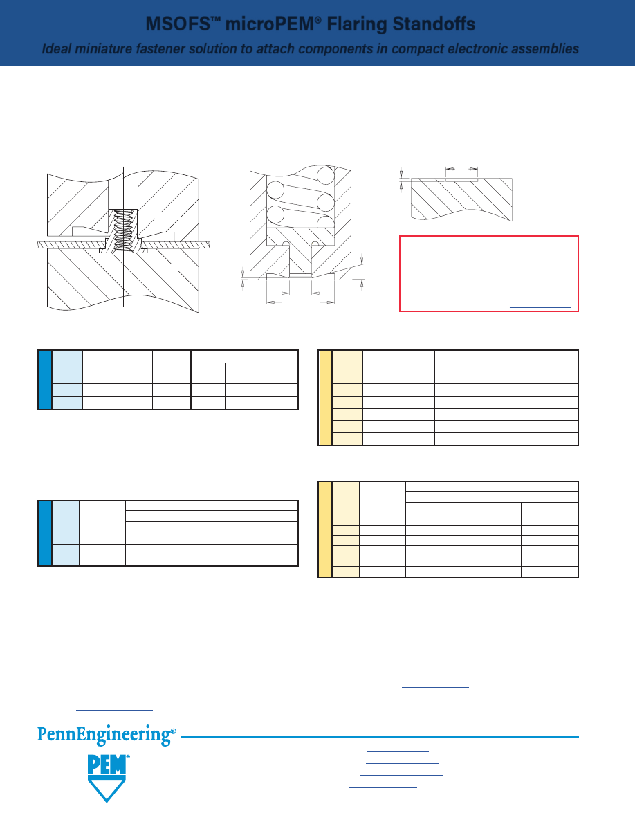
U
NIF
IE
D
(1) Published installation forces are for general reference. Actual set-up and confirmation of complete installation should be made by observing
proper seating of fastener as described in the installation steps. Other performance values reported are averages when all proper
installation parameters and procedures are followed. Variations in mounting hole size, sheet material, and installation procedure may affect
performance. Performance testing this product in your application is recommended. We will be happy to provide technical assistance and/
or samples for this purpose.
PEMSERTER® Installation Tooling
INSTALLATION
1.
Prepare properly sized mounting hole in sheet. Do not perform any secondary operations such as deburring.
2.
Place the standoff into anvil recess and place the mounting hole over the standoff as shown in the drawing.
3.
Using a punch flaring tool and a recessed anvil, apply squeezing force until punch contacts the sheet.
PERFORMANCE DATA
(1)
U
NIF
IE
D
Max. Rec.
Test Sheet Material
Thread Tightening
.008” 300 Series Stainless Steel
Code
Torque For
Mating Screw
Installation
Pushout
Torque-out
(in. lbs.)
(lbs.)
(lbs.)
(in.lbs.)
080 .65
1500
69.8
1.29
256 1.3
1800
91.2
1.29
ME
TR
IC
Max. Rec.
Test Sheet Material
Thread Tightening
0.2 mm 300 Series Stainless Steel
Code
Torque For
Mating Screw
Installation
Pushout
Torque-out
(N•m)
(kN)
(N)
(N•m)
M1 0.019
6.67
311
0.146
M1.2
0.036
6.67
311
0.146
M1.4
0.057
6.67
311
0.146
M1.6
0.084
8
406
0.146
M2 0.175
8
406
0.146
Thread
Punch Dimensions (in.) Anvil Dimensions (in.)
Code
C
Punch Part
A
B
Anvil Part
+.001
Number ±.001 ±.001 Number
080
.095
8020712 .143 .006 8019720
256
.114
8020710
.163
.006
8019722
ME
TR
IC
Thread
Punch Dimensions (mm) Anvil Dimensions (mm)
Code
C
Punch Part
A
B
Anvil Part
+0.025
Number ±.025 ±.025 Number
M1
2.41
8020712 3.64 0.15 8019720
M1.2
2.41
8020712
3.64
0.15
8019720
M1.4
2.41
8020712
3.64
0.15
8019720
M1.6
2.9
8020710
4.14
0.15
8019722
M2
2.9
8020710
4.14
0.15
8019722
BEFORE
AFTER
PUNCH DETAIL
ANVIL DETAIL
A
B
Punch
Anvil
C
Ø .250”/
6.35 mm Min.
15
˚
Nom.
.004” ±.001”/
0.1 mm ±0.25 mm
MSOFS-2
All PEM® products meet our stringent quality standards. If you require additional industry or other specific
quality certifications
, special procedures and/or part
numbers are required. Please contact your local sales office or representative for further information.
Regulatory
compliance information
is available in Technical Support section of our website. Specifications subject to change without notice. See our website for the
most current version of this bulletin.
North America:
Danboro, Pennsylvania USA
•
E-mail:
info@pemnet.com
•
Tel: +1-215-766-8853
•
800-237-4736 (USA)
Europe:
Galway, Ireland
•
E-mail:
europe@pemnet.com
•
Tel: +353-91-751714
Asia/Pacific:
Singapore
•
E-mail:
singapore@pemnet.com
•
Tel: +65-6-745-0660
Shanghai, China
•
E-mail:
china@pemnet.com
•
Tel: +86-21-5868-3688
Visit our PEMNET™ Resource Center at
www.pemnet.com
•
Technical support e-mail:
techsupport@pemnet.com
INSTALLATION NOTES
•
For best results we recommend using a
PEMSERTER® press for installation of PEM self-
clinching fasteners. Please check our website
for more information.
•
Visit the Animation Library on our website to
view the installation process
for select products
.
MSOFS™ microPEM® Flaring Standoffs
Ideal miniature fastener solution to attach components in compact electronic assemblies
pem-html.html
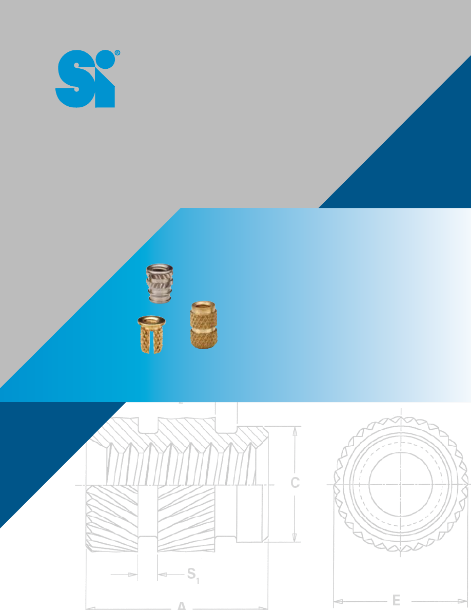
SI
®
THREADED INSERTS
FOR PLASTICS
SI® brand inserts employ press-in,
molded-in, or heat/ultrasonic installation
methods to provide strong, reusable,
permanent threads in plastic.
Bulletin SI-1017
pem-html.html
SI-2
PennEngineering •
www.pemnet.com
SI® INSERTS FOR PLASTICS
PART NUMBER DESIGNATION AND MATERIAL AND FINISH SPECIFICATIONS
IU B - 440 - 2
Length Code (where applicable):
See individual product charts for actual corresponding dimensional lengths.
Thread Code:
Internal, ASME B1.1, 2B / ASME B1.13M, 6H (except where noted)
For PPB, PFLB, and PKB inserts collapsed slot and burrs may cause prevailing
torque while thread accepts class 3A/4h screw.
See individual product charts for actual corresponding thread size.
Material Code:
B = Free-machining, leaded brass. Plain finish. Meets RoHS requirements.
C = 300 series stainless steel. Passivated and/or tested per ASTM A380.
A = Aluminum. Plain finish.
Type:
IU
=
Ultrasonic,
tapered
IUT = Ultrasonic, straight wall
IS
=
Ultrasonic,
symmetrical
MSI = microPEM®, Ultrasonic, symmetrical
IB = Molded-in, blind threaded
IBL = Molded-in, self-locking blind threaded
IT
=
Molded-in,
thru-threaded
STK
=
Molded-in,
knurled
NFP
=
Press-in,
hexagonal
PP
=
Press-in,
thru-threaded
PFL
=
Press-in,
flange-head
PK = Press-in, straight knurl
•
SI® inserts are typically specified in applications where strong, durable metal threads are required in plastic material,
especially where frequent assembly and disassembly of the unit for service or repair is necessary.
•
Applications for SI® products include: electronics (including wearables, smart phones and hand held devices),
automotive, aerospace and defense, medical, transportation, industrial and recreational equipment.
•
SI® inserts are available in brass, stainless steel and aluminum.
•
SI® inserts are available in a large variety of ultrasonic / heat staking, molded-in or press-in types.
•
Aluminum and stainless steel inserts for plastics offer lead-free alternatives to leaded brass typically used for brass
inserts.
–
Lead-free inserts offer alternative to leaded brass to address environmental and end-of-life recycling concerns.
–
NEW aluminum inserts
are approximately 70% lighter than brass equivalents and made from lead-free aluminum.
–
Stainless steel inserts are typically stronger than brass and may offer better protection from certain types of
corrosive agents.
•
SI® microPEM® inserts provide threads as small as M1.
Featuring
threads as
small as M1
Lead-free,
Lightweight,
Aluminum
Inserts
Insert drawings
and models are
available at
www.pemnet.com
pem-html.html
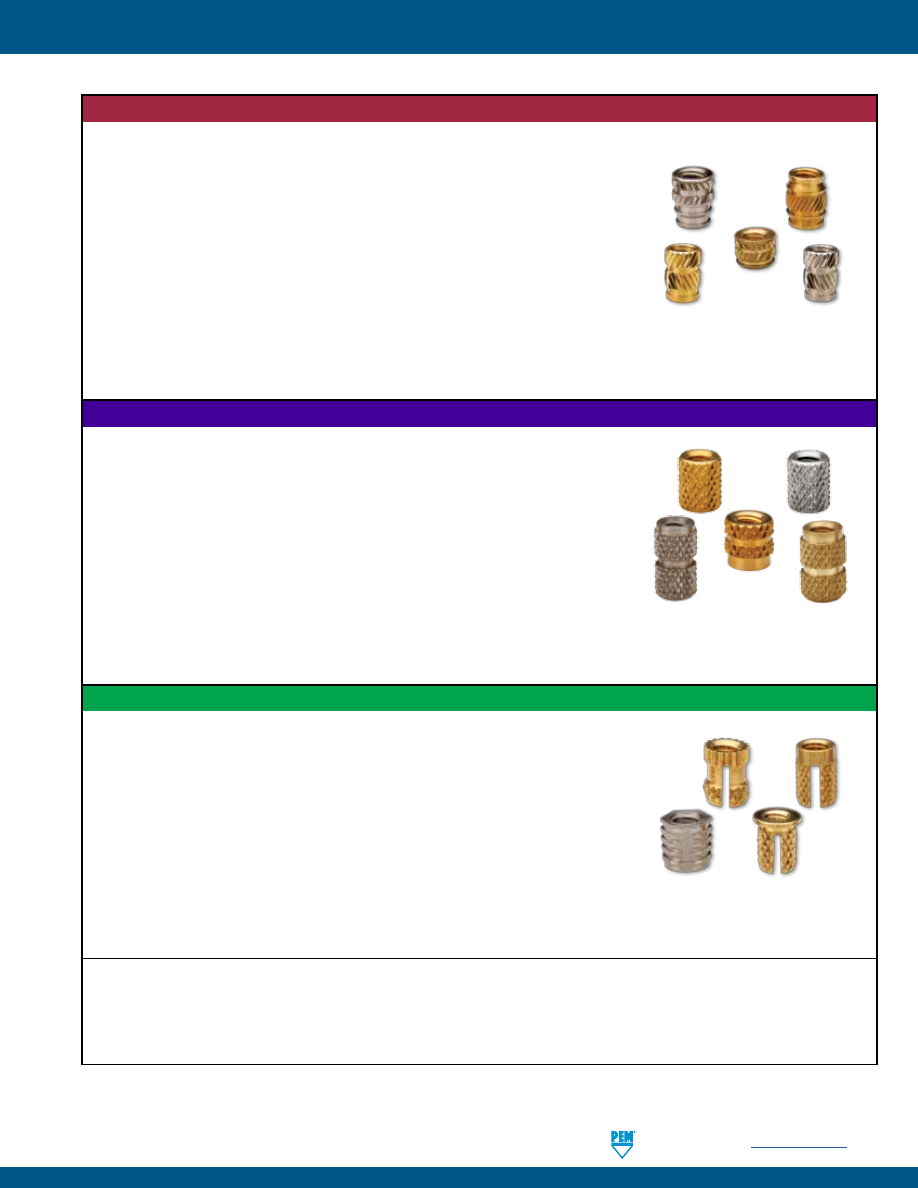
PennEngineering •
www.pemnet.com
SI-3
SI® INSERTS FOR PLASTICS
ULTRASONIC / HEAT STAKING INSERTS
•
Ultrasonic - Installed by pressing the insert into the mounting hole with
ultrasonic insertion equipment while simultaneously applying a high
frequency vibration. Frictional heat caused by the vibration melts the plastic
surrounding the insert allowing easy insertion. When the vibration ceases, the
plastic solidifies, locking the insert permanently in place.
•
Heat Staking - Installed by pressing the insert into the mounting hole with a
thermal press to melt the plastic surrounding the insert.
IUA, IUB, IUC
(Tapered, through threaded inserts) -
Page 4
IUTA, IUTB, IUTC
(Straight wall, through threaded inserts) -
Page 5
ISA, ISB, ISC
(Symmetrical, through threaded inserts) -
Page 6
MSIA, MSIB
(microPEM® symmetrical, through threaded inserts) -
Page 7
Performance data for ultrasonic inserts -
Page 8
MOLDED-IN INSERTS
•
Installed during the molding process, the inserts are located in the mold
cavity by core pins. When the mold opens, the core pins are withdrawn
leaving the inserts permanently encapsulated in the plastic section with only
the threads exposed.
•
Installing the inserts during the molding process eliminates the need for
secondary steps or installation equipment.
IBA, IBB, IBC
(Blind threaded inserts) -
Page 9
IBLC
(Self-locking blind threaded inserts) -
Page 10
ITA, ITB, ITC
(Through threaded inserts) -
Page 11
STKA, STKB, STKC
(Knurled spacers) -
Page 12
Performance data for molded-in inserts -
Page 13
PRESS-IN INSERTS
•
Installed by simply pressing the inserts into pre-molded or drilled holes.
Installation is accomplished using any standard press at any time during the
production process.
•
Eliminates the need for molding-in inserts.
•
Eliminates the need for heat or ultrasonic equipment.
NFPC, NFPA
(Hexagonal, press-in inserts) -
Page 14
PPA, PPB
(Through threaded inserts) -
Page 15
PFLA, PFLB
(Flange-head inserts) -
Page 16
PKA, PKB
(Straight knurl inserts) -
Page 17
Performance data for press-in inserts -
Page 18
SI® Custom Designs
-
Page 19
Hole Preparation Guidelines -
Page 19
SI® Prototype Kit -
Page 20
pem-html.html
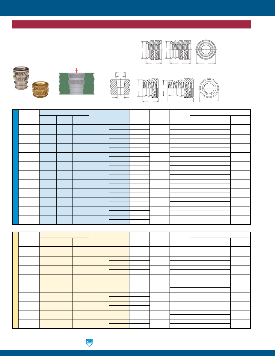
SI-4
PennEngineering •
www.pemnet.com
SI® INSERTS FOR PLASTICS
ULTRASONIC / HEAT STAKING INSERTS
ME
TR
IC
U
NIF
IE
D
Type
Hole Size in Material
Thread
New
Thread
Length A E
C
Size Aluminum Brass
Stainless
Code
Code ± .005
± .005
±.005
Min. Hole
D
F
Steel
(1)
Depth
± .002
± .002
.060-80
IUA IUB IUC 080 1 .115 .141 .123 .155 .118 .123
(#0-80)
2
.188
.115
.228
.107
.086-56
IUA IUB IUC 256 1 .115 .141 .123 .155 .118 .123
(#2-56)
2
.188
.115
.228
.107
.112-40
IUA IUB IUC 440 1 .135 .172 .157 .175 .153 .159
(#4-40)
2
.219
.149
.259
.141
.138-32
IUA IUB IUC 632 1 .150
.219 .203 .190 .199 .206
(#6-32)
2
.250
.190
.290
.185
.164-32
IUA IUB IUC 832 1 .185
.250 .230 .225 .226 .234
(#8-32)
2
.312
.213
.352
.208
.190-24
IUA IUB IUC 024 1 .225
.297 .272 .265 .267 .277
(#10-24)
2
.375
.251
.415
.246
.190-32
IUA IUB IUC 032 1 .225
.297 .272 .265 .267 .277
(#10-32)
2
.375
.251
.415
.246
.250-20
IUA IUB IUC 0420 1 .300 .375 .354 .340 .349 .363
(1/4-20)
2 .500 .332 .540 .321
.250-28
IUA IUB IUC 0428 1 .300 .375 .354 .340 .349 .363
(1/4-28)
2
.500
.332
.540
.321
.313-18
IUA IUB IUC 0518 1 .335
.469 .439 .375 .431 .448
(5/16-18)
2
.562
.406
.602
.401
.375-16
IUA IUB IUC 0616 1 .375
.563 .532 .415 .523 .540
(3/8-16)
2
.625
.493
.665
.488
(1) Thread tapped thru, Class 3A/4h screw must pass with finger torque, but basic go gauge may stop at last thread.
Tapered Thru-Threaded, IUA™, IUB™ and IUC™ Inserts
•
Designed for use in tapered holes.
•
Tapered mounting hole allows for rapid and accurate alignment
prior to installation.
•
Aluminum inserts ideal for light weight designs.
•
Aluminum and stainless steel inserts offer lead-free alternative.
Type
Thread
Hole Size in Material
Thread
New
Code
Length A E
C
Size x
Aluminum Brass
Stainless
(1)
Code
± 0.13
± 0.13
±0.13
Min. Hole
D
F
Pitch
Steel
Depth
± 0.05
± 0.05
M2.5 x 0.45
IUA
IUB
IUC
M2.5 1 3.43 4.37 3.99 4.44 3.89 4.04
2 5.56 3.79
6.58
3.58
M3 x 0.5
IUA
IUB
IUC
M3 1 3.43
4.37 3.99 4.44 3.89 4.04
2 5.56 3.79
6.58
3.58
M3 x 0.5
IUAA
IUBB
IUCC
M3 1 3.81
5.56 5.16 4.83 5.05 5.23
2 6.35 4.83
7.42
4.7
M3.5 x 0.6
IUA
IUB
IUC
M3.5 1 3.81 5.56 5.16 4.83 5.05 5.23
2 6.35 4.83
7.42
4.7
M4 x 0.7
IUA
IUB
IUC
M4 1 4.7
6.35 5.84 5.72 5.74 5.94
2 7.92 5.41
8.94
5.28
M5 x 0.8
IUA
IUB
IUC
M5 1 5.72
7.54 6.91 6.74 6.78 7.03
2 9.53 6.38
10.55
6.25
M5 x 0.8
IUAA
IUBB
IUCC
M5 1 6.71
8.33 7.83 7.72 7.7 8
2 11.1 7.16 12.12
7.06
M6 x 1
IUA
IUB
IUC
M6 1 7.62
9.52 8.99 8.64 8.86 9.22
2 12.7 8.43
13.72
8.15
M8 x 1.25
IUA
IUB
IUC
M8 1 8.51
11.91 11.15 9.53 10.95 11.38
2 14.27 10.31
15.29
10.19
-1 Length Code
-2 Length Code
A
A
C
E
C
After Knurl
All dimensions are in inches.
All dimensions are in millimeters.
Install
8°
F
D
Mounting Hole
-1 Length Code
-2 Length Code
A
A
C
E
C
After Knurl
Diagonal Knurl
Thread sizes
4-40 to 3/8-16
and M2.5 to M8
Diamond Knurl
Thread sizes
0-80 & 2-56
pem-html.html
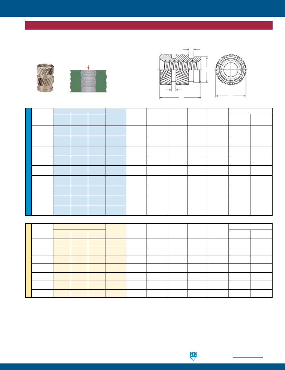
PennEngineering •
www.pemnet.com
SI-5
SI® INSERTS FOR PLASTICS
ME
TR
IC
U
NIF
IE
D
Type Thread
Hole Size in Material
Thread Code A E C
S
1
S
2
Min. Hole
Hole Dia.
Size
New
Brass
Stainless
(1)
± .005
± .009
±.005
Nom. Nom.
Depth
+ .003
Aluminum Steel
- .000
.086-56
IUTA
IUTB IUTC 256
.157 .147
.121
.031 .031
.187
.127
(#2-56)
.112-40
IUTA
IUTB IUTC 440 .226 .179
.152 .031 .031
.256
.158
(#4-40)
.138-32
IUTA
IUTB IUTC 632
.281 .210 .183 .031 .031
.311
.189
(#6-32)
.164-32
IUTA
IUTB IUTC 832
.321 .243 .217 .031 .040 .351
.223
(#8-32)
.190-24
IUTA
IUTB IUTC 024
.375 .273 .247 .046 .046 .405
.253
(#10-24)
.190-32
IUTA
IUTB IUTC 032
.375 .273 .247 .046 .046 .405
.253
(#10-32)
.250-20
IUTA
IUTB IUTC 0420 .500 .342 .310 .046 .062 .530
.316
(1/4-20)
.250-28
IUTA
IUTB IUTC 0428 .500 .342 .310 .046 .062 .530
.316
(1/4-28)
.375-16
IUTA
IUTB IUTC 0616 .500 .509 .462 .046 .062 .530
.468
(3/8-16)
(1) Thread tapped thru, Class 3A/4h screw must pass with finger torque, but basic go gauge may stop at last thread.
Straight Wall, Thru-Threaded, IUTA™, IUTB™ and IUTC™ Inserts
•
Self-aligning lead-in of insert provides for accurate alignment prior to installation.
•
Aluminum inserts ideal for light weight designs.
•
Aluminum and stainless steel inserts offer lead-free alternative.
Thread Type Thread
Hole Size in Material
Size x
New
Stainless
Code
A E C
S
1
S
2
Min. Hole
Hole Dia.
Pitch Aluminum Brass
Steel
(1)
± 0.13
± 0.23
±0.13
Nom. Nom.
Depth
+ 0.08
M2 x 0.4
IUTA
IUTB
IUTC
M2
4
3.73
3.07
0.79
0.79
4.76
3.23
M2.5 x 0.45
IUTA
IUTB
IUTC
M2.5
5.74
4.55
3.86
0.79
0.79
6.5
4.01
M3 x 0.5
IUTA
IUTB
IUTC
M3
5.74
4.55
3.86
0.79
0.79
6.5
4.01
M3.5 x 0.6
IUTA
IUTB
IUTC
M3.5
7.14
5.33
4.65
0.79
0.79
7.9
4.81
M4 x 0.7
IUTA
IUTB
IUTC
M4
8.15
6.17
5.51
0.79
1.02
8.91
5.67
M5 x 0.8
IUTA
IUTB
IUTC
M5
9.52
6.93
6.27
1.17
1.17
10.28
6.43
M6 x 1
IUTA
IUTB
IUTC
M6
12.7
8.69
7.87
1.17
1.58
13.46
8.03
S
2
S
1
C
A
E
After Knurl
All dimensions are in inches.
All dimensions are in millimeters.
Install
ULTRASONIC / HEAT STAKING INSERTS
pem-html.html
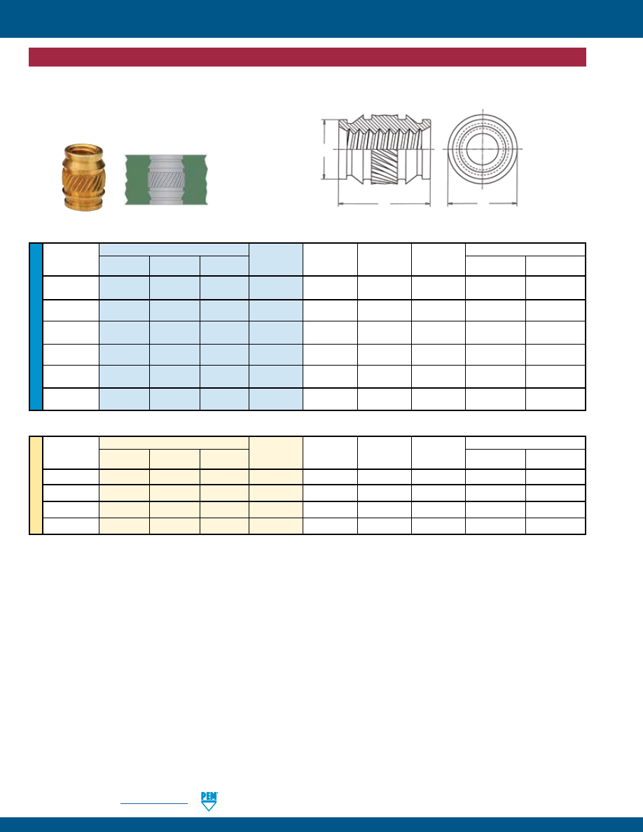
SI-6
PennEngineering •
www.pemnet.com
SI® INSERTS FOR PLASTICS
ME
TR
IC
U
NIF
IE
D
Type
Thread
Hole Size in Material
Thread
New
Brass
Stainless Code
A E C
Hole
Hole Dia.
Size
Aluminum Steel (1)
± .005
± .005
± .003
Depth +.003-.000
.086-56
ISA ISB ISC 256 .157 .151 .122 .187 .126
(#2-56)
.112-40
ISA ISB ISC 440 .226 .182 .153 .256 .157
(#4-40)
.138-32
ISA ISB ISC 632 .281 .215 .184 .311 .188
(#6-32)
.164-32
ISA ISB ISC 832 .321 .245 .217 .351 .221
(#8-32)
.190-32
ISA ISB ISC 032 .375 .276 .248 .405 .252
(#10-32)
.250-20
ISA ISB ISC 0420 .500 .338 .311 .530 .315
(1/4-20)
(1) Thread tapped thru, Class 3A/4h screw must pass with finger torque, but basic go gauge may stop at last thread.
Symmetrical, Thru-Threaded, ISA™, ISB™ and ISC™ Inserts
•
Symmetrical design eliminates the need for orientation.
•
Aluminum inserts ideal for light weight designs.
•
Aluminum and stainless steel inserts offer lead-free alternative.
Thread Type Thread
Hole Size in Material
Size x
New
Brass
Stainless
Code
A E C
Hole
Hole Dia.
Pitch
Aluminum Steel
(1)
± 0.13
± 0.13
± 0.08
Depth +0.08
M3 x 0.5
ISA
ISB
ISC
M3
5.74
4.62
3.88
6.5
3.99
M4 x 0.7
ISA
ISB
ISC
M4
8.15
6.22
5.51
8.92
5.62
M5 x 0.8
ISA
ISB
ISC
M5
9.52
7.01
6.3
10.29
6.4
M6 x 1
ISA
ISB
ISC
M6
12.7
8.58
7.9
13.46
8
C
A
E
After Knurl
All dimensions are in inches.
All dimensions are in millimeters.
ULTRASONIC / HEAT STAKING INSERTS
pem-html.html
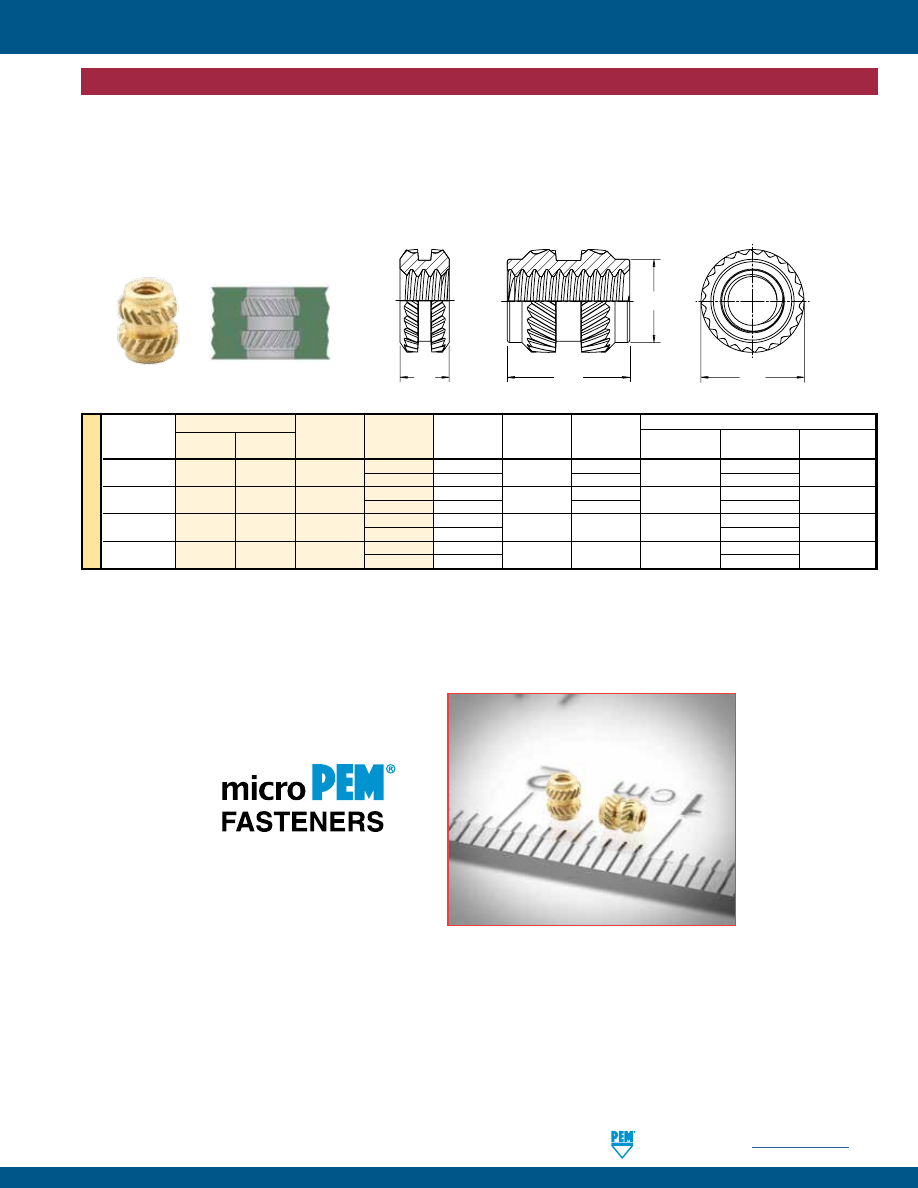
PennEngineering •
www.pemnet.com
SI-7
SI® INSERTS FOR PLASTICS
All dimensions are in millimeters.
microPEM® Symmetrical, Thru-Threaded, MSIA™ MSIB™ Inserts
•
Threads as small as M1.
•
Symmetrical design eliminates the need for orientation.
•
Provides excellent performance in wide range of plastics.
•
Aluminum inserts ideal for light weight designs.
•
Aluminum inserts offer lead-free alternative.
Style #1
Style #2
A
C
E
A
After Knurl
ME
TR
IC
Thread Type
Size x
New
Brass
Thread Length A
E
C
Min. Wall
Hole Depth
Hole Diameter
Pitch Aluminum
Code
Code
±0.1
± 0.1
Max.
Thickness
(6)
Min. +0.05
M1 x 0.25
(3)
MSIA MSIB M1
100
(1)
1 2.1 — 0.7
1.77
1.75
250
(2)
2.5 1.75
3.27
M1.2 x 0.25
(3)
MSIA MSIB M1.2
100
(1)
1 2.1 — 0.7
1.77
1.75
250
(2)
2.5 1.75
3.27
M1.4 x 0.3
(4)
MSIA MSIB M1.4
150
(2)
1.5 2.5 2.15 0.8 2.27
2.15
300
(2)
3
3.77
M1.6 x 0.35
(5)
MSIA MSIB M1.6
150
(2)
1.5 2.5 2.15 0.8 2.27
2.15
300
(2)
3
3.77
(1)
Style #1
- length codes less than 150
(2)
Style #2
- length codes 150 and greater
(3) Metric ISO 68-1, 5H
(4) Metric ISO 68-1, 6H
(5) Metric ASME B1.13M, 6H
(6) Refers to wall diameter of boss as tested in ABS and polycarbonate.
Mounting Hole in Material
ULTRASONIC / HEAT STAKING INSERTS
pem-html.html
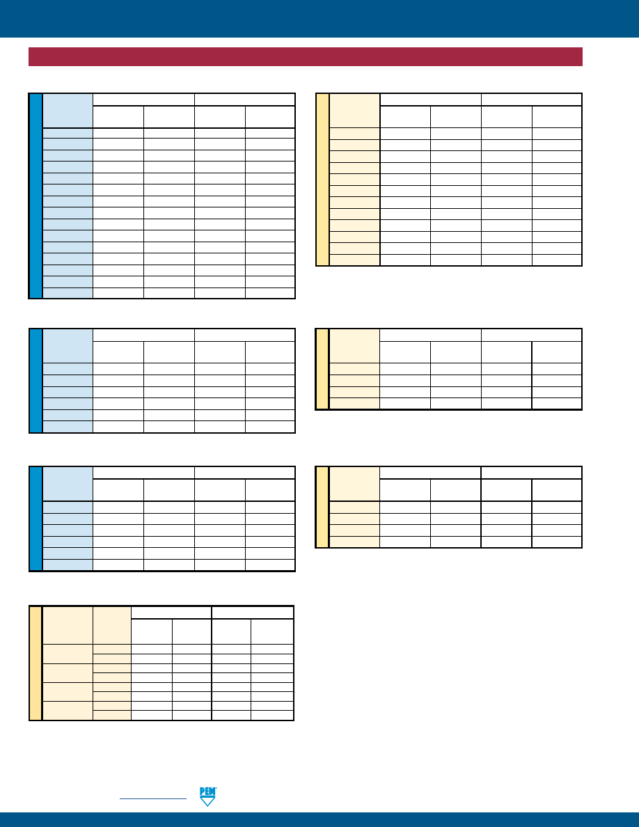
SI-8
PennEngineering •
www.pemnet.com
SI® INSERTS FOR PLASTICS
ME
TR
IC
ME
TR
IC
U
NIF
IE
D
ME
TR
IC
U
NIF
IE
D
U
NIF
IE
D
IUTA, IUTB, IUTC Inserts
(1)
ABS Polycarbonate
Thread Pullout Torque-out Pullout Torque-out
Code
(lbs.)
(in. lbs.)
(lbs.)
(in. lbs.)
256
90
6
112
8
440
165
14
245
16
632
268
25
295
31
832
328
36
385
52
032
385
54
565
80
0420
480
135
600
190
ABS Polycarbonate
Thread Pullout Torque-out Pullout Torque-out
Code (N) (N•m) (N) (N•m)
M2.5/M3
730
1.58
1080
1.81
M4
1450
4.07
1710
5.88
M5
1710
6.1
2510
9.04
M6
2130
15.26
2660
21.47
ISA, ISB and ISC Inserts
(1)
ABS Polycarbonate
Thread Pullout Torque-out Pullout Torque-out
Code
(lbs.)
(in. lbs.)
(lbs.)
(in. lbs.)
256
85.5
6.14
149.4
6.37
440
151.37
14.38
344.94
23.17
632
320.3
21.69
405.9
18.19
832
462.9
31.7
663.9
57.15
032
549.6
52.3
1015.4
71.79
0420
600.45
100.25
–
–
ABS Polycarbonate
Thread Pullout Torque-out Pullout Torque-out
Code (N) (N•m) (N) (N•m)
M3
680
1.62
1550
2.6
M4
2080
3.58
2980
6.45
M5
2470
5.9
4560
8.11
M6
2700
11.1
–
–
ABS
Polycarbonate
Thread
Pullout Torque-out
Pullout Torque-out
Code
(N) (N•m)
(N) (N•m)
M2.5-1
334 0.3
400 0.7
M2.5-2 334
0.3
400
0.7
M3-1
356 0.5
712 0.8
M3-2
356 0.5
712 0.8
M3.5-1
645 1.7
734 2
M3.5-2
1223 1.7
2002 2.7
M4-1
912 2
1312 2.3
M4-2
1646 2.1
2869 2.3
M5-1
1201
5.1
1913
6.2
M5-2
2491
6.8
4048
9
M6-1
1664
7.3
2731
9.6
M6-2
3025
7.3
6294
12.2
IUA, IUB, IUBB, IUC, and IUCC Inserts
(1)
ABS Polycarbonate
Thread Pullout Torque-out Pullout Torque-out
Code
(lbs.)
(in. lbs.)
(lbs.)
(in. lbs.)
080-1
75
3
90
3
256-1
75
3
90
6
256-2
75
3
90
6
440-1
80
4
160
7
440-2
80
4
160
7
632-1
145
15
165
18
632-2
275
15
450
24
832-1
205
18
295
20
832-2
370
19
645
20
024-1
270
45
430
55
024-2
560
60
910
80
032-1
270
45
430
55
032-2 560 60 910 80
0420-1
374
65
614
85
0420-2
680
65
1415
108
(1) The values reported are averages for ultrasonically inserted inserts when
all installation specifications and procedures are followed. Variations
in mounting hole size, sheet material and installation procedure will
affect results. Performance testing of this product in your application is
recommended. Samples can be provided for this purpose
.
(2) Torque-out performance will depend on the strength and type of screw
being used. In most cases, the screw threads will fail before the insert
threads. For testing purposes, inserts were installed using heat stake
equipment into a flat sheet.
MSIA and MSIB Inserts
(1)
ME
TR
IC
ABS
Polycarbonate
Thread
Length
Code
Code Pullout Torque-out Pullout Torque-out
(N)
(N•cm) (2)
(N)
(N•cm) (2)
M1 100 50 3.5 50 4.5
250 150 10 200 12
M1.2 100 50 3.5 50 4.5
250 150 10 200 12
M1.4
150 100 15 140 15
300 330 30 400 30
M1.6 150 100 15 140 15
300 330 30 400 30
PERFORMANCE DATA FOR ULTRASONIC / HEAT STAKING INSERTS
pem-html.html
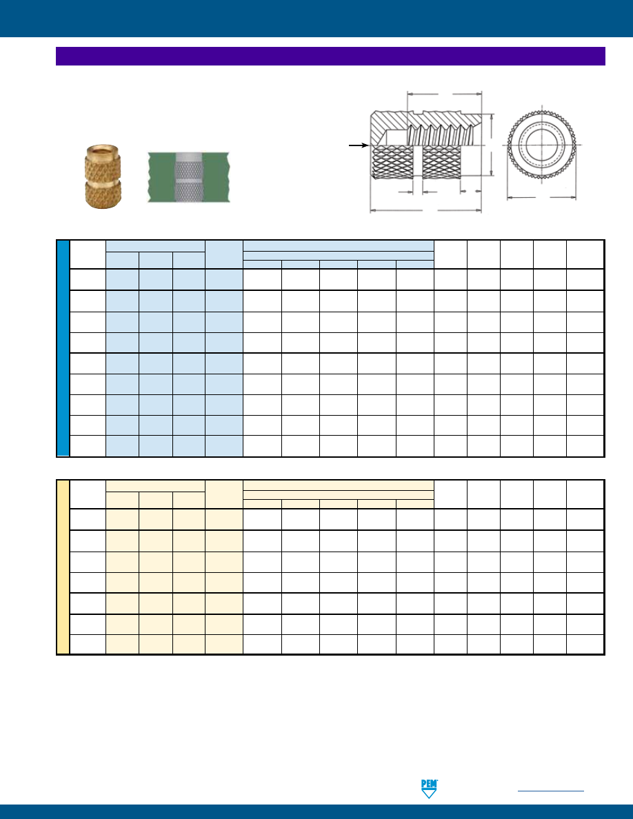
PennEngineering •
www.pemnet.com
SI-9
SI® INSERTS FOR PLASTICS
ME
TR
IC
U
NIF
IE
D
Type
Length A ± .005 / H Min.
Minor
Thread
New
Brass
Stainless
Thread
Min. No. of Full Threads
E C S
1
S
2
Dia.
Size
Aluminum Steel
Code
4 6 8 10 12
Nom.
± .005
Nom.
Nom. Min./Max.
.086-56
IBA IBB IBC
256 .156/.080 .219/.115 .250/.150 .312/.185 .344/.220 .156 .142 .03
.03 .067/.0737
(#2-56)
.112-40
IBA IBB
IBC
440 .205/.110 .281/.160 .344/.210 .406/.260 .438/.310 .188
.171
.03
.03 .086/.0939
(#4-40)
.138-32
IBA IBB
IBC
632
.250/.135 .344/.200 .406/.260 .469/.325 .531/.385 .219
.202
.03
.06 .105/.114
(#6-32)
.164-32
IBA IBB
IBC
832
.250/.135 .344/.200 .406/.260 .469/.325 .531/.385 .250 .226 .05
.06 .131/.139
(#8-32)
.190-24
IBA IBB IBC 024 .356/.175 .438/.260 .531/.345 .625/.425 .716/.510 .281 .259 .05
.06 .146/.156
(#10-24)
.190-32
IBA IBB
IBC
032 .281/.135 .438/.200 .531/.260 .469/.325 .531/.385 .281 .259 .05
.06 .157/.164
(#10-32)
.250-20
IBA IBB
IBC
0420 .344/.200 .531/.315 .625/.415 .719/.515 .819/.615 .344 .321 .06
.09 .197/.207
(1/4-20)
.313-18
IBA IBB
IBC
0518 .438/.235 .594/.345 .719/.460 .811/.570 .949/.680 .438 .404 .078
.094 .254/.265
(5/16-18)
.375-16
IBA IBB
IBC
0616 .500/.265 .688/.390 .812/.515 .935/.640 1.00/.765 .500 .466 .094
.094 .309/.321
(3/8-16)
Blind Threaded, IBA™, IBB™ and IBC™ Inserts
•
Blind-end protects the threads from plastic intrusion
.
•
Aluminum inserts ideal for light weight designs.
•
Aluminum and stainless steel inserts offer lead-free alternative.
NOTE:
Manufacturing
techniques may leave a
slight projection a maximum
of .025” / 0.65 mm beyond
the “A” dimension.
Thread
Type
Length A ± 0.13 / H Min.
Minor
Size x
New
Brass
Stainless
Thread
Min. No. of Full Threads
E C S
1
S
2
Dia.
Pitch Aluminum Steel
Code
4 6 8 10 12
Nom.
± 0.13
Nom.
Nom. Min./Max.
M2.5 x 0.45 IBA
IBB
IBC
M2.5 4.78/2.01 6.35/2.87 7.14/3.74 9.53/4.6 10.31/5.47 4.78 4.34
0.8
0.8 2.03/2.14
M3 x 0.5
IBA
IBB
IBC
M3
5.21/2.21
7.13/3.21
8.73/4.21
10.31/5.21
11.13/6.21
4.78
4.34
0.8
0.8
2.47/2.59
M3.5 x 0.6
IBA
IBB
IBC
M3.5
6.35/2.62
8.73/3.81
10.31/5.02
11.91/6.22
13.48/7.42
5.56
5.13
0.8
1.6
2.87/3.01
M4 x 0.7
IBA
IBB
IBC
M4
6.35/3.08
8.73/4.47
10.31/5.89
11.91/7.29
13.48/8.69
6.35
5.74
1.2
1.6
3.25/3.42
M5 x 0.8
IBA
IBB
IBC
M5
7.13/3.49
11.12/5.09
13.48/6.69
11.91/8.29 13.48/9.89
7.14
6.57
1.2
1.6
4.15/4.34
M6 x 1
IBA
IBB
IBC
M6
8.73/4.37
13.49/6.37
15.87/8.37
18.26/10.57 20.8/12.37 8.74
8.15
1.6
2.4 4.94/5.16
M8 x 1.25
IBA
IBB
IBC
M8
11.13/5.72
15.09/7.82
18.24/10.32 20.62/12.82 22.23/15.32 11.13 10.26 1.98 2.4 6.68/6.92
H
C
A
E
Stock Diameter
(Before Knurl)
S
2
S
1
All dimensions are in inches.
All dimensions are in millimeters.
MOLDED-IN INSERTS
pem-html.html
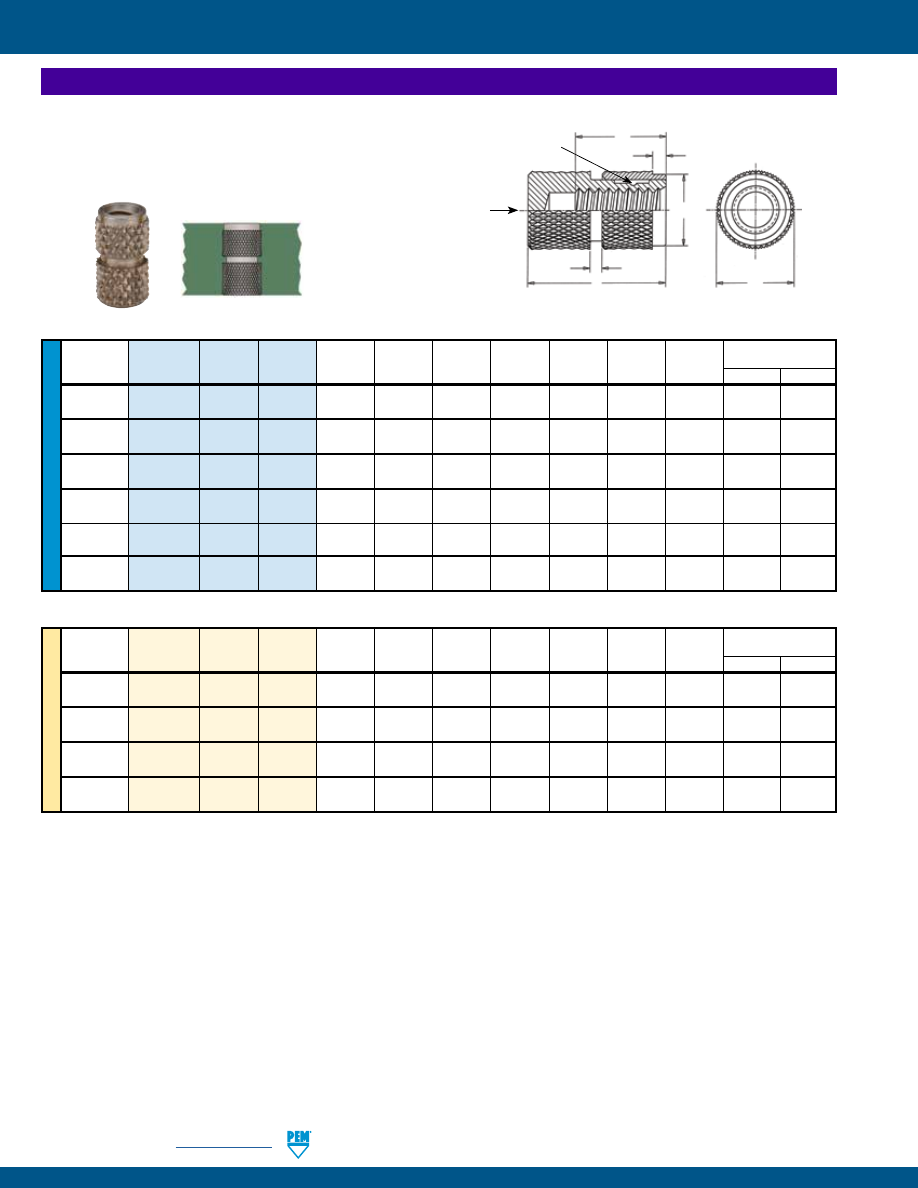
SI-10
PennEngineering •
www.pemnet.com
SI® INSERTS FOR PLASTICS
ME
TR
IC
U
NIF
IE
D
(1)
First Cycle on Locking
Thread Type Thread Length A E
C
S
1
S
2
Minor Dia.
H Torque (in. lbs.) (2)
Size Code
Code
± .005
Nom.
± .005
± .005
± .005 Min/Max Min.
Min. Max.
.086-56
IBLC
256
8
.250 .156 .150 .03
.03 .067/.0737 .150 0.2 2.5
(#2-56)
.112-40
IBLC
440
8
.344 .188 .180
.03
.03 .086/.0939 .210
0.5
5
(#4-40)
.138-32
IBLC 632 8
.406 .219 .200 .03 .03 .105/.114 .260 1 10
(#6-32)
.164-32
IBLC 832 8 .406 .250 .235 .05 .06 .131/.139 .260 1.5 15
(#8-32)
.190-32
IBLC 032
8
.531 .281 .270 .05 .06 .157/.164 .260 2 18
(#10-32)
.250-20
IBLC 0420 8
.625 .344 .325 .06 .09 .197/.207 .415 4.5 30
(1/4-20)
(1) Minor diameter may be below minimum in deformed thread area.
(2) Locking torque values shown apply when the mating screw has thread class of 3A for unified sizes and class 4h for metric sizes and is made from 300
series stainless steel with no additive finish. Other screws may be used, but the locking torque may not comply with the values shown.
Self-Locking, Blind Threaded, IBLC™ Inserts
•
Deformed threads create prevailing torque locking feature
to prevent screw loosening due to vibration.
•
Blind-end protects the threads from plastic intrusion.
•
Stainless steel inserts offer lead-free alternative.
Thread
(1)
First Cycle on Locking
Size x
Type
Thread Length A
E
C
S
1
S
2
Minor Dia.
H Torque (N•m) (2)
Pitch
Code
Code
± 0.13
Nom.
± 0.13
± 0.13
± 0.13 Min/Max Min.
Min. Max.
M3 x 0.5
IBLC
M3
8
8.73
4.78
4.57
0.8
0.8
2.48/2.59
4.21
0.06
0.6
M4 x 0.7
IBLC
M4
8
10.31
6.35
5.97
1.2
1.6
3.26/3.42
5.89
0.16
1.6
M5 x 0.8
IBLC
M5
8
13.48
7.14
6.86
1.2
1.6
4.15/4.34
6.69
0.23
2.1
M6 x 1
IBLC
M6
8
15.87
8.73
8.26
1.6
2.4
4.95/5.15
8.37
0.37
3.2
All dimensions are in inches.
All dimensions are in millimeters.
H
Deformed thread
for self-locking
feature
C
A
E
S
2
S
1
Stock Diameter
(Before Knurl)
NOTE:
Manufacturing
techniques may leave a
slight projection a maximum
of .025” / 0.65 mm beyond
the “A” dimension.
MOLDED-IN INSERTS
pem-html.html
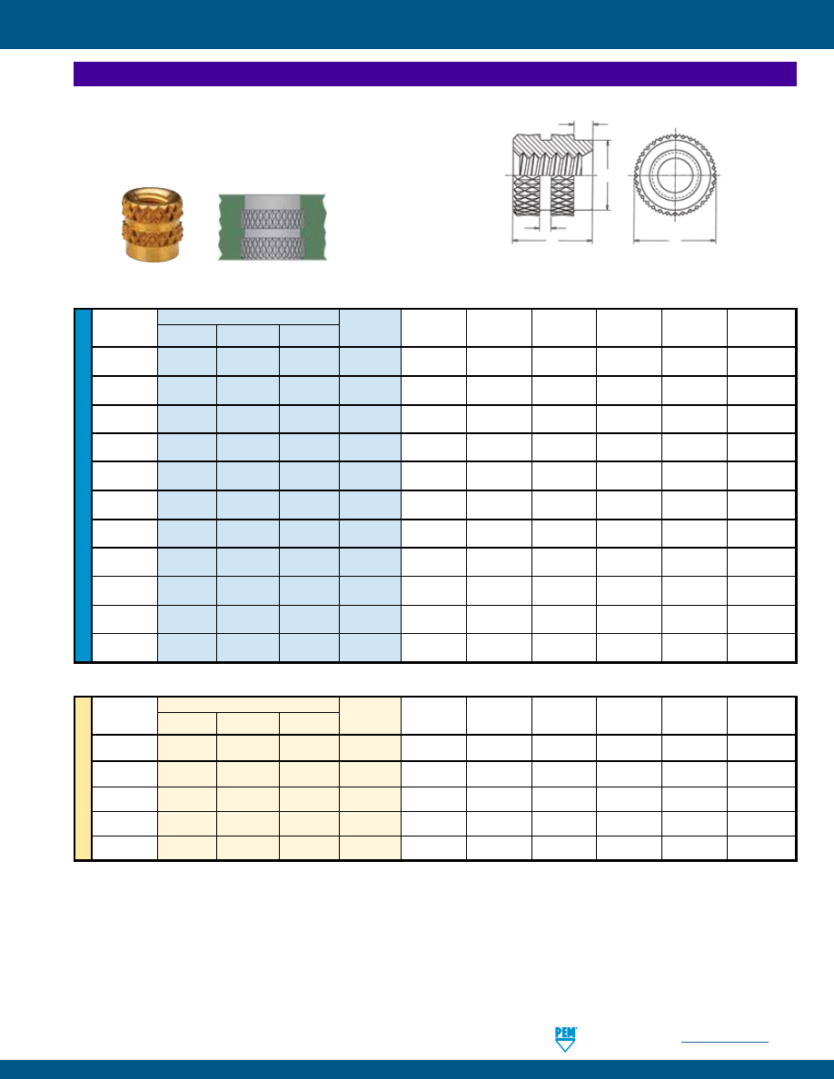
PennEngineering •
www.pemnet.com
SI-11
SI® INSERTS FOR PLASTICS
ME
TR
IC
U
NIF
IE
D
Type
Thread
Thread
New
Stainless
Code A E
C
S
1
S
2
Minor Dia.
Size
Aluminum
Brass
Steel
(1)
± .005
Nom.
± .005
Nom. Nom. Min./Max.
.060-80
ITA
ITB ITC 080 .125 .109 .078 .03
.03 .0475/.051
(#0-80)
.086-56
ITA ITB ITC 256 .125 .156 .142 .03
.03 .067/.0737
(#2-56)
.112-40
ITA ITB ITC 440 .188 .188 .171
.03
.03 .086/.0939
(#4-40)
.138-32
ITA ITB ITC 632 .219 .219 .202 .03 .06 .105/.114
(#6-32)
.164-32
ITA ITB ITC 832 .250 .250 .226 .05 .06 .131/.139
(#8-32)
.190-24
ITA ITB ITC 024 .281 .281 .259 .05 .06 .146/.156
(#10-24)
.190-32
ITA ITB ITC 032 .281 .281 .259 .05 .06 .157/.164
(#10-32)
.250-20
ITA ITB ITC 0420 .375 .344 .321 .06 .09 .197/.207
(1/4-20)
.250-28
ITA ITB ITC 0428 .375 .344 .321 .06
.09 .212/.220
(1/4-28)
.313-18
ITA ITB ITC 0518 .469 .437 .404 .08
.09 .254/.265
(5/16-18)
.375-16
ITA ITB ITC 0616 .562 .500 .466 .09
.09 .309/.321
(3/8-16)
(1) Thread tapped thru, Class 3A/4h screw must pass with finger torque, but basic go gauge may stop at last thread.
Thru-Threaded, ITA™, ITB™ and ITC™ Inserts
•
Pilot diameter and undercuts allow plastic to flow into grooves
providing high pullout resistance.
•
Aluminum inserts ideal for light weight designs.
•
Aluminum and stainless steel inserts offer lead-free alternative.
Thread Type Thread
Size x
New
Stainless
Code A E
C
S
1
S
2
Minor Dia.
Pitch
Aluminum
Brass
Steel
(1)
± 0.13
Nom.
± 0.13
Nom. Nom. Min./Max.
M3 x 0.5
ITA
ITB
ITC
M3
4.77
4.77
4.34
0.78
0.78
2.47/2.59
M4 x 0.7
ITA
ITB
ITC
M4
6.35
6.35
5.74
1.16
1.57
3.25/3.42
M5 x 0.8
ITA
ITB
ITC
M5
7.13
7.13
6.57
1.16
1.57
4.15/4.34
M6 x 1
ITA
ITB
ITC
M6
9.53
8.74
8.15
1.57
2.38
4.94/5.16
M10 x 1.5
ITA
ITB
ITC
M10
14.27
12.7
11.84
2.38
2.38
8.55/8.67
S
2
S
1
A
C
E
Stock Diameter
(Before Knurl)
All dimensions are in inches.
All dimensions are in millimeters.
MOLDED-IN INSERTS
pem-html.html
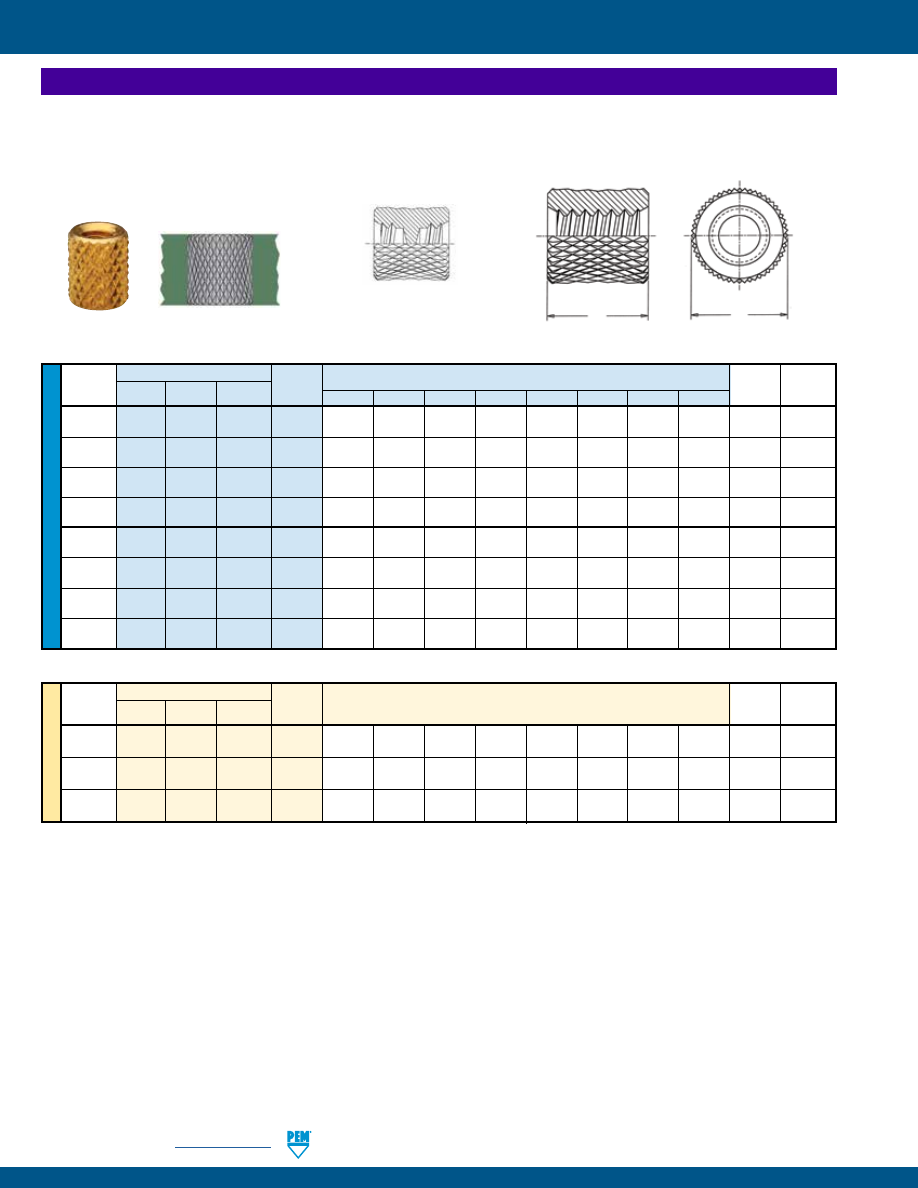
SI-12
PennEngineering •
www.pemnet.com
SI® INSERTS FOR PLASTICS
ME
TR
IC
U
NIF
IE
D
Thru-Threaded, Knurled, STKA™, STKB™ and STKC™ Inserts
•
Uniform knurl diameter reduces the risk of sink marks.
•
Available in varying lengths for injection molding assemblies.
•
Aluminum inserts ideal for light weight designs.
•
Aluminum and stainless steel inserts offer lead-free alternative.
Type
Thread
Length Code “L” ± .005
Minor
Thread
New
Brass
Stainless
Code
in 32nds of an Inch E Dia.
Size
Aluminum Steel
(1)
.125 .187 .250 .312 .375 .500 .625 .750
Nom. Min./Max.
.086-56
STKA STKB STKC 256
4
6
8
10
12
16
20
24
.156 .067/.0737
(#2-56)
.112-40
STKA STKB STKC 440
4
6
8
10
12
16
20
24
.188 .086/.0939
(#4-40)
.138-32
STKA STKB STKC 632 4
6
8
10 12 16 20 24 .219 .105/.114
(#6-32)
.164-32
STKA STKB STKC 832 4
6
8
10 12 16 20 24 .250 .131/.139
(#8-32)
.190-32
STKA STKB STKC 032 4
6
8
10 12 16 20 24 .281 .157/.164
(#10-32)
.250-20
STKA
STKB STKC 0420 4
6
8
10
12 16 20 24 .375 .197/.207
(1/4-20)
.313-18
STKA STKB STKC 0518
4
6
8
10
12
16
20
24 .437 .254/.265
(5/16-18)
.375-16
STKA STKB STKC 0616
4
6
8
10
12
16
20 NA .500 .309/.321
(3/8-16)
Thread
Type
Thread
Length Code “L” ±0.13
Minor
Size x
New
Brass
Stainless
Code
in millimeters
E Dia.
Pitch Aluminum Steel
(1)
Nom.
Min./Max.
M3 x 0.5
STKA
STKB
STKC
M3
3
4
6
8
10
12
15
18
4.74
2.47/2.59
M4 x 0.7
STKA
STKB
STKC
M4
3
4
6
8
10
12
15
18
6.35
3.25/3.42
M5 x 0.8
STKA
STKB
STKC
M5
3
4
6
8
10
12
15
18
7.13
4.15/4.34
L
E
Stock Diameter
(Before Knurl)
Configuration for
STKA/STKB/STKC-256-20 and -24
All dimensions are in inches.
All dimensions are in millimeters.
(1) Thread tapped thru, Class 3A/4h screw must pass with finger torque, but basic go gauge may stop at last thread.
NA Not Available.
MOLDED-IN INSERTS
pem-html.html
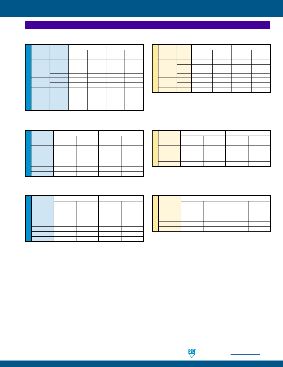
PennEngineering •
www.pemnet.com
SI-13
SI® INSERTS FOR PLASTICS
ME
TR
IC
ME
TR
IC
ME
TR
IC
U
NIF
IE
D
U
NIF
IE
D
U
NIF
IE
D
IBA, IBB and IBC Inserts
(1)
ABS Polycarbonate
Thread
Length
Pullout Torque-out Pullout Torque-out
Code
Code
(lbs.)
(in. lbs.)
(lbs.)
(in. lbs.)
256
6
148 / 140
5.8 / 5.5
165 / 158
6.2 / 5.8
10
150 / 143
6 / 5.7
167 / 160
6.4 / 5.9
440
6
250 / 240
6.2 / 5.7
265 / 253
6.9 / 6.5
10
252 / 243
6.4 / 5.9
268 / 262
7 / 6.6
632
6
425 / 415
8.5 / 8
455 / 440
9.2 / 8.7
10
428 / 420
8.6 / 8.2
458 / 452
9.3 / 8.8
832
6
530 / 521
15 / 14.1
545 / 536
16.1 / 15.4
10
533 / 526
15.8 / 15
547 / 540
16.4 / 15.8
032
6
635 / 624
57 / 52
648 / 640
59 / 56
10
637 / 629
58 / 54
651 / 646
60 / 57
0420
6
910 / 895
108 / 103
928 / 912
111 / 107
IBLC Inserts
(1)
ABS Polycarbonate
Thread Pullout Torque-out Pullout Torque-out
Code
(lbs.)
(in. lbs.)
(lbs.)
(in. lbs.)
256
128 / 118
5 / 4.6
142 / 134
5.8 / 5
440
230 / 220
6 / 5.5
238 / 226
6.8 / 6.2
632
392 / 378
7.8 / 7
406 / 390
9 / 8.2
832
496 / 480
11 / 9
500 / 468
14 / 13
032
592 / 580
40 / 30
592 / 564
48 / 42
0420
760 / 738
90 / 78
798 / 780
99 / 84
ABS Polycarbonate
Thread Pullout Torque-out Pullout Torque-out
Code
(N) (N•m) (N) (N•m)
M3
1020 / 970
0.67 / 0.62
1050 / 1000
0.76 / 0.7
M4
2200 / 2130
1.24 / 1.01
2220 / 2080
1.58 / 1.46
M5
2630 / 2570
4.52 / 3.39
2630 / 2500
5.42 / 4.74
M6
3380 / 3280
10.1 / 8.81
3540 / 3460
11.1 / 9.49
ABS Polycarbonate
Thread Pullout Torque-out Pullout Torque-out
Code
(N) (N•m) (N) (N•m)
M3
770 / 730
0.67 / 0.62
820 / 760
0.77 / 0.7
M4
1640 / 1630
1.58 / 1.53
1690 / 1650
1.8 / 1.66
M5
1970 / 1920
6.22 / 5.65
2010 / 1970
6.44 / 5.87
M6
2820 / 2750
8.47 / 7.91
2890 / 2820
11.6 / 11
ITA, ITB and ITC Inserts
(1)
ABS Polycarbonate
Thread Pullout Torque-out Pullout Torque-out
Code
(lbs.)
(in. lbs.)
(lbs.)
(in. lbs.)
080/256
104 / 96
5.6 / 5.2
115 / 106
6 / 5.6
440
175 / 166
6 / 5.5
186 / 173
6.9 / 6.2
632
298 / 290
8 / 7.5
318 / 302
9 / 8.5
832
370 / 368
14 / 13.6
382 / 372
16 / 14.7
032
444 / 432
55 / 50
454 / 445
57 / 52
0420/0428
635 / 620
75 / 70
650 / 635
103 / 98
(1) The values reported are high and low ranges when all installation specifications and procedures are followed. Variations in mounting hole size,
workpiece material and installation procedure will affect results. Performance testing of this product in your application is recommended. Samples can
be provided for this purpose.
ABS Polycarbonate
Thread Length
Pullout Torque-out Pullout Torque-out
Code
Code
(N)
(N•m)
(N)
(N•m)
M2.5/M3
6
1110 / 1060
0.7 / 0.64
1170 / 1120
0.77 / 0.73
10
1120 / 1080
0.72 / 0.66
1190 / 1160
0.79 / 0.74
M4
6
2350 / 2310
1.69 / 1.59
2420 / 2380
1.81 / 1.74
10
2370 / 2330
1.78 / 1.69
2430 / 2400
1.85 / 1.79
M5
6
2820 / 2770
6.44 / 5.87
2880 / 2840
6.66 / 6.32
10
2830 / 2790
6.55 / 6.1
2890 / 2870
6.78 / 6.44
M6
6
4040 / 3980
12.2 / 11.6
4120 / 4050
12.5 / 12
PERFORMANCE DATA FOR MOLDED-IN INSERTS
pem-html.html
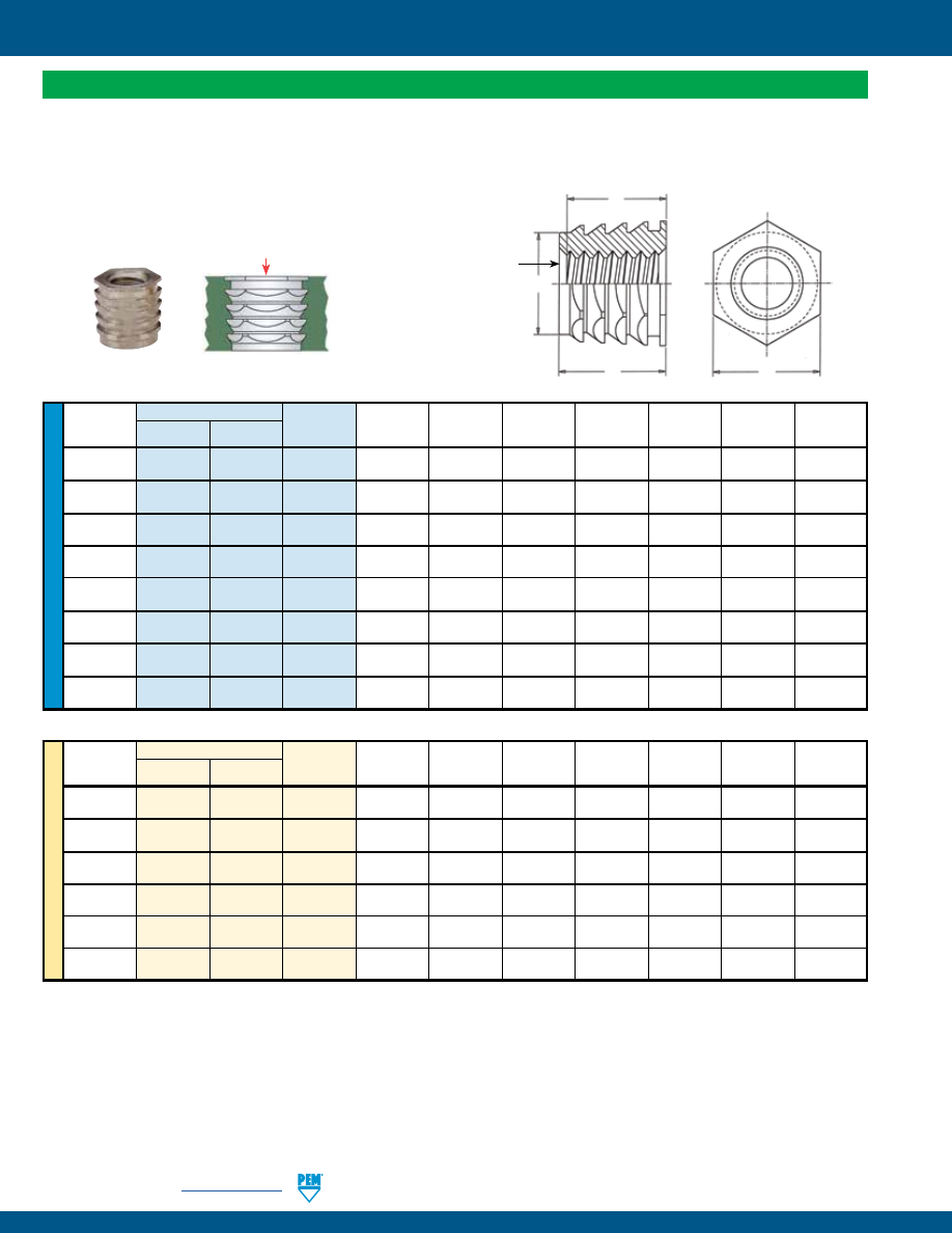
SI-14
PennEngineering •
www.pemnet.com
SI® INSERTS FOR PLASTICS
ME
TR
IC
U
NIF
IE
D
Hexagonal, NFPA™ and NFPC™ Inserts
•
Press-fit insert provides strong, reusable threads. No heat or ultrasonics required.
•
Hexagonal “barbed” configuration ensures high torque-out and pullout values.
•
Aluminum inserts ideal for light weight designs.
•
Aluminum and stainless steel inserts offer lead-free alternative.
Type
Min.
Hole Size
Min.
Min. Depth
Thread
Aluminum
Stainless
Thread A
Sheet
in Sheet
C E
Boss
Full Thread
Size Steel
Code Max.
Thickness
+ .003 - .000
Max. Nom. Dia. H
(1)
.086-56
NFPA NFPC 256 .230 .240 .187 .186 .187 .500 .212
(#2-56)
.112-40
NFPA NFPC 440 .230 .240 .187 .186 .187 .500 .212
(#4-40)
.138-32
NFPA NFPC 632 .230 .240 .187 .186 .187 .500 .212
(#6-32)
.164-32
NFPA NFPC 832 .265 .275 .250 .249 .250 .625 .248
(#8-32)
.190-24
NFPA NFPC 024 .265 .275 .250 .249 .250 .625 .248
(#10-24)
.190-32
NFPA NFPC 032 .265 .275 .250 .249 .250 .625 .248
(#10-32)
.250-20
NFPA NFPC 0420 .315 .328 .312 .311 .312 .750 .300
(1/4-20)
.313-18
NFPA NFPC 0518 .365 .380 .375 .374 .375 .950 .345
(5/16-18)
Thread
Type
Min.
Hole Size
Min.
Min. Depth
Size x
Aluminum
Stainless
Thread A
Sheet
in Sheet
C E
Boss
Full Thread
Pitch
Steel
Code Max.
Thickness
+ 0.08
Max. Nom. Dia. H
(1)
M3 x 0.5
NFPA
NFPC
M3
5.84
6.1
4.75
4.72
4.75
12.7
5.38
M3.5 x 0.6
NFPA
NFPC
M3.5
5.84
6.1
4.75
4.72
4.75
12.7
5.38
M4 x 0.7
NFPA
NFPC
M4
6.73
6.99
6.35
6.32
6.35
15.88
6.3
M5 x 0.8
NFPA
NFPC
M5
6.73
6.99
6.35
6.32
6.35
15.88
6.3
M6 x 1
NFPA
NFPC
M6
8
8.33
7.92
7.89
7.92
19.05
7.62
M8 x 1.25
NFPA
NFPC
M8
9.27
9.65
9.53
9.50
9.53
24.13
8.76
(1) Thread tapped thru, Class 3A/4h screw must pass with finger torque, but basic go gauge may stop at pilot end.
H
C
Pilot
End
A
E
All dimensions are in inches.
All dimensions are in millimeters.
Install
PRESS-IN INSERTS
pem-html.html
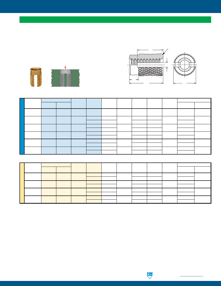
PennEngineering •
www.pemnet.com
SI-15
SI® INSERTS FOR PLASTICS
ME
TR
IC
U
NIF
IE
D
Thru-Threaded, PPA™ and PPB™ Inserts
•
Press-fit insert with strong, reusable threads.
No heat or ultrasonics required.
•
Slotted insert compresses allowing easy access into the mounting hole.
•
Aluminum inserts ideal for light weight designs.
•
Aluminum inserts offer lead-free alternative.
Type
Thread
E
Hole Size in Material
Thread
New
Code Length A
Nom.
B S W
Min. Hole
Hole Dia.
Size
Aluminum
Brass
(1)
Code
± .005 ± .015
Nom.
± .015
Depth
± .002
.086-56
PPA PPB 256 1 .156 .125 .040 .115 .020 .196 .125
(#2-56)
.112-40
PPA PPB 440 1 .188 .156 .045 .140 .020 .228 .156
(#4-40)
2
.250
.060
.190
.290
.138-32
PPA PPB 632 1 .250 .188 .060 .190 .031 .290 .188
(#6-32)
2
.313
.075
.235
.353
.164-32
PPA PPB 832 1 .250 .219 .060 .190 .047 .290 .219
(#8-32)
2
.313
.075
.235
.353
.190-32
PPA PPB 032 1 .313 .250 .075 .235 .062 .353 .250
(#10-32)
2
.375
.090
.280
.415
.250-20
PPA PPB 0420 1 .438 .313 .105 .330 .078 .478 .313
(1/4-20)
2
.500
.120
.375
.540
Thread Type
Thread
E
Hole Size in Material
Size x
New
Code Length A
Nom.
B S W
Min. Hole
Hole Dia.
Pitch
Aluminum
Brass
(1)
Code
± 0.13 ± 0.4
Nom.
± 0.4
Depth
± 0.05
M3 x 0.5
PPA
PPB
M3 1 4.77 3.96 1.14 3.56 0.5 5.79 3.96
2
6.35
1.52
4.83
7.37
M4 x 0.7
PPA
PPB
M4 1 6.35 5.56 1.52 4.83 1.2 7.37 5.56
2
7.95
1.91
5.97
8.97
M5 x 0.8
PPA
PPB
M5 1 7.95 6.35 1.91 5.97 1.6 8.97 6.35
2
9.52
2.29
7.11
10.54
M6 x 1
PPA
PPB
M6 1 11.12 7.95 2.67 8.38 2 12.14 7.95
2
12.7
3.05
9.53
13.72
S
20° Chamfer
Stock Diameter
(Before Knurl)
W
A
E
B
All dimensions are in inches.
All dimensions are in millimeters.
(1) Collapsed slot and burrs may cause prevailing torque while thread accepts class 3A/4h screw.
Install
PRESS-IN INSERTS
pem-html.html
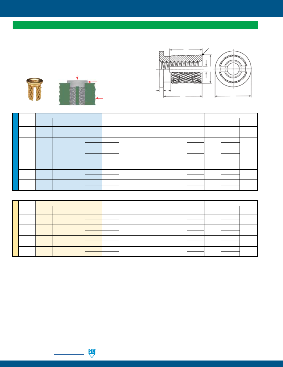
SI-16
PennEngineering •
www.pemnet.com
SI® INSERTS FOR PLASTICS
ME
TR
IC
U
NIF
IE
D
Type
Thread
Hole Size in Material
Thread
New
Code Length A
E
C
T
B
S W
Min. Hole
Hole Dia.
Size
Aluminum
Brass
(1)
Code
± .005
Nom.
Nom.
± .005
± .010
Nom.
± .015
Depth
± .002
.086-56
PFLA PFLB 256 1 .136 .188 .135 .020 .025 .115 .020 .176 .125
(#2-56)
.112-40
PFLA PFLB 440
1 .166
.219 .166 .022 .027
.140
.020
.206
.156
(#4-40)
2 .228
.190 .268
.138-32
PFLA PFLB 632
1 .222
.250 .200 .028 .033
.190
.031
.262
.188
(#6-32)
2 .253
.210 .293
.164-32
PFLA PFLB 832
1 .246
.281 .230 .035 .040
.210
.047
.286
.219
(#8-32)
2 .278 .235 .318
.190-32
PFLA PFLB 032
1 .270
.313 .262 .043 .048
.235
.062
.310
.250
(#10-32)
2 .332 .280 .372
.250-20
PFLA PFLB 0420
1 .388
.375 .335 .050 .055
.330
.078
.428
.313
(1/4-20)
2 .450 .375 .490
Flange-Head, PFLA™ and PFLB™ Inserts
•
Press-fit insert with strong, reusable threads. No heat or ultrasonics required.
•
Flange-head eliminates direct contact of plastic with mating parts.
•
Slotted insert compresses allowing easy access into the mounting hole.
•
Aluminum inserts ideal for light weight designs.
•
Aluminum inserts offer lead-free alternative.
Thread Type
Thread
Hole Size in Material
Size x
New
Code Length A
E
C
T
B
S W
Min. Hole
Hole Dia.
Pitch Aluminum
Brass
(1)
Code
± 0.13
Nom.
Nom.
± 0.13
± 0.25
Nom.
± 0.4
Depth
± 0.05
M3 x 0.5
PFLA
PFLB
M3
1 4.22
5.56 4.22 0.56 0.69
3.56
0.5
5.24
3.96
2
5.8
4.83
6.82
M4 x 0.7
PFLA
PFLB
M4
1 6.25
7.14 5.84 0.89 1.02
5.33
1.14
7.27
5.56
2
7.06
5.97
8.08
M5 x 0.8
PFLA
PFLB
M5
1 6.86
7.95 6.65 1.09 1.22
5.97
1.6
7.88
6.35
2
8.43 7.11 9.45
M6 x 1
PFLA
PFLB
M6
1 9.86
9.53 8.51 1.27 1.40
8.38
2
10.88
7.95
2
11.43
9.53
12.45
All dimensions are in inches.
All dimensions are in millimeters.
T
B
W
A
S
E
*C Diameter (After Knurl)
C*
20° Chamfer
(1) Collapsed slot and burrs may cause prevailing torque while thread accepts class 3A/4h screw.
Sheet
When flange head of the
insert contacts the sheet,
insert is fully installed.
Install
PRESS-IN INSERTS
pem-html.html
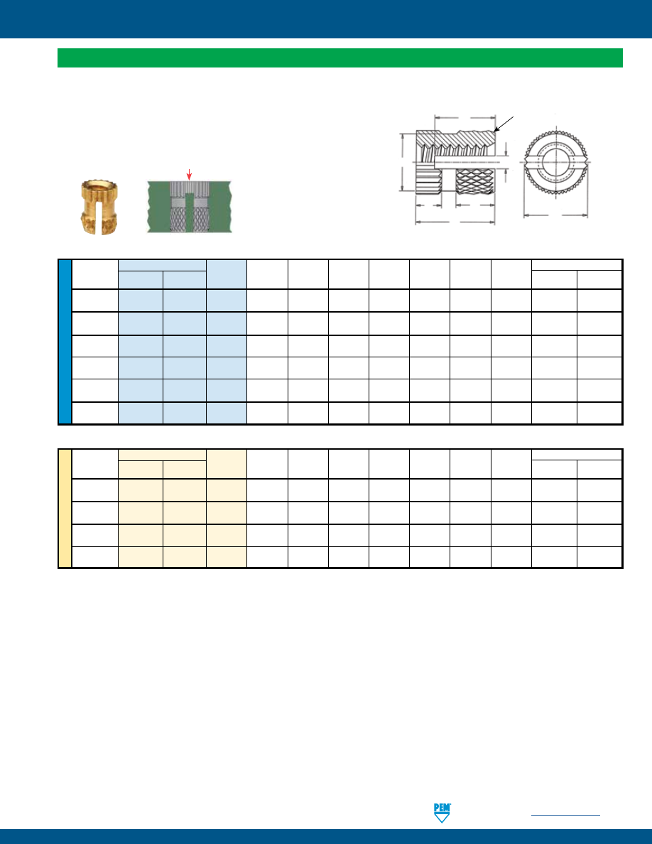
PennEngineering •
www.pemnet.com
SI-17
SI® INSERTS FOR PLASTICS
ME
TR
IC
U
NIF
IE
D
Type
Thread
Hole Size in Material
Thread
New
Code A E
C
B
1
B
2
S W
Min. Hole
Hole Dia.
Size
Aluminum Brass
(1)
± .005
Nom.
± .010
± .010
± .010
Nom.
± .015
Depth
± .002
.086-56
PKA PKB 256 .125 .125 .110 .037 .053 .095 .020 .165 .125
(#2-56)
.112-40
PKA PKB 440 .188 .156 .137 .056 .079 .140 .020 .228 .156
(#4-40)
.138-32
PKA PKB 632 .250 .188 .165 .075 .105 .190 .031 .290 .188
(#6-32)
.164-32
PKA PKB 832 .312 .219 .196 .094 .131 .235 .047 .352 .219
(#8-32)
.190-32
PKA PKB 032 .375 .250 .234 .112 .158 .280 .062 .415 .250
(#10-32)
.250-20
PKA PKB 0420 .500 .312 .291 .150 .210 .375 .078 .540 .312
(1/4-20)
All dimensions are in inches.
Thread Type
Thread
Hole Size in Material
Size x
New
Code A E
C
B
1
B
2
S W
Min. Hole
Hole Dia.
Pitch Aluminum Brass
(1)
± 0.13
Nom.
± 0.25
± 0.25
± 0.25
Nom.
± 0.4
Depth
± 0.05
M3 x 0.5
PKA
PKB
M3
4.78
3.96
3.48
1.42
2.01
3.56
0.5
5.8
3.96
M4 x 0.7
PKA
PKB
M4
7.92
5.56
4.98
2.39
3.33
5.97
1.19
8.94
5.56
M5 x 0.8
PKA
PKB
M5
9.53
6.35
5.94
2.84
4.01
7.11
1.57
10.55
6.35
M6 x 1
PKA
PKB
M6
12.7
7.92
7.39
3.81
5.33
9.53
1.98
13.72
7.92
All dimensions are in millimeters.
A
C
E
S
B
1
B
2
W
20° Chamfer
Stock Diameter
(Before Knurl)
Straight Knurl, PKA™ and PKB™ Inserts
•
Press-fit insert with strong, reusable threads. No heat or ultrasonics required.
•
Straight knurls at the top end of the insert offers higher torsional resistance.
•
Slotted insert compresses allowing easy access into the mounting hole.
•
Aluminum inserts ideal for light weight designs.
•
Aluminum inserts offer lead-free alternative.
(1) Collapsed slot and burrs may cause prevailing torque while thread accepts class 3A/4h screw.
Install
PRESS-IN INSERTS
pem-html.html
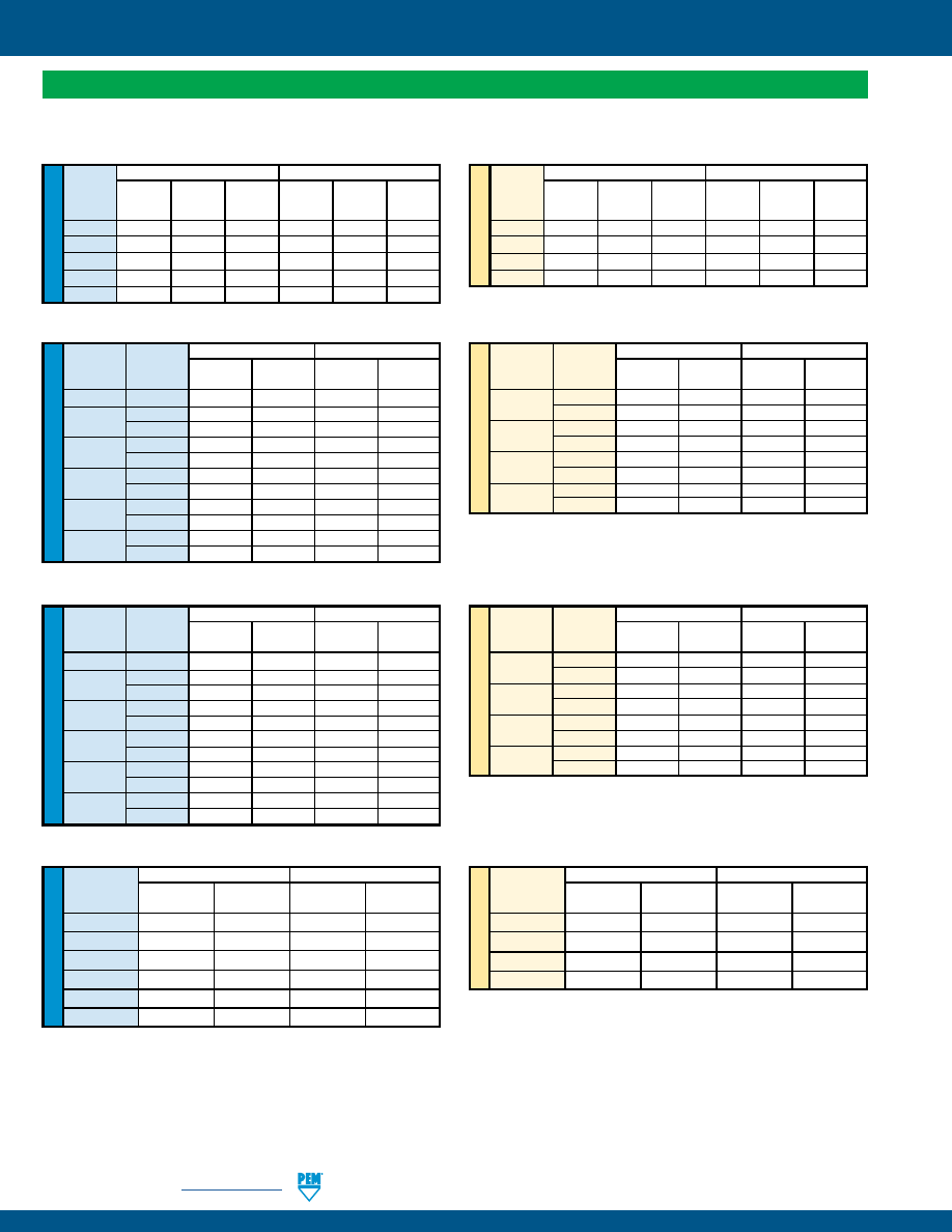
SI-18
PennEngineering •
www.pemnet.com
SI® INSERTS FOR PLASTICS
ME
TR
IC
ME
TR
IC
ME
TR
IC
ME
TR
IC
U
NIF
IE
D
U
NIF
IE
D
U
NIF
IE
D
U
NIF
IE
D
NFPA and NFPC Inserts
(1)
ABS
Polycarbonate
Thread Install.
Pullout Torque-out
Install.
Pullout Torque-out
Code
Force
(lbs.)
(in. lbs.)
Force
(lbs.)
(in. lbs.)
(lbs.)
(lbs.)
440
225
125
4
600
280
16
632 225 125 4 600 280 16
832
300
135
10
600
380
42
032
300
135
10
600
380
42
0420 400 235 28 – –
–
(1) The values reported are averages when all installation specifications and procedures are followed. Variations in mounting hole size, work piece material
and installation procedure will affect results. Performance testing of this product in your application is recommended. Samples can be provided for this
purpose.
ABS
Polycarbonate
Thread Install.
Pullout Torque-out
Install.
Pullout Torque-out
Code
Force
(N)
(N • m)
Force
(N)
(N • m)
(kN)
(kN)
M3
1
556
0.45
2.67
1245
1.8
M4
1.33
600
1.13
2.67
1690
4.74
M5
1.33
600
1.13
2.67
1690
4.74
M6
1.78
1045
3.16
–
–
–
PPA and PPB Inserts
(1)
Phenolic Polycarbonate
Thread
Length
Pullout Torque-out Pullout Torque-out
Code
Code
(lbs.)
(in. lbs.)
(lbs.)
(in. lbs.)
256
1
60
12.8
52
7.2
440 1 81 20.8 74 15.3
2
193
38.6
170
25.2
632 1 104 29.2 94 23.4
2
221
49.6
198
35.6
832 1 126 36.8 116 31.6
2
249
59.8
224
45.6
032 1 147 45.0 138 39.6
2
276
69.6
253
55.6
0420 1 192 61.6 182 56.0
2
334
91.2
308
76.6
Phenolic Polycarbonate
Thread
Length
Pullout Torque-out Pullout Torque-out
Code
Code
(N)
(N • m)
(N)
(N • m)
M3 1 360 2.35 330 1.73
2
860
4.36
760
2.85
M4 1 560 4.16 520 3.57
2
1110
6.76
1000
5.15
M5 1 650 5.09 610 4.47
2
1230
7.86
1130
6.28
M6 1 850 6.96 810 6.33
2
1490
10.31
1370 8.66
PFLA and PFLB Inserts
(1)
Phenolic Polycarbonate
Thread
Length
Pullout Torque-out Pullout Torque-out
Code
Code
(lbs.)
(in. lbs.)
(lbs.)
(in. lbs.)
256
1
28
8.0
17
8.0
440 1 40 14.7 28 14.7
2
64
14.7
44
14.7
632 1 53 22.0 41 22.0
2
77
22.0
56
22.0
832 1 64 28.8 53 28.8
2
72
28.8
68
28.8
032 1 76 35.6 65 35.6
2
100
35.6
80
35.6
0420 1 100 49.8 89 49.8
2
125
49.8
104
49.8
PKA and PKB Inserts
(1)
Phenolic Polycarbonate
Thread
Pullout Torque-out Pullout Torque-out
Code
(lbs.) (in.
lbs.) (lbs.) (in.
lbs.)
256
22
13.2
11
5.2
440
42
22.2
32
14.4
632
64
32.6
53
24.6
832
84
42.0
73
33.8
032
106
51.2
94
43.0
0420
149
71.0
136
62.0
Phenolic Polycarbonate
Thread
Length
Pullout Torque-out Pullout Torque-out
Code
Code
(N)
(N • m)
(N)
(N • m)
M3 1 180 1.66 130 1.66
2
280
1.66
200
1.66
M4 1 280 3.25 240 3.25
2
320
3.25
300
3.25
M5 1 340 4.02 290 4.02
2
450
4.02
360
4.02
M6 1 450 5.63 400 5.63
2
560
5.63
460
5.63
Phenolic Polycarbonate
Thread
Pullout Torque-out Pullout Torque-out
Code
(N)
(N • m)
(N)
(N • m)
M3
190
2.51
140
1.63
M4
370
4.75
320
3.82
M5
470
5.79
420
4.86
M6
660
8.02
610
7.01
PERFORMANCE DATA FOR PRESS-IN INSERTS
pem-html.html
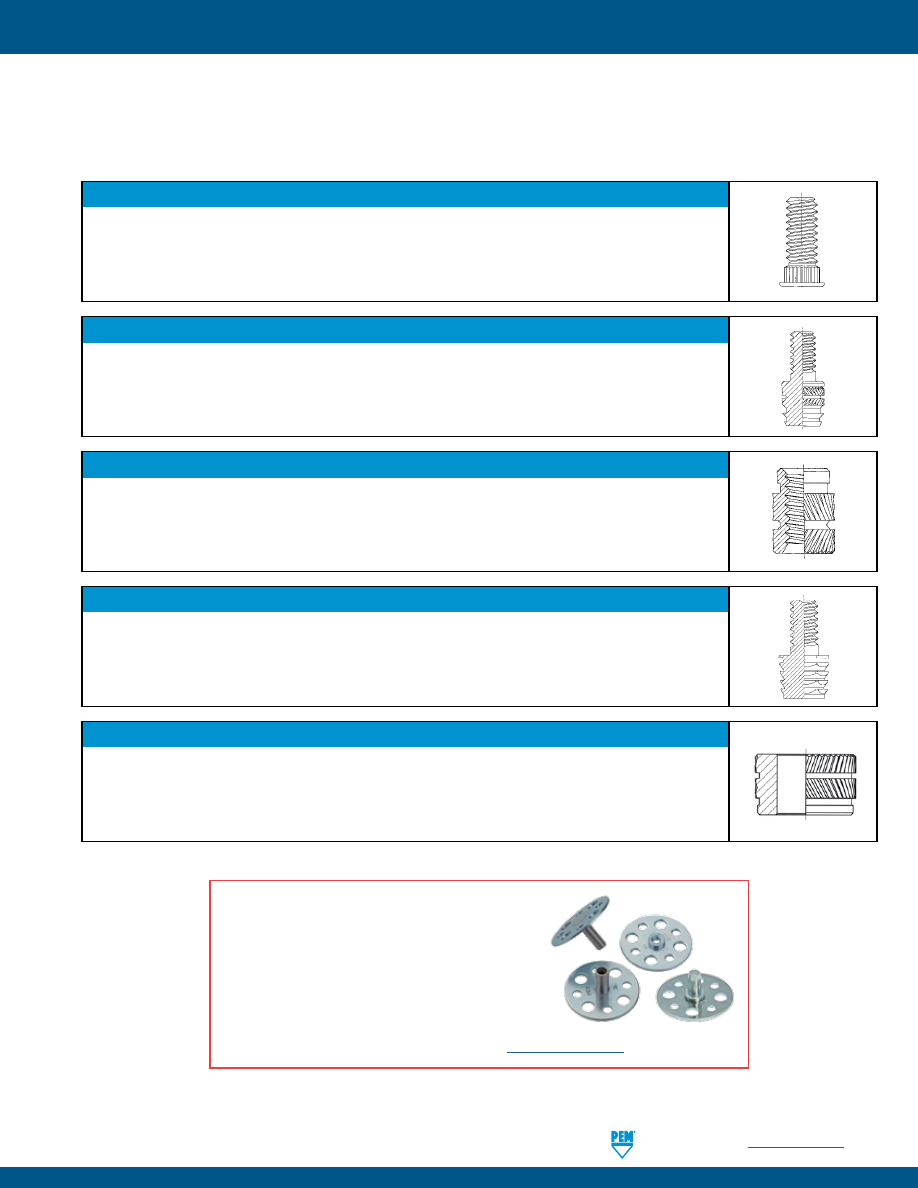
PennEngineering •
www.pemnet.com
SI-19
SI® INSERTS FOR PLASTICS
If you can not find a standard product in this catalog to meet your requirements, our Application Engineering Department
will assist you to design a custom fastener to satisfy your requirements. Below are a few examples of custom insert designs.
THIN SHEET STUDS
Provide external threads in material as thin as .125” / 3.175 mm. SI® studs are available in lengths
from 1/4” to 3/4” / 6.35 to 19.05 mm in thread sizes #4-40 to 1/4-20 / M3 to M6. These inserts
can be provided in aluminum, brass, steel and stainless steel and can be pressed into pre-
molded or drilled holes.
ULTRASONIC STUDS
Tapered body provides easy insertion in pre-molded or drilled holes. They are available in
lengths from 1/4” to 3/4” / 6.35 to 19.05 mm in thread sizes #2-56 to 1/4-20 / M2 to M6. These
inserts can be provided in aluminum, brass, steel and stainless steel.
SELF-LOCKING ULTRASONIC INSERTS
The self-locking feature prevents screw loosening and is advantageous in applications where
vibration is present. They are available in thread sizes #2-56 to 1/4-20 / M2 to M6 and are
designed for ultrasonic installation into straight or tapered holes.
PRESS-IN STUDS
Allows for mounting a component on the external thread. They are available in lengths from
3/16” to 1” / 4.76 to 25.4 mm. Thread sizes #4-40 to 1/4-20 / M3 to M6. SI® press-in studs can
be provided in aluminum, brass, steel and stainless steel and can be installed into pre-molded
or drilled holes without the use of heat or ultrasonics.
PEM® VARIMOUNT® BONDING FASTENERS
•
Laminate within composite layers.
•
Mold into plastics.
•
Surface bond to panels from front or back side.
•
Available with studs, nuts, or standoffs to meet a
variety of applications.
For more information, see
PEM® Bulletin VM
.
COMPRESSION LIMITER
Thru-hole metal insert designed for use in plastic components. It provides bolt clearance,
while the wall of the compression limiter withstands the compressive force induced during the
assembly of the mating screw or bolt.
pem-html.html
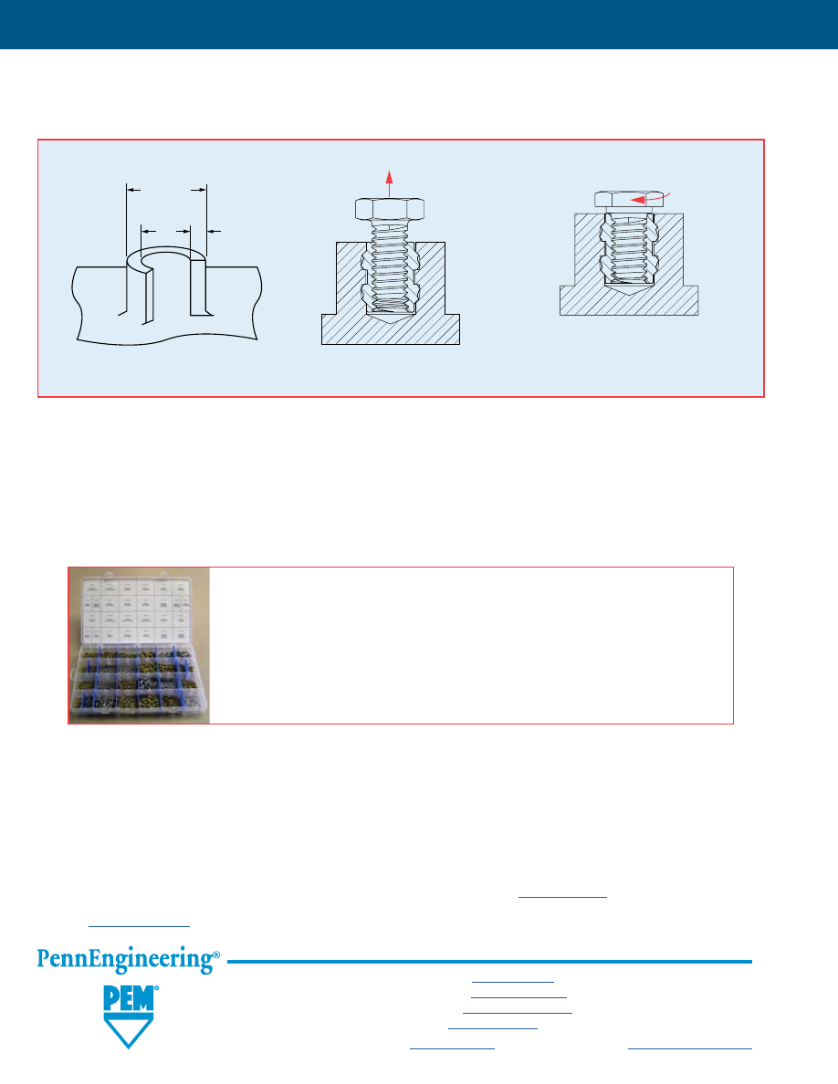
The SI® prototype kit contains a wide variety of SI® threaded inserts for plastics for your
prototype needs. The kit contains over 1,000 ultrasonic, molded-in, and press-in inserts of
various types and sizes, so you can choose the one which will best suit your specific design
requirements. The kit contains both unified and metric parts.
PEM Part #PKSI-100. Price - US $50.00 (Subject to change without notice).
All specifications in this bulletin are presented as accurately and up-to-date as possible. We reserve the right to make changes to any information
contained in this bulletin without notice.
We recommended that you test a particular product to be sure it is ideally suited to your application. We will be happy to provide samples for this
purpose and our authorized distributors can also help you with your selection.
Pullout
is the force required to
pull the insert from the sheet.
PULLOUT
Torque-out
is the torque required to
turn the fastener in the parent material
after installation without inducing
clamp load on the fastener.
TORQUE OUT
Thinner walls and bosses may be
used but will affect performance.
HOLE PREPARATION GUIDELINES
Wall Thickness
Boss Dia.
2 x Insert Dia.
Insert
Dia.
SI® INSERTS FOR PLASTICS
SI-20
All PEM® products meet our stringent quality standards. If you require additional industry or other specific
quality certifications
, special procedures and/or part
numbers are required. Please contact your local sales office or representative for further information.
Regulatory
compliance information
is available in Technical Support section of our website. Specifications subject to change without notice. See our website for the
most current version of this bulletin.
North America:
Danboro, Pennsylvania USA
•
E-mail:
info@pemnet.com
•
Tel: +1-215-766-8853
•
800-237-4736 (USA)
Europe:
Galway, Ireland
•
E-mail:
europe@pemnet.com
•
Tel: +353-91-751714
Asia/Pacific:
Singapore
•
E-mail:
singapore@pemnet.com
•
Tel: +65-6-745-0660
Shanghai, China
•
E-mail:
china@pemnet.com
•
Tel: +86-21-5868-3688
Visit our PEMNET™ Resource Center at
www.pemnet.com
•
Technical support e-mail:
techsupport@pemnet.com