SK
™
SELF-CLINCHING
KEYHOLE® FASTENERS
PEM® KEYHOLE® fasteners are
designed for quick panel attachment
and reduction of loose hardware.
H
N
C
B
A
S
M
SK
™
SELF-CLINCHING
KEYHOLE® FASTENERS
PEM® KEYHOLE® fasteners are
designed for quick panel attachment
and reduction of loose hardware.
H
N
C
B
A
S
M
Keyhole® Standoffs And Fasteners
SK-2
PennEngineering •
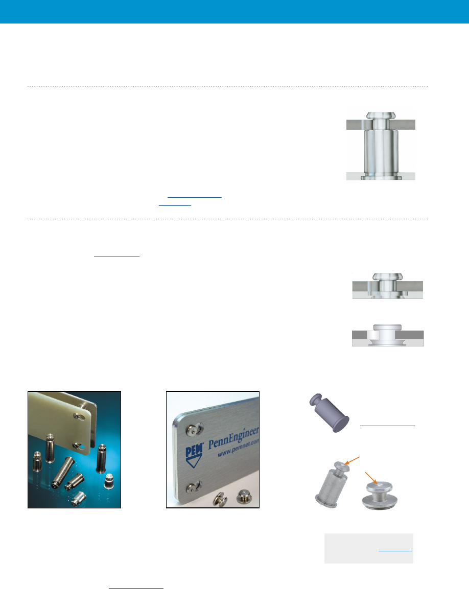
PEM® KEYHOLE® Standoffs and sheet joining fasteners are designed so that a PC board or panel can be quickly slipped into place
and then removed from an assembly by simply sliding the board sideways and lifting it off. These standoffs and fasteners can save
valuable time and dramatically reduce the amount of loose hardware required.
SKC™/SK4™/SKCF™/SK4F™/
SKSF™ standoffs
SKC-F™/SK4-F™/SKS-R™/HSKC-R™/
HSK4-R™/HSKS-R™/TSKC-R™/
TSK4-R™/TSKS-R™ fasteners
© 2023 PennEngineering.
Drawings and models
are available at
PEM® Dimple
(Registered Trademark)
SKC-F™/SK4-F™/SKS-R™/HSKC-R™/HSK4-R™/HSKS-R™/TSKC-R™/TSK4-R™/TSKS-R™ fasteners
are designed
so that two sheets can be quickly joined flat against each other. Typically, several fasteners are used with one standard PEM®
threaded F™ flush nut (
) which accepts a screw to secure the sheets against any unwanted movement.
• Allow detachable spacing of two sheets
• Clinch feature mounts fastener permanently and flush or sub-flush into metal sheet
• Unique barrel design allows for quick “panel-on-panel” attachment and detachment
• Can be clinched into blind hole where concealed head is required
• Makes horizontal or vertical component mounting possible
• SK4-R™, HSK4-R™, TSK4-R™, SK4-F™, SK4F-F™ and TSK4F-F™ fasteners are available for
installation into stainless steel sheets
• SKS-R™, SKC-R™, SK4-R™, TSKS-R™, HSKS-R™, TSKC-R™, TSK4-R™, HSKC-R™ and
HSK4-R™ fasteners are designed to provide high side-load in vertical component
mounting applications and are available for various top sheet thicknesses and hole sizes
SKC™/SK4™/SKCF™/SK4F™/SKSF™ standoffs
can be used for spacing or mounting of
replaceable components. Typically, several standoffs are used with one standard PEM® threaded
standoff which accepts a screw to secure the board or component against any unwanted movement.
• Allow detachable spacing of two sheets
• Clinch feature mounts fastener permanently and flush into metal sheet
• Unique barrel design allows for quick attachment and detachment
• Makes horizontal or vertical component mounting possible
• SK4™ and SK4F™ standoffs are available for installation into stainless steel sheets
Fastener drawings and models are available at
Custom sizes are available on special order.
for more information.
SKC-F™/SK4-F™ Fasteners
SKS-R™/HSKC-R™/HSK4-R™/
HSKS-R™/TSKC-R™/TSK4-R™/
TSKS-R™ Fasteners
Custom sizes are available
on special order.
for more information.
Uni
fie
d
Me
tric
Uni
fie
d
Me
tric
Keyhole® Standoffs And Fasteners
SK-3
Type Body
Length “L” ± .005
Size -
(Length Code in 32nds of an inch)
A B C S M H
300 Series 400 Series Sheet
± .003 ± .003 Max. ± .003 Max. Nom.
Stainless Stainless Code .063 .125 .188 .250 .312 .375 .437 .500 .562 .625 .750 .875 1.00
Steel Steel
SKC
SK4 6060 2 4
6
8
10 12 14 16 18 20 24 28 32 .099 .177 .212 .068 .108 .250
Type
Body
Length “L” ± 0.13
300 Series 400 Series Size -
(Leng th Code in millimeters)
A B C S M H
Stainless Stainless
Sheet
±
0.08
±
0.08
Max.
±
0.08
Max.
Nom.
Steel (1) Steel
(2) Code
SKC
SK4 61.5 2 4
6
8
10 12
14 16
18 20 22 25 2.51 4.5 5.39 1.73 2.75 6.35
All dimensions are in inches.
All dimensions are in millimeters.
SK C – 6 060 – 12
SK 4 – 6 060 – 12
Type
Body
Size
Code
Length
Code
Material
Code
Sheet
Thickness
Code
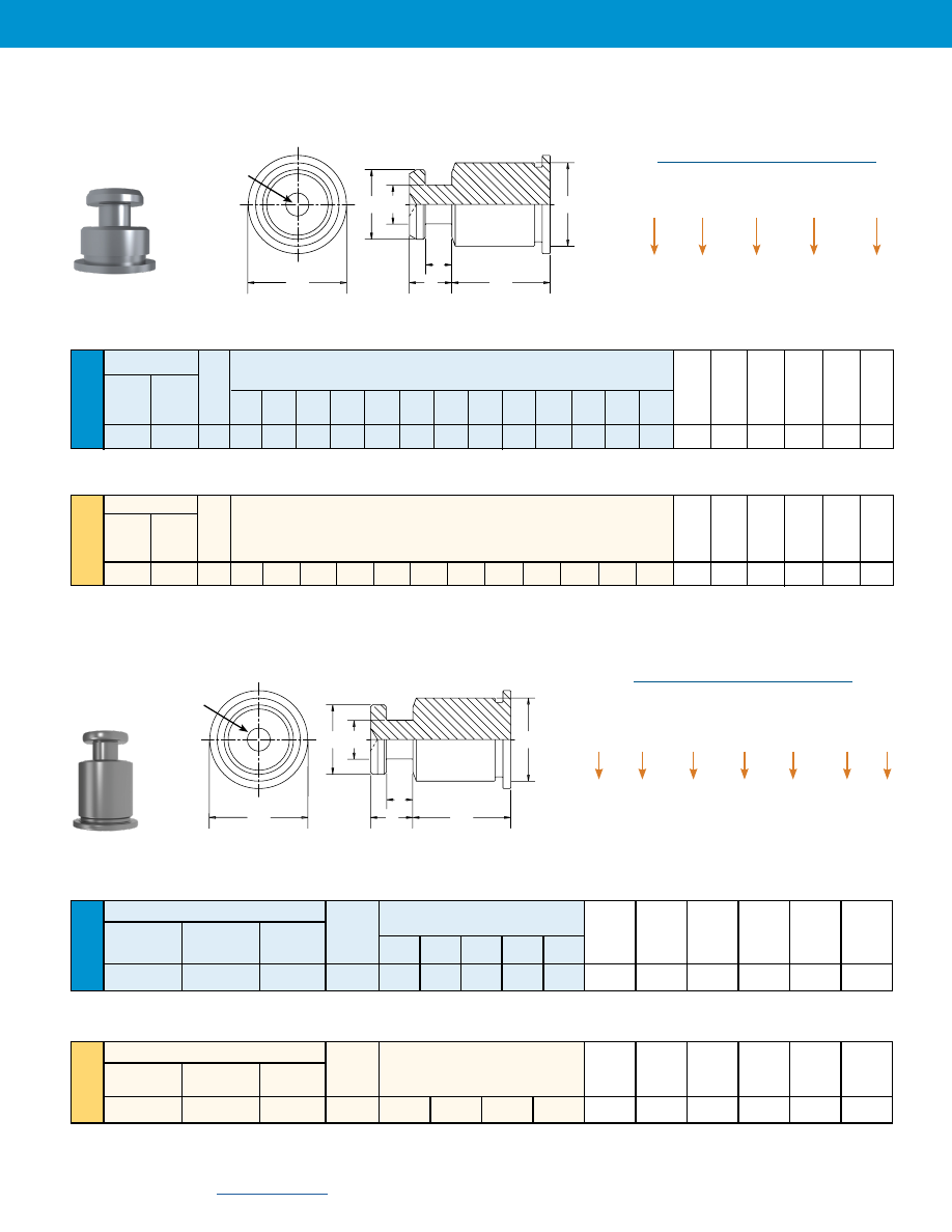
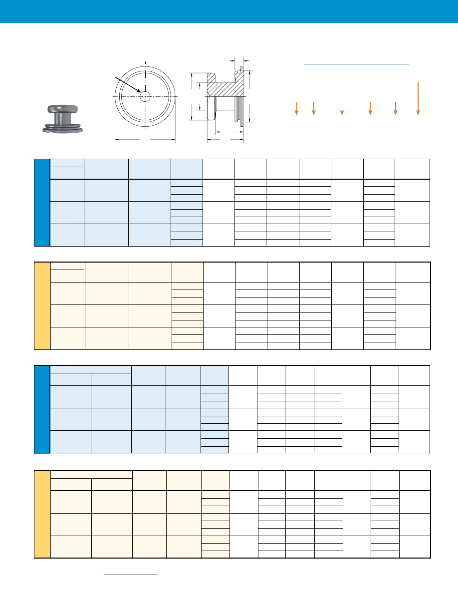
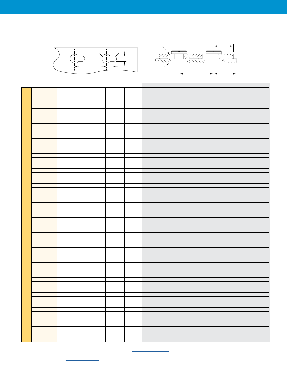
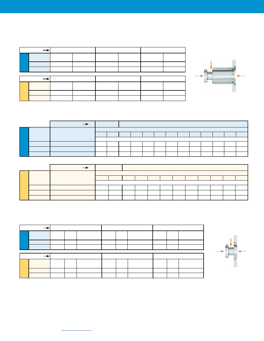
SKC™/SK4™ Standoff Dimensional Data
H
L
C
B
A
S
M
PEM “dimple”
registered
trademark.
Clinching profile may vary.
All dimensions are in inches.
Type
Body Size
Sheet
Code
Length “L” ±.005
(Length Code in 32nds of an inch)
A
±.003
B
±.003
C
Max.
S
±.003
M
Max.
H
Nom.
300 Series Stain-
less Steel
400 Series
Stainless Steel
Hardened
Steel
.125
.188
.250
.312
.375
SKCF
SK4F
SKSF
6060
4
6
8
10
12
.099
.177
.212
.068
.108
.250
Type
Body Size
Sheet
Code
Length “L” ±0.13
(Length Code in millimeters)
A
±0.08
B
±0.08
C
Max.
S
±0.08
M
Max.
H
Nom.
300 Series Stain-
less Steel
400 Series
Stainless Steel
Hardened
Steel
SKCF
SK4F
SKSF
61.5
4
6
8
10
2.51
4.5
5.39
1.73
2.75
6.35
All dimensions are in millimeters.
SK C
F - 6 060 - 8
SK 4
F - 6 060 - 8
SK S
F - 6 060 - 8 ZI
Type
Part Number Designation
Material
Code
Body Size
Code
Length
Code
Sheet
Thickness
Code
Finish
Manu-
facturing
Code
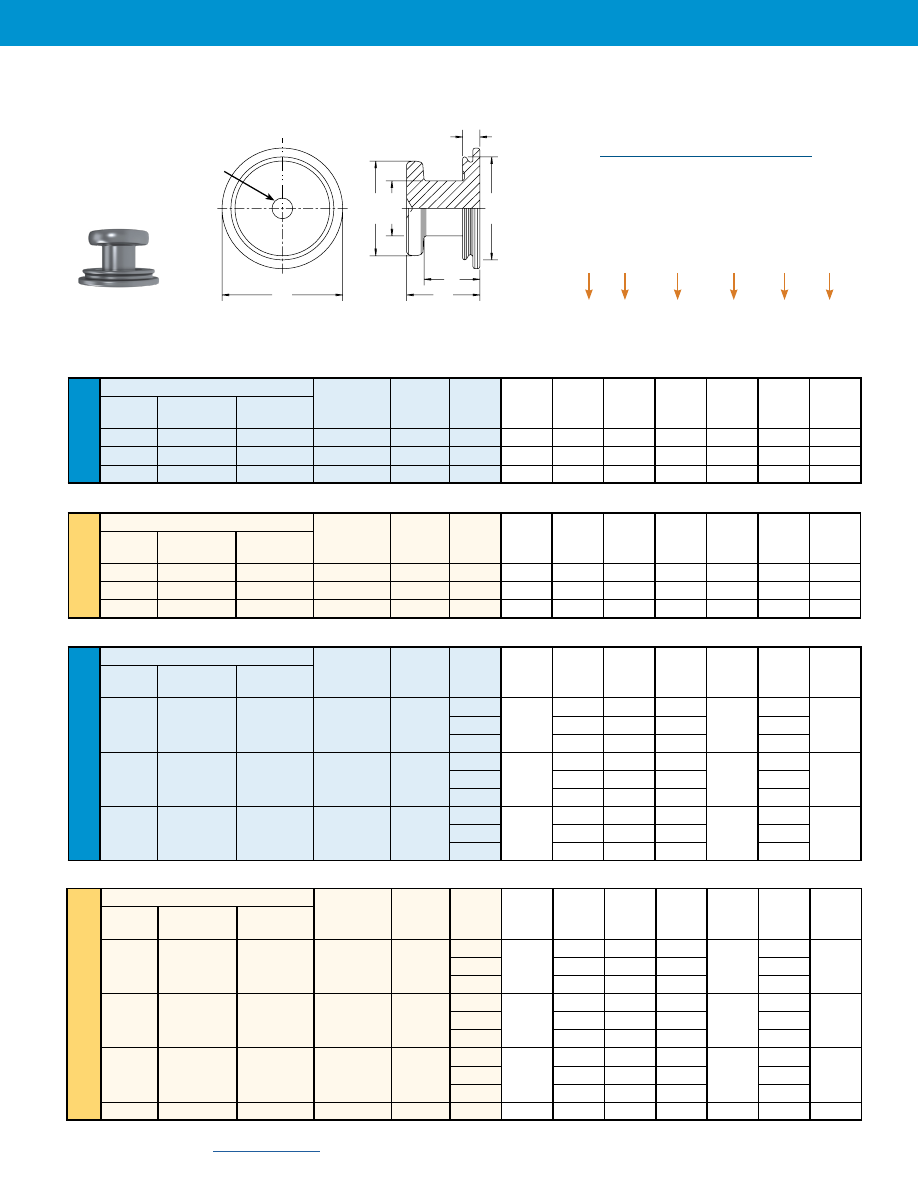
SKCF™/SK4F™/SKSF™ Standoff Dimensional Data
H
L
C
B
A
S
M
PEM “dimple”
registered
trademark.
Clinching profile may vary.
Part Number Designation
Uni
fie
d
Me
tric
Uni
fie
d
Me
tric
Keyhole® Standoffs And Fasteners
SK-4
PennEngineering •
Type
Face
Top Sheet
A
B
C
H
M
N
S
300 Series
400 Series
Mounting
Thickness
Max.
± .003
Max.
Nom.
Max.
± .003
±.003
Stainless
Stainless Designation Code
Steel
Steel
Code
SKC
SK4
F
1.5
.039
.177
.212
.237
.108
.099
.068
Type
Face
Top Sheet
A
B
C
H
M
N
S
300 Series
400 Series
Mounting
Thickness
Max.
± 0.08
Max.
Nom.
Max.
± 0.08
±0.08
Stainless Stainless
Designation Code
Steel
Steel
Code
SKC
SK4
F
1.5
1
4.5
5.39
6.02
2.75
2.5
1.73
All dimensions are in inches.
All dimensions are in millimeters.
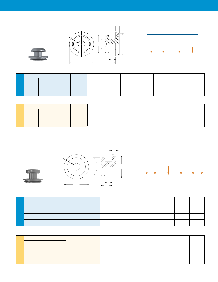
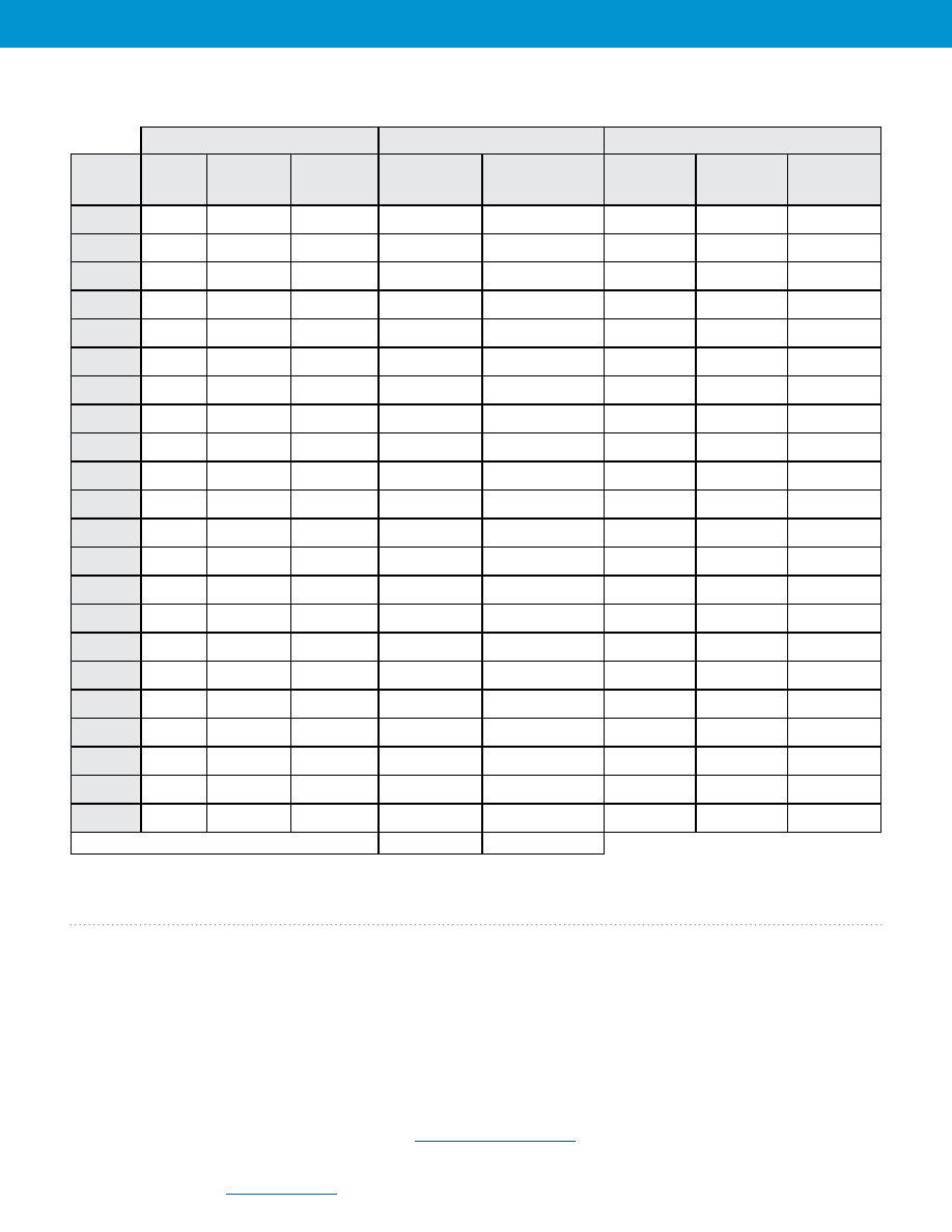
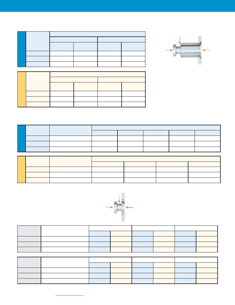
SKC-F™/SK4-F™ Fastener Dimensional Data
SK C – F
1.5
SK 4 – F
1.5
Type
Face
Mounting
Designation
Code
Part Number Designation
Material
Code
Sheet
Thickness
Code
H
N
C
B
A
S
M
PEM “dimple”
registered
trademark.
Clinching profile may vary.
Type
Face
Top Sheet
A
B
C
H
M
N
S
300 Series 400 Series
Mounting
Thickness
Max.
± .003
Max.
Nom.
Max.
± .003
±.003
Stainless Stainless
Hardened
Designation Code
Steel
Steel
Steel
Code
SKCF
SK4F
SKSF
F
1.5
.039
.177
.212
.237
.108
.099
.068
TSKCF
TSK4F
TSKSF
F
1.5
.032
.177
.212
.237
.108
.099
.068
Type
Face
Top Sheet
A
B
C
H
M
N
S
300 Series 400 Series
Mounting
Thickness
Max.
± 0.08
Max.
Nom.
Max.
± 0.08
±0.08
Stainless Stainless Hardened
Designation Code
Steel
Steel
Steel
Code
SKCF
SK4F
SKSF
F
1.5
1
4.5
5.39
6.02
2.75
2.5
1.73
TSKCF TSK4F
TSKSF
F
1.5
0.8
4.5
5.39
6.02
2.75
2.5
1.73
All dimensions are in inches.
All dimensions are in millimeters.
SKCF-F™/SK4F-F™/SKSF-F™/ TSKCF-F™/TSK4-F™/TSKSF-F™
Fastener Dimensional Data
Part Number Designation
SK C
F – F
1.5
SK 4
F – F
1.5
SK S
F – F
1.5 - ZI
TSK C
F – F
1.5
TSK 4
F – F
1.5
TSK S
F – F
1.5 - ZI
Type
Face
Mounting
Designation
Code
Material
Code
Sheet
Thickness
Code
Manufacturing
Code
Finish
TSK for .032” / 0.8mm thick panels
H
N
C
B
A
S
M
PEM “dimple”
registered
trademark.
Clinching profile may vary.
Uni
fie
d
Me
tric
Uni
fie
d
Me
tric
Keyhole® Standoffs And Fasteners
SK-5
Type
Face Mounting
Top Sheet
Neck
A
B C H M N
S
Hardened
Designation
Thickness
Diameter
(Shank)
±.003 Max. Nom. Max. ±.003 +.003
Steel Code Code
Code
Max. -.008
2.5
.177
.212
.236
.099
SKS R
1.5 3.2 .039 .217 .235 .276 .148 .126 .107
4.0
.256 .275
.307
.157
2.5
.177
.212
.236
.099
SKS R
2.0 3.2 .039 .217 .235 .276 .167 .126 .127
4.0
.256 .275
.307
.157
2.5
.177
.212
.236
.099
SKS R
2.5 3.2 .039 .217 .235 .276 .187 .126 .147
4.0
.256 .275
.307
.157
All dimensions are in inches.
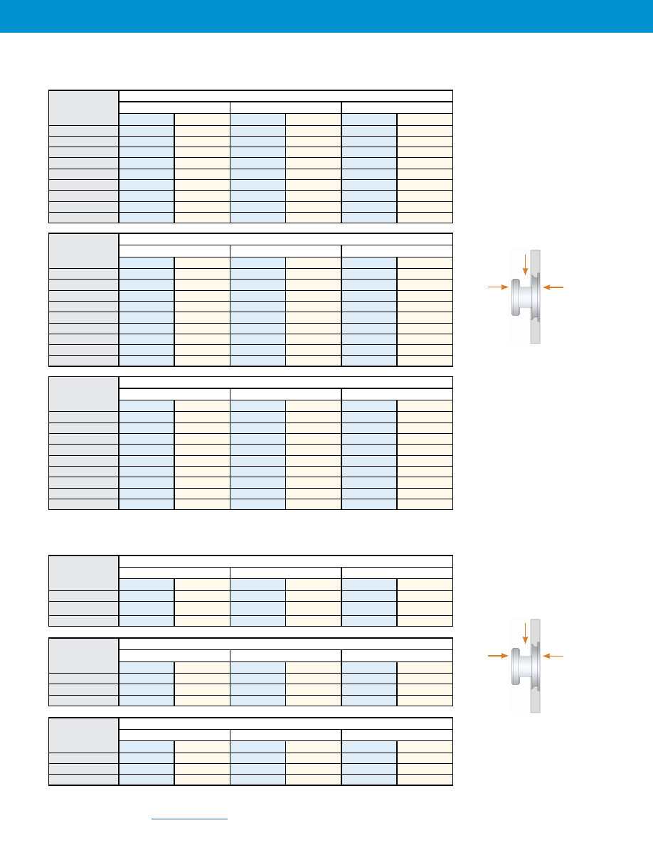
SKS-R™, SKC-R™ AND SK4-R™ Fastener Dimensional Data
All dimensions are in millimeters.
H
N
C
B
A
S
M
PEM “dimple”
registered
trademark.
Clinching profile may vary.
SK S – R
1.5 – 2.5 – ZI
SK C – R
1.5 – 2.5
SK 4 – R
1.5 – 2.5
Type
Face
Mounting
Designation
Code
Part Number Designation
Material
Code
Top Sheet
Thickness
Code
Finish
Neck
Diameter
Code
Type
Face Mounting
Top Sheet
Neck
A
B C H M
N
S
Hardened
Designation
Thickness
Diameter
(Shank)
±0.08 Max. Nom. Max.
±0.08 +0.08
Steel
Code
Code
Code
Max.
-0.21
2.5
4.5
5.39
6
2.5
SKS R
1.5 3.2 1 5.5 5.98 7 3.75 3.2
2.73
4.0
6.5
6.98
7.8
4
2.5
4.5
5.39
6
2.5
SKS R
2.0 3.2 1 5.5 5.98 7 4.25 3.2
3.23
4.0
6.5
6.98
7.8
4
2.5
4.5
5.39
6
2.5
SKS R
2.5 3.2 1 5.5 5.98 7 4.75 3.2
3.73
4.0
6.5
6.98
7.8
4
All dimensions are in millimeters.
Type
Face Mounting
Top Sheet
Neck
A
B C H M N S
300 Series
400 Series
Designation
Thickness
Diameter
(Shank)
±0.08 Max. Nom. Max. ±0.08 ±0.08
Stainless Steel
Stainless Steel
Code
Code
Code
Max.
2.5 4.5 6 7 2.5
SKC SK4 R 1.5 3.2 1 5.5 7 8 3.75 3.2 2.73
4.0 6.5 8 9 4
2.5 4.5 6 7 2.5
SKC SK4 R 2.0 3.2 1 5.5 7 8 4.25 3.2 3.23
4.0 6.5 8 9 4
2.5 4.5 6 7 2.5
SKC SK4 R 2.5 3.2 1 5.5 7 8 4.75 3.2 3.73
4.0 6.5 8 9 4
All dimensions are in inches.
Type
Face Mounting
Top Sheet
Neck
A
B C H M N S
300 Series
400 Series
Designation
Thickness
Diameter
(Shank)
±.003 Max. Nom. Max. ±.003 ±.003
Stainless Steel
Stainless Steel
Code
Code
Code
Max.
2.5 .177 .236 .276 .099
SKC SK4 R
1.5 3.2 .039 .217 .276 .315 .148 .126 .107
4.0 .256 .315 .354 .157
2.5 .177 .236 .276 .099
SKC SK4 R
2.0 3.2 .039 .217 .276 .315 .167 .126 .127
4.0 .256 .315 .354 .157
2.5 .177 .236 .276 .099
SKC SK4 R
2.5 3.2 .039 .217 .276 .315 .187 .126 .147
4.0 .256 .315 .354 .157
Uni
fie
d
Uni
fie
d
Me
tric
Me
tric
Keyhole® Standoffs And Fasteners
SK-6
TSKS-R™, TSKC-R™, TSK4-R™, HSKS-R™, HSKC-R™ AND HSK4-R™
Fastener Dimensional Data
H
N
C
B
A
S
M
PEM “dimple”
registered
trademark.
Clinching profile may vary.
TSK C – R
1.5 – 2.5
TSK 4 – R
1.5 – 2.5
TSK S – R
1.5 – 2.5 – ZI
HSK C – R
1.5 – 2.5
HSK 4 – R
1.5 – 2.5
HSK S – R
1.5 – 2.5 – ZI
Type
Face
Mounting
Designation
Code
Part Number Designation
Material
Code
Top Sheet
Thickness
Code
Finish
Neck
Diameter
Code
All dimensions are in millimeters.
All dimensions are in inches.
TSK for .032” / 0.8mm thick panels
HSK for .047” / 1.2mm thick panels
All dimensions are in millimeters.
All dimensions are in inches.
Type
Face Mounting
Designation
Code
Top Sheet
Thickness
Code
Neck
Diameter
Code
A
(Shank)
Max.
B
±0.08
C
Max.
H
Nom.
M
Max.
N
±0.08
S
±0.08
Hardened
Steel
300 Series
Stainless Steel
400 Series
Stainless Steel
TSKS
TSKC
TSK4
R
1.5
2.5
0.8
4.5
6
7
3.55
2.5
2.53
TSKS
TSKC
TSK4
R
2.0
2.5
0.8
4.5
6
7
4.05
2.5
3.03
TSKS
TSKC
TSK4
R
2.5
2.5
0.8
4.5
6
7
4.55
2.5
3.53
Type
Face Mounting
Designation
Code
Top Sheet
Thickness
Code
Neck
Diameter
Code
A
(Shank)
Max.
B
±.003
C
Max.
H
Nom.
M
Max.
N
±.003
S
±.003
Hardened
Steel
300 Series
Stainless Steel
400 Series
Stainless Steel
TSKS
TSKC
TSK4
R
1.5
2.5
.032
.177
.236
.276
.140
.099
.100
TSKS
TSKC
TSK4
R
2.0
2.5
.032
.177
.236
.276
.159
.099
.119
TSKS
TSKC
TSK4
R
2.5
2.5
.032
.177
.236
.276
.179
.099
.139
Type
Face Mounting
Designation
Code
Top Sheet
Thickness
Code
Neck
Diameter
Code
A
(Shank)
Max.
B
±.003
C
Max.
H
Nom.
M
Max.
N
±.003
S
±.003
Hardened
Steel
300 Series
Stainless Steel
400 Series
Stainless Steel
HSKS
HSKC
HSK4
R
1.5
2.5
.047
.177
.236
.276
.156
.099
.115
3.2
.217
.276
.315
.126
4.0
.256
.315
.354
.157
HSKS
HSKC
HSK4
R
2.0
2.5
.047
.177
.236
.276
.175
.099
.135
3.2
.217
.276
.315
.126
4.0
.256
.315
.354
.157
HSKS
HSKC
HSK4
R
2.5
2.5
.047
.177
.236
.276
.198
.099
.155
3.2
.217
.276
.315
.126
4.0
.256
.315
.354
.157
Type
Face Mounting
Designation
Code
Top Sheet
Thickness
Code
Neck
Diameter
Code
A
(Shank)
Max.
B
±0.08
C
Max.
H
Nom.
M
Max.
N
±0.08
S
±0.08
Hardened
Steel
300 Series
Stainless Steel
400 Series
Stainless Steel
HSKS
HSKC
HSK4
R
1.5
2.5
1.2
4.5
6
7
3.95
2.5
2.93
3.2
5.5
7
8
3.2
4.0
6.5
8
9
4
HSKS
HSKC
HSK4
R
2.0
2.5
1.2
4.5
6
7
4.45
2.5
3.43
3.2
5.5
7
8
3.2
4.0
6.5
8
9
4
HSKS
HSKC
HSK4
R
2.5
2.5
1.2
4.5
6
7
4.95
2.5
3.93
3.2
5.5
7
8
3.2
4.0
6.5
8
9
4
HSKS
—
—
R
1.2
4.0
1.2
7
8
9.5
3.9
4
2.6
Uni
fie
d
Me
tric
Keyhole® Standoffs And Fasteners
SK-7
PennEngineering •
All dimensions are in inches.
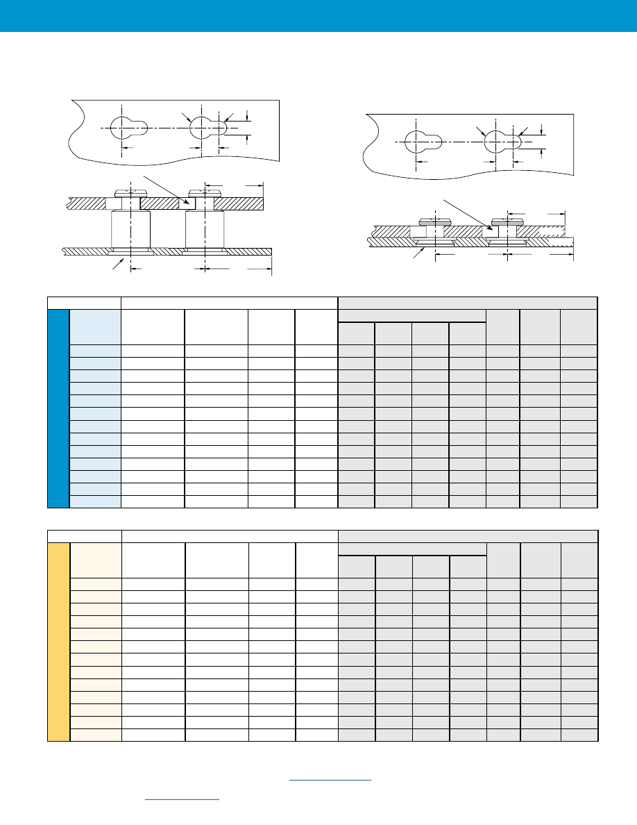
SKC™/SK4™/ SKCF™/SK4F™/SKSF™ Standoffs
A
1
Rad.
A
3
Dia.
Mounting Hole A in Panel 2
Location
Tolerance
±.005” / ±0.13 mm
A
2
A
4
Application Data
Panel 1
Panel 2
Type
Bottom
Mounting Hole B
+.003 –.000
Sheet
Hardness
Max.
(1)
Min. Sheet
Thickness
Edge
Distance
C1 Min.
(4)
Top Mounting Hole A
Material
Thickness
Range
Edge
Distance
C2 Min.
(4)
A1
Nom.
A2
±.003
A3
±.003
A4
Min.
SKC-6060
.213
HRB 70 / HB 125
.040
.260
.059
.118
.197
.148
ANY
.057 - .064
.160
SK4-6060
.213
HRB 88 / HB 183
.040
.260
.059
.118
.197
.148
ANY
.057 - .064
.160
SKCF-6060
.213
HRB 70 / HB 125
.040
.260
.059
.118
.197
.148
ANY
.057 - .064
.160
SK4F-6060
.213
HRB 88 / HB 183
.040
.260
.059
.118
.197
.148
ANY
.057 - .064
.160
SKSF-6060
.213
HRB 80 / HB 150
.040
.260
.059
.118
.197
.148
ANY
.057 - .064
.160
SKC-F1.5
.213
HRB 70 / HB 125
.040
(2)
.150
.059
.118
.197
.148
ANY
.057 - .064
.160
SK4-F1.5
.213
HRB 88 / HB 183
.040
(2)
.150
.059
.118
.197
.148
ANY
.057 - .064
.160
SKCF-F1.5
.213
HRB 70 / HB 125
.040
(2)
.150
.059
.118
.197
.148
ANY
.057 - .064
.160
SK4F-F1.5
.213
HRB 88 / HB 183
.040
(2)
.150
.059
.118
.197
.148
ANY
.057 - .064
.160
SKSF-F1.5
.213
HRB 80 / HB 150
.040
(2)
.150
.059
.118
.197
.148
ANY
.057 - .064
.160
TSKCF-F1.5
.213
HRB 70 / HB 125
.032
(3)
.150
.059
.118
.197
.148
ANY
.057 - .064
.160
TSK4F-F1.5
.213
HRB 88 / HB 183
.032
(3)
.150
.059
.118
.197
.148
ANY
.057 - .064
.160
TSKSF-F1.5
.213
HRB 80 / HB 150
.032
(3)
.150
.059
.118
.197
.148
ANY
.057 - .064
.160
Panel 1
Panel 2
Type
Bottom
Mounting Hole B
+0.08
Sheet
Hardness
Max.
(1)
Min. Sheet
Thickness
Edge
Distance
C1 Min.
(4)
Top Mounting Hole A
Material
Thickness
Range
Edge
Distance
C2 Min.
(4)
A1
Nom.
A2
±0.08
A3
±0.08
A4
Min.
SKC-61.5
5.41
HRB 70 / HB 125
1
6.6
1.5
3
5
3.75
ANY
1.45 - 1.62
4.1
SK4-61.5
5.41
HRB 88 / HB 183
1
6.6
1.5
3
5
3.75
ANY
1.45 - 1.62
4.1
SKCF-61.5
5.41
HRB 70 / HB 125
1
6.6
1.5
3
5
3.75
ANY
1.45 - 1.62
4.1
SK4F-61.5
5.41
HRB 88 / HB 183
1
6.6
1.5
3
5
3.75
ANY
1.45 - 1.62
4.1
SKSF-61.5
5.41
HRB 80 / HB 150
1
6.6
1.5
3
5
3.75
ANY
1.45 - 1.62
4.1
SKC-F1.5
5.41
HRB 70 / HB 125
1
(2)
3.8
1.5
3
5
3.75
ANY
1.45 - 1.62
4.1
SK4-F1.5
5.41
HRB 88 / HB 183
1
(2)
3.8
1.5
3
5
3.75
ANY
1.45 - 1.62
4.1
SKCF-F1.5
5.41
HRB 70 / HB 125
1
(2)
3.8
1.5
3
5
3.75
ANY
1.45 - 1.62
4.1
SK4F-F1.5
5.41
HRB 88 / HB 183
1
(2)
3.8
1.5
3
5
3.75
ANY
1.45 - 1.62
4.1
SKSF-F1.5
5.41
HRB 80 / HB 150
1
(2)
3.8
1.5
3
5
3.75
ANY
1.45 - 1.62
4.1
TSKCF-F1.5
5.41
HRB 70 / HB 125
0.8
(3)
3.8
1.5
3
5
3.75
ANY
1.45 - 1.62
4.1
TSK4F-F1.5
5.41
HRB 88 / HB 183
0.8
(3)
3.8
1.5
3
5
3.75
ANY
1.45 - 1.62
4.1
TSKSF-F1.5
5.41
HRB 80 / HB 150
0.8
(3)
3.8
1.5
3
5
3.75
ANY
1.45 - 1.62
4.1
All dimensions are in millimeters.
(1) HRB - Hardness Rockwell “B” Scale. HB - Hardness Brinell.
(2) SKC-F™/SK4-F™/ SKCF-F™/SK4F-F™/SKSF-F™ fasteners may also be installed into a .043”/1.1mm minimum depth blind milled hole in a .062”/1.6mm minimum sheet thickness.
(3) TSKCF-F™/TSK4F-F™/TSKSF-F™ fasteners may also be installed into a .035”/0.9mm minimum depth blind milled hole in a .055”/1.4mm minimum sheet thickness.
(4) For more information on proximity to bends and distance to other clinch hardware, see
.
SKC-F™/SK4-F™/ SKCF-F™/SK4-F™/SKSF-F™/
TSKCF-F™/TSK4-F™/TSKSF-F™ Fasteners
Edge
C
2
Edge
C
1
PANEL 2
PANEL 1
Mounting Hole B
Mounting Hole A
Mounting
Hole Location
Tolerance
±.005” / ±0.13 mm
A
1
Rad.
A
3
Dia.
Mounting Hole A in Panel 2
Location
Tolerance
±.005” / ±0.13 mm
A
2
A
4
Edge
C
2
Edge
C
1
Mounting Hole B
Mounting Hole A
PANEL 2
PANEL 1
Mounting Hole
Location Tolerance
±.005” / ±0.13 mm
Uni
fie
d
Keyhole® Standoffs And Fasteners
SK-8
All dimensions are in inches.
Bottom Mounting
Edge
Top Mounting Hole A
Edge
Type
Hole B
Sheet Hardness Thickness Distance A
1
A
2
A
3
A
4
Thickness Distance
+ .003 –.000
Max. (1)
Range
C
1
Min. (2)
Nom.
± .003
± .003
Min.
Material
Max.
C
2
Min. (2)
SKS-R1.5-2.5-ZI
.213
HRB 80 / HB 150
.040 - .047
.236
.059
.118
.197
.148
ANY
.060
.160
SKS-R1.5-3.2-ZI
.236
HRB 80 / HB 150
.040 - .047
.236
.073
.146
.236
.181
ANY
.060
.201
SKS-R1.5-4.0-ZI
.276
HRB 80 / HB 150
.040 - .047
.236
.089
.177
.276
.217
ANY
.060
.240
SKS-R2.0-2.5-ZI
.213
HRB 80 / HB 150
.040 - .047
.236
.059
.118
.197
.148
ANY
.080
.160
SKS-R2.0-3.2-ZI
.236
HRB 80 / HB 150
.040 - .047
.236
.073
.146
.236
.181
ANY
.080
.201
SKS-R2.0-4.0-ZI
.276
HRB 80 / HB 150
.040 - .047
.236
.089
.177
.276
.217
ANY
.080
.240
SKS-R2.5-2.5-ZI
.213
HRB 80 / HB 150
.040 - .047
.236
.059
.118
.197
.148
ANY
.100
.160
SKS-R2.5-3.2-ZI
.236
HRB 80 / HB 150
.040 - .047
.236
.073
.146
.236
.181
ANY
.100
.201
SKS-R2.5-4.0-ZI
.276
HRB 80 / HB 150
.040 - .047
.236
.089
.177
.276
.217
ANY
.100
.240
SKC-R1.5-2.5
.237
HRB 70 / HB 125
.040 - .047
.276
.059
.118
.197
.148
ANY
.060
.160
SKC-R1.5-3.2
.277
HRB 70 / HB 125
.040 - .047
.295
.073
.146
.236
.181
ANY
.060
.201
SKC-R1.5-4.0
.316
HRB 70 / HB 125
.040 - .047
.315
.089
.177
.276
.217
ANY
.060
.240
SKC-R2.0-2.5
.237
HRB 70 / HB 125
.040 - .047
.276
.059
.118
.197
.148
ANY
.080
.160
SKC-R2.0-3.2
.277
HRB 70 / HB 125
.040 - .047
.295
.073
.146
.236
.181
ANY
.080
.201
SKC-R2.0-4.0
.316
HRB 70 / HB 125
.040 - .047
.315
.089
.177
.276
.217
ANY
.080
.240
SKC-R2.5-2.5
.237
HRB 70 / HB 125
.040 - .047
.276
.059
.118
.197
.148
ANY
.100
.160
SKC-R2.5-3.2
.277
HRB 70 / HB 125
.040 - .047
.295
.073
.146
.236
.181
ANY
.100
.201
SKC-R2.5-4.0
.316
HRB 70 / HB 125
.040 - .047
.315
.089
.177
.276
.217
ANY
.100
.240
SK4-R1.5-2.5
.237
HRB 88 / HB 183
.040 - .047
.276
.059
.118
.197
.148
ANY
.060
.160
SK4-R1.5-3.2
.277
HRB 88 / HB 183
.040 - .047
.295
.073
.146
.236
.181
ANY
.060
.201
SK4-R1.5-4.0
.316
HRB 88 / HB 183
.040 - .047
.315
.089
.177
.276
.217
ANY
.060
.240
SK4-R2.0-2.5
.237
HRB 88 / HB 183
.040 - .047
.276
.059
.118
.197
.148
ANY
.080
.160
SK4-R2.0-3.2
.277
HRB 88 / HB 183
.040 - .047
.295
.073
.146
.236
.181
ANY
.080
.201
SK4-R2.0-4.0
.316
HRB 88 / HB 183
.040 - .047
.315
.089
.177
.276
.217
ANY
.080
.240
SK4-R2.5-2.5
.237
HRB 88 / HB 183
.040 - .047
.276
.059
.118
.197
.148
ANY
.100
.160
SK4-R2.5-3.2
.277
HRB 88 / HB 183
.040 - .047
.295
.073
.146
.236
.181
ANY
.100
.201
SK4-R2.5-4.0
.316
HRB 88 / HB 183
.040 - .047
.315
.089
.177
.276
.217
ANY
.100
.240
TSKS-R1.5-2.5-ZI
.237
HRB 80 / HB 150
.032 - .038
.276
.059
.118
.197
.148
ANY
.060
.160
TSKS-R2.0-2.5-ZI
.237
HRB 80 / HB 150
.032 - .038
.276
.059
.118
.197
.148
ANY
.080
.160
TSKS-R2.5-2.5-ZI
.237
HRB 80 / HB 150
.032 - .038
.276
.059
.118
.197
.148
ANY
.100
.160
HSKS-R1.5-2.5-ZI
.237
HRB 80 / HB 150
.047 - .055
.276
.059
.118
.197
.148
ANY
.060
.160
HSKS-R1.5-3.2-ZI
.277
HRB 80 / HB 150
.047 - .055
.295
.073
.146
.236
.181
ANY
.060
.201
HSKS-R1.5-4.0-ZI
.316
HRB 80 / HB 150
.047 - .055
.315
.089
.177
.276
.217
ANY
.060
.240
HSKS-R2.0-2.5-ZI
.237
HRB 80 / HB 150
.047 - .055
.276
.059
.118
.197
.148
ANY
.080
.160
HSKS-R2.0-3.2-ZI
.277
HRB 80 / HB 150
.047 - .055
.295
.073
.146
.236
.181
ANY
.080
.201
HSKS-R2.0-4.0-ZI
.316
HRB 80 / HB 150
.047 - .055
.315
.089
.177
.276
.217
ANY
.080
.240
HSKS-R2.5-2.5-ZI
.237
HRB 80 / HB 150
.047 - .055
.276
.059
.118
.197
.148
ANY
.100
.160
HSKS-R2.5-3.2-ZI
.277
HRB 80 / HB 150
.047 - .055
.295
.073
.146
.236
.181
ANY
.100
.201
HSKS-R2.5-4.0-ZI
.316
HRB 80 / HB 150
.047 - .055
.315
.089
.177
.276
.217
ANY
.100
.240
TSKC-R1.5-2.5
.237
HRB 70 / HB 125
.032 - .038
.276
.059
.118
.197
.148
ANY
.060
.160
TSKC-R2.0-2.5
.237
HRB 70 / HB 125
.032 - .038
.276
.059
.118
.197
.148
ANY
.080
.160
TSKC-R2.5-2.5
.237
HRB 70 / HB 125
.032 - .038
.276
.059
.118
.197
.148
ANY
.100
.160
HSKC-R1.5-2.5
.237
HRB 70 / HB 125
.047 - .055
.276
.059
.118
.197
.148
ANY
.060
.160
HSKC-R1.5-3.2
.277
HRB 70 / HB 125
.047 - .055
.295
.073
.146
.236
.181
ANY
.060
.201
HSKC-R1.5-4.0
.316
HRB 70 / HB 125
.047 - .055
.315
.089
.177
.276
.217
ANY
.060
.240
HSKC-R2.0-2.5
.237
HRB 70 / HB 125
.047 - .055
.276
.059
.118
.197
.148
ANY
.080
.160
HSKC-R2.0-3.2
.277
HRB 70 / HB 125
.047 - .055
.295
.073
.146
.236
.181
ANY
.080
.201
HSKC-R2.0-4.0
.316
HRB 70 / HB 125
.047 - .055
.315
.089
.177
.276
.217
ANY
.080
.240
HSKC-R2.5-2.5
.237
HRB 70 / HB 125
.047 - .055
.276
.059
.118
.197
.148
ANY
.100
.160
HSKC-R2.5-3.2
.277
HRB 70 / HB 125
.047 - .055
.295
.073
.146
.236
.181
ANY
.100
.201
HSKC-R2.5-4.0
.316
HRB 70 / HB 125
.047 - .055
.315
.089
.177
.276
.217
ANY
.100
.240
TSK4-R1.5-2.5
.237
HRB 88 / HB 183
.032 - .038
.276
.059
.118
.197
.148
ANY
.060
.160
TSK4-R2.0-2.5
.237
HRB 88 / HB 183
.032 - .038
.276
.059
.118
.197
.148
ANY
.080
.160
TSK4-R2.5-2.5
.237
HRB 88 / HB 183
.032 - .038
.276
.059
.118
.197
.148
ANY
.100
.160
HSK4-R1.5-2.5
.237
HRB 88 / HB 183
.047 - .055
.276
.059
.118
.197
.148
ANY
.060
.160
HSK4-R1.5-3.2
.277
HRB 88 / HB 183
.047 - .055
.295
.073
.146
.236
.181
ANY
.060
.201
HSK4-R1.5-4.0
.316
HRB 88 / HB 183
.047 - .055
.315
.089
.177
.276
.217
ANY
.060
.240
HSK4-R2.0-2.5
.237
HRB 88 / HB 183
.047 - .055
.276
.059
.118
.197
.148
ANY
.080
.160
HSK4-R2.0-3.2
.277
HRB 88 / HB 183
.047 - .055
.295
.073
.146
.236
.181
ANY
.080
.201
HSK4-R2.0-4.0
.316
HRB 88 / HB 183
.047 - .055
.315
.089
.177
.276
.217
ANY
.080
.240
HSK4-R2.5-2.5
.237
HRB 88 / HB 183
.047 - .055
.276
.059
.118
.197
.148
ANY
.100
.160
HSK4-R2.5-3.2
.277
HRB 88 / HB 183
.047 - .055
.295
.073
.146
.236
.181
ANY
.100
.201
HSK4-R2.5-4.0
.316
HRB 88 / HB 183
.047 - .055
.315
.089
.177
.276
.217
ANY
.100
.240
PANEL 1
PANEL 2
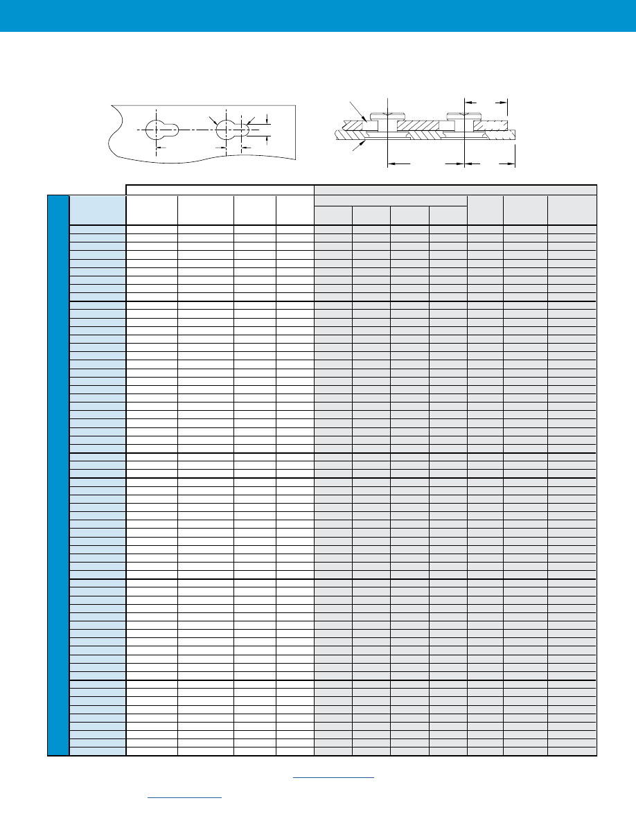
Application Data — SKS-R™/SKC-R™/SK4-R™/ TSKS-R™/HSKS-R™/
TSKC-R™/TSK4-R™/HSKC-R™/HSK4-R™ Fasteners
Mounting Hole A in Panel 2
A
1
Rad.
A
3
Dia.
Location
Tolerance
±.005” / ±0.13 mm
A
2
A
4
Edge
C
2
Edge
C
1
PANEL 2
PANEL 1
Mounting
Hole B
Mounting
Hole A
Mounting
Hole Location
Tolerance
±.005” / ±0.13 mm
(1) HRB - Hardness Rockwell “B” Scale. HB - Hardness Brinell.
(2) For more information on proximity to bends and distance to other clinch hardware, see
.
Me
tric
Keyhole® Standoffs And Fasteners
SK-9
PennEngineering •
All dimensions are in millimeterrs.
Bottom Mounting
Edge
Top Mounting Hole A
Edge
Type
Hole B
Sheet Hardness Thickness Distance A
1
A
2
A
3
A
4
Thickness Distance
+ 0.08
Max. (1)
Range
C
1
Min. (2)
Nom.
±0.08
± 0.08
Min.
Material
Max.
C
2
Min. (2)
SKS-R1.5-2.5-ZI
5.41
HRB 80 / HB 150
1-1.19
6
1.5
3
5
3.75
ANY
1.54
4.1
SKS-R1.5-3.2-ZI
6
HRB 80 / HB 150
1-1.19
6
1.85
3.7
6
4.6
ANY
1.54
5.1
SKS-R1.5-4.0-ZI
7
HRB 80 / HB 150
1-1.19
6
2.25
4.5
7
5.5
ANY
1.54
6.1
SKS-R2.0-2.5-ZI
5.41
HRB 80 / HB 150
1-1.19
6
1.5
3
5
3.75
ANY
2.04
4.1
SKS-R2.0-3.2-ZI
6
HRB 80 / HB 150
1-1.19
6
1.85
3.7
6
4.6
ANY
2.04
5.1
SKS-R2.0-4.0-ZI
7
HRB 80 / HB 150
1-1.19
6
2.25
4.5
7
5.5
ANY
2.04
6.1
SKS-R2.5-2.5-ZI
5.41
HRB 80 / HB 150
1-1.19
6
1.5
3
5
3.75
ANY
2.54
4.1
SKS-R2.5-3.2-ZI
6
HRB 80 / HB 150
1-1.19
6
1.85
3.7
6
4.6
ANY
2.54
5.1
SKS-R2.5-4.0-ZI
7
HRB 80 / HB 150
1-1.19
6
2.25
4.5
7
5.5
ANY
2.54
6.1
SKC-R1.5-2.5
6.02
HRB 70 / HB 125
1-1.19
7
1.5
3
5
3.75
ANY
1.54
4.1
SKC-R1.5-3.2
7.02
HRB 70 / HB 125
1-1.19
7.5
1.85
3.7
6
4.6
ANY
1.54
5.1
SKC-R1.5-4.0
8.02
HRB 70 / HB 125
1-1.19
8
2.25
4.5
7
5.5
ANY
1.54
6.1
SKC-R2.0-2.5
6.02
HRB 70 / HB 125
1-1.19
7
1.5
3
5
3.75
ANY
2.04
4.1
SKC-R2.0-3.2
7.02
HRB 70 / HB 125
1-1.19
7.5
1.85
3.7
6
4.6
ANY
2.04
5.1
SKC-R2.0-4.0
8.02
HRB 70 / HB 125
1-1.19
8
2.25
4.5
7
5.5
ANY
2.04
6.1
SKC-R2.5-2.5
6.02
HRB 70 / HB 125
1-1.19
7
1.5
3
5
3.75
ANY
2.54
4.1
SKC-R2.5-3.2
7.02
HRB 70 / HB 125
1-1.19
7.5
1.85
3.7
6
4.6
ANY
2.54
5.1
SKC-R2.5-4.0
8.02
HRB 70 / HB 125
1-1.19
8
2.25
4.5
7
5.5
ANY
2.54
6.1
SK4-R1.5-2.5
6.02
HRB 88 / HB 183
1-1.19
7
1.5
3
5
3.75
ANY
1.54
4.1
SK4-R1.5-3.2
7.02
HRB 88 / HB 183
1-1.19
7.5
1.85
3.7
6
4.6
ANY
1.54
5.1
SK4-R1.5-4.0
8.02
HRB 88 / HB 183
1-1.19
8
2.25
4.5
7
5.5
ANY
1.54
6.1
SK4-R2.0-2.5
6.02
HRB 88 / HB 183
1-1.19
7
1.5
3
5
3.75
ANY
2.04
4.1
SK4-R2.0-3.2
7.02
HRB 88 / HB 183
1-1.19
7.5
1.85
3.7
6
4.6
ANY
2.04
5.1
SK4-R2.0-4.0
8.02
HRB 88 / HB 183
1-1.19
8
2.25
4.5
7
5.5
ANY
2.04
6.1
SK4-R2.5-2.5
6.02
HRB 88 / HB 183
1-1.19
7
1.5
3
5
3.75
ANY
2.54
4.1
SK4-R2.5-3.2
7.02
HRB 88 / HB 183
1-1.19
7.5
1.85
3.7
6
4.6
ANY
2.54
5.1
SK4-R2.5-4.0
8.02
HRB 88 / HB 183
1-1.19
8
2.25
4.5
7
5.5
ANY
2.54
6.1
TSKS-R1.5-2.5-ZI
6.02
HRB 80 / HB 150
0.8-0.95
7
1.5
3
5
3.75
ANY
1.54
4.1
TSKS-R2.0-2.5-ZI
6.02
HRB 80 / HB 150
0.8-0.95
7
1.5
3
5
3.75
ANY
2.04
4.1
TSKS-R2.5-2.5-ZI
6.02
HRB 80 / HB 150
0.8-0.95
7
1.5
3
5
3.75
ANY
2.54
4.1
HSKS-R1.5-2.5-ZI
6.02
HRB 80 / HB 150
1.2-1.39
7
1.5
3
5
3.75
ANY
1.54
4.1
HSKS-R1.5-3.2-ZI
7.02
HRB 80 / HB 150
1.2-1.39
7.5
1.85
3.7
6
4.6
ANY
1.54
5.1
HSKS-R1.5-4.0-ZI
8.02
HRB 80 / HB 150
1.2-1.39
8
2.25
4.5
7
5.5
ANY
1.54
6.1
HSKS-R2.0-2.5-ZI
6.02
HRB 80 / HB 150
1.2-1.39
7
1.5
3
5
3.75
ANY
2.04
4.1
HSKS-R2.0-3.2-ZI
7.02
HRB 80 / HB 150
1.2-1.39
7.5
1.85
3.7
6
4.6
ANY
2.04
5.1
HSKS-R2.0-4.0-ZI
8.02
HRB 80 / HB 150
1.2-1.39
8
2.25
4.5
7
5.5
ANY
2.04
6.1
HSKS-R2.5-2.5-ZI
6.02
HRB 80 / HB 150
1.2-1.39
7
1.5
3
5
3.75
ANY
2.54
4.1
HSKS-R2.5-3.2-ZI
7.02
HRB 80 / HB 150
1.2-1.39
7.5
1.85
3.7
6
4.6
ANY
2.54
5.1
HSKS-R2.5-4.0-ZI
8.02
HRB 80 / HB 150
1.2-1.39
8
2.25
4.5
7
5.5
ANY
2.54
6.1
HSKS-R1.2-4.0-ZI
8.02
HRB 80 / HB 150
1.2-1.39
8
2.25
4.5
7.5
5.75
ANY
1.21
6.6
TSKC-R1.5-2.5
6.02
HRB 70 / HB 125
0.8-0.95
7
1.5
3
5
3.75
ANY
1.54
4.1
TSKC-R2.0-2.5
6.02
HRB 70 / HB 125
0.8-0.95
7
1.5
3
5
3.75
ANY
2.04
4.1
TSKC-R2.5-2.5
6.02
HRB 70 / HB 125
0.8-0.95
7
1.5
3
5
3.75
ANY
2.54
4.1
HSKC-R1.5-2.5
6.02
HRB 70 / HB 125
1.2-1.39
7
1.5
3
5
3.75
ANY
1.54
4.1
HSKC-R1.5-3.2
7.02
HRB 70 / HB 125
1.2-1.39
7.5
1.85
3.7
6
4.6
ANY
1.54
5.1
HSKC-R1.5-4.0
8.02
HRB 70 / HB 125
1.2-1.39
8
2.25
4.5
7
5.5
ANY
1.54
6.1
HSKC-R2.0-2.5
6.02
HRB 70 / HB 125
1.2-1.39
7
1.5
3
5
3.75
ANY
2.04
4.1
HSKC-R2.0-3.2
7.02
HRB 70 / HB 125
1.2-1.39
7.5
1.85
3.7
6
4.6
ANY
2.04
5.1
HSKC-R2.0-4.0
8.02
HRB 70 / HB 125
1.2-1.39
8
2.25
4.5
7
5.5
ANY
2.04
6.1
HSKC-R2.5-2.5
6.02
HRB 70 / HB 125
1.2-1.39
7
1.5
3
5
3.75
ANY
2.54
4.1
HSKC-R2.5-3.2
7.02
HRB 70 / HB 125
1.2-1.39
7.5
1.85
3.7
6
4.6
ANY
2.54
5.1
HSKC-R2.5-4.0
8.02
HRB 70 / HB 125
1.2-1.39
8
2.25
4.5
7
5.5
ANY
2.54
6.1
TSK4-R1.5-2.5
6.02
HRB 88 / HB 183
0.8-0.95
7
1.5
3
5
3.75
ANY
1.54
4.1
TSK4-R2.0-2.5
6.02
HRB 88 / HB 183
0.8-0.95
7
1.5
3
5
3.75
ANY
2.04
4.1
TSK4-R2.5-2.5
6.02
HRB 88 / HB 183
0.8-0.95
7
1.5
3
5
3.75
ANY
2.54
4.1
HSK4-R1.5-2.5
6.02
HRB 88 / HB 183
1.2-1.39
7
1.5
3
5
3.75
ANY
1.54
4.1
HSK4-R1.5-3.2
7.02
HRB 88 / HB 183
1.2-1.39
7.5
1.85
3.7
6
4.6
ANY
1.54
5.1
HSK4-R1.5-4.0
8.02
HRB 88 / HB 183
1.2-1.39
8
2.25
4.5
7
5.5
ANY
1.54
6.1
HSK4-R2.0-2.5
6.02
HRB 88 / HB 183
1.2-1.39
7
1.5
3
5
3.75
ANY
2.04
4.1
HSK4-R2.0-3.2
7.02
HRB 88 / HB 183
1.2-1.39
7.5
1.85
3.7
6
4.6
ANY
2.04
5.1
HSK4-R2.0-4.0
8.02
HRB 88 / HB 183
1.2-1.39
8
2.25
4.5
7
5.5
ANY
2.04
6.1
HSK4-R2.5-2.5
6.02
HRB 88 / HB 183
1.2-1.39
7
1.5
3
5
3.75
ANY
2.54
4.1
HSK4-R2.5-3.2
7.02
HRB 88 / HB 183
1.2-1.39
7.5
1.85
3.7
6
4.6
ANY
2.54
5.1
HSK4-R2.5-4.0
8.02
HRB 88 / HB 183
1.2-1.39
8
2.25
4.5
7
5.5
ANY
2.54
6.1
PANEL 1
PANEL 2
Application Data — SKS-R™/SKC-R™/SK4-R™/ TSKS-R™/HSKS-R™/
TSKC-R™/TSK4-R™/HSKC-R™/HSK4-R™ Fasteners
Mounting Hole A in Panel 2
A
1
Rad.
A
3
Dia.
Location
Tolerance
±.005” / ±0.13 mm
A
2
A
4
Edge
C
2
Edge
C
1
PANEL 2
PANEL 1
Mounting
Hole B
Mounting
Hole A
Mounting
Hole Location
Tolerance
±.005” / ±0.13 mm
(1) HRB - Hardness Rockwell “B” Scale. HB - Hardness Brinell.
(2) For more information on proximity to bends and distance to other clinch hardware, see
.
Keyhole® Standoffs And Fasteners
SK-10
PennEngineering •
A Note About 400 Series Fasteners For Stainless Steel Panels
In order for self-clinching fasteners to work properly, the fastener must be harder than the sheet into which
it is being installed. In the case of stainless steel panels, fasteners made from 300 Series Stainless Steel do
not meet this hardness criteria. It is for this reason that 400 series fasteners (SK4 and SK4-F) are offered.
However, while these 400 Series fasteners install and perform well in 300 Series stainless sheets they should
not be used if the end product:
• Will be exposed to any appreciable corrosive presence.
• Requires non-magnetic fasteners.
• Will be exposed to any temperatures above 300˚F (149˚C)
If any of the these are issues, please contact
for other options.
(1) HRB - Hardness Rockwell “B” Scale. HB - Hardness Brinell.
(2) See PEM Technical Support section of our web site for related plating standards and specifications.
Material And Finish Specifications
Fastener Materials
Standard Finishes
For Use in Sheet Hardness
(1)
Type
Hardened
Steel
300 Series
Stainless Steel
Hardened 400
Series Stainless
Steel
Passivated and/or
tested per ASTM A380
Zinc Plated per ASTM
B633, SC1 (5µm) Type III,
Colorless
(2)
HRB 88 / HB 183
or less
HRB 80 / HB150
or less
HRB 70 / HB 125
or less
SKC
•
•
•
SK4
•
•
•
SKC-F
•
•
•
SK4-F
•
•
•
SKC-R
•
•
•
SK4-R
•
•
•
SKS-R
•
•
•
TSKC-R
•
•
•
TSK4-R
•
•
•
TSKS-R
•
•
•
HSKS-R
•
•
•
HSKC-R
•
•
•
HSK4-R
•
•
•
SKCF-F
•
•
•
SK4F-F
•
•
•
SKSF-F
•
•
•
TSKCF-F
•
•
•
TSK4F-F
•
•
•
TSKSF-F
•
•
•
SKCF
•
•
•
SK4F
•
•
•
SKSF
•
•
•
Part Number Code for Finishes
None
ZI
Uni
fie
d
Uni
fie
d
Me
tric
Me
tric
Keyhole® Standoffs And Fasteners
SK-11
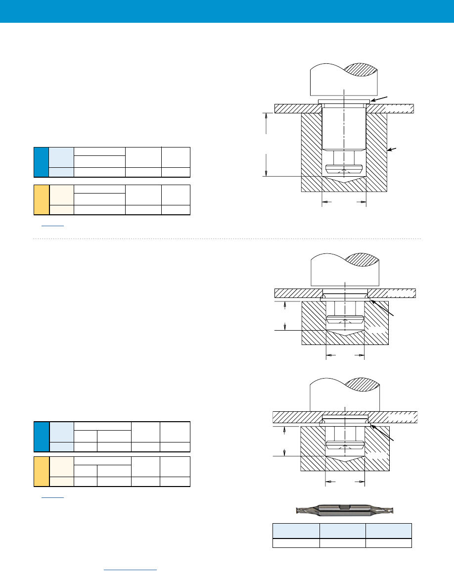
SKC™/SK4™/ SKCF™/SK4F™/SKSF™ Standoffs
1. Prepare properly sized mounting hole in Panel 1.
2. Place the fastener through (punched side of) the mounting hole
and into anvil as shown in figure 1.
3. With installation punch and anvil surfaces parallel, apply only
enough squeezing force to embed the head flush with the panel.
Through Hole Installation Procedure
1. Prepare properly sized mounting hole in Panel 1.
2. Place the fastener into anvil hole as shown in Figure 2.
3. Place the (punch side of) mounting hole over the shank of the fastener.
4. With installation punch and anvil surfaces parallel, apply only enough
squeezing force until flange is flush with panel.
Blind Hole Installation Procedure
1. Mill a properly sized blind hole into Panel 1.
2. Place the fastener into anvil hole as shown in Figure 3.
3. Place the panel mounting hole over the shank of the fastener.
4. With installation punch and anvil surfaces parallel, apply only enough
squeezing force to embed the flange flush with the panel.
SKC-F™/SK4-F™/ SKCF-F™/SK4-F™/SKSF-F™/
TSKCF-F™/TSK4-F™/TSKSF-F™ Fasteners
Installation
Body Size
Anvil Dimension (in.)
Sheet
D
Anvil Part
Punch Part
Code
+.003 -.000 Number Number
6060
.216
970200012300 975200048
Body Size Anvil Dimension (mm)
Sheet
D
Anvil Part
Punch Part
Code
+0.08
Number Number
61.5
5.49
970200012300 975200048
Sheet Anvil Dimensions (in.)
Thickness
L D
Anvil Part
Punch Part
Code
Min.
+.003 -.000 Number Number
1.5 .233
.184
8012608 975200048
Sheet Anvil Dimensions (mm)
Thickness
L D
Anvil Part
Punch Part
Code
Min.
+0.08 Number Number
1.5 5.95
4.67
8012608 975200048
PEMSERTER® Installation Tooling
(1)
PEMSERTER® Installation Tooling
(1)
PUNCH
PANEL 1
L
Min.
Figure 2
FLANGE
D
ANVIL
Figure 3
PUNCH
PANEL 1
L
Min.
FLANGE
D
ANVIL
PUNCH
D
(L+M) +.125” /
(L+M) +3.2 mm
Min.
PANEL 1
Figure 1
HEAD
ANVIL
For “L” and “M”
see page 3.
(1)
for a quote on Haeger® custom installation tooling.
(1)
for a quote on Haeger® custom installation tooling.
Fastener
Required Size
PEM
Type
End Mill
Part No.
SKC-F/SK4-F
.213”
CHM-213
End Mill Information
Double-ended, two-flute H.S.S. center-cutting end mills are available
from stock. PennEngineering does not manufacture center-cutting
end mills, but we do keep a supply in stock for your convenience.
Uni
fie
d
Me
tric
Keyhole® Standoffs And Fasteners
SK-12
PennEngineering •
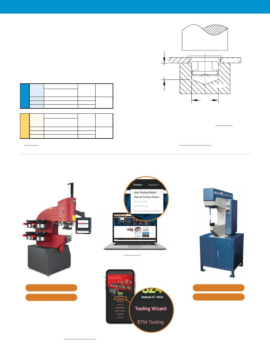
SKS-R™/SKC-R™/SK4-R™/ TSKS-R™/HSKS-R™/ TSKC-R™/
TSK4-R™/HSKC-R™/HSK4-R™ Fasteners
1. Prepare properly sized mounting hole in Panel 1.
2. Place the fastener through (punch side of) the mounting hole
and into anvil as shown.
3. With installation punch and anvil surfaces parallel, apply only
enough squeezing force to embed the head flush with the panel.
Neck Anvil Dimensions (mm)
Diameter
D
Anvil Part
Punch Part
Code
+0.08
Number Number
2.5 4.65 8026244
3.2
5.65
8026245 975200048
4.0
6.65
8026246
PEMSERTER® Installation Tooling
(1)
PUNCH
PANEL 1
M
+.126”/3.2mm
Min.
D
ANVIL
Neck
Anvil Dimensions (in.)
Diameter
D
Anvil Part
Punch Part
Code
+.003 -.000
Number Number
2.5 .183 8026244
3.2
.222
8026245 975200048
4.0
.262
8026246
Installation Notes
• For best results we recommend using a
PEMSERTER® machine for installation of PEM® self-clinching
fasteners. Please check our website for more information.
• Visit the Animation Library on our website to view the
installation process
.
(1)
for a quote on Haeger® custom installation tooling.
For Additional HAEGER® and PEMSERTER® Tooling Information / Part Numbers
Or download the
HAEGER WIZZARD
Phone App
Go to
to access
the Auto and Manual Tooling Wizards
} }
HAEGER® MANUAL TOOLING CATALOG
Uni
fie
d
Uni
fie
d
Uni
fie
d
Me
tric
Me
tric
Me
tric
Keyhole® Standoffs And Fasteners
SK-13
(1) Published installation forces are for general reference. Actual set-up and confirmation of complete installation should be made by observing proper seating of fastener
as described in the installation steps. Other performance values reported are averages when all proper installation parameters and procedures are followed. Variations
in mounting hole size, sheet material, and installation procedure may affect performance. Performance testing this product in your application is recommended. We will
be happy to provide technical assistance and/or samples for this purpose.
(2) .040” / 1 mm test sheet material thickness was used for the -2 and -4 SKC/SK4 standoffs due to the short length of the parts.
Body Size -
Installation
Pushout
Installation
Pushout
Installation
Pushout
Sheet
Code
(lbs.) (lbs.) (lbs.) (lbs.) (lbs.) (lbs.)
SKC-6060
1600
250
3200
600
—
—
SK4-6060
— — — — 9015
720
.060” 5052-H34 Aluminum
.060” Cold-Rolled Steel
Body Size -
Installation
Pushout
Installation
Pushout
Installation
Pushout
Sheet
Code
(kN) (N) (kN) (N) (kN) (N)
SKC-61.5
7.1
1100
14.2
2600
—
—
SK4-61.5
— — — — 40.1
3200
1.52 mm 5052-H34 Aluminum
1.52 mm Cold-Rolled Steel
Length Codes
Body Size -
-2 -4 -6 -8 -10 -12 -14 -16 -18 -20 -24 -28 -32
Sheet Code
Test Sheet Material
Side-Load Force Max. (lbs.)
SKC-6060
5052-H34
Aluminum
130 95 82 63 52 44 38 34 30 27 22 19 17
SKC-6060
Cold-Rolled Steel
185
120
197
153
126
106
92
81
71
66
55
47
42
SK4-6060
300 Series Stainless Steel
400
300
220
180
160
140
120
110
100
100
80
70
50
Type
Installation Pushout Side-Load Force Max. Installation Pushout Side-Load Force Max. Installation Pushout Side-Load Force Max.
(lbs.) (lbs.)
(lbs.)
(lbs.) (lbs.)
(lbs.)
(lbs.) (lbs.)
(lbs.)
SKC-F
1100 120
120
2100 160
185
—
—
—
SK4-F
—
—
—
—
—
—
10210 292
202
.060” 5052-H34 Aluminum
.060” Cold-Rolled Steel
Type
Installation Pushout Side-Load Force Max. Installation Pushout Side-Load Force Max. Installation Pushout Side-Load Force Max.
(kN)
(N) (N) (kN)
(N) (N) (kN)
(N) (N)
SKC-F
4.9 533
533
9.3 711
822
— —
—
SK4-F
—
—
—
—
—
—
45.4 1300
900
1.52 mm 5052-H34 Aluminum
1.52 mm Cold-Rolled Steel
SKC™/SK4™ Standoffs
Installation and pushout
SKC-F™/SK4-F™ Fasteners
Installation, Pushout and Side-load
Test Sheet Material
Test Sheet Material
Test Sheet Material
Side-Load
Installation
Force
Pushout
Side-Load
Installation
Force
Pushout
Performance Data
(1)
SKC™/SK4™ Standoffs
Side-load
.060” 300 Series Stainless Steel
1.52 mm 300 Series Stainless Steel
.060” 300 Series Stainless Steel
1.52 mm 300 Series Stainless Steel
Test Sheet Thick.
.040”
(2)
.060”
Length Codes
Body Size -
-2 -4 -6 -8 -10 -12 -14 -16 -18 -20 -22 -25
Sheet Code
Test Sheet Material
Side-Load Force Max. (N)
SKC-61.5
5052-H34 Aluminum
545
370
296
228
184
156
136
116
104
96
88
76
SKC-61.5
Cold-Rolled Steel
735
490
696
540
440
372
320
280
252
228
208
184
SK4-61.5
300 Series Stainless Steel
1690
1140
860
710
610
540
480
440
400
380
320
250
Test Sheet Thick.
1 mm
(2)
1.52 mm
Test Sheet Material
Uni
fie
d
Me
tric
Uni
fie
d
Me
tric
Keyhole® Standoffs And Fasteners
SK-14
Part No.
Test Sheet Material
.060” Cold-Rolled Steel
.060” 300 Series Stainless Steel
Installation
(lbs.)
Pushout
(lbs.)
Installation
(lbs.)
Pushout
(lbs.)
SKCF-6060
3300
450
—
—
SKSF-6060
3300
450
—
—
SK4F-6060
—
—
9000
560
SKCF™/SK4F™/SKSF™ Standoffs
Installation and pushout
Side-Load
Installation
Force
Pushout
SKCF™/SK4F™/SKSF™ Standoffs
Side-load
Part No.
Test Sheet Material
1.5mm Cold-Rolled Steel
1.5mm 300 Series Stainless Steel
Installation
(kN)
Pushout
(N)
Installation
(kN)
Pushout
(N)
SKCF-61.5
14.7
2000
—
—
SKSF-61.5
14.7
2000
—
—
SK4F-61.5
—
—
40.1
2500
Part No.
Test Sheet Material
Side Load Force Max. (lbs.)
-4
-6
-8
-10
-12
SKCF-6060
.060” Cold-Rolled Steel
260
197
153
126
106
SKSF-6060
.060” Cold-Rolled Steel
260
197
153
126
106
SK4F-6060
.060” 300 Series Stainless Steel
300
220
180
160
140
Part No.
Test Sheet Material
Side Load Force Max. (N)
-4
-6
-8
-10
SKCF-61.5
1.5mm Cold-Rolled Steel
1000
696
540
440
SKSF-61.5
1.5mm Cold-Rolled Steel
1000
696
540
440
SK4F-61.5
1.5mm 300 Series Stainless Steel
1300
860
710
610
SKCF-F™/SK4F-F™/SKSF-F™/TSKCF-F™/
TSK4F-F™/TSKSF-F™ Fasteners
Installation pushout and side-load
Part No.
Test Sheet Material
Installation
Pushout
Side-Load Force Max.
(lbs.)
(kN)
(lbs.)
(N)
(lbs.)
(N)
SKCF-F1.5
.040 ”/ 1mm Cold-Rolled Steel
2518
11.2
160
711
185
822
SKSF-F1.5-ZI
.040” / 1mm Cold-Rolled Steel
2518
11.2
160
711
185
822
SK4F-F1.5
.040” / 1mm 300 Series Stainless Steel
7600
33.8
225
1000
202
900
Side-Load
Installation
Force
Pushout
Part No.
Test Sheet Material
Installation
Pushout
Side-Load Force Max.
(lbs.)
(kN)
(lbs.)
(N)
(lbs.)
(N)
TSKCF-F1.5
.032 ”/ 0.8mm Cold-Rolled Steel
2203
9.8
112
500
41
180
TSKSF-F1.5-ZI
.032” / 0.8mm Cold-Rolled Steel
2203
9.8
112
500
41
180
TSK4F-F1.5
.032” / 0.8mm 300 Series Stainless Steel
6789
30.2
169
750
56
250
Keyhole® Standoffs And Fasteners
SK-15
Part No.
Test Sheet Material - .040” / 1mm Cold-Rolled Steel HRB 67
Installation
Pushout
Side-Load Force Max.
(lbs.)
(kN)
(lbs.)
(N)
(lbs.)
(N)
SKC-R1.5-2.5
3507
15.6
180
800
191
850
SKC-R1.5-3.2
4002
17.8
180
800
180
800
SKC-R1.5-4.0
5755
25.6
202
900
169
750
SKC-R2.0-2.5
3507
15.6
180
800
191
850
SKC-R2.0-3.2
4002
17.8
180
800
180
800
SKC-R2.0-4.0
5755
25.6
202
900
169
750
SKC-R2.5-2.5
3507
15.6
180
800
191
850
SKC-R2.5-3.2
4002
17.8
180
800
180
800
SKC-R2.5-4.0
5755
25.6
202
900
169
750
SKS-R™/SKC-R™/SK4-R™ Fasteners
Installation pushout and side-load
Part No.
Test Sheet Material - .040” / 1mm 300 Series Stainless Steel HRB 88
Installation
Pushout
Side-Load Force Max.
(lbs.)
(kN)
(lbs.)
(N)
(lbs.)
(N)
SK4-R1.5-2.5
6115
27.2
270
1200
214
950
SK4-R1.5-3.2
6812
30.3
292
1300
202
900
SK4-R1.5-4.0
7419
33
315
1400
191
850
SK4-R2.0-2.5
6115
27.2
270
1200
214
950
SK4-R2.0-3.2
6812
30.3
292
1300
202
900
SK4-R2.0-4.0
7419
33
315
1400
191
850
SK4-R2.5-2.5
6115
27.2
270
1200
214
950
SK4-R2.5-3.2
6812
30.3
292
1300
202
900
SK4-R2.5-4.0
7419
33
315
1400
191
850
TSKC-R™/TSK4-R™/TSKS-R™ Fasteners
Installation pushout and side-load
Part No.
Test Sheet Material - .032” / 0.8mm Cold-Rolled Steel HRB 67
Installation
Pushout
Side-Load Force Max.
(lbs.)
(kN)
(lbs.)
(N)
(lbs.)
(N)
TSKC-R1.5-2.5
2518
11.2
124
550
45
200
TSKC-R2.0-2.5
2518
11.2
124
550
41
180
TSKC-R2.5-2.5
2518
11.2
124
550
34
150
Part No.
Test Sheet Material - .032” / 0.8mm 300 Series Stainless Steel HRB 88
Installation
Pushout
Side-Load Force Max.
(lbs.)
(kN)
(lbs.)
(N)
(lbs.)
(N)
TSK4-R1.5-2.5
5710
25.4
169
750
68
300
TSK4-R2.0-2.5
5710
25.4
169
750
63
280
TSK4-R2.5-2.5
5710
25.4
169
750
56
250
Part No.
Test Sheet Material - .032” / 0.8mm Cold-Rolled Steel HRB 67
Installation
Pushout
Side-Load Force Max.
(lbs.)
(kN)
(lbs.)
(N)
(lbs.)
(N)
TSKS-R1.5-2.5-ZI
2518
11.2
124
550
45
200
TSKS-R2.0-2.5-ZI
2518
11.2
124
550
41
180
TSKS-R2.5-2.5-ZI
2518
11.2
124
550
34
150
Side-Load
Installation
Force
Pushout
Side-Load
Installation
Force
Pushout
Part No.
Test Sheet Material - .040” / 1mm Cold-Rolled Steel HRB 67
Installation
Pushout
Side-Load Force Max.
(lbs.)
(kN)
(lbs.)
(N)
(lbs.)
(N)
SKS-R1.5-2.5-ZI
3200
14.2
160
711
191
850
SKS-R1.5-3.2-ZI
4000
17.8
180
800
213
950
SKS-R1.5-4.0-ZI
5000
22.3
180
800
258
1150
SKS-R2.0-2.5-ZI
3200
14.2
160
711
169
750
SKS-R2.0-3.2-ZI
4000
17.8
180
800
191
850
SKS-R2.0-4.0-ZI
5000
22.3
180
800
225
1000
SKS-R2.5-2.5-ZI
3200
14.2
160
711
124
550
SKS-R2.5-3.2-ZI
4000
17.8
180
800
137
610
SKS-R2.5-4.0-ZI
5000
22.3
180
800
182
810
Keyhole® Standoffs And Fasteners
SK-16
Performance Data
HSKC-R™/HSK4-R™/HSKS-R™ Fasteners
Installation pushout and side-load
Part No.
Test Sheet Material - .047” / 1.2mm Cold-Rolled Steel HRB 67
Installation
Pushout
Side-Load Force Max.
(lbs.)
(kN)
(lbs.)
(N)
(lbs.)
(N)
HSKC-R1.5-2.5
4002
17.8
225
1000
202
900
HSKC-R1.5-3.2
5013
22.3
247
1100
191
850
HSKC-R1.5-4.0
5508
24.5
270
1200
180
800
HSKC-R2.0-2.5
4002
17.8
225
1000
202
900
HSKC-R2.0-3.2
5013
22.3
247
1100
191
850
HSKC-R2.0-4.0
5508
24.5
2701
1200
180
800
HSKC-R2.5-2.5
4002
17.8
225
1000
202
900
HSKC-R2.5-3.2
5013
22.3
247
1100
191
850
HSKC-R2.5-4.0
5508
24.5
270
1200
180
800
Part No.
Test Sheet Material - .047” / 1.2mm 300 Series Stainless Steel HRB 88
Installation
Pushout
Side-Load Force Max.
(lbs.)
(kN)
(lbs.)
(N)
(lbs.)
(N)
HSK4-R1.5-2.5
7194
32
315
1400
225
1000
HSK4-R1.5-3.2
7868
35
337
1500
214
950
HSK4-R1.5-4.0
9442
42
337
1500
202
900
HSK4-R2.0-2.5
7194
32
315
1400
225
1000
HSK4-R2.0-3.2
7868
35
337
1500
214
950
HSK4-R2.0-4.0
9442
42
337
1500
202
900
HSK4-R2.5-2.5
7194
32
315
1400
225
1000
HSK4-R2.5-3.2
7868
35
337
1500
214
950
HSK4-R2.5-4.0
9442
42
337
1500
202
900
Part No.
Test Sheet Material - .047” / 1.2mm Cold-Rolled Steel HRB 67
Installation
Pushout
Side-Load Force Max.
(lbs.)
(kN)
(lbs.)
(N)
(lbs.)
(N)
HSKS-R1.5-2.5-ZI
4002
17.8
225
1000
202
900
HSKS-R1.5-3.2-ZI
5013
22.3
247
1100
191
850
HSKS-R1.5-4.0-ZI
5508
24.5
270
1200
180
800
HSKS-R2.0-2.5-ZI
4002
17.8
225
1000
202
900
HSKS-R2.0-3.2-ZI
5013
22.3
247
1100
191
850
HSKS-R2.0-4.0-ZI
5508
24.5
270
1200
180
800
HSKS-R2.5-2.5-ZI
4002
17.8
225
1000
202
900
HSKS-R2.5-3.2-ZI
5013
22.3
247
1100
191
850
HSKS-R2.5-4.0-ZI
5508
24.5
270
1200
180
800
3/02/23
All PEM® products meet our stringent quality standards. If you require additional industry or other specific
, special procedures and/or part numbers
are required. Please contact your local sales office or representative for further information.
Regulatory
is available in Technical Support section of our website. Specifications subject to change without notice. See our website for the most
current version of this bulletin.
North America:
Danboro, Pennsylvania USA
|
E-mail:
|
Tel: +1-215-766-8853
|
800-237-4736 (USA)
Europe:
Galway, Ireland
|
E-mail:
|
Tel: +353-91-751714
Asia/Pacific:
Singapore
|
E-mail:
|
Tel: +65-6-745-0660
Shanghai, China:
E-mail:
|
Tel: +86-21-5868-3688
Visit our PEMNET™ Resource Center at
•
Technical support e-mail: