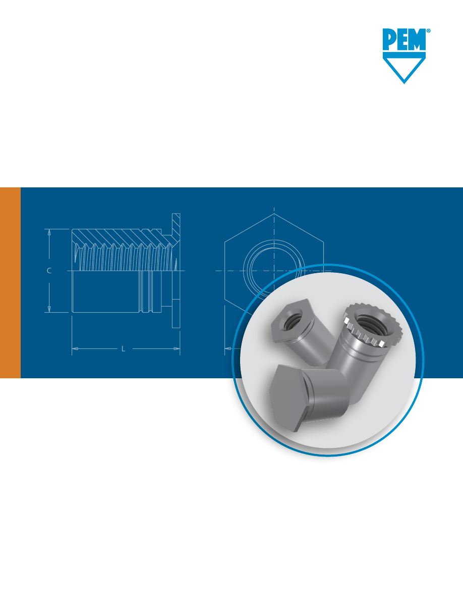
background image

SO


SELF-CLINCHING  

STANDOFFS

PEM® through hole threaded and 
unthreaded standoffs for mounting, 
spacing or stacking panels.

penn/sodata-html.html
background image

Self-Clinching Standoffs

SO-2


PennEngineering • 

www.pemnet.com

 BSO


   • •

 BSOA


• 

•     

  •

 BSOS


 • 

• 

•     

  •

 BSO4


• 

(2)

 •  •

 DSO


          •      

 DSOS


 •     •     •

 SO


           •

 SOA


       • 

   •

 SOS


 •      • 

   •

 SO4


• 

(2)

         •

 SOAG


    •    

  •

 SOSG


• 

  •    

  •

 TSO


    • •


(3)

      •  •

 TSOA


    • •


(3)

      • • •

 TSOS


  •  • •


(3)

      • • •

 TSO4


• 

(2)

  • •


(3)

      •  •

PEM® self-clinching standoffs, which use the proven self-clinching design, provide ideal 

solutions for applications where mounting, spacing or stacking of panels, boards or 

components are required. Pressed into round holes, these fasteners mount permanently 

into metal sheets as thin as .025” / 0.63 mm.

Specially designed SO4™, BSO4™ and TSO4™ standoffs are made from hardened stainless 

steel and are ideal for clinching into stainless steel sheets. An optional nickel plating is 

now available if product is expected to be used in a corrosive environment.

For more information on the proper use of PEM® self-clinching standoffs, check our 

website for Tech Sheet 

PEM® - REF/Standoff Basics

.

Fastener drawings and models are available at 

www.pemnet.com.

Custom sizes are available on special order. 

Contact us

 for more information.

Blind  

Threads

Through-Hole 

Threads

Support 

This sheet

SO™/SOS™/SOA™/SO4™


through hole 

threaded

 self-clinching standoffs 

 — 

PAGE 3

BSO™/BSOS™/BSOA™/BSO4™


Blind hole, 

threaded

 self-clinching standoffs 

— 

PAGE 4

SO™/SOS™/SOA™/SO4™


Through hole, 

unthreaded

 self-clinching standoffs  

— 

PAGE 5

TSO™/TSOS™/TSOA™/TSO4™

 Through 

hole threaded standoffs 

for clinching into 

thinner sheets

 than SO™ standoffs — 

PAGE 6

DSOS™/DSO™

 Through hole, threaded 

standoffs with round, knurled head 

allowing 

closer-to-edge clinch installation

 — 

PAGE 7

SOSG™/SOAG™

 Through hole, threaded 

grounding standoffs with 

“grounding/

earthing teeth” on end of barre

l — 

PAGE 7

Material and finish specifications 

— 

PAGE 8

Installation 

— 

PAGE 8-11

Performance data 

— 

PAGE 12-13

Application Requires:

PEM®

Standoff

Type

(1) See note 5 on page 8 about installing fasteners into stainless steel sheets.       (2) When used with optional nickel plating.       (3) Style #3 only.

SO/SOS/SOA/SO4

TSO/TSOS/TSOA/TSO4 (Styles 1 & 2)

SOSG/SOAG

Head Side Of Sheet After Installation

BSO/BSOS/BSOA/BSO4

TSO/TSOS/TSOA/TSO4 (Style 3)

DSOS/DSO

  Installation 

Superior 


Closed-end 

Grounding/ 

Closest-to-edge 


Thinnest 

Most varied

  into stainless 

corrosion 

Threads at 

for flush 

earthing teeth 

distance 

Available 

minimum 

standard length  Non-magnetic

 steel 

(1) 

resistance 

barrel end 

appearance 

on barrel end 

mounting 

Unthreaded 

sheet 

increments

© 2023 PennEngineering.

penn/sodata-html.html
background image

Uni

fie

d

Me

tric

Uni

fie

d

Me

tric

Self-Clinching Standoffs

SO-3


PennEngineering • 

www.pemnet.com

  Min. 

Hole Size 


Min. Dist.

 Thread Sheet 

In Sheet  Counter- 

C H 

Hole C/L 

D

 Code 

Thickness 

+.003 

Bore Dia.  +.000 Nom. to Edge


±.010


-.000 ±.005 -.005   (1)

  440  .040  .166  .125 .165 .187 .23
  6440  .040  .213  .125 .212 .250 .27
  632  .040  .213  .156 .212 .250 .27
  8632  .050  .281  .156 .280 .312  .31
  832  .050  .281  .188 .280 .312  .31
  032  .050  .281  .203 .280 .312  .31


                                   Type

  Thread 

                       Fastener Material   Thread

  Size 

 Stainless      

Hardened 

Code

   Steel  Steel  Aluminum  Stainless Steel 


.125 .187 .250 .312  .375 .437 .500 .562 .625 .687 .750 .812  .875 .937 1.00 1.062

  .112-40 

SO 

SOS SOA 

SO4


440 

4 6 8 10 12 14 16 18 20 22 24 – – – – –

  (#4-40)    


6440

(2)

  .138-32 

SO SOS  SOA 

SO4


632 

4  6  8 10  12  14  16  18  20 22 24  26  28 30  32  34

  (#6-32)    


8632

(2)

  .164-32 

SO  SOS  SOA 

SO4 

832  4  6  8 10  12  14  16  18  20 22 24  26  28 30  32  34

  (#8-32)

  .190-32


SO  SOS  SOA 

SO4 

032  4  6  8 10  12  14  16  18  20 22 24  26  28 30  32  34

  (#10-32)
 

D Dimension ±.010


None .187  .312  .437

  Min. 


Min. Dist.

 Thread Sheet 

Hole Size Counter-  C 

H  Hole C/L 

D

 Code 

Thickness 

In Sheet  Bore Dia.  -0.13 

Nom. 

to Edge 

±0.25

     +0.08 ±0.13      (1)

  M3  1 

4.22  3.2  4.2 4.8  6

  3.5M3  1 

5.41  3.2  5.39 6.4  6.8

  M3.5  1 

5.41  3.9  5.39 6.4  6.8

  M4  1.27  7.14  4.8  7.12 7.9  8
  M5  1.27  7.14  5.35 7.12 7.9  8

(2)  Standoffs with thread codes 6440, 8632, and 3.5M3 have a thicker wall to provide more bearing surface for the mating component or panel reducing the chance of 

cracking or cutting into the board.

Please contact your local PEM® distributor for availability, minimum quantity, and pricing information.

All dimensions are in millimeters.

General Dimensional Data

All dimensions are in inches.


                                    Type  


  Thread 

                         Fastener Material   Thread

  Size x 

 Stainless    Hardened 

Code

 Pitch  Steel 

Steel 

Aluminum  Stainless Steel


M3 x 0.5 

SO 

SOS SOA  SO4

 M3 

3  4  6  8  10 12 14 16 18  –  –  –


       3.5M3

(2)

 M3.5 x 0.6 

SO 

SOS 

SOA 

SO4 

M3.5 

10 

12 

14 

16 

18 

20 

22 

25

 M4 x 0.7 

SO 

SOS 

SOA 

SO4 

M4 

10 

12 

14 

16 

18 

20 

22 

25

 M5 x 0.8 

SO 

SOS 

SOA 

SO4 

M5 

10 

12 

14 

16 

18 

20 

22 

25


D Dimension ±0.25


None 

8 11

Thread Size And Length Selection Data

All dimensions are in inches.

All dimensions are in millimeters.

Length “L” +.002 –.005 (Length Code in 32nds of an inch)

Length “L” +0.05 –0.13

(Length Code in millimeters)

SO™/SOS™/SOA™/SO4™ - Through-Hole Threaded Standoffs

SO 

  – 440 –  8 

ZI

SO  S  – 440 –  8

SO  A – 440 –  8

SO  4 – 440 –  8  NC*

Material

Code

Thread

Code

Length 

Code

Type

Finish

SO/SOS/SOA

SO4

Installs into stainless steel

Clinching profile may vary.

H

L

D

B

C

PEM® “Single” or PEM® “Two Groove” Registered Trademark

*  NC suffix is required if optional nickel plating (for corrosion 

resistance) is desired. Otherwise, no suffix is necessary.

•  SO standoffs are recommended for use in steel or aluminum sheets HRB (Rockwell “B” scale) 80 / HB (Hardness Brinell) 150 or less.

•  SOS standoffs are recommended for use in steel or aluminum sheets HRB (Rockwell “B” scale) 70 / HB (Hardness Brinell) 125 or less.

•  SOA standoffs are recommended for use in aluminum sheets HRB (Rockwell “B” scale) 50 / HB (Hardness Brinell) 82 or less.

•  SO4 standoffs are recommended for use in stainless steel sheets HRB (Rockwell “B” scale) 88 / HB (Hardness Brinell) 183 or less.

Micro sizes also available.

See PEM® 

Bulletin MPF

 for more information.

(1)   For more information on proximity to bends and distance to other clinch hardware, 

se

PEM® Tech Sheet C/L To Edge

.

Part Number Designation

Varies 

according 

to length.

See length 

charts 

below.

Varies 

according 

to length.

See length 

charts 

below.

penn/sodata-html.html
background image

Me

tric

Uni

fie

d

Uni

fie

d

Me

tric

Self-Clinching Standoffs

SO-4


PennEngineering • 

www.pemnet.com


                               Type  


 Thread 


Thread

  Size x 

 Stainless   

Hardened 

Code

 Pitch 

Steel 

Steel 

Aluminum 

Stainless Steel


M3 x 0.5 BSO  BSOS  BSOA 

BSO4


M3 

6  8  10  12  14  16  18  20  22 25


3.5M3

(2)

 M3.5 x 0.6 

BSO 

BSOS 

BSOA 

BSO4 

M3.5 

10 

12 

14 

16 

18 

20 

22 

25 

 M4 

x 0.7 

BSO 

BSOS 

BSOA 

BSO4 

M4 

10 

12 

14 

16 

18 

20 

22 

25

 M5 x 

0.8 

BSO 

BSOS 

BSOA BSO4 M5 

6 8 10 

12 

14 

16 18 

20 

22 

25


F Dimension Min.


3.2 4  5 6.5 

9.5

Thread Size And Length Selection Data

All dimensions are in inches.

All dimensions are in millimeters.

Length “L” +0.05 –0.13

(Length Code in millimeters)

BSO™/BSOS™/BSOA™/BSO4™ - Blind Threaded Standoffs


                         Type

  Thread      


Thread 

  Size 

 Stainless   

Hardened 

Code


Steel 

Steel 

Aluminum  Stainless Steel

    .312  .375  .437 .500  .562 .625 .687  .750  .812  .875 .937  1.00 1.062

  .112-40 

BSO 

BSOS BSOA  BSO4 

440 

10  12  14  16  18  20  22 24  26 28 30 32 34

 (#4-40) 


    6440

(2)

  .138-32 BSO  BSOS  BSOA 

BSO4 

632 

10  12  14  16  18  20  22 24  26 28 30 32 34

  (#6-32) 


8632

(1)

  .164-32 

BSO BSOS  BSOA 

BSO4 

832  10  12  14  16  18  20  22  24  26  28  30  32  34

  (#8-32)
  .190-32 

BSO BSOS  BSOA 

BSO4 

032  10  12  14  16  18  20  22  24  26  28  30  32  34

  (#10-32)
 

F Dimension Min.


.156 .187 

.250 

.375

BSO   – 440 – 12 

ZI

BSO 

S – 440 – 12

BSO 

A – 440 – 12

BSO 

4 – 440 – 12  NC*

PART NUMBER DESIGNATION

Material

Code

Thread

Code

Length 

Code

Type

Finish

Length “L” +.002 –.005 (Length Code in 32nds of an inch)

BSO/BSOS/BSOA

PEM® “Single” or PEM® “Two Groove” Registered Trademark

Clinching profile may vary.

H

C

F

L

BSO4

Installs into stainless steel

(2)  Standoffs with thread codes 6440, 8632, and 3.5M3 have a thicker wall to provide more bearing surface for the mating component or panel reducing the chance of 

cracking or cutting into the board.

Please contact your local PEM® distributor for availability, minimum quantity, and pricing information.

*  NC suffix is required if optional nickel plating (for corrosion resistance) is desired.  

Otherwise, no suffix is necessary.

•  BSO standoffs are recommended for use in steel or aluminum sheets HRB (Rockwell “B” scale) 80 / HB (Hardness Brinell) 150 or less.

•  BSOS standoffs are recommended for use in steel or aluminum sheets HRB (Rockwell “B” scale) 70 / HB (Hardness Brinell) 125 or less.

•  BSOA standoffs are recommended for use in aluminum sheets HRB (Rockwell “B” scale) 50 / HB (Hardness Brinell) 82 or less.

•  BSO4 standoffs are recommended for use in stainless steel sheets HRB (Rockwell “B” scale) 88 / HB (Hardness Brinell) 183 or less.

   Min. 

Hole Size 


Min. Dist.

 Thread  Sheet 

In Sheet 

Hole C/L 

F

 Code Thickness +.003 

+.000  Nom. 

to Edge 

Min.

     -.000 -.005  

(1)

  440  .040  .166  .165 .187 

.23

  6440  .040  .213 

.212 .250 

.27

  632  .040  .213 

.212 .250 

.27

  8632  .050  .281  .280 .312 

.31

  832  .050  .281  .280 .312 

.31

  032  .050  .281  .280 .312 

.31


Min. 

Hole Size 


Min. Dist.


Thread 

Sheet 

In Sheet 

C H 

Hole C/L 

F


Code Thickness  +0.08  -0.13 Nom.  to Edge (1) 

Min.

 M3  1  4.22  4.2 4.8  6
 3.5M3  1 

5.41  5.39  6.4  6.8

 M3.5  1 

5.41  5.39 6.4  6.8

 M4  1.27  7.14  7.12 7.9  8


M5  1.27  7.14  7.12 7.9  8

All dimensions are in millimeters.

General Dimensional Data

All dimensions are in inches.

Varies 

according 

to length.

See length 

charts 

below.

(1)   For more information on proximity to bends and distance to other clinch hardware, 

see 

PEM® Tech Sheet C/L To Edge

.

Varies 

according 

to length.

See length 

charts 

below.

penn/sodata-html.html
background image

Uni

fie

d

Me

tric

Uni

fie

d

Me

tric

Self-Clinching Standoffs

SO-5


PennEngineering • 

www.pemnet.com

   Min. 

Hole Size 


Min. Dist.

 Thru-hole  Sheet 

In Sheet 

Hole C/L

 Code Thickness +.003 

+.000 

Nom. 

to Edge

     -.000 

-.005   (1)

 4116  .040  .166  .165  .187  .23
 6116  .040  .213  .212  .250  .27
 6143  .040  .213  .212  .250  .27
 8143  .050  .281  .280  .312  .31
 8169  .050  .281  .280  .312  .31
 8194  .050  .281  .280  .312  .31


Min. 

Hole Size 


Min. Dist.


Thru-hole 

Sheet 

In Sheet 

C H 

Hole C/L

  Code  Thickness +0.08  -0.13 Nom. 

to Edge (1)

 43.1  1  4.22  4.2  4.8  6
 63.1  1  5.41  5.39  6.4  6.8
 63.6  1  5.41  5.39  6.4  6.8
 83.6  1.27  7.14  7.12  7.9  8
 84.1  1.27  7.14  7.12  7.9  8
 85.1  1.27  7.14  7.12  7.9  8


                             Type

  Thru-hole

  Diameter 

 Stainless   

Hardened Thru-hole

  +0.1 -0.08  Steel  Steel  Aluminum  Stainless Steel Code


3.1      

SO4

 43.1 

3 4 6 8 10 12 14 16 18 20

   S0 SOS  SOA  63.1

(1) 


3.6  SO SOS  SOA 

SO4


63.6 

3 4 6 8 10 12 14 16 18 20


83.6

(1)


4.1 

SO 

SOS SOA  SO4  84.1 3 4 6 8 10 12 14 16 18 20


5.1 

SO 

SOS SOA  SO4  85.1 3 4 6 8 10 12 14 16 18 20


                             Type

  Thru-hole    


  Diameter 

 Stainless   

Hardened Thru-hole

 +.004 -.003  Steel  Steel  Aluminum  Stainless Steel Code  .125  .187  .250  .312  .375  .437  .500  .562  .625  .687  .750


.116  SO SOS  SOA 

SO4

 4116 

4  6  8  10 12  14  16  18 20 22 24


6116

(2)

  .143 SO SOS  SOA  SO4 

6143 

4  6  8  10 12  14  16  18 20 22 24


8143

(2)

  .169  SO SOS  SOA 

SO4 

8169  4  6  8  10  12  14  16  18  20  22  24

  .194  SO SOS  SOA 

SO4 

8194  4  6  8  10 12  14  16  18 20 22 24

All dimensions are in millimeters.

General Dimensional Data

All dimensions are in inches.

Through-Hole And Length Selection Data

All dimensions are in inches.

All dimensions are in millimeters.

SO™/SOS™/SOA™/SO4™ - Through-Hole Unthreaded Standoffs (Special Order) 

Length “L” +.002 –.005 (Length Code in 32nds of an inch)

Length “L” +0.05 –0.13

(Length Code in millimeters)

SO 

  – 4116 –  8 

ZI

SO  S  – 4116 –  8

SO  A – 4116 –  8

SO  4 – 4116 –  8  NC*

Part Number Designation

Material

Code

Thru-hole

Code

Length 

Code

Type

Finish

SO/SOS/SOA

SO4

Installs into stainless steel

(2)  Standoffs with thru-hole codes 6116, 8143, 63.1 and 83.6 have a thicker wall to provide more bearing surface for the mating component or panel reducing the chance of 

cracking or cutting into the board.

Please contact your local PEM® distributor for availability, minimum quantity, and pricing information.

*  NC suffix is required if optional nickel plating (for corrosion resistance) is desired. 

Otherwise, no suffix is necessary.

H

L

C B

Clinching profile may vary.

PEM® “Single” or PEM® “Two Groove” Registered Trademark

Micro sizes also available.

See PEM® 

Bulletin MPF

 for more information.

•  SO standoffs are recommended for use in steel or aluminum sheets HRB (Rockwell “B” scale) 80 / HB (Hardness Brinell) 150 or less.

•  SOS standoffs are recommended for use in steel or aluminum sheets HRB (Rockwell “B” scale) 70 / HB (Hardness Brinell) 125 or less.

•  SOA standoffs are recommended for use in aluminum sheets HRB (Rockwell “B” scale) 50 / HB (Hardness Brinell) 82 or less.

•  SO4 standoffs are recommended for use in stainless steel sheets HRB (Rockwell “B” scale) 88 / HB (Hardness Brinell) 183 or less.

(1)   For more information on proximity to bends and distance to other clinch hardware, 

se

PEM® Tech Sheet C/L To Edge

.

penn/sodata-html.html
background image

Uni

fie

d

Uni

fie

d

Me

tric

Me

tric

Uni

fie

d

Me

tric

Self-Clinching Standoffs

SO-6


PennEngineering • 

www.pemnet.com

  Thread 

Length “L” 

Length “L” 

Length “L”


Code 

(Style #1) 

(Style #2) 

(Style #3)

  256 / 6256  .090 - .250 

.251 - .375 

.376 - .750

  440 / 6440  .090 - .280 

.281 - .450 

.451 - .750


632 

.120 - .350 

.351 - .540 

.541 - .750

  Thread 

Length “L” 

Length “L” 

Length “L”


Code 

(Style #1) 

(Style #2) 

(Style #3)

  M25 / 6M25 

2.00 - 6.30 

6.32 - 9.50 

9.52 - 19.00

  M3 / 6M3 

2.00 - 7.50 

7.52 - 11.00 

11.02 - 19.00


M35 

3.00 - 8.80 

8.82 - 12.80 

12.82 - 19.00

Thread Size And Length Selection Data

All dimensions are in inches.

All dimensions are in millimeters.

LENGTH/STYLE DATA

All dimensions are in inches.

(Length can be specified in .001” increments.)

All dimensions are in millimeters.

(Length can be specified in 0.02 mm increments.)

TSO™/TSOS™/TSOA™/TSO4™ Threaded Standoffs For Sheets As Thin As .025”/0.63mm

(1) Style #1. Thru-threaded.

(2) Style #2. Screw might not pass through unthreaded end. Tapped to minimum full thread depth shown. Incomplete threads on tap may allow screw to pass through.

(3) Style #3. Blind.

(4) Standoffs with thread codes 6256, 6440, 6M25 and 6M3 have a thicker wall to provide more bearing

surface for the mating component or panel reducing the chance of cracking or cutting into the board.
Please contact your local PEM® distributor for availability, minimum quantity, and pricing information.


Min. 

Hole Size 

F Min. 


Min. Dist.


Thread 

Sheet 

In Sheet 

+.000 

Thread 

Hole C/L


Code 

Thickness  +.003 -.000 

-.005 

Depth 

Nom.  to Edge (5)

 256 .025  .166  .165 

.200

 .187  .23

 6256 .025  .213  .212    .250 .27
 440 .025  .166  .165 

.220

 .187  .23

 6440 .025  .213  .212    .250 .27
  632  .025  .213  .212 .270 .250  .27


Min. 

Hole Size 


F Min. 


Min. Dist.


Thread 

Sheet 

In Sheet 

Thread 

Hole C/L


Code 

Thickness 

+0.08 

-0.13 

Depth 

Nom. 

to Edge (5)

  M25 0.63  4.22  4.2 

5.2

 4.8  5.8

  6M25 0.63  5.41  5.39    6.4  7.1
  M3 0.63  4.22  4.2 

6.2

 4.8  5.8


6M3 0.63  5.41  5.39    6.4  7.1

  M35 0.63  5.41  5.39 7  6.4  7.1

All dimensions are in millimeters.

General Dimensional Data

All dimensions are in inches.

  Thread 

                      Type

  Size x 


Hardened  Thread

 Pitch 

  Stainless 


Stainless  Code  2.00 3.00 4.00  6.00  8.00  10.00 12.00 14.00  16.00  18.00  19.00

   Steel Steel Aluminum  Steel 


 Length Code (Length “L” without decimal point)

  M2.5 x 0.45 TSO  TSOS  TSOA  TSO4 

M25 200

(1)

 300

(1)

 400

(1)

 600

(1)

 800

(2)

 1000

(3)

 1200

(3)

 1400

(3)

 1600

(3)

 1800

(3)

 1900

(3)


6M25

(4)

  M3 x 0.5 TSO  TSOS  TSOA  TSO4  M3 200

(1)

 300

(1)

 400

(1)

 600

(1)

 800

(2)

 1000

(2)

 1200

(3)

 1400

(3)

 1600

(3)

 1800

(3)

 1900

(3)


6M3

(4)

  M3.5 x 0.6 TSO  TSOS  TSOA 

TSO4  M35


– 300

(1)

 400

(1)

 600

(1)

 800

(1)

 1000

(2)

 1200

(2)

 1400

(3)

 1600

(3)

 1800

(3)

 1900

(3)

Length “L” ±0.08

For other lengths / thread depth data see chart at bottom of page.


                     Type


 Hardened 

 Thread 


Stainless  Stainless Thread  .090  .125  .187  .250  .312  .375  .437  .500  .562  .625  .687  .750


Size 

Steel Steel Aluminum  Steel Code 


     Length Code (Length “L” without decimal point)

  .086-56 

TSO TSOS  TSOA  TSO4


256 

090

(1)

 125

(1)

 187

(1)

 250

(1)

 312

(2)

 375

(2)

 437

(3)

 500

(3)

 562

(3)

 625

(3)

 687

(3)

 750

(3)

  (#2-56)    


 6256

(4)

 .112-40 

TSO TSOS  TSOA  TSO4

 440 

090

(1)

 125

(1)

 187

(1)

 250

(1)

 312

(2)

 375

(2)

 437

(2)

 500

(3)

 562

(3)

 625

(3)

 687

(3)

 750

(3)

  (#4-40)    


 6440

(4)

  .138-32 

TSO TSOS  TSOA  TSO4  632  –  125

(1)

 187

(1)

 250

(1)

 312

(1)

 375

(2)

 437

(2)

 500

(2)

 562

(3)

 625

(3)

 687

(3)

 750

(3)

  (#6-32)

Length “L” ±.003

For other lengths / thread depth data see chart at bottom of page.

*  NC suffix is required if optional nickel 

plating (for corrosion resistance) is 

desired. Otherwise, no suffix is necessary.

TSO 

  –  440 – 250  ZI

TSO  S  –  440 – 250

TSO  A  –  440 – 250

TSO  4  –  440 – 250  NC*

Part Number Designation

Material

Code

Thread

Code

Length 

Code

Type

Finish

•  TSO standoffs are recommended for use in steel or aluminum sheets HRB (Rockwell “B” scale) 60 / HB (Hardness Brinell) 107 or less.

•  TSOS standoffs are recommended for use in steel or aluminum sheets HRB (Rockwell “B” scale) 70 / HB (Hardness Brinell) 125 or less.

•  TSOA standoffs are recommended for use in aluminum sheets HRB (Rockwell “B” scale) 50 / HB (Hardness Brinell) 82 or less.

•  TSO4 standoffs are recommended for use in stainless steel sheets HRB (Rockwell “B” scale) 88 / HB (Hardness Brinell) 183 or less.

(5)  For more information on proximity to bends and distance to other clinch 

hardware, see 

PEM® Tech Sheet C/L To Edge

.

C

F

H

L

Style #3

TSO/TSOS/TSOA

TSO4

Installs into 

stainless steel

Style #1

C

L

Clinching profile may vary.

Style #2

C

F

L

PEM® “Single” or PEM® “Two Groove” 

Registered Trademark

penn/sodata-html.html
background image

Uni

fie

d

Me

tric

Uni

fie

d

Me

tric

Self-Clinching Standoffs

SO-7


PennEngineering • 

www.pemnet.com


Type 


Hole Size 


Min. Dist.

 Thread 

Stainless 


Thread 

Length 

Sheet 

In Sheet 

+.002 -.005 

Hole C/L

 Size 

Steel  Steel 

Code 

Code 

Thickness 

+.003 -.000 

Max. 

Nom. 

(1) 

to Edge (2)


.112-40 

DSOS   DSO 

440

 250 

.037 - .250 

.166 

.165 

.194

 .250 

.126


(#4-40) 


275 


.275


Thread 


Type 


Hole Size 

C  L 

Min. Dist.


Size x 

Stainless 


Thread 

Length 

Sheet 

In Sheet 

Max. 

+0.05 -0.13 

Hole C/L

 Pitch 

Steel  Steel  Code  Code  Thickness +0.08 


Nom.  (1)  to Edge (2)


M3 x 0.5 

DSOS 


DSO 

M3

 6.35 

0.94 - 6.35 

4.22 

4.2 

4.92

 6.35 

3.2


7     7

(1) Available in other lengths on special order.

(2) For more information on proximity to bends and distance to other clinch hardware, see 

PEM® Tech Sheet C/L To Edge

.

All dimensions are in inches.

All dimensions are in millimeters.

DSOS™/DSO™ Threaded Standoffs - For Close-To-Edge Applications


              Min. Hole

  Thread                   

Type  

Thread 


Sheet 

Size In 

Min. Dist.

  Size    Code        Thick- Sheet +.000 ±.005 

Nom. 

Hole C/L

L

   Stainless  

  .125  .187  .250  .312 .375  .437 .500 

ness +.003 –.005   

  to Edge

   Steel 

Aluminum 

           –.000     (2)

  .112-40 

SOSG 

SOAG 

6440 4  6  8  10 12  14 16 .040 .213 .212 .250 .030 .27

  (#4-40)
  .138-32 SOSG  SOAG  8632  4  6  8  10  12  14  16  .050  .281  .280  .312  .030  .31

  (#6-32)

  Thread 


Min. 

Hole 


Min. Dist.

  Size x 

Type


Thread 


Sheet 

Size In 

Hole C/L

  Pitch  Stainless 


Code 


Thick- 

Sheet 

–0.13 

±0.25 

Nom. 

to Edge   


Steel 

Aluminum 


ness 

+0.08 

   (2) 

  M3 x 0.5 

SOSG 

SOAG 

3.5M3 

10 

12 

5.4 

5.39 

6.4 

0.76 

6.8

SOSG™/SOAG™ Grounding/Earthing Standoffs

All dimensions are in inches.

All dimensions are in millimeters.

Metal

PC Board

or plastic

DSO  S  –  440 – 250

DSO    –  440 – 250  ZI

Part Number Designation

Material

Code

Thread

Code

Length 

Code

Type

Finish

SO  S 

G  – 6440 – 10

SO  A 

G  – 6440 – 10

Part Number Designation

Material

Code

Thread

Code

Length 

Code

Type

Grounding/

Earthing

Length “L” +0.25


(Length Code is in millimeters)


Length “L” +.010 -.000

(Length Code is in 32nds of an inch)

Clinching profile may vary.

C

L

H

PEM® “Two Groove” Registered Trademark

Clinching profile may vary.

H

L

P

C

Grounding/

earthing 

Teeth

PEM® “Two Groove”

Registered Trademark

•  DSO standoffs are recommended for use in steel or aluminum sheets HRB (Rockwell “B” scale) 80 / HB (Hardness Brinell) 150 or less.

•  DSOS standoffs are recommended for use in steel or aluminum sheets HRB (Rockwell “B” scale) 70 / HB (Hardness Brinell) 125 or less.

Please contact your local PEM® distributor for availability, minimum quantity, and pricing information.

(2) For more information on proximity to bends and distance to other clinch hardware, see 

PEM® Tech Sheet C/L To Edge

.

penn/sodata-html.html
background image

Self-Clinching Standoffs

SO-8


PennEngineering • 

www.pemnet.com


Threads 

(1)


Fastener Materials 

Standard Finishes 

Optional Finish 

For Use In Sheet Hardness:  

(4)


Internal, ASME 


Non-heat 


300 

Hardened 

Zinc Plated 

Passivated 


Electroless Nickel


B1.1, 2B 

Hardened  Treated 


Series 

400 Series 

per ASTM B633,  and/or Tested 


over Copper over 

HRB 88 /  HRB 80 /  HRB 70 /  HRB 60 /  HRB 50 /

  Type 

ASME 

Carbon 

Carbon  Aluminum  Stainless  Stainless Steel  SC1 (5µm),  Type III  Per ASTM 

No 

Nickel Strike 

HB 183 

HB 150 

HB 125 

HB 107 

HB 82

   B1.13M, 6H 

Steel 

Steel 


Steel 

(5) 

Colorless (2) 

A380 

Finish  Per ASTM B733 (2) (3)  or Less 

or Less 

or Less 

or Less 

or Less


SO 

•  •      

• 


 •

 SOA 

•    •    


 •   

       •

 SOS 

•        •   


•  


    •

 SO4 

•       • 


•   • 

 BSO 

•  •      

• 


 •

 BSOA 

•    •    


 •   

       •

 BSOS 

•        •   


•  


    •

 BSO4 

•       • 


•   • 

 TSO 

•   •      

• 


     •

 TSOS 

•        •   


•  


    •

 TSOA 

•    •    


 •   

       •

 TSO4 

•       • 


•   • 

 DSO 

•  •      

• 


 •

 DSOS 

•        •   


•  


    •

 SOAG 

•    •    


 •   

       •

 SOSG 

•        •   


•  


    •


 Part Number Codes For Finishes 


ZI 

None 

None 

NC

SO™/SOS™/SOA™/SO4™/BSO™/BSOS™/BSOA™/BSO4™ Standoffs

1.  Prepare properly sized mounting hole in sheet. Do not perform any secondary 

operation such as deburring.

2.  Insert standoff through mounting hole (preferably the punch side) of sheet and 

into anvil as shown in drawing.

3.   With installation punch and anvil surfaces parallel, apply only enough squeezing 

force to embed the standoff’s head flush in the sheet. Drawing at right shows 

suggested tooling for applying these forces.

C*

L* Min.

PUNCH

+.004” to +.007” /

+0.1 mm  to +0.18 mm

ANVIL

Installation

(1)  Where applicable.

(2)  See PEM Technical Support section of our website for related plating standards and specifications.

(3)  Not stocked, available on special order. Minimum quantities apply. Contact your local PEM® distributor for details.

(4)  HRB - Hardness Rockwell “B” Scale. HB - Hardness Brinell.

(5)  In order for self-clinching fasteners to work properly, the fastener must be harder than the sheet into which it is being installed (For more information, see our 

tech sheet

 for installing fasteners into stainless steel sheets). In the case of stainless steel panels, fasteners made from 300 Series Stainless Steel do not meet 

this hardness criteria.  It is for this reason that SO4™, BSO4™ and TSO4™ 400 series fasteners are offered.  However, while these 400 Series fasteners install and 

perform well in 300 Series stainless sheets they should not be used if the end product will be exposed to any appreciable corrosive environment (unless finished 

with optional nickel plating), requires non-magnetic fasteners or will be exposed to any temperatures above 300˚F (149˚C). If any of the these are issues, please 

contact 

techsupport@pemnet.com

 for other options.

Material And Finish Specifications

Installation Tooling

*

See page 3 & 4


for “C” and “L”.


Thread 

HAEGER® Part No. 

PEMSERTER® Part Number

 Code 

Anvil Punch Anvil Punch

 440/M2/M2.5/M3 

H-109-4/M3L  H-108-0020L  970200487300  975200048

 632/6440/3.5M3/M3.5  H-109-6/M3.5L 

H-108-0020L 

970200012300 

975200048

 832/8632/032/M4/M5  H-109-8-10/M5L 

H-108-0020L 

970200013300 

975200048

  0420/M6 

H-109-04/M6L  H-108-0020L 970200393300 975200048

penn/sodata-html.html
background image

Uni

fie

d

Me

tric

Self-Clinching Standoffs

SO-9


PennEngineering • 

www.pemnet.com

Required Installation Anvil For 

Sheets Below .032” / 0.81 mm

L* Min.

B

120˚

PUNCH

ANVIL

TSO™/TSOS™/TSOA™/TSO4™ Standoffs

1.  Prepare properly sized mounting hole in sheet. Do not perform any 

secondary operation such as deburring.

2.  Insert standoff through mounting hole (preferably the punch side) of 

sheet and into anvil as shown in drawing.

3.   With installation punch and anvil surfaces parallel, apply only enough 

squeezing force to embed the standoff’s head flush in the sheet. 

Drawing at right shows required installation anvil for sheet thickness of 

.025” to .032” / 0.63 mm to 0.81 mm. A chamfered anvil is not required 

for sheets over .032” / 0.81 mm.

Installation


HAEGER® Part Numbers 

PEMSERTER® Part Numbers


Anvil       Anvil 


Thread 


For sheets 


For Sheets 

 Code 

B Anvil 

Over .032” 

Punch


B Anvil 

Over .032” 

Punch

 256/440 

(1) 

(1) 

H-109-4/M3L H-108-0020L 

.187 - .194 

8003291 

970200487300 

975200048

 6256/6440/632 

(1) 

(1) 

H-109-6/M3.5L H-108-0020L 

.250 - .257 

8003292 

970200012300 

975200048

Installation Tooling

C*

Anvil Dimensions (in.)

For Sheets Below .032”

+.001” to +.004” /

+0.03 mm  to +0.1 mm

*

See page 6

 for “C” 

and “L”.

(1) 

Click here

 for a quote on Haeger® custom anvil installation tooling.

Anvil Dimensions (in.)

For Sheets Below .032”


HAEGER® Part Numbers 

PEMSERTER® Part Numbers


Anvil       Anvil 


Thread 


For sheets 


For Sheets 

 Code 

B Anvil 

Over 0.81 mm 

Punch


B Anvil 

Over 0.81 mm 

Punch

 M2.5/M3 

(1) 

(1) 

H-109-4/M3L H-108-0020L 

4.75 - 4.93 

8003291 

970200487300 

975200048

 6M25/6M3/M35 

(1) 

(1) 

H-109-6/M3.5L H-108-0020L 

6.35 - 6.53 

8003292 

970200012300 

975200048

Anvil Dimensions (mm)

For Sheets Below 0.81 mm

Anvil Dimensions (mm)

For Sheets Below 0.81 mm

penn/sodata-html.html
background image

Self-Clinching Standoffs

SO-10


PennEngineering • 

www.pemnet.com

DSOS™/DSO™ Standoffs

1.  Prepare properly sized mounting hole in sheet. Do not perform any secondary 

operations such as deburring.

2.  Insert fastener through mounting hole (preferably the punch side) and into anvil 

as shown in drawing.

3.   With installation punch and anvil surfaces parallel, apply only enough squeezing 

force to embed the standoff’s head flush in the sheet.

ANVIL

L* Min.

PUNCH

*

See page 7

 for 

“D” and “L”.

Installation Tooling

C*

PUNCH

ANVIL

+.004” to +.007” /

+0.1 mm  to +0.18 mm

*

See page 7

 for  

“C” and “L”.

SOSG™/SOAG™ Standoffs

1.  Prepare properly sized mounting hole in sheet. Do not perform any secondary 

operations such as deburring.

2.  Insert fastener through mounting hole (preferably the punch side) and into anvil 

as shown in drawing.

3.   With installation punch and anvil surfaces parallel, apply only enough squeezing 

force to embed the standoff’s head flush in the sheet.

PEMSERTER® Installation Tooling

C*

+.004” to +.007” /

+0.1 mm  to +0.18 mm

L* Min.

Installation Notes

•  For best results we recommend using a Haeger® or PEMSERTER® press for installation of 

PEM® standoffs. Please check our website for more information.

•  Visit the Animation Library on our website to view the installation process 

for this product

.


Thread 

HAEGER® Part No. 

PEMSERTER® Part Number

 Code 

Anvil Punch  Anvil Punch

 440/M3 

H-109-4/M3L  H-108-0020L  970200487300  975200048

 6440/3.5M3 

H-109-6/M3.5L 

H-108-0020L 

970200012300 

975200048


8632 

H-109-8-10/M5L 

H-108-0020L  

970200013300 

975200048


Thread 

HAEGER® Part No. 

PEMSERTER® Part Number

 Code 

Anvil Punch  Anvil Punch

 440/M3 

H-109-4/M3L  H-108-0020L  970200487300  975200048

 6440/3.5M3 

H-109-6/M3.5L 

H-108-0020L 

970200012300 

975200048


8632 

H-109-8-10/M5L 

H-108-0020L  

970200013300 

975200048

penn/sodata-html.html
background image

Self-Clinching Standoffs

SO-11


PennEngineering • 

www.pemnet.com

For Additional HAEGER® and PEMSERTER® Tooling Information / Part Numbers

Or download the  

HAEGER WIZZARD

 Phone App

Go t

haeger.com

 to access  

the Auto and Manual Tooling Wizards

} }

HAEGER® MANUAL TOOLING CATALOG

PEMSERTER® MANUAL TOOLING CATALOG

HAEGER® AUTO TOOLING CATALOG

PEMSERTER® AUTO TOOLING CATALOG

penn/sodata-html.html
background image

Uni

fie

d

Uni

fie

d

Me

tric

Me

tric

Self-Clinching Standoffs

SO-12


PennEngineering • 

www.pemnet.com


Max. Rec. 

Test Sheet Material (2)


Thread Standoff Tightening 

.060” 5052-H34 Aluminum 

.060” Cold-rolled Steel


Code Material 

Torque For


Mating Screw 

Installation 

Pushout 

Torque-out (3) Pull-thru 

(3) Installation  Pushout Torque-out 

(3) Pull-thru 

(3)


(in. lbs.) 

(lbs.) 

(lbs.) 

(in. lbs.) 

(lbs.) 

(lbs.) 

(lbs.) 

(in. lbs.) 

(lbs.)

   Steel  4.75  1100  160  11  280  2200 225  19  330
 

440 

Stainless Steel 

3.8 

1100 

160 

11 

224 

2200 

225 

19 

264


Aluminum 

2.85 

1100 

160 11 168 – – – –

    Steel  4.75  1700 300  25  310  3300 420  35  380
 

6440 

Stainless Steel 

3.8 

1700 

300 

25 

248 

3300 

420 

35 

304


Aluminum 

2.85 

1700 

300 

25 

186 – – – –

    Steel  8.75  1700 300  25  310  3300 420  35  380
 

632 

Stainless Steel 

1700 

300 

25 

248 

3300 

420 

35 

304


Aluminum 

5.25 

1700 

300 

25 

186 – – – –

    Steel  8.75  2400 400  45  580  4000 560  75  700
 

8632 

Stainless Steel 

2400 

400 

45 

464 

4000 

560 

75 

560


Aluminum 

5.25 

2400 

400 

45 

248 – – – –

    Steel  18  2400 400  45  580  4000 560  75  700
 

832 

Stainless Steel 

14.4 

2400 

400 

45 

464 

4000 

560 

75 

560


Aluminum 

11 

2400 

400 

45 

348 – – – –

    Steel  32  2400 400  45  580  4000 560  75  700
 

032 

Stainless Steel 

25.6 

2400 

400 

45 

464 

4000 

560 

75 

560


Aluminum 

19 

2400 

400 

45 

348 – – – –


Max. Rec. 

Test Sheet Material (2)


Thread Standoff Tightening 

1.5 mm 5052-H34 Aluminum 

1.5 mm Cold-rolled Steel


Code Material 

Torque For


Mating Screw 

Installation 

Pushout 

Torque-out (3) Pull-thru 

(3) Installation  Pushout  Torque-out 

(3) Pull-thru 

(3)


  (N•m) (kN)  (N) (N•m) (N)  (kN)  (N) (N•m) (N)

   Steel 0.55  4.9  710  1.24 1245  9.8 1000 2.15 1465
 

M3 

Stainless Steel 

0.44 

4.9 

710 

1.24 

996 

9.8 

1000 

2.15 

1172

    Aluminum 0.33  4.9  710  1.24  747 

– – – –

   Steel 0.55  7.6  1330 2.82 1375  14.7 1860 3.95 1690
 

3.5M3 

Stainless Steel 

0.44 

7.6 

1330 

2.82 

1100 

14.7 

1860 

3.95 

1352


Aluminum 

0.33 

7.6 

1330 

2.82 

825 – – – –

   Steel  0.91  7.6  1330 2.82 1375  14.7 1860 3.95 1690
 

M3.5 

Stainless Steel 

0.73 

7.6 

1330 

2.82 

1100 

14.7 

1860 

3.95 

1352


Aluminum 

0.55 

7.6 

1330 

2.82 

825 – – – –

   Steel  2  10.7 1780 5.08 2575  17.8 2490 8.47  3110
 

M4 

Stainless Steel 

1.6 

10.7 

1780 

5.08 

2060 

17.8 

2490 

8.47 

2488


Aluminum 

1.2 10.7 

1780 

5.08 

1545 – – – –

   Steel  3.6  10.7 1780 5.08 2575  17.8 2490 8.47  3110
 

M5 

Stainless Steel 

2.88 

10.7 

1780 

5.08 

2060 

17.8 

2490 

8.47 

2488


Aluminum 

2.16 

10.7 

1780 

5.08 

1545 – – – –

SO™/SOS™/SOA™/BSO™/BSOS™/BSOA™ Standoffs

(1)  Published installation forces are for general reference. Actual set-up and confirmation of complete installation should be made by observing proper seating of fastener 

as described in the installation steps. Other performance values reported are averages when all proper installation parameters and procedures are followed. Variations 

in mounting hole size, sheet material, and installation procedure may affect performance.  Performance testing this product in your application is recommended.  We will 

be happy to provide technical assistance and/or samples for this purpose.

(2)  See 

tech sheet

 on our website for performance data of PEM® Type SO™ standoffs installed into copper sheets.

(3)  Joint failure in torque-out and pull-thru will depend on the strength and type of screw being used. In some cases the failure will be in the screw and not in the self-

clinching standoff. Please contact our Applications Engineering group with any questions.

Performance Data

(1)


Max. Rec. 

Test Sheet Material


Thread 

Tightening 

.050” 300 Series Stainless Steel


Code 

Torque For


Mating Screw 

Installation 

Pushout 

Torque-out 

Pull-thru


(in. lbs.) 

(lbs.) 

(lbs.) 

(in. lbs.) (3) 

(lbs.) (3)

  440 

4.75  5500 336  17  600 

  6440  4.75  9500 647  30  680
  632 

8.75  9500 647  30  680


8632 

8.75 

10500 

900 

71 

1392  

  832 

18  10500 900  71  1517

  032 

32  10500 900  71  1368

SO4™/BSO4™ Standoffs


Max. Rec. 

Test Sheet Material


Thread 

Tightening 

1.3 mm 300 Series Stainless Steel


Code 

Torque For


Mating Screw 

Installation 

Pushout 

Torque-out 

Pull-thru


(N•m) 

(kN) 

(N) 

(N•m) (3) 

(N) (3)


M3 

0.55 

24.5 

1493 

2.36 

2650  

  3.5M3  0.55  42.3  2877  3.06 3025
  M3.5  0.91  42.3  2877  3.06 3025
 

M4 

46.7  4003  8.89 6458


M5 

3.6 

46.7  4003  8.89 6226

penn/sodata-html.html
background image

Uni

fie

d

Uni

fie

d

Me

tric

Me

tric

Self-Clinching Standoffs

SO-13


PennEngineering • 

www.pemnet.com

DSOS™/DSO™ Standoffs

(1)  Published installation forces are for general reference. Actual set-up and confirmation of complete installation should be made by observing proper seating 

of fastener as described in the installation steps. Other performance values reported are averages when all proper installation parameters and procedures 

are followed. Variations in mounting hole size, sheet material, and installation procedure may affect performance.  Performance testing this product in your 

application is recommended.  We will be happy to provide technical assistance and/or samples for this purpose.

(2)  Joint failure in torque-out and pull-thru will depend on the strength and type of screw being used. In some cases the failure will be in the screw and not in 

the self-clinching standoff. Please contact our Applications Engineering group with any questions.


Max. Rec. 


                                          Test Sheet Material

   Tightening 

                                           .040” 5052-H34 Aluminum 


                                           .040” Cold-rolled Steel


Thread 

Torque For 


Code 

Mating 

Screw 

Installation Pushout  Torque-out Pull-thru Installation Pushout Torque-out Pull-thru


(in. lbs.) 

(lbs.) 

(lbs.) 

(in. lbs.) (2) (lbs.) (2) 

(lbs.) 

(lbs.) 

(in. lbs.) (2) (lbs.) 

(2)


440 3.8  700 

50 

10 

320  1100 

75 

10 

357


Max. Rec. 


                                         Test Sheet Material

   Tightening 

                                           1 mm 5052-H34 Aluminum 


                                           1 mm Cold-rolled Steel


Thread 

Torque For 


Code 

Mating 

Screw 

Installation Pushout Torque-out Pull-thru Installation Pushout Torque-out Pull-thru


(N•m) 

(kN)  (N) (N•m) 

(2) (N) 

(2)  (kN)  (N) (N•m) 

(2) (N) (2)


M3 0.44  3.1 

223 

1.1 

1422 

4.9 

334 

1.1  1587

Performance Data

(1)


Thread 

Test Sheet Thickness and 

Installation 

Pushout 

Torque-out 

Pull-thru


Code 

 Test Sheet Material 

(lbs.) 

(lbs.) 

(in. lbs.) (2) (lbs.) (2)


6440 

.064” 5052-H34 Aluminum 1700 

300 

25 

186


8632 

.064” 5052-H34 Aluminum 1700 

400 

45 

248

SOSG™/SOAG™ Standoffs


Thread 

Test Sheet Thickness and 

Installation 

Pushout 

Torque-out 

Pull-thru


Code 

 Test Sheet Material 

(kN) 

(N) 

(N•m) (2) (N) (2)


3.5M3 

1.6 mm 5052-H34 Aluminum 

7.6 

1330 

2.82 

825


 Standoff “C” 

Standoff 

 Dimension 

Material 

Installation 

Pushout 

Torque-out (2) Pull-thru 

(2) Installation  Pushout  Torque-out 

(2) Pull-thru 

(2)


(lbs.)   (kN)  (lbs.)   (N)  (in. 

lbs.)  (N•m)  (lbs.)   (N) 

(lbs.)  (kN)  (lbs.)   (N)  (in. 

lbs.)  (N•m) 

  (lbs.)   (N)


  .165” / 

Steel 

700    3.1 

70    311 

6   0.68 

230  1022 

1100  4.9 

100  445 

9    1 

206  916

  4.2 mm  Stainless Steel  700    3.1 

70 


311 

  0.68 

268    1191 

1100    4.9 

100    445 


260    1155


Aluminum  700  3.1 

70  311 

6  0.68  227  1009 

—   — 

—   — 

—   — 

—   —

  .212” / 

Steel 

700    3.1 

90   400 

11    1.24 

264    1173 

1800   8 

150   667 

15    1.7 

207   920

  5.39 mm  Stainless Steel 

700   

3.1 

90 

  400 

11 

  1.24 

340    1511 

1800   

150    667 

15 


1.7 

344    1529


Aluminum  700  3.1 

90  400 

11  1.24 

300  1333 

—   — 

—   — 

—   — 

—   —

TSO™/TSOS™/TSOA™ Standoffs


Standoff “C”


Dimension 


Installation 


Pushout 


Torque-out 

(2)  

  Pull-thru 

(2)


(lbs.)    (kN)    (lbs.)    (N)   (in. 

lbs.)   (N•m) 

(lbs.)    (N)

  .165” / 4.2 mm 

6500 


28.9 


125 


555 


13 


1.5 

414 


1840

  .212” / 5.39 mm 

6800 


30.3 


160 


710 


22 


2.5 

552 


2453


Test Sheet Material

.025” / 0.64 mm 300 series stainless steel

TSO4™ Standoffs


Test Sheet Material


.025” / 0.64 mm 5052-H34 Aluminum 


.025” / 0.64 mm Cold-rolled Steel

penn/sodata-html.html
background image

Self-Clinching Standoffs

SO-14


PennEngineering • 

www.pemnet.com

If you require a standoff which we do not offer in this datasheet, please contact us. We will be happy to work with you to satisfy your 

special need. For other types of standard PEM® brand standoffs and spacers see:

PEM® “Single Groove”

(Registered trademark)

Parts that install into 

stainless steel sheets

PEM® “Two Groove”

(Registered trademark)

Due to differences in manufacturing methods, location 

of grooves and  surface appearance on barrel of actual 

parts may be different than shown in photo.

For more information on how to use

PEM® self-clinching standoffs, see Tech Sheet

PEM®-Ref/Standoff Basics

on our web site.

Fastener drawings and 

models are available at

www.pemnet.com

CH Datasheet

PEM® concealed-head standoffs.

SSA Datasheet

PEM® SNAP-TOP® standoffs.

SK Datasheet

PEM® KEYHOLE® standoffs.

K Datasheet

PEM® broaching and surface mount 

standoffs for printed circuit boards.

MPF Datasheet

microPEM® standoffs.

Custom sizes are available on special order. 

Contact us

 for more information.

penn/sodata-html.html
background image

Self-Clinching Standoffs

SO-15


PennEngineering • 

www.pemnet.com

penn/sodata-html.html
background image

2/19/24

SO-16


PennEngineering • 

www.pemnet.com

All PEM® products meet our stringent quality standards. If you require additional industry or other specific 

quality certifications

, special procedures and/or part numbers 

are required. Please contact your local sales office or representative for further information. 

Regulatory 

compliance information

 is available in Technical Support section of our website. Specifications subject to change without notice. See our website for the most 

current version of this bulletin.

North America: 

Danboro, Pennsylvania USA 

|

 E-mail

info@pemnet.com


|

 Tel: +1-215-766-8853 

|

 800-237-4736 (USA)

Europe:

 Galway, Ireland 

|

 E-mail: 

europe@pemnet.com


|

 Tel: +353-91-751714

Asia/Pacific: 

Singapore 

|

 E-mail

singapore@pemnet.com


|

 Tel: +65-6-745-0660

Shanghai, China:

 E-mail: 

china@pemnet.com


|

 Tel: +86-21-5868-3688

Visit our PEMNET™ Resource Center a

www.pemnet.com


 Technical support e-mail

techsupport@pemnet.com

Self-Clinching Standoffs