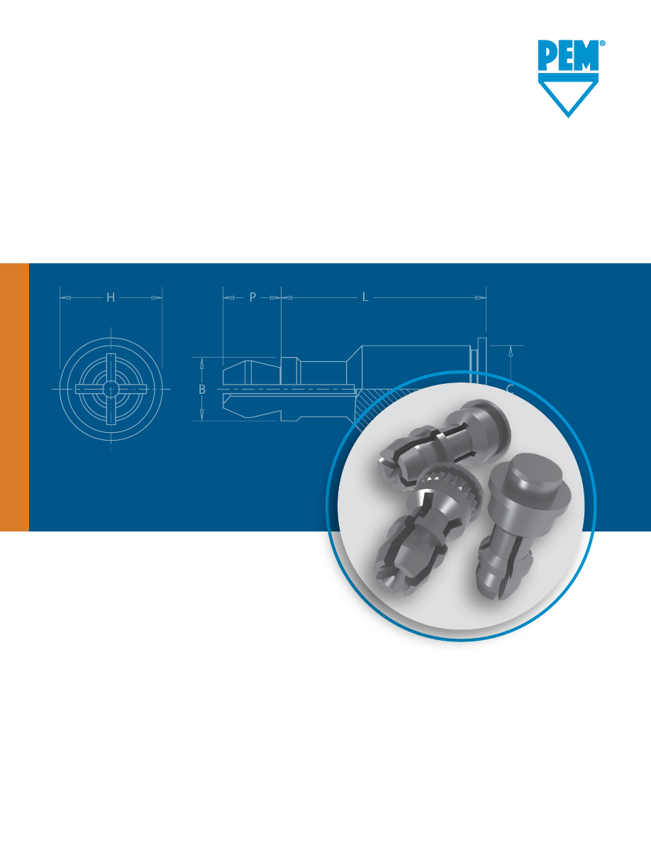
background image

SSA


SNAP-TOP®

STANDOFFS

PEM® brand SNAP-TOP® standoffs are 
designed for permanent installation 
into metal panels or PC Boards

penn/ssadata-html.html
background image

SNAP-TOP® Standoffs

SSA-2


PennEngineering • 

www.pemnet.com

To be sure that you are getting 

genuine PEM® brand SNAP-TOP® 

standoffs, look for the  

“dimple” registered trademark.

PC board or metal panel snapped in place

SSA™/SSS™/SSC™ standoffs 

clinched

 into a metal panel

PEM® SNAP-TOP® Standoffs are designed for permanent 

installation into metal panels or PC boards.

•  Spring action to hold PC Boards and subassemblies securely.

•  Allows for quick removal.

•  Eliminates screws and other threaded hardware.

  –  Less parts to handle during assembly.

  –  Less risk of damaging delicate circuitry because of  


  loose parts falling into your equipment.

•  Available in three different mounting styles:

  –  Self-clinching for installation into ductile materials

  –  Broaching for installation into PC Board and brittle material.

  –  Surface mount for installation to PC Board

•  Permanently installed in the panel.

Installation forces, pushout and snap forces are listed on 

page 8.

Fastener drawings and models are available at 

www.pemnet.com.

Custom sizes are available on special order. 

Contact us

 for mor

information.

KSSB™ standoffs 

broached

 into a PC board

PC board or metal panel snapped in place

SMTSSS™ standoffs 

surface mounted

 to PC Board

PC board or metal panel snapped in place

© 2023 PennEngineering.

Custom sizes are available on special order. 

Contact us

 for more information.

penn/ssadata-html.html
background image

Uni

fie

d

Me

tric

Uni

fie

d

Me

tric

SNAP-TOP® Standoffs

SSA-3


PennEngineering • 

www.pemnet.com

   Type


Fastener Material 

 Panel 

(Top)             B 

P


Aluminum Carbon  Stainless 

Mounting 

Hole 


±.005 

Max. 

±.005 

±.005


Steel Steel 

Diameter Code

  SSA SSS SSC 

156 

8  10  12  14  16  18  20  24  28 32 

(2)

  .188  .212 .250 .141

H

P

L

C

B

FASTENER MATERIAL: 

FINISH:

SSA: Aluminum 

SSA: Natural

SSS:  Carbon Steel 

SSS:  ZI - Zinc plated per ASTM B633, SC1 (5µm), Type III, colorless, plus clear chromate (1)

SSC:  400 Series Stainless Steel 

SSC:  Passivated and/or tested per ASTM A380


Type


Fastener Material 


Panel 

(Top) 

          B 

P


Aluminum Carbon  Stainless


Mounting 

Hole 


±0.13 

Max. 

±0.13 

±0.13


Steel Steel 

Diameter Code

  SSA SSS  SSC 

4MM 

8  10  12  14  16  18  20  22 25 

(2)

  4.78  5.39 6.35 3.58


Length Code “L” ±.005

(Length Code in 32nds of an inch)


Length Code “L” ±0.13

(Length Code in millimeters)

(1)  See PEM Technical Support section of our web site for related plating standards and specifications.

(2)  This length not available for Type SSA aluminum fasteners.

SS  A  - 156 - 10

SS  S  - 156 - 10 ZI

SS  C  - 156 - 10

Type

Part Number Designation

Mounting Hole A 

Diameter Code

Length

Code

Material

Finish

.250  .312 .375 .437 .500 .562 .625 .750 .875 1.00

SSA™/SSS™/SSC™ Standoffs For Clinching Into Metal Sheets

All dimensions are in inches.

All dimensions are in millimeters.

Mounting Hole A

Mounting Hole B

Location

Tolerance

Edge

C1

Edge

C2

PANEL 2 (TOP)

PANEL 1 (BOTTOM)


  Bottom   

Edge 

   Top    Edge

   Hardness 

Mounting  Panel Thickness Distance 

Location Hardness Mounting  Panel  Thickness 

Distance


Type 

Max. 

Hole B 

Material 

Min. 

C1 Min. 

Tolerance 

Max. 

Hole A 

Material 

Range 

C2  Min.


(2) 

+.003 -.000 


(4) 


+.003 -.000 


(3) 

(4)


SSA 

HRB 50 / HB 82 


PC Board


SSS 

HRB 60 / HB 107 

.213 

Metal .040  .260 ±.005 No Limit .156 or Metal 

.040 - .070 

.100


SSC 

HRB 70 / HB 125 


Panel 1

Panel 2


Bottom    Edge 

   Top    Edge

   Hardness 

Mounting  Panel  Thickness Distance 

Location Hardness Mounting  Panel  Thickness Distance


Type 

Max. 

Hole B 

Material 

Min. 

C1 Min. 

Tolerance 

Max. 

Hole A 

Material 

Range 

C2  Min.


(2)  +0.08   (4)    +0.08   (3) 

(4)


SSA 

HRB 50 / HB 82 


PC Board


SSS 

HRB 60 / HB 107 

5.41 

Metal 1  6.6 ±0.13 No Limit 4 or Metal 

1 - 1.8 

2.54


SSC 

HRB 70 / HB 125 


Panel 1

Panel 2

All dimensions are in inches.

All dimensions are in millimeters.

Application Data

(2)  HRB - Hardness Rockwell “B” Scale. HB - Hardness Brinell.

(3) Available for thicker boards on special order.

(4) For more information on proximity to bends and distance to other clinch hardware, see 

PEM® Tech Sheet C/L To Edge

.

penn/ssadata-html.html
background image

Uni

fie

d

Me

tric

Uni

fie

d

Me

tric

SNAP-TOP® Standoffs

SSA-4


PennEngineering • 

www.pemnet.com


Panel 2 (Top) 

          B C H P T


Type 

Mounting Hole 


±.005 

±.003 

±.005 

±.005 

±.005


Diameter Code


KSSB 156  8  10  12  14  16  18  20 24  28  32  .188  .226 .250  .141  .020


Panel 2 (Top) 

          B 

T


Type 

Mounting Hole 


±0.13 

±0.08 

±0.13 

±0.13 

±0.13


Diameter Code


KSSB 4MM 

8  10 

12 

14 

16 

18  20  22  25  4.78  5.74 6.35 3.58  0.51

FASTENER MATERIAL: 

FINISH:

Brass 

Standard:  X - Plain


Optional:  ET - Electro-plated Tin, ASTM B545 Class B (5µm) with preservative coating, annealed (1)


(Optional ET finish is available on special order with additional charge.)

H

P

L

T

C

B


Length Code “L” ±.005

(Length Code in 32nds of an inch)


Length Code “L” ±0.13

(Length Code in millimeters)

KSSB™ Standoffs For Broaching Into PC Boards

.250  .312 .375  .437 .500 .562  .625 .750  .875  1.00

(1)  See PEM Technical Support section of our web site for related plating standards and specifications.

KSS  B - 156 - 10  X

Type

Mounting Hole A 

Diameter Code

Length

Code

Material

Finish

All dimensions are in inches.

All dimensions are in millimeters.

(2)  HRB - Hardness Rockwell “B” Scale. HB - Hardness Brinell.

(3)  Available for thicker boards on special order.

(4)  For more information on proximity to bends and distance to other clinch hardware, se

PEM® Tech Sheet C/L To Edge

.


  Bottom     Edge 

   Top    Edge

   Hardness  Mounting  Panel  Thickness Distance 

Location Hardness Mounting  Panel  Thickness Distance


Type 

Max. 

Hole B 

Material 

Min. 

C1 Min. 

Tolerance 

Max. 

Hole A 

Material 

Range 

C2 Min.


(2) 

+.003 -.000 


(4) 


+.003 -.000 


(3) 

(4)


KSSB 

HRB 65 / HB 116 

.213 

PC Board .050  .220  ±.005  No Limit 

.156 

PC Board 

.040 - .070 

.100


or Metal

Panel 1

Panel 2


  Bottom     Edge 

   Top    Edge

   Hardness  Mounting  Panel  Thickness Distance 

Location Hardness Mounting  Panel  Thickness Distance


Type 

Max. 

Hole B 

Material 

Min. 

C1


Min. 

Tolerance 

Max. 

Hole A 

Material 

Range 

C2 Min.


(2) +0.08    (4)    +0.08   (3) 

(4)


KSSB 

HRB 65 / HB 116 

5.41 

PC Board 1.27  5.59  ±0.13  No Limit 4 PC Board 

1 - 1.8 

2.54


or Metal

Panel 1

Panel 2

All dimensions are in inches.

All dimensions are in millimeters.

Application Data

Mounting Hole A

Mounting Hole B

Location

Tolerance

Edge

C1

Edge

C2

PANEL 2 (TOP)

PANEL 1 (BOTTOM)

Part Number Designation

penn/ssadata-html.html
background image

Uni

fie

d

Me

tric

Uni

fie

d

Me

tric

SNAP-TOP® Standoffs

SSA-5


PennEngineering • 

www.pemnet.com

SMTSSS™ REELFAST® SNAP-TOP® Standoffs

ØH

ØD

Solder

Pad

Plated through 

hole not required.

Number Of Parts Per Reel

Packaged on 330 mm recyclable reels. Tape width is 24 mm.

Supplied with polyimide patch for vacuum pick up.

Reels conform to EIA-481.

E

P

L

A

C

B


Top 

Board 


  Min.      

ØH 

Hole 

ØD

  Mounting Hole A 

Type and 


Sheet 

Size in Sheet 

Min.

  Diameter Code 

Material 

.250 .375 

Thickness 

Max. 

Max. 

±.005 

±.005 

±.005 

+.003 –.000 

Solder Pad

 156  SMTSSS  8 

12 

.060  .060  .161  .250  .188  .141 

.166 

.276


Length Code “L” ±.005

(Length Code in 32nds of an inch)

All dimensions are in inches.


Top 

Board 


 Min.      

ØH 

Hole 

ØD

  Mounting Hole A 

Type and 


Sheet 

Size in Sheet 

Min.

  Diameter Code 

Material 


    Thickness Max.  Max. ±0.13 ±0.13 ±0.13  +0.08 Solder 

Pad

 4MM  SMTSSS 6 

8  10 

1.53 

1.53  4.09  6.35  4.8  3.58 

4.22 

7


Length Code “L” ±0.13

(Length Code in millimeters)

All dimensions are in millimeters.


Type, Material and Size               Length Code / Number of Parts per Reel


SMTSSS-156 

 -8 / 280 


-12 / 220


SMTSSS-4MM 

-6 / 300  

-8 / 250 

 -10 / 200

SMTSS 

S – 156 – 12 ET

Mounting Hole A 

Diameter Code

Length

Code

Finish

Type Material

Stencil Masking Examples

NOTE: 

REELFAST® 

SNAP-TOP® SMTSSS™ 

standoffs are for on-only 

applications. For removal 

applications, mounting 

hole A can be increased 

to reduce removal force.


Bottom 


   Top   

  Edge

  Type and 

Hardness 

Mounting 

Panel 

Thickness 

Location  Hardness Mounting 

Panel 

Thickness Distance

  Material 

Max. 

Hole B 

Material 

Min. 

Tolerance 

Max. 

Hole A 

Material 

Range 

C Min.


+.003 -.000 


+.003 -.000 


(1) 


SMTSSS 

No Limit 

.166 

P.C. Board 

.060 

±.005 

No Limit 

.156 

P.C. Board or Metal 

.040 - .070 

.100

Panel 1

Panel 2

All dimensions are in inches.


Bottom 


   Top   

 Edge

  Type and 

Hardness 

Mounting 

Panel 

Thickness 

Location  Hardness Mounting 

Panel 

Thickness Distance

  Material 

Max. 

Hole B 

Material 

Min. 

Tolerance 

Max. 

Hole A 

Material 

Range 

C Min.


  +0.08       

+0.08    (1)


SMTSSS 

No Limit 

4.22 

P.C. Board 

1.53 

±0.13 

No Limit 

P.C. Board or Metal 

1 - 1.8 

2.54

Panel 1

Panel 2

All dimensions are in millimeters.

FASTENER MATERIAL: 

FINISH:

Carbon Steel  

ET - Electro-plated Tin, ASTM B545 Class A with clear preservative coating, annealed (1)(2)

(1)  See PEM Technical Support section of our web site for related plating standards and specifications.

(2)  Optimal solderability life noted on packaging.

Mounting Hole A

Mounting Hole B

Location Tolerance

Edge

C

PANEL 2 (TOP)

PANEL 1 (BOTTOM)

(1) For more information on proximity to bends and distance to other clinch hardware, see 

PEM® Tech Sheet C/L To Edge

.

Application Data

Part Number Designation

penn/ssadata-html.html
background image

SNAP-TOP® Standoffs

SSA-6


PennEngineering • 

www.pemnet.com

SSA™/SSS™/SSC™ Standoffs

1.  Prepare properly sized mounting hole in Panel 1 (Bottom).

2.  Place the fastener through the mounting hole (preferably 

the punch side) of the panel and into the anvil as shown 

in the drawing.

3.  With punch and anvil surfaces parallel, apply only enough 

squeezing force to embed the head flush with the panel. 

Installation

PANEL 1 (Bottom)

.216-.219” /

5.49-5.56mm

PUNCH

L + .200”/

5.08mm MIN.

ANVIL

KSSB™ Standoffs

1.  Prepare properly sized mounting hole in Panel 1 (Bottom).

2.  Place the fastener through the mounting hole of the 

board and into the anvil as shown in the drawing.

3.  With punch and anvil surfaces parallel, apply only 

enough squeezing force to bring the head into contact 

with the board.

Solder paste applied 

to pad on PCB.

Solder fastener in place using 

standard surface mount techniques.

Polyimide patch applied 

here for vacuum pick up.

SMTSSS™ Standoffs

Installation Notes

•  For best results we recommend using a HAEGER® or PEMSERTER® machine for installation of PEM® 

self-clinching fasteners. Please check our website for more information.

•  Visit the Animation Library on our website to view the installation process 

for select products

.


Type


HAEGER® Part No. 

PEMSERTER® Part Number


Anvil Punch Anvil Punch


SSA, SSS, SSC 

H-109-6/M3.5L 

H-108-0019L 

970200015300 975200048

  KSSB 

H-109-6/M3.5L H-108-0019L 970200015300 975200048

Installation Tooling

PANEL 1 (Bottom)

.216-.219” /

5.49-5.56mm

PUNCH

L + .200”/

5.08mm MIN.

ANVIL

penn/ssadata-html.html
background image

SNAP-TOP® Standoffs

SSA-7


PennEngineering • 

www.pemnet.com

For Additional HAEGER® and PEMSERTER® Tooling Information / Part Numbers

Or download the  

HAEGER WIZZARD

 Phone App

Go t

haeger.com

 to access  

the Auto and Manual Tooling Wizards

} }

HAEGER® MANUAL TOOLING CATALOG

PEMSERTER® MANUAL TOOLING CATALOG

HAEGER® AUTO TOOLING CATALOG

PEMSERTER® AUTO TOOLING CATALOG

penn/ssadata-html.html
background image

Uni

fie

d

Me

tric

(1)  Published installation forces are for general reference. Actual set-up and confirmation of complete installation should be made by observing proper seating of fastener 

as described in the installation steps. Other performance values reported are averages when all proper installation parameters and procedures are followed. Variations 

in mounting hole size, sheet material, and installation procedure may affect performance.  Performance testing this product in your application is recommended.  We will 

be happy to provide technical assistance and/or samples for this purpose.

(2)  With lead-free paste. Average values of 30 test points. The data presented here is for general comparison purposes only. Actual performance is dependent upon 

application variables. We will be happy to provide samples for you to install. If required, we can also test your installed hardware and provide you with the performance 

data specific to your application.


Type


Test Sheet Material


Installation 

Pushout 

Max. First on Snap Force 

Min. First off Snap Force 

Min. 15th off Snap Force


  (lbs.) (lbs.)  (lbs.) (lbs.) (lbs.)

 SSA 

Aluminum 

1500 

200 

13 

1

 SSS 

Aluminum 

1500 

200 

20 

2

 SSC 

Aluminum 

1500 

200 

20 

2


SSS 

Cold-rolled Steel 

3600 

400 

20 

2


SSC 

Cold-rolled Steel 

3600 

400 

20 

2


KSSB 

FR-4 

Fiberglass 

500 110 13 3 1

Panel 1 (Bottom)

Panel 2 (Top) (Removable)


Type 

Test Sheet Material 

Installation 

Pushout 

Max. First on Snap Force 

Min. First off Snap Force 

Min. 15th off Snap Force


(kN)  (N)  (N) (N)  (N)

 SSA 

Aluminum 

6.7 

890 

58 

13 

4

 SSS 

Aluminum 

6.7 

890 

89 

27 

9

 SSC 

Aluminum 

6.7 

890 

89 

27 

9


SSS 

Cold-rolled Steel 

16 

1780 

89 

27 

9


SSC 

Cold-rolled Steel 

16 

1780 

89 

27 

9


KSSB 

FR-4 Fiberglass 

2.2 

484 

58 

13 

4

Panel 1 (Bottom)

Panel 2 (Top) (Removable)

Performance Data

(1)

Testing Conditions
Oven


Quad ZCR convection oven with 4 zones

High Temp


473˚F / 245˚C

Board Finish

  62% Sn, 38% Pb

Board


.062" / 1.58 mm thick, Single Layer FR-4

Screen Printer

  Ragin Manual Printer

Vias

 None

Spokes


2 Spoke Pattern

Paste


Alpha CVP-390 Sn96.5/3.0Ag/0.5Cu (SAC305)

Stencil


.0067” / 0.17 mm thick

  Type, Material 

 Test Sheet Material 

Pullout (2) 

Max. Snap-on 

Min. Snap


and Size 


Force 

Retention Force

 SMTSSS-156 

.062" Single Layer FR-4 

113 lbs. 

20 lbs. 

6 lbs.

  SMTSSS-4MM 

1.58 mm Single Layer FR-4 

500 N 

89 N 

27 N

Panel 1 (Bottom)

Panel 2 (Top)

SMTSSS™ Standoffs - Surface Mount

SSA™/SSS™/SSC™ Standoffs - Self-clinching

KSSB™ Standoffs - Broaching

Panel 2 (Top)

Panel 2 (Top)

Panel 1 (Bottom)

Panel 1 (Bottom)

Pushout

Pushout

Panel 2 (Top)

Panel 1 (Bottom)

Pullout

SSA-8


PennEngineering • 

www.pemnet.com

9/22/23

All PEM® products meet our stringent quality standards. If you require additional industry or other specific 

quality certifications

, special procedures and/or part numbers 

are required. Please contact your local sales office or representative for further information. 

Regulatory 

compliance information

 is available in Technical Support section of our website. Specifications subject to change without notice. See our website for the most 

current version of this bulletin.

North America: 

Danboro, Pennsylvania USA 

|

 E-mail

info@pemnet.com


|

 Tel: +1-215-766-8853 

|

 800-237-4736 (USA)

Europe:

 Galway, Ireland 

|

 E-mail: 

europe@pemnet.com


|

 Tel: +353-91-751714

Asia/Pacific: 

Singapore 

|

 E-mail

singapore@pemnet.com


|

 Tel: +65-6-745-0660

Shanghai, China:

 E-mail: 

china@pemnet.com


|

 Tel: +86-21-5868-3688

Visit our PEMNET™ Resource Center a

www.pemnet.com


 Technical support e-mail

techsupport@pemnet.com

SNAP-TOP® Standoffs