General Purpose
Special Purpose
Weldable
Temperature Sensors
Residual Stress
micro-measurements.com
Precision Strain Gages
and Sensors
Databook
General Purpose
Special Purpose
Weldable
Temperature Sensors
Residual Stress
micro-measurements.com
Precision Strain Gages
and Sensors
Databook

Precision Strain Gages
and Sensors
Micro-Measurements
P.O. Box 27777
Raleigh, NC 27611
U.S.A.
PH: +1-919-365-3800
FAX: +1-919-365-3945
www.micro-measurements.com

Disclaimer
ALL PRODUCTS, PRODUCT SPECIFICATIONS AND DATA ARE SUBJECT TO CHANGE WITHOUT NOTICE.
Vishay Precision Group, Inc., its affiliates, agents, and employees, and all persons acting on its or their behalf
(collectively, “VPG”), disclaim any and all liability for any errors, inaccuracies or incompleteness contained herein or in
any other disclosure relating to any product.
The product specifications do not expand or otherwise modify VPG’s terms and conditions of purchase, including but
not limited to, the warranty expressed therein.
VPG makes no warranty, representation or guarantee other than as set forth in the terms and conditions of purchase.
To the maximum extent permitted by applicable law, VPG disclaims (i) any and all liability arising out of the
application or use of any product, (ii) any and all liability, including without limitation special, consequential or
incidental damages, and (iii) any and all implied warranties, including warranties of fitness for particular purpose,
non-infringement and merchantability.
Information provided in datasheets and/or specifications may vary from actual results in different applications and
performance may vary over time. Statements regarding the suitability of products for certain types of applications
are based on VPG’s knowledge of typical requirements that are often placed on VPG products. It is the customer’s
responsibility to validate that a particular product with the properties described in the product specification is suitable for
use in a particular application. You should ensure you have the current version of the relevant information by contacting
VPG prior to performing installation or use of the product, such as on our website at vpgsensors.com.
No license, express, implied, or otherwise, to any intellectual property rights is granted by this document, or by any
conduct of VPG.
The products shown herein are not designed for use in life-saving or life-sustaining applications unless otherwise
expressly indicated. Customers using or selling VPG products not expressly indicated for use in such applications do
so entirely at their own risk and agree to fully indemnify VPG for any damages arising or resulting from such use or sale.
Please contact authorized VPG personnel to obtain written terms and conditions regarding products designed for such
applications.
Product names and markings noted herein may be trademarks of their respective owners.
For technical questions, contact
mm@vpgsensors.com
Revision: 03-Feb-2016
www.micro-measurements.com
3
Table of Contents
Table of Contents

For technical questions, contact
mm@vpgsensors.com
www.micro-measurements.com
4
Revision: 03-Feb-2016
Table of Contents
RECTANGULAR ROSETTES (GENERAL-USE)
SHEAR/TORQUE ROSETTES (GENERAL-USE)
STRAIN GAGE ACCESSORIES AND INSTRUMENTS

For technical questions, contact
mm@vpgsensors.com
www.micro-measurements.com
5
Precision
Strain Gages
General Information ................................ 6
Designation System ................................ 8
Selection Chart ....................................... 9
Selection Criteria .................................. 11
Strain Gage Dimensions ....................... 13
For technical questions, contact
mm@vpgsensors.com
www.micro-measurements.com
6
Document No.: 11501
Revision: 26-Aug-2015
General Information
Stress Analysis Strain Gages
Stress Analysis Strain Gages
HOW TO USE THE LISTINGS
General-use Micro-Measurements strain gages are listed in groups according to grid geometry:
ADVANCED SENSORS GAGES
Customers whose application requires gages for the manufacture of
precision commercial transducers are strongly encouraged to contact our
Applications Engineering Department. They can provide assistance in the
selection of the proper Advanced Sensor for your particular application.
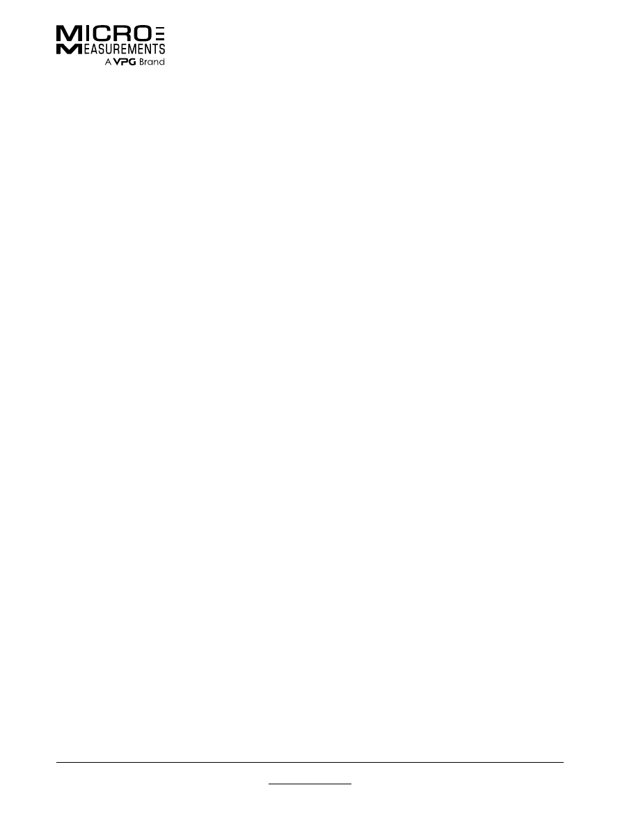
CUSTOM GAGES
Micro-Measurements maintains the most extensive variety of catalog
strain gages available today. Whether for stress analysis, transducer
manufacturing, or special-purpose applications, we have not only a wide
selection, but also a large and varied inventory that is readily available for
immediate delivery.
However, many of our customers have applications requiring gages that
are manufactured to their individual specifications. While we believe our
wide variety of standard catalog gages will satisfy most requirements, we
recognize the need for custom products and are committed to serving it well.
To request a quotation for a custom gage, please contact our Applications
Engineering Department.
• Linear patterns
• Tee rosettes
• Rectangular rosettes
• Delta rosettes
• Shear/torque patterns
For each of these grid geometries, those patterns most commonly used by our customers are listed first with complete
specifications. Additional listings with partial specifications follow for the less commonly used patterns. In both listings,
the gage patterns appear in alpha-numeric order, increasing from the shortest grid lengths to the longest.
Some seldom, if ever, ordered patterns listed in previous versions of this databook have been omitted. We will, of course,
continue to make these patterns available upon request for customers presently using them. For details, contact the
Applications Engineering Department at the Micro-Measurements sales office nearest you.
Separate listings are provided for special-use strain gages and sensors:
• Residual stress
• Magnetic fields
• Weldable gages
• High temperature gages
• Manganin pressure gages
• Shear modulus gages
• Embedment gages
• Temperature sensors
• Crack detection sensors
• Crack propagation sensors
• Displacement sensors
For technical questions, contact
mm@vpgsensors.com
Document No.: 11501
Revision: 26-Aug-2015
www.micro-measurements.com
7
General Information
Stress Analysis Strain Gages
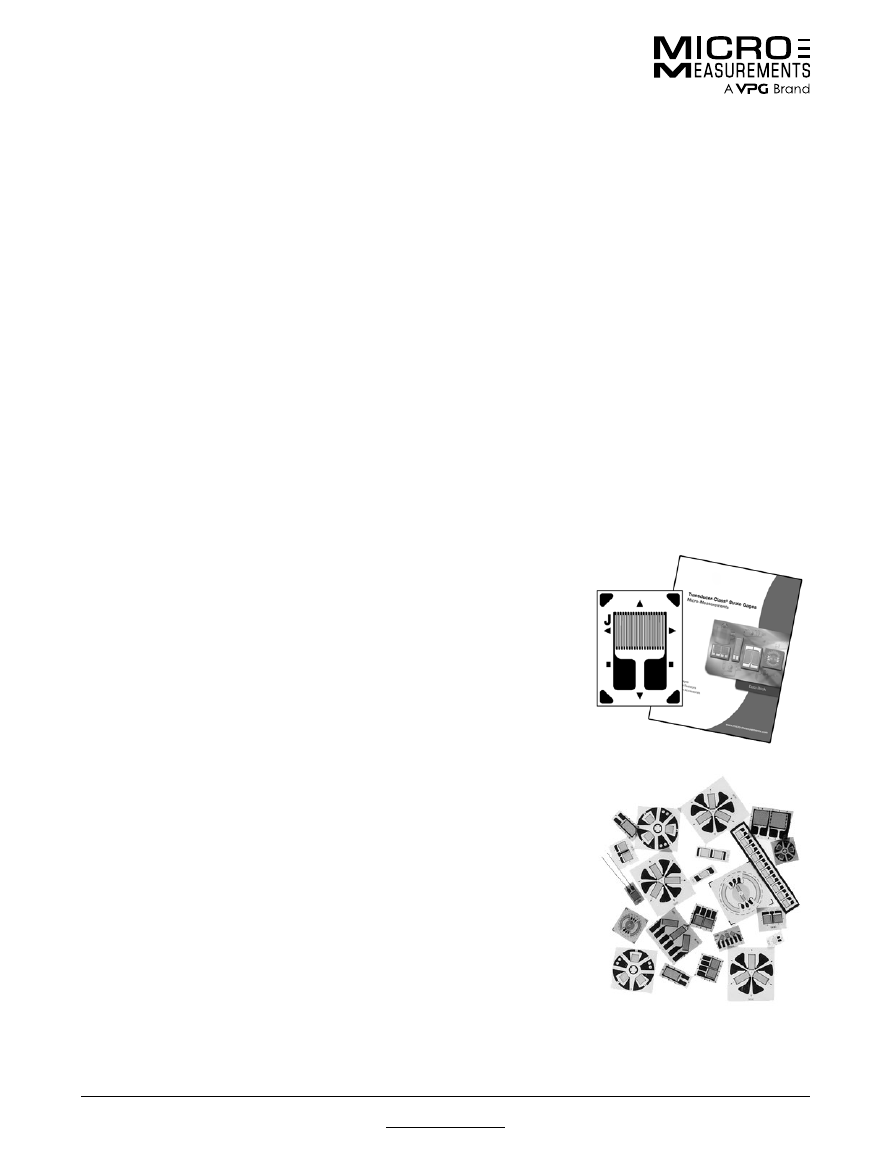
APPLICATIONS SUPPORT
Micro-Measurements maintains an experienced and highly trained
applications engineering staff. Our Applications Engineers are as close as
your telephone, and we urge you to call them for recommendations in strain
gage selection to satisfy your particular test requirements.
TECHNICAL INFORMATION
Detailed technical information about the selection and application of
strain gages can be found in the special series of Tech Notes, Tech Tips,
and Instruction Bulletins on strain gage technology. Thorough familiarity
with these publications will help ensure consistent success in the use of
Micro-Measurements strain gages.
We also offer our customers an extensive assortment of additional product
and technical literature, available in the strain gage technology knowledge
base on our website at:
http://www.vishaypg.com/micro-measurements/stress-analysis-strain-
gages/knowledge-base-list/.
STRAIN GAGE ACCESSORIES AND INSTRUMENTATION
In addition to an extensive selection of strain gages, Micro-Measurements
offers a complete range of complementary products. Strain gage
accessories include surface preparation materials, adhesives, installation
tools, protective coatings, leadwire, and a host of other application tools,
hardware, and supplies. Instruments range from portable, digital strain
indicators, to sophisticated computer-controlled systems for the acquisition,
storage, and reduction of test data. Both static and dynamic measuring
instruments are available—each uniquely designed to provide stable,
accurate, and reliable strain measurement.
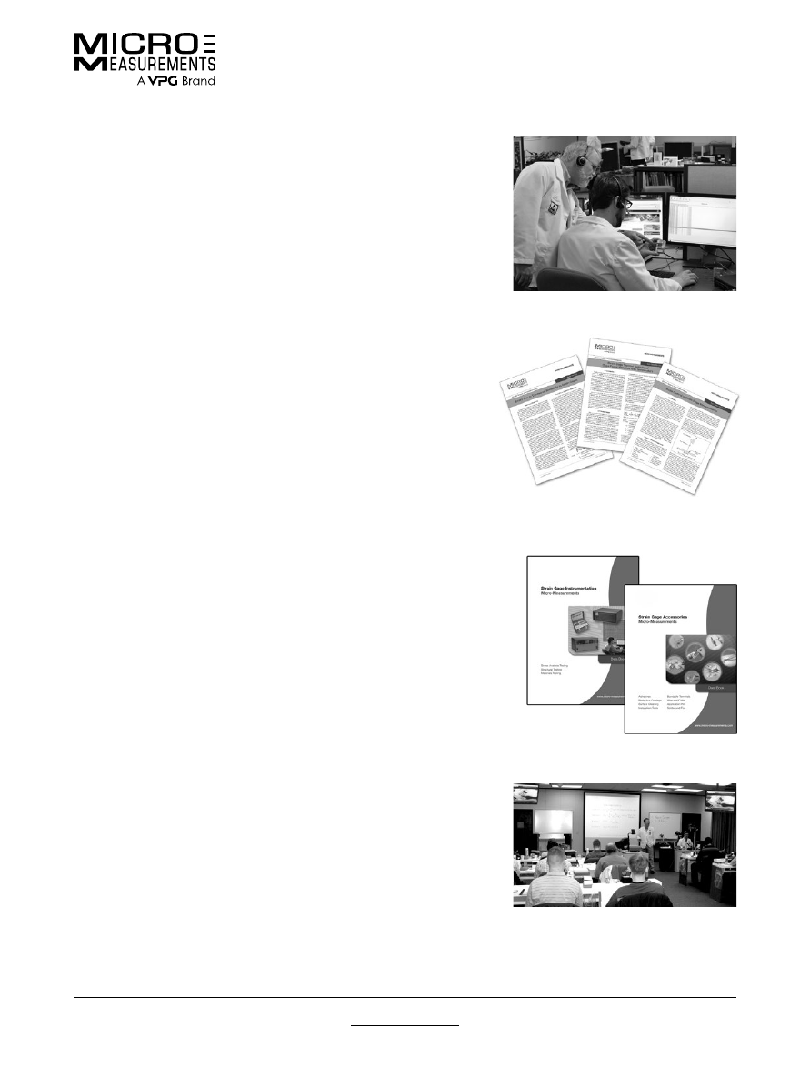
TRAINING PROGRAMS
Training customers in the proper use of strain measurement techniques is
an essential part of the Micro-Measurements philosophy. In support of this
principle, Micro-Measurements conducts an extensive series of regularly
scheduled technical seminars, workshops, and short courses. Course
instructors are recognized authorities in their field. Training sessions are
conducted at our facilities in the United States and Europe, as well as at
hotels and educational institutions around the world. For schedules, go to:
http://www.vishaypg.com/micro-measurements/training-programs/
For technical questions, contact
mm@vpgsensors.com
www.micro-measurements.com
8
Document No.: 11502
Revision: 26-Aug-2015
Designation System
Stress Analysis Strain Gages
Stress Analysis Strain Gages
Self-Temperature-Compensation (S-T-C)
Foil Alloy
Carrier Matrix (Backing)
Example:
Option XX
X X X - X X - X X X X X - X X X
The Strain Gage Designation System described below applies to Micro-Measurements General-Use Strain Gages.
Resistance in Ohms
Optional Feature
Active Gage Length in Mils
[0.001 in
(0.0254 mm)
]
Grid and Tab Geometry
A
:
Constantan alloy in
self-temperature-
compensated form.
P
: Annealed
Constantan.
D
:
Isoelastic alloy.
K
:
Nickel-chromium
alloy (similar to
Karma).
The S-T-C number
is the approximate
thermal expansion
coefficient in ppm/°F of
the structural material
on which the gage is to
be used. The following
S-T-C numbers are
available:
A
:
00, 03, 05, 06, 09,
13, 15, 18, 30, 50
P
: 08, 40
K
:
00, 03, 05, 06, 09,
13, 15
D
:
Not available in
self-temperature-
compensated form.
‘DY’ is used instead.
E
: Open-faced cast polyimide
backing.
CE
: Thin, flexible gages with
a cast polyimide backing
and encapsulation featuring
large, rugged, copper-
coated solder tabs. This
construction provides
optimum capability for
direct leadwire attachment.
L2
: Thin, laminated, polyimide-
film backing featuring
encapsulated grids with
preattached leadwire
ribbons.
C2
: Thin, laminated, polyimide-
film backing featuring
encapsulated grids with
leadwire cables.
W
: Fully encapsulated,
glass-fiber-reinforced
epoxy phenolic resin. High
endurance leadwires.
N2
: The ‘N2’ matrix provides an
open faced gage on a thin,
high-performance laminated
polyimide film backing.
S2
: Gage grid and solder tabs
fully encapsulated in a thin,
flexible, laminated polyimide
film. Provided with large
[0.030 in
(0.75 mm)
] solder
pads for ease of leadwire
attachment.
S
: Full encapsulation identical
to the W matrix, but with
solder dot connections
instead of leadwires.
W
: Integral printed
circuit terminal,
polyimide
encapsulation.
E
: Polyimide
encapsulation,
leaving a portion
of solder tab
exposed.
SE
: Solder dots
plus polyimide
encapsulation.
L
: Preattached, soft,
formable copper
leads.
LE
: Leads plus
polyimide
encapsulation.
P
: Preattached
leadwire cables
and encapsulation.
P2
: Preattached
leadwire cables for
CEA-Series gages.
For technical questions, contact
mm@vpgsensors.com
Document No.: 11503
Revision: 26-Aug-2015
www.micro-measurements.com
9
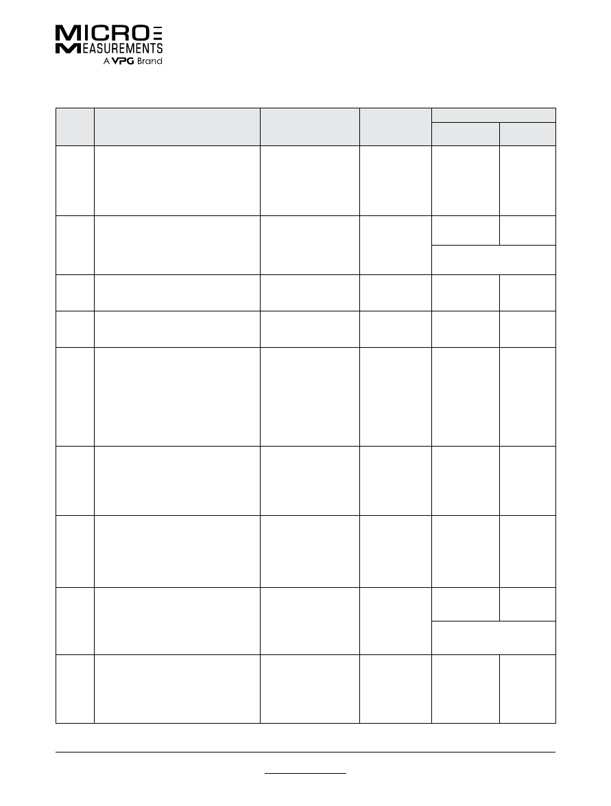
Gage Series Selection Chart
Standard Stress Analysis Strain Gages
Standard Stress Analysis Strain Gages
GAGE
SERIES
DESCRIPTION AND
PRIMARY APPLIATION
TEMPERATURE
RANGE
STRAIN
RANGE
FATIGUE LIFE
STRAIN LEVEL
IN µ
ε
NUMBER
0F CYCLES
EA
Constantan foil in combination with a tough,
flexible, polyimide backing. Wide range of
options available. Primarily intended for
general-purpose static and dynamic stress
analysis. Not recommended for highest
accuracy transducers.
Normal:
–100° to +350°F
(–75° to +175°C)
Special or short term:
–320° to +400°F
(–195° to +205°C)
±3% for gage
lengths under
1/8 in (3.2 mm)
±5% for 1/8 in
and over
±1800
±1500
±1200
10
5
10
6
10
8
CEA
Universal general-purpose strain gages.
Constantan grid completely encapsulated
in polyimide, with large, rugged copper-
coated tabs. Primarily used for general-
purpose static and dynamic stress analysis.
Normal:
–100° to +350°F
(–75° to +175°C)
Stacked rosettes limited
to +150°F (+65°C)
±3% for gage
lengths under
1/8 in (3.2 mm)
±5% for 1/8 in
and over
±1500
±1500
10
5
10
6
*
*Fatigue life improved
using low-modulus solder.
C2A
General-purpose stress analysis strain
gages. Supplied with preattached cables
for direct connection to instrumentation.
–60° to +180°F
(–50° to +80°C)
±3%
±1700
±1500
10
5
10
6
L2A
General-purpose stress analysis strain
gages. Supplied with preattached leadwire
ribbons.
–100° to +250°F
(–75° to +120°C)
±3%
±1700
±1500
10
5
10
6
N2A
Open-faced constantan foil gages with a
thin, laminated, polyimide-film backing.
Primarily recommended for use in
precision transducers, the N2A Series is
characterized by low and repeatable creep
performance. Also recommended for stress
analysis applications employing large gage
patterns, where the especially flat matrix
eases gage installation.
Normal static
transducer service:
–100° to +200°F
(–75° to +95°C)
±3%
±1700
±1500
10
6
10
7
WA
Fully encapsulated constantan gages with
high-endurance leadwires. Useful over
wider temperature ranges and in more
extreme environments than EA Series.
Option W available on some patterns, but
restricts fatigue life to some extent.
Normal:
–100° to +400°F
(–75° to +205°C)
Special or short term:
–320° to +500°F
(–195° to +260°C)
±2%
±2000
±1800
±1500
10
5
10
6
10
7
SA
Fully encapsulated constantan gages with
solder dots. Same matrix as WA Series.
Same uses as WA Series but derated
somewhat in maximum temperature and
operating environment because of solder
dots.
Normal:
–100° to +400°F
(–75° to +205°C)
Special or short-term:
–320° to +450°F
(–195° to +230°C)
±2%
±1800
±1500
10
6
10
7
EP
Specially annealed constantan foil with
tough, high-elongation polyimide backing.
Used primarily for measurements of large
post-yield strains. Available with Options
E, L, and LE (may restrict elongation
capability).
–100° to +400°F
(–75° to +205°C)
±10% for gage
lengths under
1/8 in (3.2 mm)
±20% for 1/8 in
and over
±1000
10
4
EP gages show zero shift
under high-cyclic strains.
ED
Isoelastic foil in combination with tough,
flexible polyimide film. High gage factor and
extended fatigue life excellent for dynamic
measurements. Not normally used in static
measurements due to very high thermal-
output characteristics.
Dynamic:
–320° to +400°F
(–195° to +205°C)
±2%
Nonlinear at
strain levels
over ±0.5%
±2500
±2200
10
6
10
7
For technical questions, contact
mm@vpgsensors.com
www.micro-measurements.com
10
Document No.: 11503
Revision: 26-Aug-2015
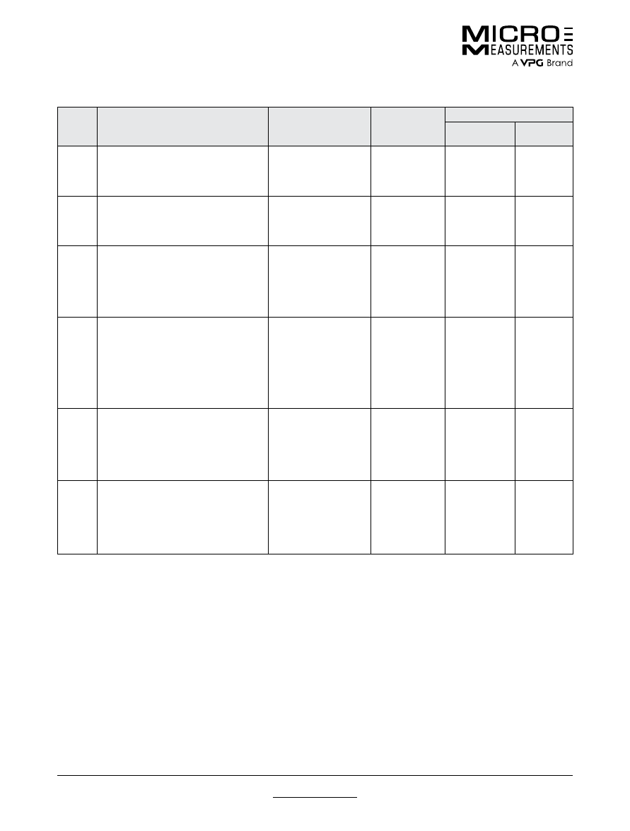
Gage Series Selection Chart
Standard Stress Analysis Strain Gages
GAGE
SERIES
DESCRIPTION AND
PRIMARY APPLIATION
TEMPERATURE
RANGE
STRAIN
RANGE
FATIGUE LIFE
STRAIN LEVEL
IN µ
ε
NUMBER
0F CYCLES
WD
Fully encapsulated isoelastic gages
with high-endurance leadwires. Used in
wide-range dynamic strain measurement
applications in severe environments.
Dynamic:
–320° to +500°F
(–195° to +260°C)
±1.5%
Nonlinear at
strain levels
over ±0.5%
±3000
±2500
±2200
10
5
10
7
10
8
SD
Equivalent to WD Series, but with solder
dots instead of leadwires.
Dynamic:
–320° to +400°F
(–195° to +205°C)
±1.5%
Nonlinear at
strain levels
over ±0.5%
±2500
±2200
10
6
10
7
EK
K-alloy foil in combination with a tough,
flexible polyimide backing. Primarily
used where a combination of higher
grid resistances, stability at elevated
temperature, and greatest backing flexibility
are required. Supplied with Option DP.
Normal:
–320° to +350°F
(–195° to +175°C)
Special or short term:
–452° to +400°F
(–269° to +205°C)
±1.5%
±1800
10
7
WK
Fully encapsulated K-alloy gages with high
endurance leadwires. Widest temperature
range and most extreme environmental
capability of any general-purpose gage
when self-temperature compensation is
required. Option W available on some
patterns, but restricts both fatigue life and
maximum operating temperature.
Normal:
–452° to +550°F
(–269° to +290°C)
Special or short term:
–452° to +750°F
(–269° to +400°C)
±1.5%
±2200
±2000
10
6
10
7
SK
Fully encapsulated K-alloy gages with
solder dots. Same uses as WK Series,
but derated in maximum temperature and
operating environment because of solder
dots.
Normal:
–452° to +450°F
(–269° to +230°C)
Special or short term:
–452° to +500°F
(–269° to +260°C)
±1.5%
±2200
±2000
10
6
10
7
S2K
K-alloy foil laminated to 0.001 in (0.025 mm)
thick, high-performance polyimide backing,
with a laminated polyimide overlay fully
encapsulating the grid and solder tabs.
Provided with large solder dots for ease of
leadwire attachment.
Normal:
–100° to +250°F
(–75° to +120°C)
Special or short term:
–300° to +300°F
(–185° to +150°C)
±1.5%
±1800
±1500
10
6
10
7
Notes:
The performance data given here are nominal, and apply primarily to gages of 0.125-in (3-mm) gage length or larger.
Refer to Gage Series/Optional Feature data sheet for more detailed description and performance specifications.
For technical questions, contact
mm@vpgsensors.com
Document No.: 11504
Revision: 26-Aug-2015
www.micro-measurements.com
11
Selection Criteria
Stress Analysis Strain Gages
Stress Analysis Strain Gages
GAGE SELECTION
Many factors, such as test duration, strain range required,
and operating temperature, must be considered in
selecting the best strain gage/adhesive combination for a
given test profile. These factors and others are addressed
in Tech Note TN-505, “Strain Gage Selection—Criteria,
Procedures, Recommendations.”
SELF-TEMPERATURE
COMPENSATION (S-T-C)
All gages with XX as the second code group in the gage
designation are self-temperature-compensated for use
on structural materials with specific thermal expansion
coefficients. The table below lists S-T-C numbers and
test specimen materials to which gages are thermally
matched.
When ordering, replace the XX code group with the
desired S-T-C number, which is the approximate thermal
expansion coefficient of the structural material in ppm/°F.
The Gage Designation System lists the available S-T-C
numbers for specific grid alloys. The 06 and 13 values,
available in A and K alloys, are most common and more
likely to be in stock. When not otherwise specified, the 06
compensation is shipped.
GAGE RESISTANCE
Micro-Measurements strain gages are available in various
resistance values that range from 30 to 5000 ohms.
Strain gages with resistances of 120 and 350 ohms are
commonly used in experimental stress analysis testing.
For the majority of applications, 120-ohm gages are
usually suitable; 350-ohm gages would be preferred to
reduce heat generation (for the same applied voltage
across the gage), to decrease leadwire effects, or
to improve signal-to-noise ratios in the gage circuit.
Higher resistance gages are typically used in transducer
applications and on composite materials.
GAGE FACTOR
Gage Factor (GF) is the measure of sensitivity, or
output
,
produced by a resistance strain gage. Gage factor is
determined through calibration of the specific gage type,
and is the ratio between ΔR/R
o
and ΔL/L (strain), where
R
o
is the initial unstrained resistance of the gage. It is
affected somewhat by pattern size, geometry, S-T-C
number, and temperature. Each gage package is supplied
with the GF as well as its tolerance and temperature
sensitivity. Nominal gage factors for various alloys are:
A = 2.05; K = 2.1; D = 3.2; P = 2.00.
TRANSVERSE SENSITIVITY
All gages are sensitive, to some degree, to strains
transverse to the grid direction. The transverse sensitivity
factor (K
t
) is given with the engineering data supplied with
all gage types for which the data is relevant.
STRAIN GAGE ADHESIVE SELECTION
When selecting a strain gage, it is most important to
consider the adhesive that will be used to bond the
gage, since the adhesive becomes part of the gage
system and correspondingly affects the performance
of the gage. However, when the interaction of test
characteristics becomes too complex for selecting the
gage/adhesive combination in a straight forward manner,
contact our Applications Engineering Department for
recommendations.
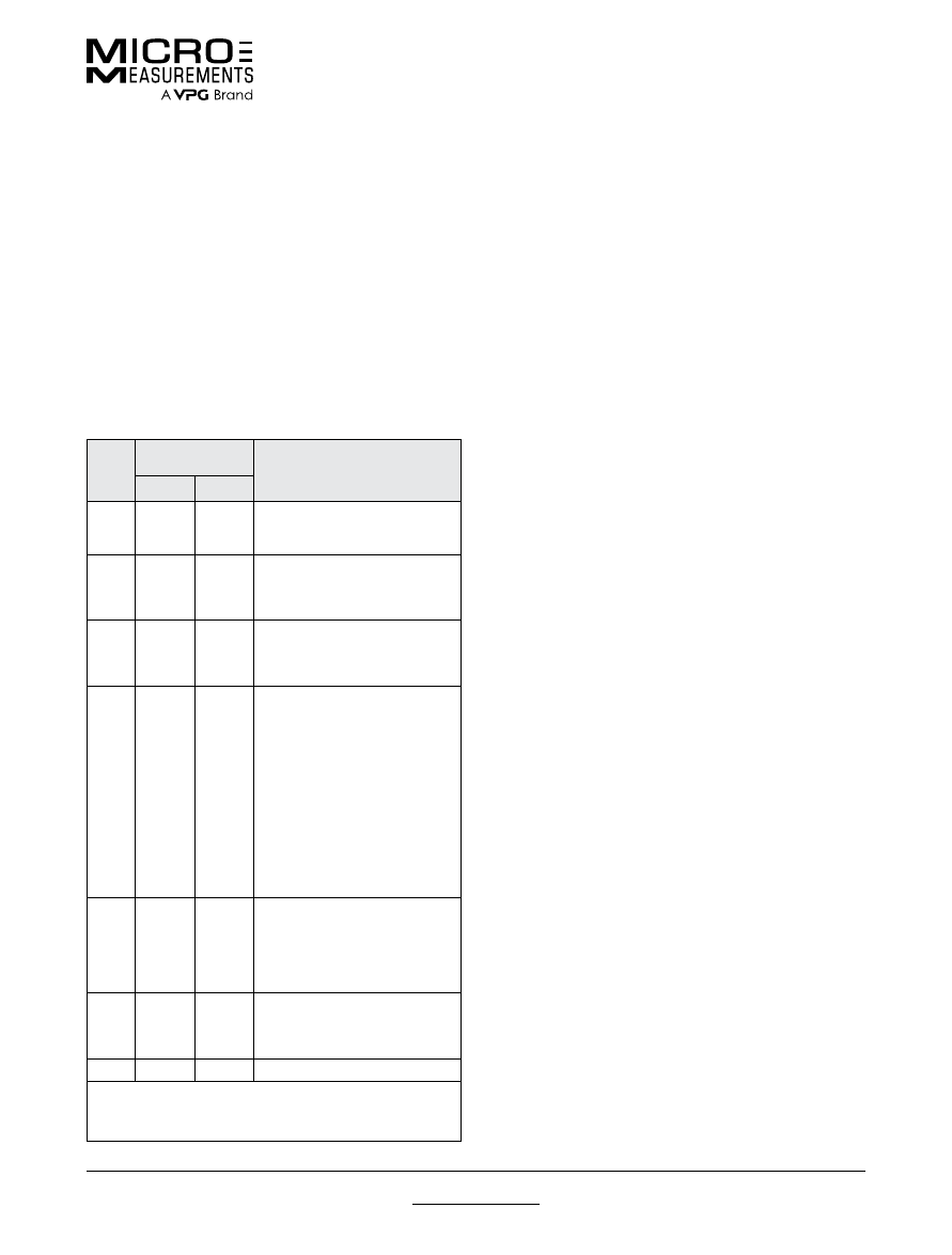
S-T-C
NO.
EXPANSION
COEFFICIENTS**
COMMON MATERIAL
per °F
per °C
00
0.8
0.3
0.017
1.4
0.5
0.03
Invar, Fe-Ni alloy
Quartz, fused
Titanium Silicate*, polycrystalline
03
3.0
2.7
2.4
3.1
5.4
4.9
4.3
5.6
Alumina, fired
Molybdenum*, pure
Tungsten, pure
Zirconium, pure
05
5.1
5.5
4.8
4.9
9.2
9.9
8.6
8.8
Glass, Soda-Lime-Silica
Stainless Steel, Ferritic (410)
Titanium, pure
Titanium Alloy, 6Al-4V*
06
6.4
6.0
7.0
6.7
7.5
6.6
6.3
6.7
6.0
5.7
5.0
11.5
10.8
12.6
12.1
13.5
11.9
11.3
12.1
10.8
10.3
9.0
Beryllium, pure
Cast Iron, grey
Inconel, Ni-Cr-Fe alloy
Inconel X, Ni-Cr-Fe alloy
Monel, Ni-Cu alloy
Nickel-A, Cu-Zn-Ni alloy
Steel alloy, 4340
Steel, Carbon, 1008, 1018*
Steel, Stainless,
Age Hardenable (17-4PH)
Steel, Stainless,
Age Hardenable (17-7PH)
Steel, Stainless,
Age Hardenable (PH15-7Mo)
09
9.3
10.2
9.2
9.6
8.0
8.9
16.7
18.4
16.5
17.3
14.4
16.0
Beryllium Copper, Cu 75, BE 25
Bronze, Phosphor, Cu 90, Sn 10
Copper, pure
Steel, Stainless, Austenitic (304*)
Steel, Stainless, Austenitic (310)
Steel, Stainless, Austenitic (316)
13
12.9
11.1
13.0
23.2
20.0
23.4
Aluminum Alloy,
2024-T4*, 7075 T6
Brass, Cartridge, Cu 70-Zn 30
Tin, pure
15
14.5
26.1
Magnesium Alloy*, AZ-318
* Indicates type of material used in determining thermal output curves
supplied with Micro-Measurements strain gages.
** Nominal values at or near room temperature for temperature
coefficient of expansion values.

For technical questions, contact
mm@vpgsensors.com
www.micro-measurements.com
12
Document No.: 11504
Revision: 26-Aug-2015
Selection Criteria
Stress Analysis Strain Gages
CUSTOM GAGES
Unusual applications occasionally require a strain gage
which is neither listed in the catalog nor available by
adding special optional features. Often a custom product
can be designed to fit such needs.
Careful consideration is given to the backing, foil, S-T-C,
gage length, pattern, resistance and resistance tolerance,
operating temperature range, test duration, maximum
strain, cyclic endurance, leads, encapsulation, and trim
so that the custom gage is designed to properly meet the
user’s needs. Examples of custom gages include such
features as unusual patterns, special trim dimensions, and
nonstandard lead materials or length.
A special part number is normally assigned to each
custom gage. Doing so ensures that the correct gage is
produced each time it is ordered. A set-up charge and a
minimum order will normally apply. For further information
contact our Applications Engineering Department.
For technical questions, contact
mm@vpgsensors.com
Document No.: 11505
Revision: 05-Jan-2016
www.micro-measurements.com
13
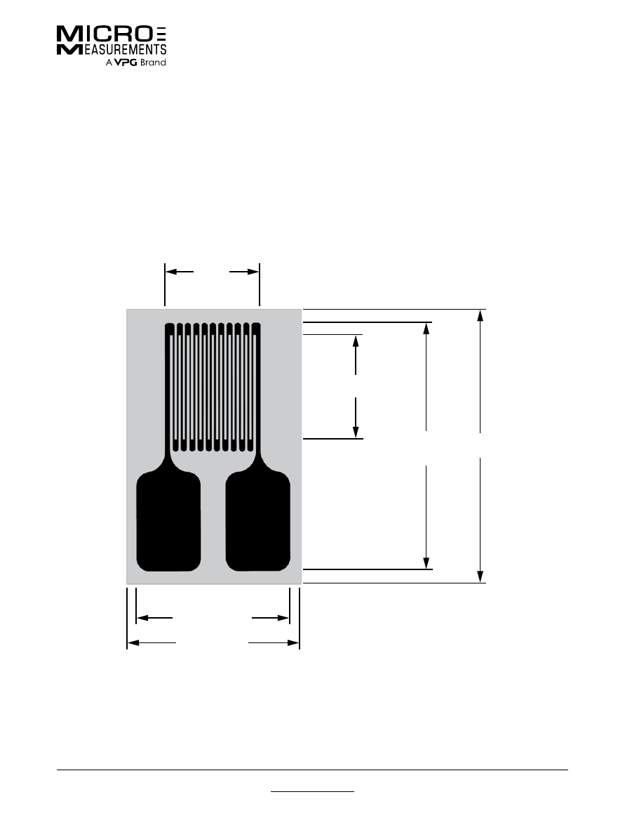
Strain Gage Dimensions
Strain Gage Dimensions
Strain Gage Dimensions
Gage length is an important consideration in strain gage selection, and is usually the first parameter to be defined.
Dimensions listed for gage length (as measured inside the grid endloops) and grid width refer to active grid dimensions.
Overall length and width refer to the actual foil pattern, not including alignment marks or backing.
The matrix size represents the approximate dimensions of the backing/matrix of the gage as shipped. Matrix dimensions
are nominal, with a usual tolerance of ±0.015 in (±0.4 mm). If the gages are encapsulated, the matrix may be smaller by
as much as 0.01 in (0.25 mm). Most patterns also include trim marks, and, for use in a restricted area, the backing/matrix
may be field-trimmed on all sides to within 0.01 in (0.25 mm) of the foil pattern without affecting gage performance.
GRID
WIDTH
MATRIX
LENGTH
OVERALL
PATTERN
LENGTH
GAGE
LENGTH
OVERALL
PATTERN WIDTH
MATRIX WIDTH

For technical questions, contact
mm@vpgsensors.com
www.micro-measurements.com
14

For technical questions, contact
mm@vpgsensors.com
www.micro-measurements.com
15
Linear Patterns
(General-Use)
FEATURES
• Gage patterns designed for measuring strain in a
single direction
• Single-grid and parallel dual-grid patterns
• Gage lengths from 0.008” (0.20 mm) to 4.000” (101.6 mm)
PATTERNS
015DJ .................................................. 16
015LW ................................................... 17
015UW ................................................. 18
031CE .................................................. 19
031CF ................................................... 20
031DE .................................................. 21
031EC .................................................. 22
032UW ................................................. 23
060PB ................................................... 24
062AK ................................................... 25
062AP ................................................... 26
062AQ ................................................. 27
062DN ................................................. 28
062ED .................................................. 29
062EN .................................................. 30
062LW .................................................. 31
062UW ................................................. 32
125AC .................................................. 33
125AD .................................................. 34
125BB ................................................... 35
125BT ................................................... 36
125BZ ................................................... 37
125LW .................................................. 38
125PC .................................................. 39
125UN ................................................. 40
125UW ................................................. 41
187UW ................................................. 42
250AE ................................................... 43
250BF ................................................... 44
250BG ................................................. 45
250BK ................................................... 46
250LW .................................................. 47
250PD .................................................. 48
250UN ................................................. 49
250UW ................................................. 50
375UW ................................................. 51
500BH ................................................. 52
500UW ................................................. 53
10CBE .................................................. 54
20CBW ................................................. 55
20CLW ................................................. 56
Other Linear Patterns .......................... 57
For technical questions, contact
mm@vpgsensors.com
www.micro-measurements.com
16
Document No.: 11068
Revision: 26-Aug-2015
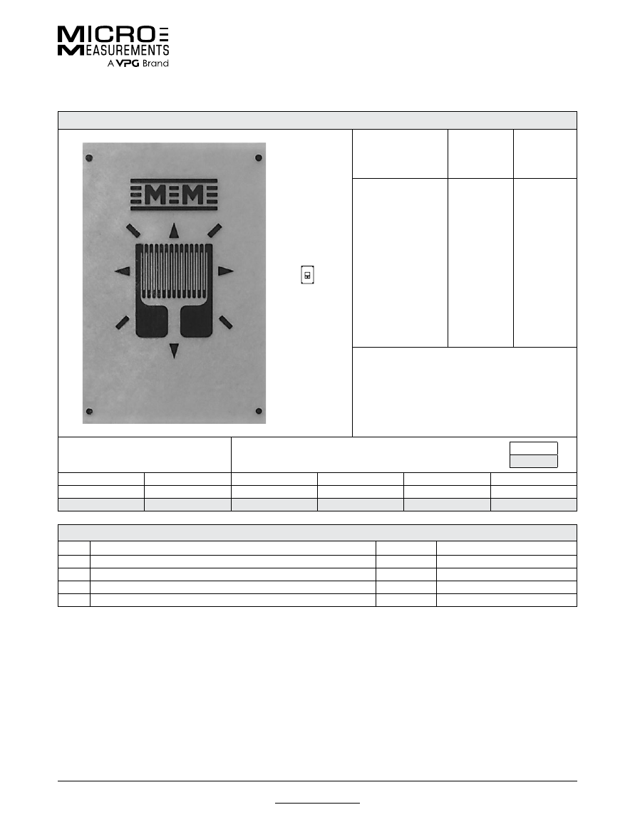
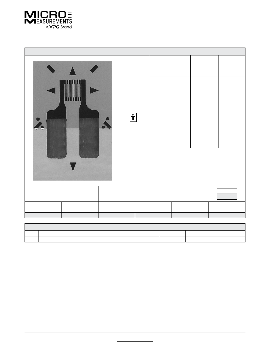
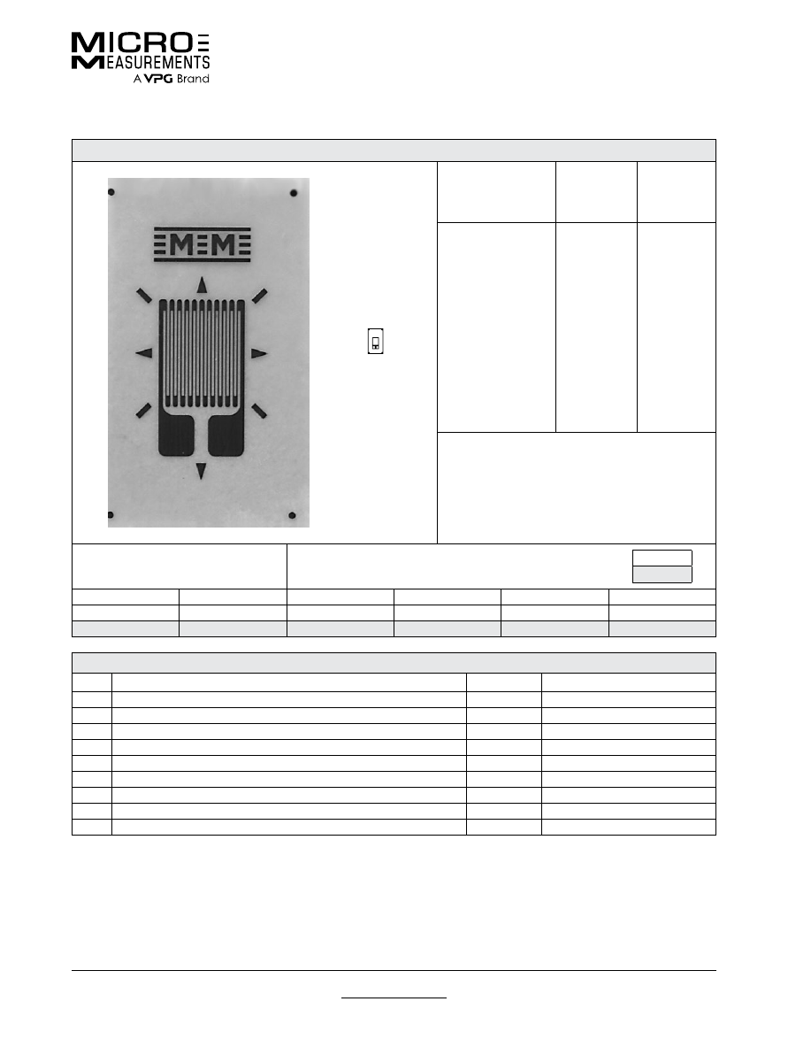
015DJ
General Purpose Strain Gages—Linear Pattern
General Purpose Strain Gages—Linear Pattern
GAGE PATTERN DATA
actual size
GAGE
DESIGNATION
See Note 1, 3
RESISTANCE
(OHMS)
See Note 2
OPTIONS
AVAILABLE
See Note 3
EA-XX-015DJ-120
EP-08-015DJ-120
SA-XX-015DJ-120
SK-XX-015DJ-120
120 ± 0.3%
120 ± 0.3%
120 ± 0.6%
120 ± 0.6%
L, LE
DESCRIPTION
Micro-miniature pattern with tab at each end of grid.
See also 015EH pattern.
GAGE DIMENSIONS
Legend
ES = Each Section
CP = Complete Pattern
S = Section (S1 = Section 1)
M = Matrix
inch
millimeter
Gage Length
Overall Length
Grid Width
Overall Width
Matrix Length
Matrix Width
0.015
0.100
0.020
0.020
0.23
0.12
0.38
2.54
0.51
0.51
5.8
3.0
GAGE SERIES DATA
—
See Gage Series datasheet for complete specifications
Series
Description
Strain Range
Temperature Range
EA
Constantan foil in combination with a tough, flexible, polyimide backing.
±3%
–100° to +350°F (–75° to +175°C)
EP
Annealed constantan foil with tough, high-elongation polyimide backing.
±10%
–100° to +400°F (–75° to +205°C)
SA
Fully encapsulated constantan gages with solder dots.
±2%
–100° to +400°F (–75° to +205°C)
SK
Fully encapsulated K-alloy gages with solder dots.
±1.5%
–452° to +450°F (–269° to +230°C)
Note 1:
Insert desired S-T-C number in spaces marked XX.
Note 2:
Tolerance is increased when Option W, E, SE, LE, or P is specified.
Note 3:
Products with designations and options shown in
bold
are not RoHS compliant.
For technical questions, contact
mm@vpgsensors.com
Document No.: 11376
Revision: 14-Oct-2015
www.micro-measurements.com
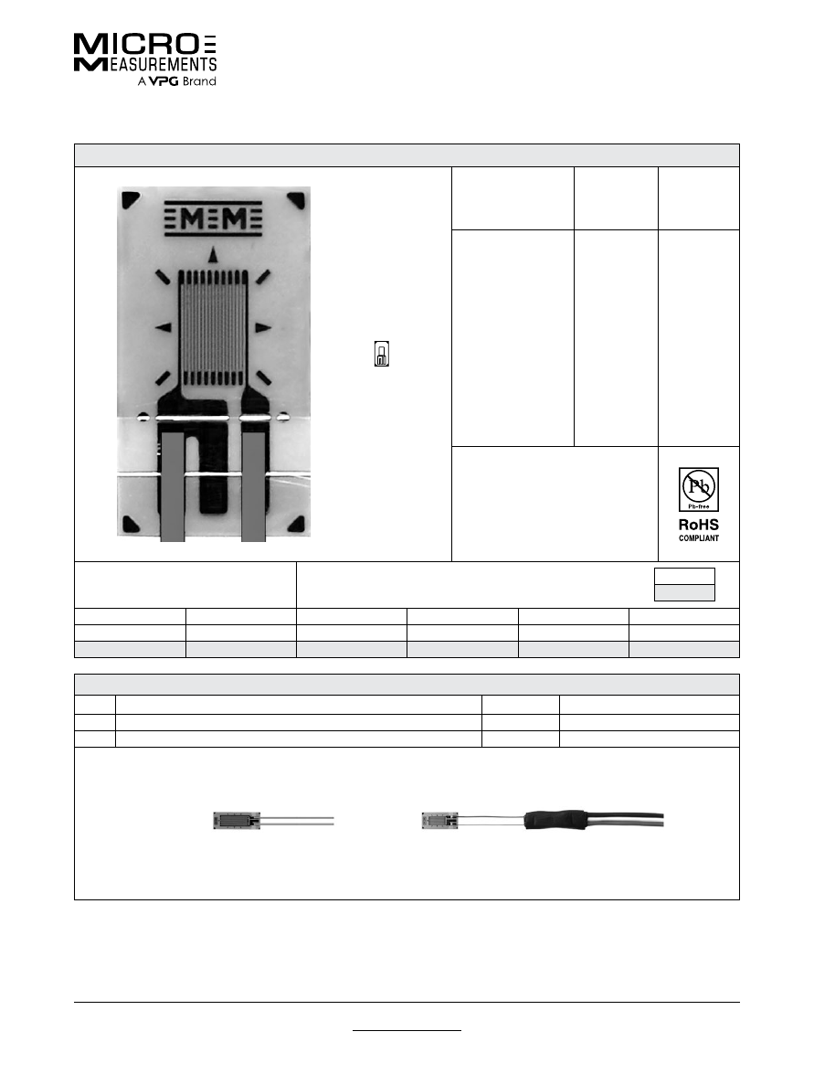
17
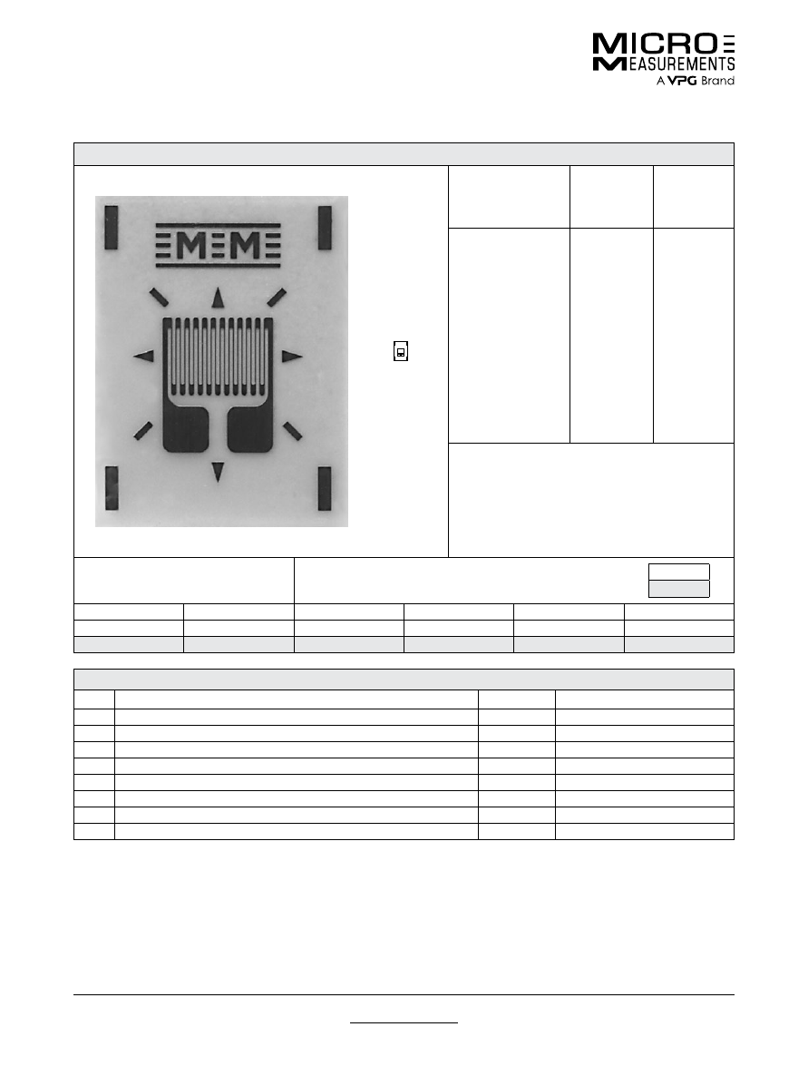
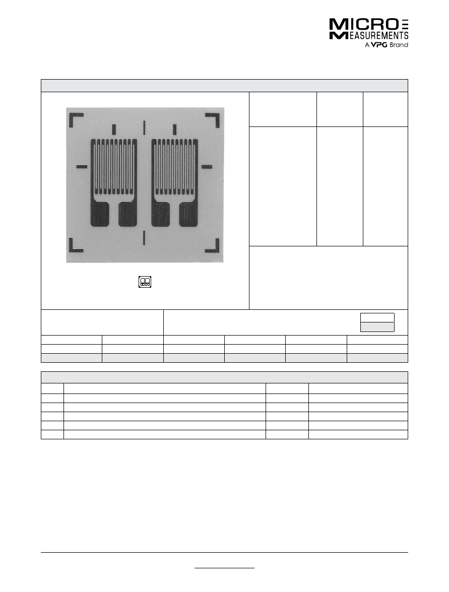
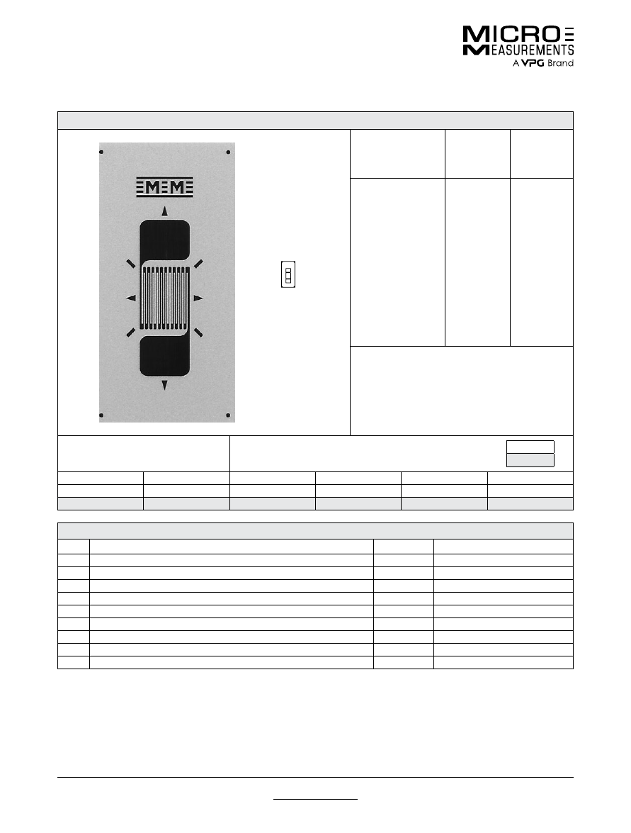
015LW
General Purpose Strain Gages—Linear Pattern
General Purpose Strain Gages—Linear Pattern
GAGE PATTERN DATA
actual size
GAGE
DESIGNATION
See Note 1
RESISTANCE
(OHMS)
OPTIONS
AVAILABLE
L2A-XX-015LW-120
C2A-XX-015LW-120
120 ± 0.6%
120 ± 0.6%
DESCRIPTION
Widely used general-purpose gage.
GAGE DIMENSIONS
Legend
ES = Each Section
CP = Complete Pattern
S = Section (S1 = Section 1)
M = Matrix
inch
millimeter
Gage Length
Overall Length
Grid Width
Overall Width
Matrix Length
Matrix Width
0.015
0.052
0.020
0.034
0.075
0.054
0.38
1.32
0.50
0.86
1.90
1.37
GAGE SERIES DATA
—
See Gage Series datasheet for complete specifications
Series
Description
Strain Range
Temperature Range
C2A
Encapsulated constantan gages with preattached ready-to-use cables.
±3%
–60° to +180°F (–50° to +80°C)
Example of an
L2A Construction
Example of an
C2A Construction
Note 1:
Insert desired S-T-C number in spaces marked XX.
For technical questions, contact
mm@vpgsensors.com
www.micro-measurements.com
18
Document No.: 11069
Revision: 28-Aug-2015
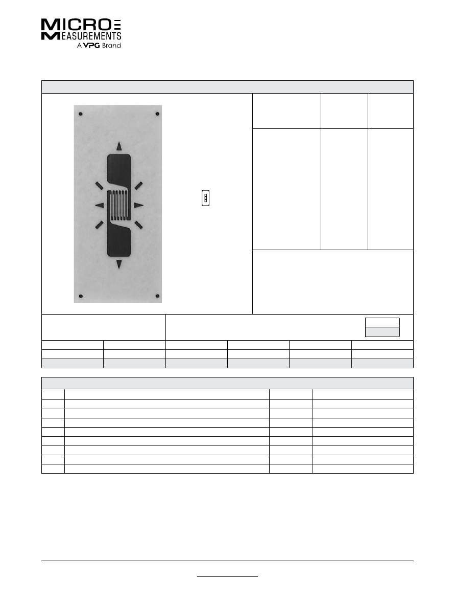
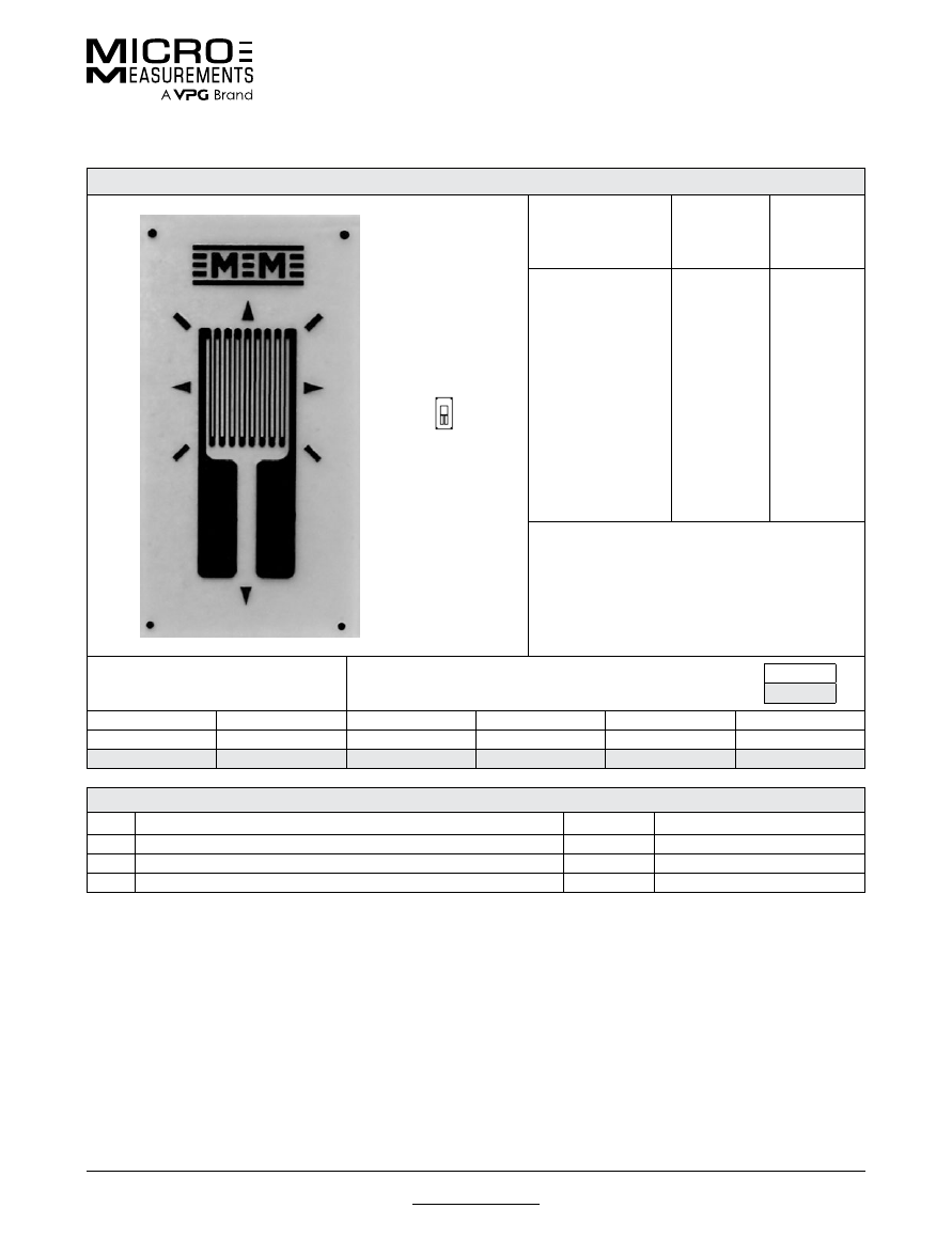
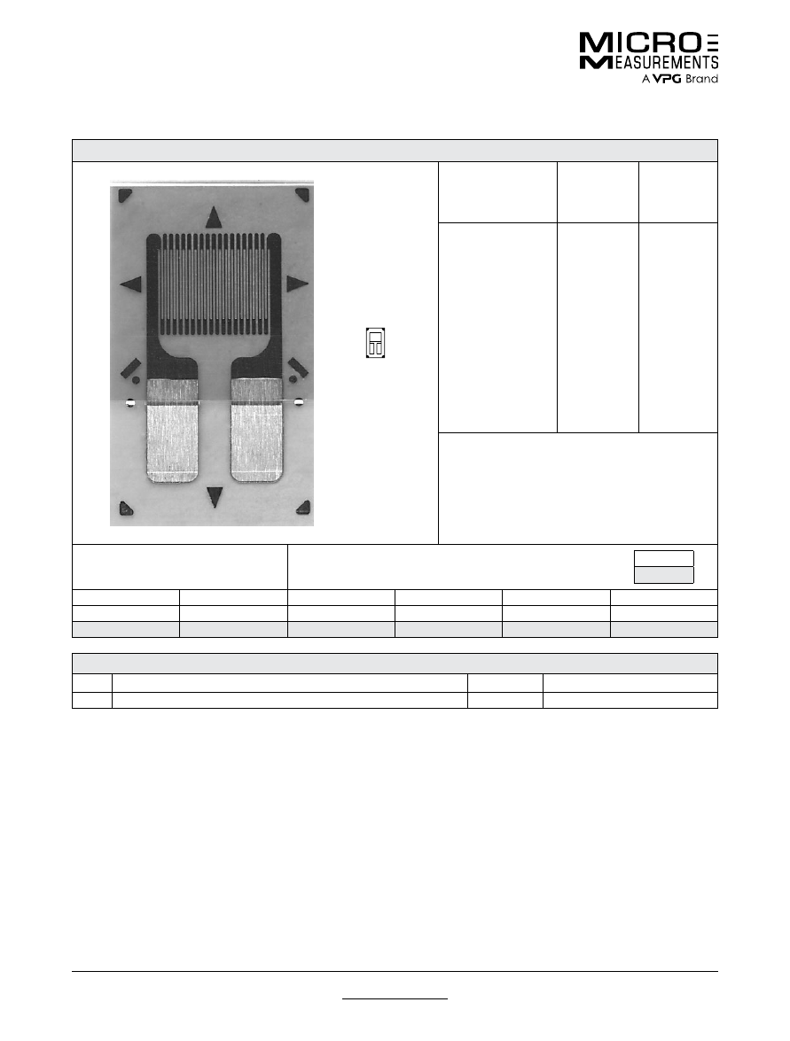
015UW
General Purpose Strain Gages—Linear Pattern
General Purpose Strain Gages—Linear Pattern
GAGE PATTERN DATA
actual size
GAGE
DESIGNATION
See Note 1
RESISTANCE
(OHMS)
OPTIONS
AVAILABLE
CEA-XX-015UW-120
120 ± 0.3%
DESCRIPTION
Micro-miniature pattern. Exposed
solder tab area is 0.06 x 0.04 (1.5 x
1.0 mm). See also 015CK pattern
GAGE DIMENSIONS
Legend
ES = Each Section
CP = Complete Pattern
S = Section (S1 = Section 1)
M = Matrix
inch
millimeter
Gage Length
Overall Length
Grid Width
Overall Width
Matrix Length
Matrix Width
0.015
0.140
0.020
0.105
0.24
0.18
0.38
3.56
0.51
2.67
6.1
4.6
GAGE SERIES DATA
—
See Gage Series datasheet for complete specifications
Series
Description
Strain Range
Temperature Range
CEA
Universal general-purpose strain gages.
±3%
–100° to +350°F (–75° to +175°C)
Note 1:
Insert desired S-T-C number in spaces marked XX.
For technical questions, contact
mm@vpgsensors.com
Document No.: 11070
Revision: 28-Aug-2015
www.micro-measurements.com
19
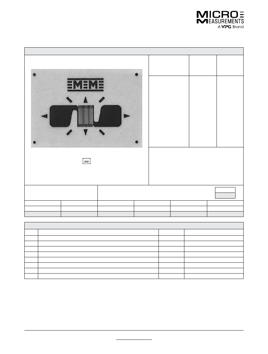
031CE
General Purpose Strain Gages—Linear Pattern
General Purpose Strain Gages—Linear Pattern
GAGE PATTERN DATA
actual size
GAGE
DESIGNATION
See Note 1, 3
RESISTANCE
(OHMS)
See Note 2
OPTIONS
AVAILABLE
See Note 3
EA-XX-031CE-350
WA-XX-031CE-350
EP-XX-031CE-350
SA-XX-031CE-350
350 ± 0.2%
350 ± 0.4%
350 ± 0.2%
350 ± 0.4%
W, E, L, LE,
P
DESCRIPTION
General-purpose high-resistance miniature gage.
GAGE DIMENSIONS
Legend
ES = Each Section
CP = Complete Pattern
S = Section (S1 = Section 1)
M = Matrix
inch
millimeter
Gage Length
Overall Length
Grid Width
Overall Width
Matrix Length
Matrix Width
0.031
0.076
0.062
0.062
0.23
0.16
0.79
1.93
1.57
1.57
5.8
4.1
GAGE SERIES DATA
—
See Gage Series datasheet for complete specifications
Series
Description
Strain Range
Temperature Range
EA
Constantan foil in combination with a tough, flexible, polyimide backing.
±3%
–100° to +350°F (–75° to +175°C)
WA
Fully encapsulated constantan gages with high-endurance leadwires.
±2%
–100° to +400°F (–75° to +205°C)
EP
Annealed constantan foil with tough, high-elongation polyimide backing.
±10%
–100° to +400°F (–75° to +205°C)
SA
Fully encapsulated constantan gages with solder dots.
±2%
–100° to +400°F (–75° to +205°C)
Note 1:
Insert desired S-T-C number in spaces marked XX.
Note 2:
Tolerance is increased when Option W, E, SE, LE, or P is specified.
Note 3:
Products with designations and options shown in
bold
are not RoHS compliant.
For technical questions, contact
mm@vpgsensors.com
www.micro-measurements.com
20
Document No.: 11071
Revision: 28-Aug-2015
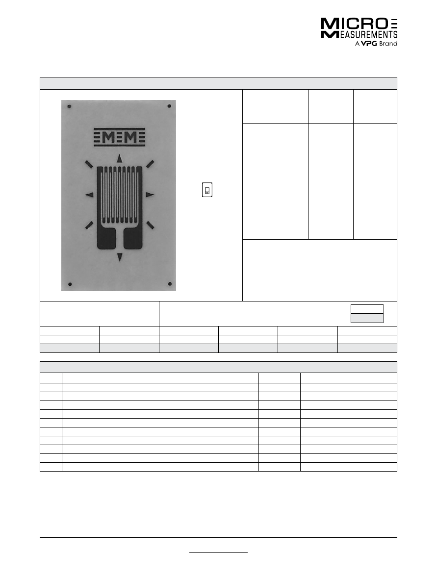
031CF
General Purpose Strain Gages—Linear Pattern
General Purpose Strain Gages—Linear Pattern
GAGE PATTERN DATA
actual size
GAGE
DESIGNATION
See Note 1, 3
RESISTANCE
(OHMS)
See Note 2
OPTIONS
AVAILABLE
See Note 3
EA-XX-031CF-120
ED-DY-031CF-350
WA-XX-031CF-120
WK-XX-031CF-350
EP-08-031CF-120
SA-XX-031CF-120
SK-XX-031CF-120
SK-XX-031CF-350
SD-DY-031CF-350
120 ± 0.2%
350 ± 0.4%
120 ± 0.4%
350 ± 0.4%
120 ± 0.2%
120 ± 0.4%
120 ± 0.4%
350 ± 0.4%
350 ± 0.8%
W, E, L, LE,
P
E, L*, LE*
DESCRIPTION
General-purpose miniature gage. Similar to 031CE
pattern except for resistance. See also 032UW pattern.
GAGE DIMENSIONS
Legend
ES = Each Section
CP = Complete Pattern
S = Section (S1 = Section 1)
M = Matrix
inch
millimeter
Gage Length
Overall Length
Grid Width
Overall Width
Matrix Length
Matrix Width
0.031
0.076
0.062
0.062
0.19
0.14
0.79
1.93
1.57
1.57
4.8
3.5
GAGE SERIES DATA
—
See Gage Series datasheet for complete specifications
Series
Description
Strain Range
Temperature Range
EA
Constantan foil in combination with a tough, flexible, polyimide backing.
±3%
–100° to +350°F (–75° to +175°C)
ED
Isoelastic foil in combination with tough, flexible polyimide film.
±2%
–320° to +400°F (–195° to +205°C)
WA
Fully encapsulated constantan gages with high-endurance leadwires.
±2%
–100° to +400°F (–75° to +205°C)
WK
Fully encapsulated K-alloy gages with high-endurance leadwires.
±1.5%
–452° to +550°F (–269° to +290°C)
EP
Annealed constantan foil with tough, high-elongation polyimide backing.
±10%
–100° to +400°F (–75° to +205°C)
SA
Fully encapsulated constantan gages with solder dots.
±2%
–100° to +400°F (–75° to +205°C)
SK
Fully encapsulated K-alloy gages with solder dots.
±1.5%
–452° to +450°F (–269° to +230°C)
SD
Equivalent to WD Series, but with solder dots instead of leadwires.
±1.5%
–320° to +400°F (–195° to +205°C)
Note 1:
Insert desired S-T-C number in spaces marked XX.
Note 2:
Tolerance is increased when Option W, E, SE, LE, or P is specified.
Note 3:
Products with designations and options shown in
bold
are not RoHS compliant.
*Options available but not normally recommended. See Optional Features data sheet for details.
For technical questions, contact
mm@vpgsensors.com
Document No.: 11072
Revision: 22-Sep-2015
www.micro-measurements.com
21
031DE
General Purpose Strain Gages—Linear Pattern
General Purpose Strain Gages—Linear Pattern
GAGE PATTERN DATA
actual size
GAGE
DESIGNATION
See Note 1, 3
RESISTANCE
(OHMS)
See Note 2
OPTIONS
AVAILABLE
See Note 3
EA-XX-031DE-120
EA-XX-031DE-350
ED-DY-031DE-350
WA-XX-031DE-120
WA-XX-031DE-350
WK-XX-031DE-350
EP-XX-031DE-120
SA-XX-031DE-350
SA-XX-031DE-350
SK-XX-031DE-120
SK-XX-031DE-350
SD-DY-031DE-350
120 ± 0.2%
350 ± 0.2%
350 ± 0.4%
120 ± 0.4%
350 ± 0.4%
350 ± 0.4%
120 ± 0.2%
350 ± 0.4%
350 ± 0.4%
120 ± 0.4%
350 ± 0.4%
350 ± 0.8%
E,
SE
, L, LE
E,
SE,
L, LE
E, L*, LE*
DESCRIPTION
General-purpose miniature gage.
GAGE DIMENSIONS
Legend
ES = Each Section
CP = Complete Pattern
S = Section (S1 = Section 1)
M = Matrix
inch
millimeter
Gage Length
Overall Length
Grid Width
Overall Width
Matrix Length
Matrix Width
0.031
0.140
0.032
0.032
0.27
0.12
0.79
3.56
0.81
0.81
6.9
3.0
GAGE SERIES DATA
—
See Gage Series datasheet for complete specifications
Series
Description
Strain Range
Temperature Range
EA
Constantan foil in combination with a tough, flexible, polyimide backing.
±3%
–100° to +350°F (–75° to +175°C)
ED
Isoelastic foil in combination with tough, flexible polyimide film.
±2%
–320° to +400°F (–195° to +205°C)
WA
Fully encapsulated constantan gages with high-endurance leadwires.
±2%
–100° to +400°F (–75° to +205°C)
WK
Fully encapsulated K-alloy gages with high-endurance leadwires.
±1.5%
–452° to +550°F (–269° to +290°C)
EP
Annealed constantan foil with tough, high-elongation polyimide backing.
±10%
–100° to +400°F (–75° to +205°C)
SA
Fully encapsulated constantan gages with solder dots.
±2%
–100° to +400°F (–75° to +205°C)
SK
Fully encapsulated K-alloy gages with solder dots.
±1.5%
–452° to +450°F (–269° to +230°C)
SD
Equivalent to WD Series, but with solder dots instead of leadwires.
±1.5%
–320° to +400°F (–195° to +205°C)
Note 1:
Insert desired S-T-C number in spaces marked XX.
Note 2:
Tolerance is increased when Option W, E, SE, LE, or P is specified.
Note 3:
Products with designations and options shown in
bold
are not RoHS compliant.
*Options available but not normally recommended. See Optional Features data sheet for details.
For technical questions, contact
mm@vpgsensors.com
www.micro-measurements.com
22
Document No.: 11073
Revision: 22-Sep-2015
031EC
General Purpose Strain Gages—Linear Pattern
General Purpose Strain Gages—Linear Pattern
GAGE PATTERN DATA
actual size
GAGE
DESIGNATION
See Note 1, 3
RESISTANCE
(OHMS)
See Note 2
OPTIONS
AVAILABLE
See Note 3
EA-XX-031EC-120
EA-XX-031EC-350
ED-DY-031EC-350
WA-XX-031EC-120
WA-XX-031EC-350
WK-XX-031EC-350
EP-08-031EC-120
SA-XX-031EC-120
SA-XX-031EC-350
SK-XX-031EC-120
SK-XX-031EC-350
SD-DY-031EC-350
120 ± 0.2%
350 ± 0.2%
350 ± 0.4%
120 ± 0.4%
350 ± 0.4%
350 ± 0.4%
120 ± 0.2%
120 ± 0.4%
350 ± 0.4%
120 ± 0.4%
350 ± 0.4%
350 ± 0.8%
E,
SE,
L, LE
E,
SE,
L, LE
E, L*, LE*
DESCRIPTION
General-purpose miniature gage. Similar to 031DE
pattern but with tab at each side of grid.
GAGE DIMENSIONS
Legend
ES = Each Section
CP = Complete Pattern
S = Section (S1 = Section 1)
M = Matrix
inch
millimeter
Gage Length
Overall Length
Grid Width
Overall Width
Matrix Length
Matrix Width
0.031
0.042
0.032
0.140
0.17
0.23
0.79
1.07
0.81
3.56
4.3
5.8
GAGE SERIES DATA
—
See Gage Series datasheet for complete specifications
Series
Description
Strain Range
Temperature Range
EA
Constantan foil in combination with a tough, flexible, polyimide backing.
±3%
–100° to +350°F (–75° to +175°C)
ED
Isoelastic foil in combination with tough, flexible polyimide film.
±2%
–320° to +400°F (–195° to +205°C)
WA
Fully encapsulated constantan gages with high-endurance leadwires.
±2%
–100° to +400°F (–75° to +205°C)
WK
Fully encapsulated K-alloy gages with high-endurance leadwires.
±1.5%
–452° to +550°F (–269° to +290°C)
EP
Annealed constantan foil with tough, high-elongation polyimide backing.
±10%
–100° to +400°F (–75° to +205°C)
SA
Fully encapsulated constantan gages with solder dots.
±2%
–100° to +400°F (–75° to +205°C)
SK
Fully encapsulated K-alloy gages with solder dots.
±1.5%
–452° to +450°F (–269° to +230°C)
SD
Equivalent to WD Series, but with solder dots instead of leadwires.
±1.5%
–320° to +400°F (–195° to +205°C)
Note 1:
Insert desired S-T-C number in spaces marked XX.
Note 2:
Tolerance is increased when Option W, E, SE, LE, or P is specified.
Note 3:
Products with designations and options shown in
bold
are not RoHS compliant.
*Options available but not normally recommended. See Optional Features data sheet for details.
For technical questions, contact
mm@vpgsensors.com
Document No.: 11075
Revision: 23-Oct-2015
www.micro-measurements.com
23
032UW
General Purpose Strain Gages—Linear Pattern
General Purpose Strain Gages—Linear Pattern
GAGE PATTERN DATA
actual size
GAGE
DESIGNATION
See Note 1
RESISTANCE
(OHMS)
OPTIONS
AVAILABLE
See Note 2
CEA-XX-032UW-120
CEA-XX-032UW-350
120 ± 0.3%
350 ± 0.3%
P2
P2
DESCRIPTION
General-purpose miniature gage. Exposed solder tab
area is 0.07 x 0.04 in [1.8 x 1.0 mm].
GAGE DIMENSIONS
Legend
ES = Each Section
CP = Complete Pattern
S = Section (S1 = Section 1)
M = Matrix
inch
millimeter
Gage Length
Overall Length
Grid Width
Overall Width
Matrix Length
Matrix Width
0.032
0.180
0.060
0.120
0.27
0.19
0.81
4.57
1.52
3.05
6.9
4.8
GAGE SERIES DATA
—
See Gage Series datasheet for complete specifications
Series
Description
Strain Range
Temperature Range
CEA
Universal general-purpose strain gages.
±3%
–100° to +350°F (–75° to +175°C)
Note 1:
Insert desired S-T-C number in spaces marked XX.
Note 2:
Products with designations and options shown in
bold
are not RoHS compliant.
For technical questions, contact
mm@vpgsensors.com
www.micro-measurements.com
24
Document No.: 11327
Revision: 22-Sep-2015
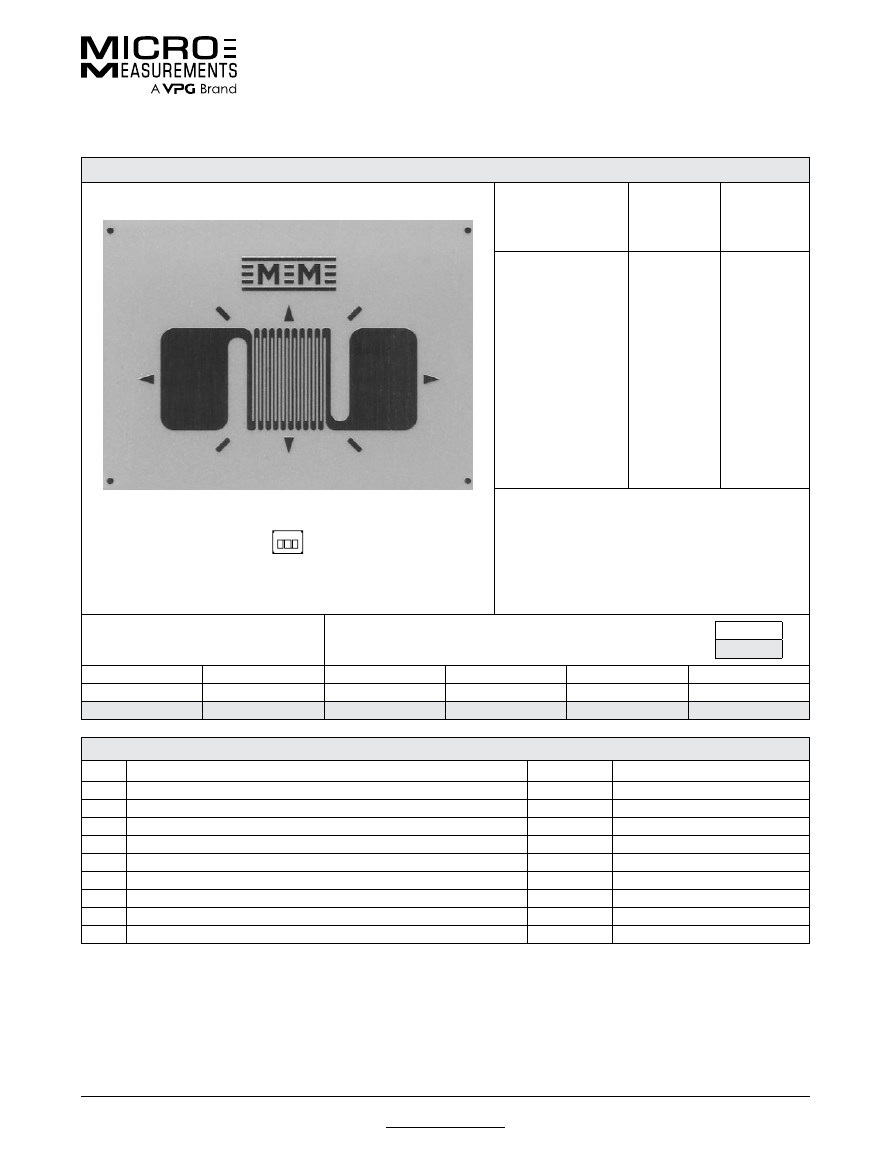
060PB
General Purpose Strain Gages—Linear Pattern
General Purpose Strain Gages—Linear Pattern
GAGE PATTERN DATA
actual size
GAGE
DESIGNATION
See Note 1, 3
RESISTANCE
(OHMS)
See Note 2
OPTIONS
AVAILABLE
See Note 3
EA-XX-060PB-120
EA-XX-060PB-350
WA-XX-060PB-120
WA-XX-060PB-350
WK-XX-060PB-350
WK-XX-060PB-500
SA-XX-060PB-120
SA-XX-060PB-350
SK-XX-060PB-350
SK-XX-060PB-500
120 ± 0.2%
350 ± 0.2%
120 ± 0.3%
350 ± 0.3%
350 ± 0.3%
500 ± 0.3%
120 ± 0.3%
350 ± 0.3%
350 ± 0.3%
500 ± 0.3%
W, E, L, LE
W, E, L, LE
W*
W*
W
*
W
*
DESCRIPTION
Dual pattern for back-to-back bending sections.
Longitudinal grid centerlines spaced 0.085 in (2.16
mm) apart.
GAGE DIMENSIONS
Legend
ES = Each Section
CP = Complete Pattern
S = Section (S1 = Section 1)
M = Matrix
inch
millimeter
Gage Length
Overall Length
Grid Width
Overall Width
Matrix Length
Matrix Width
0.060 ES
0.120 CP
0.065 ES
0.150 CP
0.18
0.20
1.52 ES
3.05 CP
1.65 ES
3.81 CP
4.6
5.1
GAGE SERIES DATA
—
See Gage Series datasheet for complete specifications
Series
Description
Strain Range
Temperature Range
EA
Constantan foil in combination with a tough, flexible, polyimide backing.
±3%
–100° to +350°F (–75° to +175°C)
WA
Fully encapsulated constantan gages with high-endurance leadwires.
±2%
–100° to +400°F (–75° to +205°C)
WK
Fully encapsulated K-alloy gages with high-endurance leadwires.
±1.5%
–452° to +550°F (–269° to +290°C)
SA
Fully encapsulated constantan gages with solder dots.
±2%
–100° to +400°F (–75° to +205°C)
SK
Fully encapsulated K-alloy gages with solder dots.
±1.5%
–452° to +450°F (–269° to +230°C)
Note 1:
Insert desired S-T-C number in spaces marked XX.
Note 2:
Tolerance is increased when Option W, E, SE, LE, or P is specified.
Note 3:
Products with designations and options shown in
bold
are not RoHS compliant.
*Options available but not normally recommended. See Optional Features data sheet for details.
For technical questions, contact
mm@vpgsensors.com
Document No.: 11078
Revision: 22-Sep-2015
www.micro-measurements.com
25
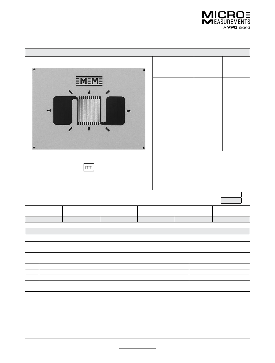
062AK
General Purpose Strain Gages—Linear Pattern
General Purpose Strain Gages—Linear Pattern
GAGE PATTERN DATA
actual size
GAGE
DESIGNATION
See Note 1
RESISTANCE
(OHMS)
See Note 2
OPTIONS
AVAILABLE
See Note 3
EA-XX-062AK-120
ED-DY-062AK-350
EP-08-062AK-120
120 ± 0.15%
350 ± 0.4%
120 ± 0.15%
E,
P
E
DESCRIPTION
General-purpose gage with elongated solder tabs.
See the 062AP pattern for WA, WK, and other series
with this grid size.
GAGE DIMENSIONS
Legend
ES = Each Section
CP = Complete Pattern
S = Section (S1 = Section 1)
M = Matrix
inch
millimeter
Gage Length
Overall Length
Grid Width
Overall Width
Matrix Length
Matrix Width
0.062
0.160
0.062
0.062
0.27
0.14
1.57
4.06
1.57
1.57
6.9
3.6
GAGE SERIES DATA
—
See Gage Series datasheet for complete specifications
Series
Description
Strain Range
Temperature Range
EA
Constantan foil in combination with a tough, flexible, polyimide backing.
±3%
–100° to +350°F (–75° to +175°C)
ED
Isoelastic foil in combination with tough, flexible polyimide film.
±2%
–320° to +400°F (–195° to +205°C)
EP
Annealed constantan foil with tough, high-elongation polyimide backing.
±10%
–100° to +400°F (–75° to +205°C)
Note 1:
Insert desired S-T-C number in spaces marked XX.
Note 2:
Tolerance is increased when Option W, E, SE, LE, or P is specified.
Note 3:
Products with designations and options shown in
bold
are not RoHS compliant.
For technical questions, contact
mm@vpgsensors.com
www.micro-measurements.com
26
Document No.: 11079
Revision: 22-Sep-2015
062AP
General Purpose Strain Gages—Linear Pattern
General Purpose Strain Gages—Linear Pattern
GAGE PATTERN DATA
actual size
GAGE
DESIGNATION
See Note 1, 3
RESISTANCE
(OHMS)
See Note 2
OPTIONS
AVAILABLE
See Note 3
EA-XX-062AP-120
ED-DY-062AP-350
EK-XX-062AP-350
WA-XX-062AP-120
WK-XX-062AP-350
EP-XX-062AP-120
SA-XX-062AP-120
SK-XX-062AP-350
SD-DY-062AP-350
WD-DY-062AP-350
120 ± 0.15%
350 ± 0.4%
350 ± 0.15%
120 ± 0.3%
350 ± 0.3%
120 ± 0.15%
120 ± 0.3%
350 ± 0.3%
350 ± 0.8%
350 ± 0.8%
W, E, L. LE,
P
E, L*, LE*
W,
SE
W*
W
*
DESCRIPTION
Widely used general-purpose gage. See also 062UW
pattern. EK-Series gages are supplied with duplex
copper pads (DP) when optional feature W or SE is
not specified.
GAGE DIMENSIONS
Legend
ES = Each Section
CP = Complete Pattern
S = Section (S1 = Section 1)
M = Matrix
inch
millimeter
Gage Length
Overall Length
Grid Width
Overall Width
Matrix Length
Matrix Width
0.062
0.114
0.062
0.062
0.26
0.16
1.57
2.90
1.57
1.57
6.6
4.1
GAGE SERIES DATA
—
See Gage Series datasheet for complete specifications
Series
Description
Strain Range
Temperature Range
EA
Constantan foil in combination with a tough, flexible, polyimide backing.
±3%
–100° to +350°F (–75° to +175°C)
ED
Isoelastic foil in combination with tough, flexible polyimide film.
±2%
–320° to +400°F (–195° to +205°C)
EK
K-alloy foil in combination with a tough, flexible polyimide backing.
±1.5%
–320° to +350°F (–195° to +175°C)
WA
Fully encapsulated constantan gages with high-endurance leadwires.
±2%
–100° to +400°F (–75° to +205°C)
WK
Fully encapsulated K-alloy gages with high-endurance leadwires.
±1.5%
–452° to +550°F (–269° to +290°C)
EP
Annealed constantan foil with tough, high-elongation polyimide backing.
±10%
–100° to +400°F (–75° to +205°C)
SA
Fully encapsulated constantan gages with solder dots.
±2%
–100° to +400°F (–75° to +205°C)
SK
Fully encapsulated K-alloy gages with solder dots.
±1.5%
–452° to +450°F (–269° to +230°C)
SD
Equivalent to WD Series, but with solder dots instead of leadwires.
±1.5%
–320° to +400°F (–195° to +205°C)
WD
Fully encapsulated isoelastic gages with high-endurance leadwires.
±1.5%
–320° to +500°F (–195° to +260°C)
Note 1:
Insert desired S-T-C number in spaces marked XX.
Note 2:
Tolerance is increased when Option W, E, SE, LE, or P is specified.
Note 3:
Products with designations and options shown in
bold
are not RoHS compliant.
*Options available but not normally recommended. See Optional Features data sheet for details.
For technical questions, contact
mm@vpgsensors.com
Document No.: 11080
Revision: 22-Sep-2015
www.micro-measurements.com
27
062AQ
General Purpose Strain Gages—Linear Pattern
General Purpose Strain Gages—Linear Pattern
GAGE PATTERN DATA
actual size
GAGE
DESIGNATION
See Note 1, 3
RESISTANCE
(OHMS)
See Note 2
OPTIONS
AVAILABLE
See Note 3
EA-XX-062AQ-350
ED-DY-062AQ-500
WA-XX-062AQ-350
WK-XX-062AQ-500
EP-08-062AQ-350
SA-XX-062AQ-350
SK-XX-062AQ-500
SD-DY-062AQ-500
WD-DY-062AQ-500
350 ± 0.15%
500 ± 0.4%
350 ± 0.3%
500 ± 0.3%
350 ± 0.15%
350 ± 0.3%
500 ± 0.3%
500 ± 0.8%
500 ± 0.8%
W, E, L, LE,
P
E, L*, LE*
W*
W
*
DESCRIPTION
General-purpose gage. Similar to 062AP pattern but
with high-resistance grid. See also 062UW pattern.
GAGE DIMENSIONS
Legend
ES = Each Section
CP = Complete Pattern
S = Section (S1 = Section 1)
M = Matrix
inch
millimeter
Gage Length
Overall Length
Grid Width
Overall Width
Matrix Length
Matrix Width
0.062
0.114
0.062
0.062
0.26
0.15
1.57
2.90
1.57
1.57
6.6
3.8
GAGE SERIES DATA
—
See Gage Series datasheet for complete specifications
Series
Description
Strain Range
Temperature Range
EA
Constantan foil in combination with a tough, flexible, polyimide backing.
±3%
–100° to +350°F (–75° to +175°C)
ED
Isoelastic foil in combination with tough, flexible polyimide film.
±2%
–320° to +400°F (–195° to +205°C)
WA
Fully encapsulated constantan gages with high-endurance leadwires.
±2%
–100° to +400°F (–75° to +205°C)
WK
Fully encapsulated K-alloy gages with high-endurance leadwires.
±1.5%
–452° to +550°F (–269° to +290°C)
EP
Annealed constantan foil with tough, high-elongation polyimide backing.
±10%
–100° to +400°F (–75° to +205°C)
SA
Fully encapsulated constantan gages with solder dots.
±2%
–100° to +400°F (–75° to +205°C)
SK
Fully encapsulated K-alloy gages with solder dots.
±1.5%
–452° to +450°F (–269° to +230°C)
SD
Equivalent to WD Series, but with solder dots instead of leadwires.
±1.5%
–320° to +400°F (–195° to +205°C)
WD
Fully encapsulated isoelastic gages with high-endurance leadwires.
±1.5%
–320° to +500°F (–195° to +260°C)
Note 1:
Insert desired S-T-C number in spaces marked XX.
Note 2:
Tolerance is increased when Option W, E, SE, LE, or P is specified.
Note 3:
Products with designations and options shown in
bold
are not RoHS compliant.
*Options available but not normally recommended. See Optional Features data sheet for details.
For technical questions, contact
mm@vpgsensors.com
www.micro-measurements.com
28
Document No.: 11093
Revision: 22-Sep-2015
062DN
General Purpose Strain Gages—Linear Pattern
General Purpose Strain Gages—Linear Pattern
GAGE PATTERN DATA
actual size
GAGE
DESIGNATION
See Note 1, 3
RESISTANCE
(OHMS)
See Note 2
OPTIONS
AVAILABLE
See Note 3
EA-XX-062DN-350
ED-DY-062DN-500
WA-XX-062DN-350
WK-XX-062DN-500
EP-08-062DN-350
SA-XX-062DN-350
SK-XX-062DN-500
SD-DY-062DMN-500
WD-DY-062DN-500
350 ± 0.15%
500 ± 0.4%
350 ± 0.3%
500 ± 0.3%
350 ± 0.15%
350 ± 0.3%
500 ± 0.3%
500 ± 0.8%
500 ± 0.8%
E, L, LE
E, L*, LE*
DESCRIPTION
Similar to 062DF pattern except for grid resistance.
GAGE DIMENSIONS
Legend
ES = Each Section
CP = Complete Pattern
S = Section (S1 = Section 1)
M = Matrix
inch
millimeter
Gage Length
Overall Length
Grid Width
Overall Width
Matrix Length
Matrix Width
0.062
0.190
0.062
0.062
0.34
0.18
1.57
4.83
1.57
1.57
8.6
4.6
GAGE SERIES DATA
—
See Gage Series datasheet for complete specifications
Series
Description
Strain Range
Temperature Range
EA
Constantan foil in combination with a tough, flexible, polyimide backing.
±3%
–100° to +350°F (–75° to +175°C)
ED
Isoelastic foil in combination with tough, flexible polyimide film.
±2%
–320° to +400°F (–195° to +205°C)
WA
Fully encapsulated constantan gages with high-endurance leadwires.
±2%
–100° to +400°F (–75° to +205°C)
WK
Fully encapsulated K-alloy gages with high-endurance leadwires.
±1.5%
–452° to +550°F (–269° to +290°C)
EP
Annealed constantan foil with tough, high-elongation polyimide backing.
±10%
–100° to +400°F (–75° to +205°C)
SA
Fully encapsulated constantan gages with solder dots.
±2%
–100° to +400°F (–75° to +205°C)
SK
Fully encapsulated K-alloy gages with solder dots.
±1.5%
–452° to +450°F (–269° to +230°C)
SD
Equivalent to WD Series, but with solder dots instead of leadwires.
±1.5%
–320° to +400°F (–195° to +205°C)
WD
Fully encapsulated isoelastic gages with high-endurance leadwires.
±1.5%
–320° to +500°F (–195° to +260°C)
Note 1:
Insert desired S-T-C number in spaces marked XX.
Note 2:
Tolerance is increased when Option W, E, SE, LE, or P is specified.
Note 3:
Products with designations and options shown in
bold
are not RoHS compliant.
*Options available but not normally recommended. See Optional Features data sheet for details.
For technical questions, contact
mm@vpgsensors.com
Document No.: 11329
Revision: 22-Sep-2015
www.micro-measurements.com
29
062ED
General Purpose Strain Gages—Linear Pattern
General Purpose Strain Gages—Linear Pattern
GAGE PATTERN DATA
actual size
GAGE
DESIGNATION
See Note 1, 3
RESISTANCE
(OHMS)
See Note 2
OPTIONS
AVAILABLE
See Note 3
EA-XX-062ED-120
ED-DY-062ED-350
WA-XX-062ED-120
WK-XX-062ED-350
EP-08-062ED-120
SA-XX-062ED-350
SK-XX-062ED-350
SD-DY-062ED-350
WD-DY-062ED-350
120 ± 0.15%
350 ± 0.4%
120 ± 0.3%
350 ± 0.3%
120 ± 0.15%
120 ± 0.3%
350 ± 0.3%
350 ± 0.8%
350 ± 0.8%
E, L, LE
E, L*, LE**
DESCRIPTION
General-purpose gage. Similar to 062EN pattern
except for grid resistance.
GAGE DIMENSIONS
Legend
ES = Each Section
CP = Complete Pattern
S = Section (S1 = Section 1)
M = Matrix
inch
millimeter
Gage Length
Overall Length
Grid Width
Overall Width
Matrix Length
Matrix Width
0.062
0.076
0.062
0.190
0.21
0.29
1.57
1.93
1.57
4.83
5.3
7.4
GAGE SERIES DATA
—
See Gage Series datasheet for complete specifications
Series
Description
Strain Range
Temperature Range
EA
Constantan foil in combination with a tough, flexible, polyimide backing.
±3%
–100° to +350°F (–75° to +175°C)
ED
Isoelastic foil in combination with tough, flexible polyimide film.
±2%
–320° to +400°F (–195° to +205°C)
WA
Fully encapsulated constantan gages with high-endurance leadwires.
±2%
–100° to +400°F (–75° to +205°C)
WK
Fully encapsulated K-alloy gages with high-endurance leadwires.
±1.5%
–452° to +550°F (–269° to +290°C)
EP
Annealed constantan foil with tough, high-elongation polyimide backing.
±10%
–100° to +400°F (–75° to +205°C)
SA
Fully encapsulated constantan gages with solder dots.
±2%
–100° to +400°F (–75° to +205°C)
SK
Fully encapsulated K-alloy gages with solder dots.
±1.5%
–452° to +450°F (–269° to +230°C)
SD
Equivalent to WD Series, but with solder dots instead of leadwires.
±1.5%
–320° to +400°F (–195° to +205°C)
WD
Fully encapsulated isoelastic gages with high-endurance leadwires.
±1.5%
–320° to +500°F (–195° to +260°C)
Note 1:
Insert desired S-T-C number in spaces marked XX.
Note 2:
Tolerance is increased when Option W, E, SE, LE, or P is specified.
Note 3:
Products with designations and options shown in
bold
are not RoHS compliant.
*Options available but not normally recommended. See Optional Features data sheet for details.
For technical questions, contact
mm@vpgsensors.com
www.micro-measurements.com
30
Document No.: 11094
Revision: 22-Sep-2015
062EN
General Purpose Strain Gages—Linear Pattern
General Purpose Strain Gages—Linear Pattern
GAGE PATTERN DATA
actual size
GAGE
DESIGNATION
See Note 1, 3
RESISTANCE
(OHMS)
See Note 2
OPTIONS
AVAILABLE
See Note 3
EA-XX-062EN-350
ED-DY-062EN-500
WA-XX-062EN-350
WK-XX-062EN-500
EP-08-062EN-350
SA-XX-062EN-350
SK-XX-062EN-500
SD-DY-062EN-500
WD-DY-062EN-500
350 ± 0.15%
500 ± 0.4%
350 ± 0.3%
500 ± 0.3%
350 ± 0.15%
350 ± 0.3%
500 ± 0.3%
500 ± 0.8%
500 ± 0.8%
E, L, LE
E, L*, LE*
DESCRIPTION
Similar to 062ED pattern except for grid resistance.
GAGE DIMENSIONS
Legend
ES = Each Section
CP = Complete Pattern
S = Section (S1 = Section 1)
M = Matrix
inch
millimeter
Gage Length
Overall Length
Grid Width
Overall Width
Matrix Length
Matrix Width
0.062
0.076
0.062
0.190
0.23
0.31
1.57
1.93
1.57
4.83
5.8
7.9
GAGE SERIES DATA
—
See Gage Series datasheet for complete specifications
Series
Description
Strain Range
Temperature Range
EA
Constantan foil in combination with a tough, flexible, polyimide backing.
±3%
–100° to +350°F (–75° to +175°C)
ED
Isoelastic foil in combination with tough, flexible polyimide film.
±2%
–320° to +400°F (–195° to +205°C)
WA
Fully encapsulated constantan gages with high-endurance leadwires.
±2%
–100° to +400°F (–75° to +205°C)
WK
Fully encapsulated K-alloy gages with high-endurance leadwires.
±1.5%
–452° to +550°F (–269° to +290°C)
EP
Annealed constantan foil with tough, high-elongation polyimide backing.
±10%
–100° to +400°F (–75° to +205°C)
SA
Fully encapsulated constantan gages with solder dots.
±2%
–100° to +400°F (–75° to +205°C)
SK
Fully encapsulated K-alloy gages with solder dots.
±1.5%
–452° to +450°F (–269° to +230°C)
SD
Equivalent to WD Series, but with solder dots instead of leadwires.
±1.5%
–320° to +400°F (–195° to +205°C)
WD
Fully encapsulated isoelastic gages with high-endurance leadwires.
±1.5%
–320° to +500°F (–195° to +260°C)
Note 1:
Insert desired S-T-C number in spaces marked XX.
Note 2:
Tolerance is increased when Option W, E, SE, LE, or P is specified.
Note 3:
Products with designations and options shown in
bold
are not RoHS compliant.
*Options available but not normally recommended. See Optional Features data sheet for details.
For technical questions, contact
mm@vpgsensors.com
Document No.: 11098
Revision: 22-Sep-2015
www.micro-measurements.com
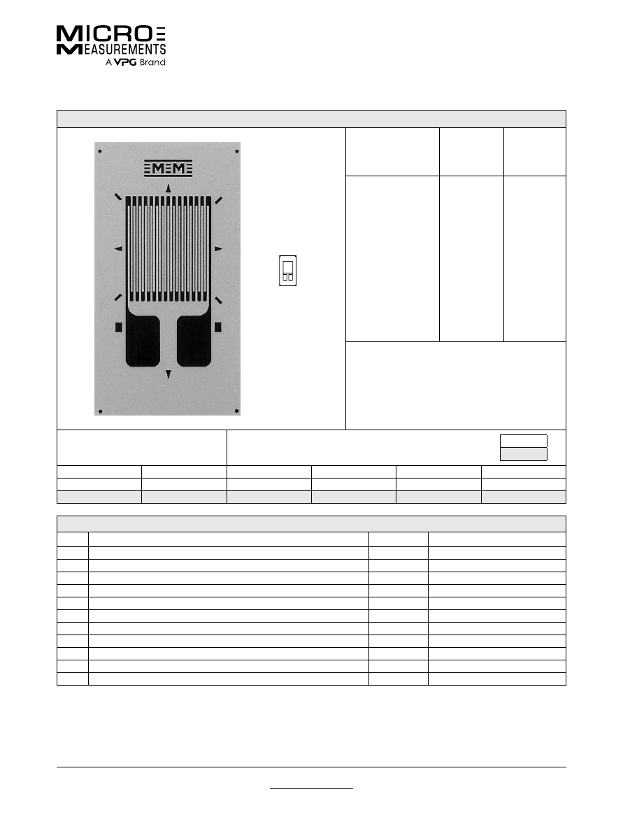
31
062LW
General Purpose Strain Gages—Linear Pattern
General Purpose Strain Gages—Linear Pattern
GAGE PATTERN DATA
actual size
GAGE
DESIGNATION
See Note 1
RESISTANCE
(OHMS)
OPTIONS
AVAILABLE
L2A-XX-062LW-120
L2A-XX-062LW-350
C2A-XX-062LW-120
C2A-XX-062LW-350
120 ± 0.6%
350 ± 0.6%
120 ± 0.6%
350 ± 0.6%
DESCRIPTION
Widely used general-purpose gage.
GAGE DIMENSIONS
Legend
ES = Each Section
CP = Complete Pattern
S = Section (S1 = Section 1)
M = Matrix
inch
millimeter
Gage Length
Overall Length
Grid Width
Overall Width
Matrix Length
Matrix Width
0.062
0.175
0.050
0.080
0.252
0.170
1.52
4.45
1.27
2.03
6.40
4.32
GAGE SERIES DATA
—
See Gage Series datasheet for complete specifications
Series
Description
Strain Range
Temperature Range
L2A
Encapsulated constantan gages with preattached ribbon leads.
±3%
–100° to +250°F (–75° to +120°C)
C2A
Encapsulated constantan gages with preattached ready-to-use cables.
±3%
–60° to +180°F (–50° to +80°C)
Note 1:
Insert desired S-T-C number in spaces marked XX.
Example of an
L2A Construction
Example of an
C2A Construction
For technical questions, contact
mm@vpgsensors.com
www.micro-measurements.com
32
Document No.: 11189
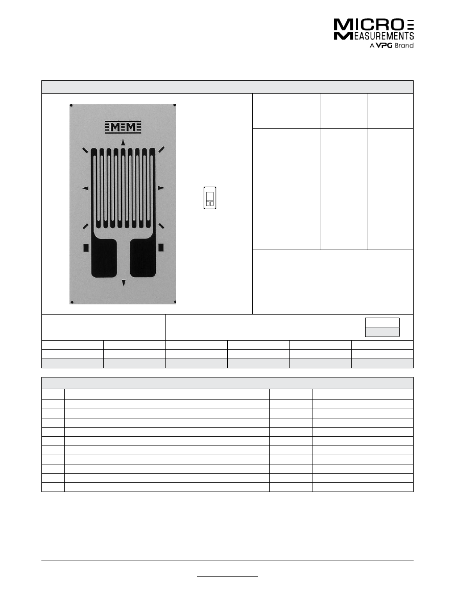
Revision: 22-Sep-2015
062UW
General Purpose Strain Gages—Linear Pattern
General Purpose Strain Gages—Linear Pattern
GAGE PATTERN DATA
actual size
GAGE
DESIGNATION
See Note 1
RESISTANCE
(OHMS)
OPTIONS
AVAILABLE
See Note 2
CEA-XX-062UW-120
CEA-XX-062UW-350
120 ± 0.3%
350 ± 0.3%
P2
P2
DESCRIPTION
General-purpose gage. Exposed solder tab area is
0.07 x 0.04 in [1.8 x 1.0 mm].
GAGE DIMENSIONS
Legend
ES = Each Section
CP = Complete Pattern
S = Section (S1 = Section 1)
M = Matrix
inch
millimeter
Gage Length
Overall Length
Grid Width
Overall Width
Matrix Length
Matrix Width
0.062
0.220
0.120
0.120
0.31
0.19
1.57
5.59
3.05
3.05
7.9
4.8
GAGE SERIES DATA
—
See Gage Series datasheet for complete specifications
Series
Description
Strain Range
Temperature Range
CEA
Universal general-purpose strain gages.
±3%
–100° to +350°F (–75° to +175°C)
Note 1:
Insert desired S-T-C number in spaces marked XX.
Note 2:
Products with designations and options shown in
bold
are not RoHS compliant.
For technical questions, contact
mm@vpgsensors.com
Document No.: 11193
Revision: 22-Sep-2015
www.micro-measurements.com
33
125AC
General Purpose Strain Gages—Linear Pattern
General Purpose Strain Gages—Linear Pattern
GAGE PATTERN DATA
actual size
GAGE
DESIGNATION
See Note 1, 3
RESISTANCE
(OHMS)
See Note 2
OPTIONS
AVAILABLE
See Note 3
EA-XX-125AC-350
ED-DY-125AC-10C
EK-XX-125AC-10C
S2K-XX-125AC-10C
WA-XX-125AC-350
WK-XX-125AC-10C
EP-08-125AC-350
SA-XX-125AC-350
SK-XX-125AC-10C
SD-DY-125AC-10C
WD-DY-125AC-10C
350 ± 0.15%
1000 ± 0.3%
1000 ± 0.15%
1000 ± 0.3%
350 ± 0.3%
1000 ± 0.3%
350 ± 0.15%
350 ± 0.3%
1000 ± 0.3%
1000 ± 0.6%
1000 ± 0.6%
W, E, L, LE,
P
E, L*, LE*
W, SE
W
*
W
*
DESCRIPTION
Widely used general-purpose gage with high-
resistance grid. See also 125AD, 125UN, and 125UW
patterns. EK-Series gages are supplied with duplex
copper pads (DP) when optional feature W or SE is
not specified.
GAGE DIMENSIONS
Legend
ES = Each Section
CP = Complete Pattern
S = Section (S1 = Section 1)
M = Matrix
inch
millimeter
Gage Length
Overall Length
Grid Width
Overall Width
Matrix Length
Matrix Width
0.125
0.250
0.125
0.125
0.40
0.22
3.18
6.35
3.18
3.18
10.2
5.6
GAGE SERIES DATA
—
See Gage Series datasheet for complete specifications
Series
Description
Strain Range
Temperature Range
EA
Constantan foil in combination with a tough, flexible, polyimide backing.
±5%
–100° to +350°F (–75° to +175°C)
ED
Isoelastic foil in combination with tough, flexible polyimide film.
±2%
–320° to +400°F (–195° to +205°C)
EK
K-alloy foil in combination with a tough, flexible polyimide backing.
±1.5%
–320° to +350°F (–195° to +175°C)
S2K
K-alloy foil with laminated thick, high-performance polyimide backing.
±1.5%
–100° to +250°F (–75° to +120°C)
WA
Fully encapsulated constantan gages with high-endurance leadwires.
±2%
–100° to +400°F (–75° to +205°C)
WK
Fully encapsulated K-alloy gages with high-endurance leadwires.
±1.5%
–452° to +550°F (–269° to +290°C)
EP
Annealed constantan foil with tough, high-elongation polyimide backing.
±20%
–100° to +400°F (–75° to +205°C)
SA
Fully encapsulated constantan gages with solder dots.
±2%
–100° to +400°F (–75° to +205°C)
SK
Fully encapsulated K-alloy gages with solder dots.
±1.5%
–452° to +450°F (–269° to +230°C)
SD
Equivalent to WD Series, but with solder dots instead of leadwires.
±1.5%
–320° to +400°F (–195° to +205°C)
WD
Fully encapsulated isoelastic gages with high-endurance leadwires.
±1.5%
–320° to +500°F (–195° to +260°C)
Note 1:
Insert desired S-T-C number in spaces marked XX.
Note 2:
Tolerance is increased when Option W, E, SE, LE, or P is specified.
Note 3:
Products with designations and options shown in
bold
are not RoHS compliant.
*Options available but not normally recommended. See Optional Features data sheet for details.
For technical questions, contact
mm@vpgsensors.com
www.micro-measurements.com
34
Document No.: 11194
Revision: 22-Sep-2015
125AD
General Purpose Strain Gages—Linear Pattern
General Purpose Strain Gages—Linear Pattern
GAGE PATTERN DATA
actual size
GAGE
DESIGNATION
See Note 1, 3
RESISTANCE
(OHMS)
See Note 2
OPTIONS
AVAILABLE
See Note 3
EA-XX-125AD-120
ED-DY-125AD-350
EK-XX-125AD-350
WA-XX-125AD-120
WK-XX-125AD-350
EP-XX-125AD-120
SA-XX-125AD-120
SK-XX-125AD-350
SD-DY-125AD-350
WD-DY-125AD-350
120 ± 0.15%
350 ± 0.3%
350 ± 0.15%
120 ± 0.3%
350 ± 0.3%
120 ± 0.15%
120 ± 0.3%
350 ± 0.3%
350 ± 0.6%
350 ± 0.6%
W, E, L, LE,
P
E, L*, LE*
W,
SE
W*
W
*
DESCRIPTION
Widely used general-purpose gage. EK-Series gages
are supplied with duplex copper pads (DP) when
optional feature W or SE is not specified.
GAGE DIMENSIONS
Legend
ES = Each Section
CP = Complete Pattern
S = Section (S1 = Section 1)
M = Matrix
inch
millimeter
Gage Length
Overall Length
Grid Width
Overall Width
Matrix Length
Matrix Width
0.125
0.250
0.125
0.125
0.40
0.22
3.18
6.35
3.18
3.18
10.2
5.6
GAGE SERIES DATA
—
See Gage Series datasheet for complete specifications
Series
Description
Strain Range
Temperature Range
EA
Constantan foil in combination with a tough, flexible, polyimide backing.
±5%
–100° to +350°F (–75° to +175°C)
ED
Isoelastic foil in combination with tough, flexible polyimide film.
±2%
–320° to +400°F (–195° to +205°C)
EK
K-alloy foil in combination with a tough, flexible polyimide backing.
±1.5%
–320° to +350°F (–195° to +175°C)
WA
Fully encapsulated constantan gages with high-endurance leadwires.
±2%
–100° to +400°F (–75° to +205°C)
WK
Fully encapsulated K-alloy gages with high-endurance leadwires.
±1.5%
–452° to +550°F (–269° to +290°C)
EP
Annealed constantan foil with tough, high-elongation polyimide backing.
±20%
–100° to +400°F (–75° to +205°C)
SA
Fully encapsulated constantan gages with solder dots.
±2%
–100° to +400°F (–75° to +205°C)
SK
Fully encapsulated K-alloy gages with solder dots.
±1.5%
–452° to +450°F (–269° to +230°C)
SD
Equivalent to WD Series, but with solder dots instead of leadwires.
±1.5%
–320° to +400°F (–195° to +205°C)
WD
Fully encapsulated isoelastic gages with high-endurance leadwires.
±1.5%
–320° to +500°F (–195° to +260°C)
Note 1:
Insert desired S-T-C number in spaces marked XX.
Note 2:
Tolerance is increased when Option W, E, SE, LE, or P is specified.
Note 3:
Products with designations and options shown in
bold
are not RoHS compliant.
*Options available but not normally recommended. See Optional Features data sheet for details.

For technical questions, contact
mm@vpgsensors.com
Document No.: 11195
Revision: 22-Sep-2015
www.micro-measurements.com
35
125BB
General Purpose Strain Gages—Linear Pattern
General Purpose Strain Gages—Linear Pattern
GAGE PATTERN DATA
actual size
GAGE
DESIGNATION
See Note 1, 3
RESISTANCE
(OHMS)
See Note 2
OPTIONS
AVAILABLE
See Note 3
EA-XX-125BB-120
ED-DY-125BB-350
WA-XX-125BB-120
WK-XX-125BB-350
EP-08-125BB-120
SA-XX-125BB-120
SK-XX-125BB-350
SD-DY-125BB-350
WD-DY-125BB-350
120 ± 0.15%
350 ± 0.3%
120 ± 0.3%
350 ± 0.3%
120 ± 0.15%
120 ± 0.3%
350 ± 0.3%
350 ± 0.6%
350 ± 0.6%
E,
P
E
DESCRIPTION
Narrow general-purpose gage with extended tabs.
GAGE DIMENSIONS
Legend
ES = Each Section
CP = Complete Pattern
S = Section (S1 = Section 1)
M = Matrix
inch
millimeter
Gage Length
Overall Length
Grid Width
Overall Width
Matrix Length
Matrix Width
0.125
0.245
0.088
0.088
0.43
0.22
3.18
6.22
2.24
2.24
10.9
5.6
GAGE SERIES DATA
—
See Gage Series datasheet for complete specifications
Series
Description
Strain Range
Temperature Range
EA
Constantan foil in combination with a tough, flexible, polyimide backing.
±5%
–100° to +350°F (–75° to +175°C)
ED
Isoelastic foil in combination with tough, flexible polyimide film.
±2%
–320° to +400°F (–195° to +205°C)
WA
Fully encapsulated constantan gages with high-endurance leadwires.
±2%
–100° to +400°F (–75° to +205°C)
WK
Fully encapsulated K-alloy gages with high-endurance leadwires.
±1.5%
–452° to +550°F (–269° to +290°C)
EP
Annealed constantan foil with tough, high-elongation polyimide backing.
±20%
–100° to +400°F (–75° to +205°C)
SA
Fully encapsulated constantan gages with solder dots.
±2%
–100° to +400°F (–75° to +205°C)
SK
Fully encapsulated K-alloy gages with solder dots.
±1.5%
–452° to +450°F (–269° to +230°C)
SD
Equivalent to WD Series, but with solder dots instead of leadwires.
±1.5%
–320° to +400°F (–195° to +205°C)
WD
Fully encapsulated isoelastic gages with high-endurance leadwires.
±1.5%
–320° to +500°F (–195° to +260°C)
Note 1:
Insert desired S-T-C number in spaces marked XX.
Note 2:
Tolerance is increased when Option W, E, SE, LE, or P is specified.
Note 3:
Products with designations and options shown in
bold
are not RoHS compliant.
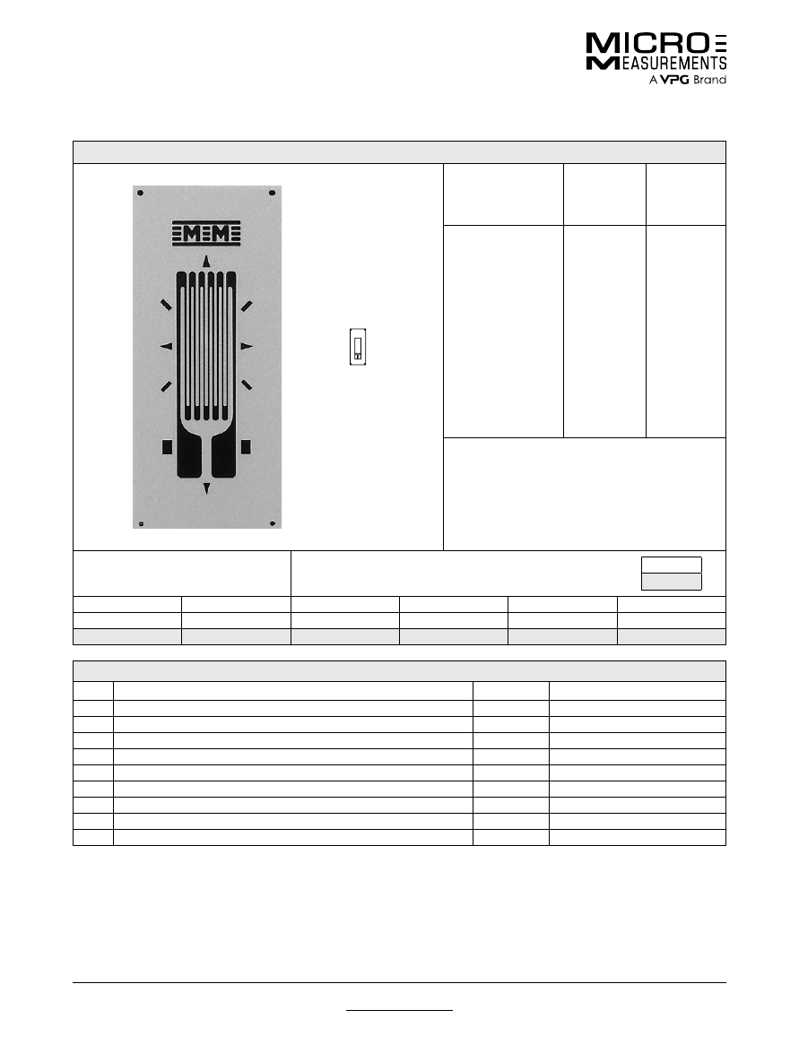
For technical questions, contact
mm@vpgsensors.com
www.micro-measurements.com
36
Document No.: 11196
Revision: 22-Sep-2015
125BT
General Purpose Strain Gages—Linear Pattern
General Purpose Strain Gages—Linear Pattern
GAGE PATTERN DATA
actual size
GAGE
DESIGNATION
See Note 1, 3
RESISTANCE
(OHMS)
See Note 2
OPTIONS
AVAILABLE
See Note 3
EA-XX-125BT-120
ED-DY-125BT-350
WA-XX-125BT-120
WK-XX-125BT-350
EP-08-125BT-120
SA-XX-125BT-120
SK-XX-125BT-350
SD-DY-125BT-350
WD-DY-125BT-350
120 ± 0.15%
350 ± 0.3%
120 ± 0.3%
350 ± 0.3%
120 ± 0.15%
120 ± 0.3%
350 ± 0.3%
350 ± 0.6%
350 ± 0.6%
W, E, L, LE,
P
E, L*, LE*
W*
W
*
DESCRIPTION
General-purpose gage with narrow grid and compact
geometry. See also 125BZ pattern.
GAGE DIMENSIONS
Legend
ES = Each Section
CP = Complete Pattern
S = Section (S1 = Section 1)
M = Matrix
inch
millimeter
Gage Length
Overall Length
Grid Width
Overall Width
Matrix Length
Matrix Width
0.125
0.215
0.062
0.062
0.37
0.16
3.18
5.46
1.57
1.57
9.4
4.1
GAGE SERIES DATA
—
See Gage Series datasheet for complete specifications
Series
Description
Strain Range
Temperature Range
EA
Constantan foil in combination with a tough, flexible, polyimide backing.
±5%
–100° to +350°F (–75° to +175°C)
ED
Isoelastic foil in combination with tough, flexible polyimide film.
±2%
–320° to +400°F (–195° to +205°C)
WA
Fully encapsulated constantan gages with high-endurance leadwires.
±2%
–100° to +400°F (–75° to +205°C)
WK
Fully encapsulated K-alloy gages with high-endurance leadwires.
±1.5%
–452° to +550°F (–269° to +290°C)
EP
Annealed constantan foil with tough, high-elongation polyimide backing.
±20%
–100° to +400°F (–75° to +205°C)
SA
Fully encapsulated constantan gages with solder dots.
±2%
–100° to +400°F (–75° to +205°C)
SK
Fully encapsulated K-alloy gages with solder dots.
±1.5%
–452° to +450°F (–269° to +230°C)
SD
Equivalent to WD Series, but with solder dots instead of leadwires.
±1.5%
–320° to +400°F (–195° to +205°C)
WD
Fully encapsulated isoelastic gages with high-endurance leadwires.
±1.5%
–320° to +500°F (–195° to +260°C)
Note 1:
Insert desired S-T-C number in spaces marked XX.
Note 2:
Tolerance is increased when Option W, E, SE, LE, or P is specified.
Note 3:
Products with designations and options shown in
bold
are not RoHS compliant.
*Options available but not normally recommended. See Optional Features data sheet for details.
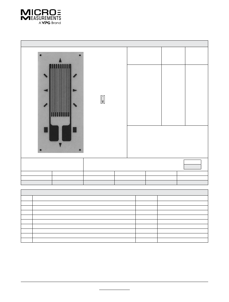
For technical questions, contact
mm@vpgsensors.com
Document No.: 11197
www.micro-measurements.com
37
125BZ
General Purpose Strain Gages—Linear Pattern
General Purpose Strain Gages—Linear Pattern
Document No.: 11197
Revision: 22-Sep-2015
GAGE PATTERN DATA
actual size
GAGE
DESIGNATION
See Note 1, 3
RESISTANCE
(OHMS)
See Note 2
OPTIONS
AVAILABLE
See Note 3
EA-XX-125BZ-350
ED-DY-125BZ-10C
EK-XX-125BZ-10C
WA-XX-125BZ-350
WK-XX-125BZ-10C
SA-XX-125BZ-350
SK-XX-125BZ-10C
SD-DY-125BZ-10C
WD-DY-125BZ-10C
350 ± 0.15%
1000 ± 0.4%
1000 ± 0.15%
350 ± 0.3%
1000 ± 0.3%
350 ± 0.3%
1000 ± 0.3%
1000 ± 0.8%
1000 ± 0.8%
W, E, L, LE,
P
E, L*, LE*
W*
W*
DESCRIPTION
Narrow high-resistance gage with compact geometry.
Similar to 125BT pattern except for grid resistance.
EK-Series gages are supplied with duplex copper
dots(DD) when optional feature W is not specified.
GAGE DIMENSIONS
Legend
ES = Each Section
CP = Complete Pattern
S = Section (S1 = Section 1)
M = Matrix
inch
millimeter
Gage Length
Overall Length
Grid Width
Overall Width
Matrix Length
Matrix Width
0.125
0.220
0.062
0.062
0.29
0.13
3.18
5.59
1.57
1.57
7.4
3.3
GAGE SERIES DATA
—
See Gage Series datasheet for complete specifications
Series
Description
Strain Range
Temperature Range
EA
Constantan foil in combination with a tough, flexible, polyimide backing.
±5%
–100° to +350°F (–75° to +175°C)
ED
Isoelastic foil in combination with tough, flexible polyimide film.
±2%
–320° to +400°F (–195° to +205°C)
EK
K-alloy foil in combination with a tough, flexible polyimide backing.
±1.5%
–320° to +350°F (–195° to +175°C)
WA
Fully encapsulated constantan gages with high-endurance leadwires.
±2%
–100° to +400°F (–75° to +205°C)
WK
Fully encapsulated K-alloy gages with high-endurance leadwires.
±1.5%
–452° to +550°F (–269° to +290°C)
SA
Fully encapsulated constantan gages with solder dots.
±2%
–100° to +400°F (–75° to +205°C)
SK
Fully encapsulated K-alloy gages with solder dots.
±1.5%
–452° to +450°F (–269° to +230°C)
SD
Equivalent to WD Series, but with solder dots instead of leadwires.
±1.5%
–320° to +400°F (–195° to +205°C)
WD
Fully encapsulated isoelastic gages with high-endurance leadwires.
±1.5%
–320° to +500°F (–195° to +260°C)
Note 1:
Insert desired S-T-C number in spaces marked XX.
Note 2:
Tolerance is increased when Option W, E, SE, LE, or P is specified.
Note 3:
Products with designations and options shown in
bold
are not RoHS compliant.
*Options available but not normally recommended. See Optional Features data sheet for details.
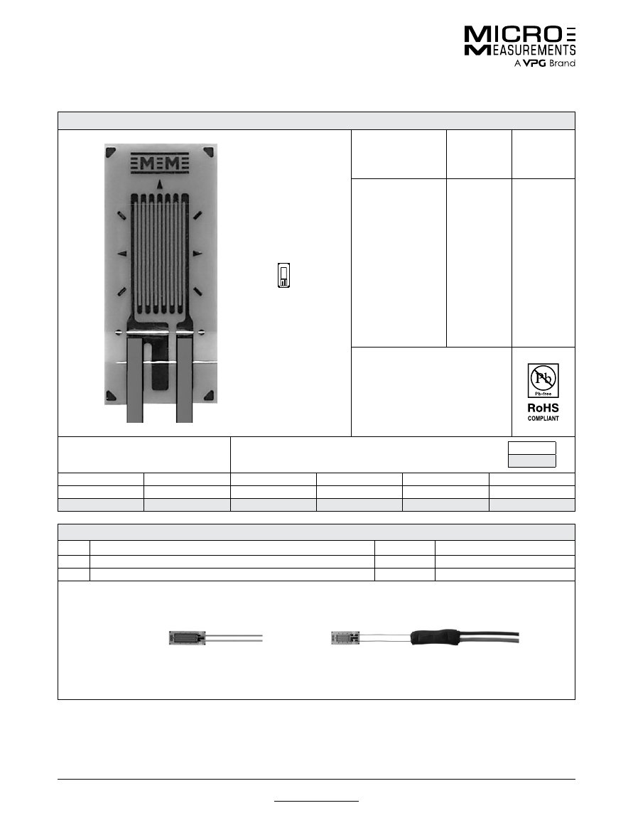
For technical questions, contact
mm@vpgsensors.com
www.micro-measurements.com
38
Document No.: 11200
Revision: 22-Sep-2015
125LW
General Purpose Strain Gages—Linear Pattern
General Purpose Strain Gages—Linear Pattern
GAGE PATTERN DATA
actual size
GAGE
DESIGNATION
See Note 1
RESISTANCE
(OHMS)
OPTIONS
AVAILABLE
L2A-XX-125LW-120
L2A-XX-125LW-350
C2A-XX-125LW-120
C2A-XX-125LW-350
120 ± 0.6%
350 ± 0.6%
120 ± 0.6%
350 ± 0.6%
DESCRIPTION
Widely used general-purpose gage.
GAGE DIMENSIONS
Legend
ES = Each Section
CP = Complete Pattern
S = Section (S1 = Section 1)
M = Matrix
inch
millimeter
Gage Length
Overall Length
Grid Width
Overall Width
Matrix Length
Matrix Width
0.125
0.238
0.070
0.080
0.315
0.170
3.18
6.05
1.78
2.03
8.00
4.32
GAGE SERIES DATA
—
See Gage Series datasheet for complete specifications
Series
Description
Strain Range
Temperature Range
L2A
Encapsulated constantan gages with preattached ribbon leads.
±3%
–100° to +250°F (–75° to +120°C)
C2A
Encapsulated constantan gages with preattached ready-to-use cables.
±3%
–60° to +180°F (–50° to +80°C)
Note 1:
Insert desired S-T-C number in spaces marked XX.
Example of an
L2A Construction
Example of an
C2A Construction
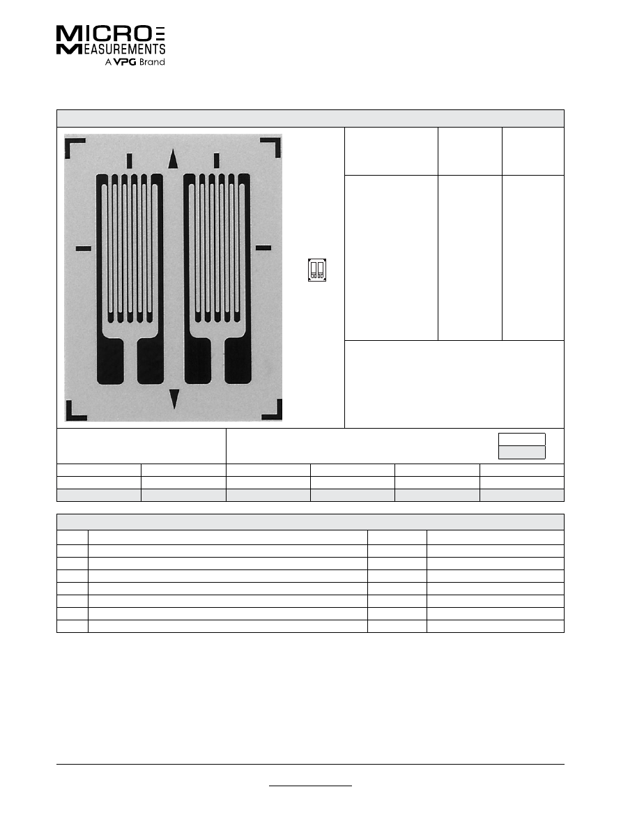
For technical questions, contact
mm@vpgsensors.com
Document No.: 11207
Revision: 22-Sep-2015
www.micro-measurements.com
39
125PC
General Purpose Strain Gages—Linear Pattern
General Purpose Strain Gages—Linear Pattern
GAGE PATTERN DATA
actual size
GAGE
DESIGNATION
See Note 1, 3
RESISTANCE
(OHMS)
See Note 2
OPTIONS
AVAILABLE
See Note 3
EA-XX-125PC-120
EA-XX-125PC-350
ED-DY-125PC-350
ED-DY-125PC-10C
EK-XX-125PC-10C
WA-XX-125PC-120
WA-XX-125PC-350
WK-XX-125PC-350
WK-XX-125PC-10C
SA-XX-125PC-120
SA-XX-125PC-350
SK-XX-125PC-350
SK-XX-125PC-10C
120 ± 0.2%
350 ± 0.2%
350 ± 0.4%
1000 ± 0.4%
1000 ± 0.2%
120 ± 0.4%
350 ± 0.4%
350 ± 0.4%
1000 ± 0.4%
120 ± 0.4%
350 ± 0.4%
350 ± 0.4%
1000 ± 0.4%
W, E, L, LE
W, E, L, LE
E
E
W, SE
W*
W*
W*
W*
DESCRIPTION
Dual-pattern gage for use in back-to-back bending
applications. Longitudinal grid centerlines spaced
0.085 in [2.16 mm] apart. See also 125MG pattern.
EK-Series gages are supplied with duplex copper
pads (DP) when optional W or SE is not specified.
GAGE DIMENSIONS
Legend
ES = Each Section
CP = Complete Pattern
S = Section (S1 = Section 1)
M = Matrix
inch
millimeter
Gage Length
Overall Length
Grid Width
Overall Width
Matrix Length
Matrix Width
0.125 ES
0.205 CP
0.065 ES
0.150 CP
0.29
0.23
3.18 ES
5.21 CP
1.65 ES
3.81 CP
7.4
5.8
GAGE SERIES DATA
—
See Gage Series datasheet for complete specifications
Series
Description
Strain Range
Temperature Range
EA
Constantan foil in combination with a tough, flexible, polyimide backing.
±5%
–100° to +350°F (–75° to +175°C)
ED
Isoelastic foil in combination with tough, flexible polyimide film.
±2%
–320° to +400°F (–195° to +205°C)
EK
K-alloy foil in combination with a tough, flexible polyimide backing.
±1.5%
–320° to +350°F (–195° to +175°C)
WA
Fully encapsulated constantan gages with high-endurance leadwires.
±2%
–100° to +400°F (–75° to +205°)
WK
Fully encapsulated K-alloy gages with high-endurance leadwires.
±1.5%
–452° to +550°F (–269° to +290°C)
SA
Fully encapsulated constantan gages with solder dots.
±2%
–100° to +400°F (–75° to +205°C)
SK
Fully encapsulated K-alloy gages with solder dots.
±1.5%
–452° to +450°F (–269° to +230°C)
Note 1:
Insert desired S-T-C number in spaces marked XX.
Note 2:
Tolerance is increased when Option W, E, SE, LE, or P is specified.
Note 3:
Products with designations and options shown in
bold
are not RoHS compliant.
*Options available but not normally recommended. See Optional Features datasheet for details.
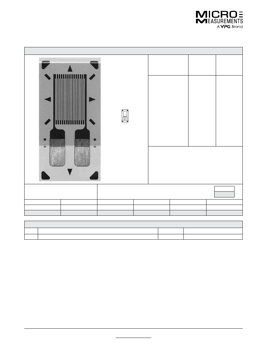
For technical questions, contact
mm@vpgsensors.com
www.micro-measurements.com
40
Document No.: 11224
Revision: 25-Aug-2015
125UN
General Purpose Strain Gages—Linear Pattern
General Purpose Strain Gages—Linear Pattern
GAGE PATTERN DATA
actual size
GAGE
DESIGNATION
See Note 1
RESISTANCE
(OHMS)
OPTIONS
AVAILABLE
See Note 2
CEA-XX-125UN-120
CEA-XX-125UN-350
120 ± 0.3%
350 ± 0.3%
P2
P2
DESCRIPTION
General-purpose gage with narrow geometry. Exposed
solder tab area 0.06 x 0.05 in (1.5 x 1.1 mm). See also
125UW pattren.
GAGE DIMENSIONS
Legend
ES = Each Section
CP = Complete Pattern
S = Section (S1 = Section 1)
M = Matrix
inch
millimeter
Gage Length
Overall Length
Grid Width
Overall Width
Matrix Length
Matrix Width
0.125
0.275
0.100
0.120
0.38
0.19
3.18
6.99
2.54
3.05
9.7
4.8
GAGE SERIES DATA
—
See Gage Series datasheet for complete specifications
Series
Description
Strain Range
Temperature Range
CEA
Universal general-purpose strain gages.
±5%
–100° to +350°F (–75° to +175°C)
Note 1:
Insert desired S-T-C number in spaces marked XX.
Note 2:
Products with designations and options shown in bold are not RoHS compliant.
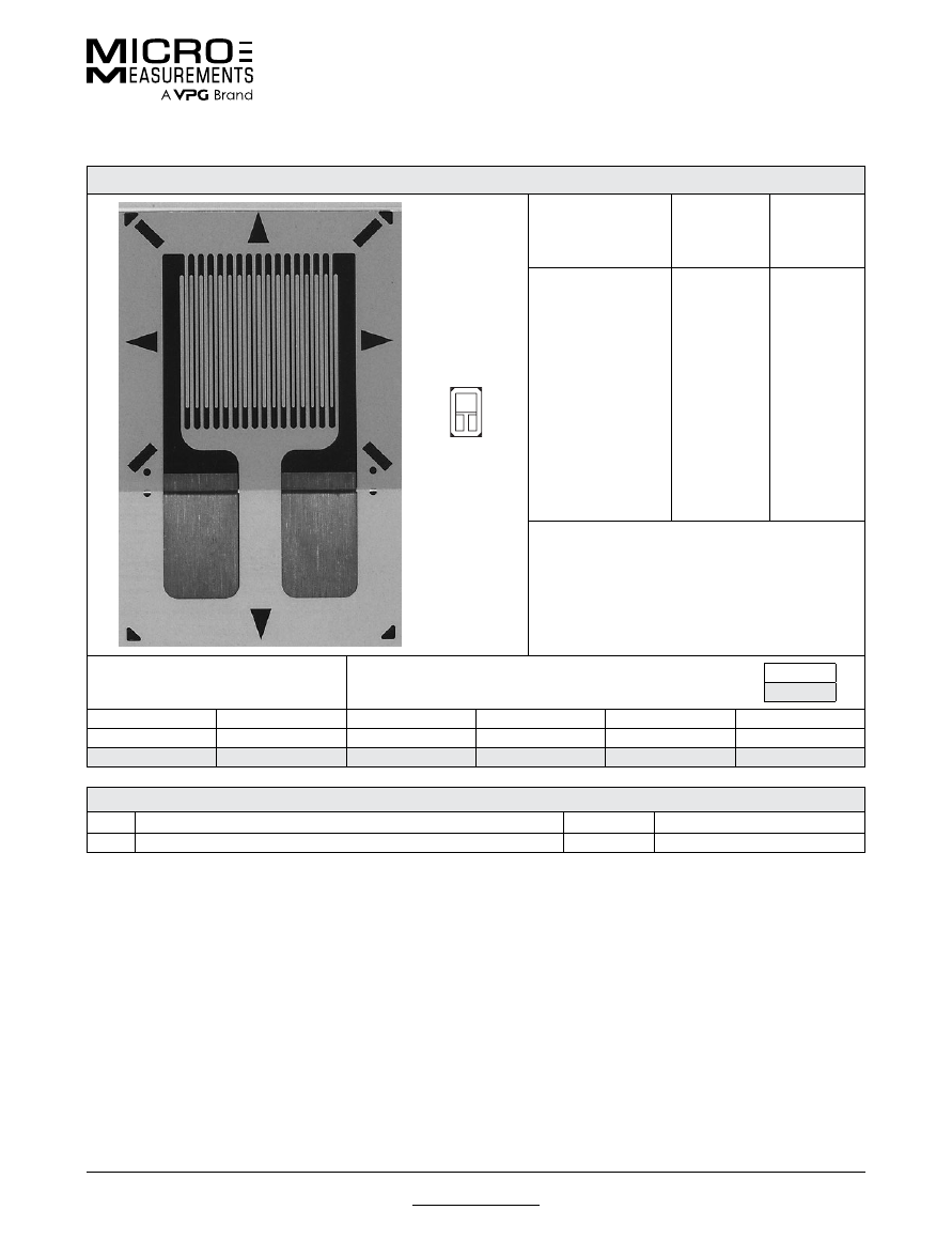
For technical questions, contact
mm@vpgsensors.com
Document No.: 11241
Revision: 25-Aug-2015
www.micro-measurements.com
41
125UW
General Purpose Strain Gages—Linear Pattern
General Purpose Strain Gages—Linear Pattern
GAGE PATTERN DATA
actual size
GAGE
DESIGNATION
See Note 1
RESISTANCE
(OHMS)
OPTIONS
AVAILABLE
See Note 2
CEA-XX-125UW-120
CEA-XX-125UW-350
120 ± 0.3%
350 ± 0.3%
P2
P2
DESCRIPTION
General-purpose gage. Exposed solder tab area
0.10 x 0.07 (2.5 x 1.8 mm). See also 125UN pattern.
GAGE DIMENSIONS
Legend
ES = Each Section
CP = Complete Pattern
S = Section (S1 = Section 1)
M = Matrix
inch
millimeter
Gage Length
Overall Length
Grid Width
Overall Width
Matrix Length
Matrix Width
0.125
0.325
0.180
0.180
0.42
0.27
3.18
8.26
4.57
4.57
10.7
6.9
GAGE SERIES DATA
—
See Gage Series datasheet for complete specifications
Series
Description
Strain Range
Temperature Range
CEA
Universal general-purpose strain gages.
±5%
–100° to +350°F (–75° to +175°C)
Note 1:
Insert desired S-T-C number in spaces marked XX.
Note 2:
Products with designations and options shown in bold are not RoHS compliant.
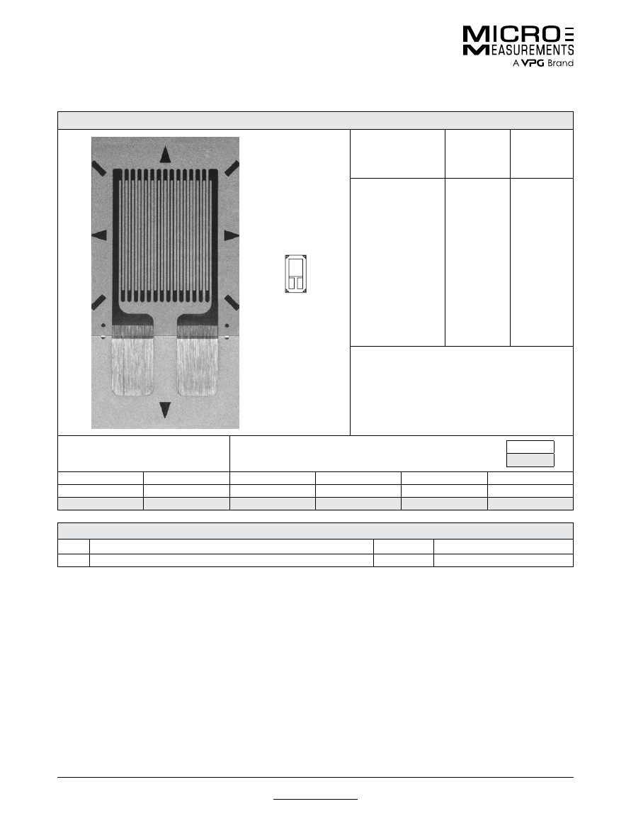
For technical questions, contact
mm@vpgsensors.com
www.micro-measurements.com
42
Document No.: 11332
Revision: 22-Sep-2015
187UW
General Purpose Strain Gages—Linear Pattern
General Purpose Strain Gages—Linear Pattern
GAGE PATTERN DATA
actual size
GAGE
DESIGNATION
See Note 1
RESISTANCE
(OHMS)
OPTIONS
AVAILABLE
See Note 2
CEA-XX-187UW-120
CEA-XX-187UW-350
120 ± 0.3%
350 ± 0.3%
P2
P2
DESCRIPTION
General-purpose gage. Exposed solder tab area
0.10 x 0.07 in (2.5 x 1.8 mm).
GAGE DIMENSIONS
Legend
ES = Each Section
CP = Complete Pattern
S = Section (S1 = Section 1)
M = Matrix
inch
millimeter
Gage Length
Overall Length
Grid Width
Overall Width
Matrix Length
Matrix Width
0.187
0.387
0.180
0.180
0.49
0.27
4.75
9.83
4.57
4.57
12.4
6.9
GAGE SERIES DATA
—
See Gage Series datasheet for complete specifications
Series
Description
Strain Range
Temperature Range
CEA
Universal general-purpose strain gages.
±5%
–100° to +350°F (–75° to +175°C)
Note 1:
Insert desired S-T-C number in spaces marked XX.
Note 2:
Products with designations and options shown in
bold
are not RoHS compliant.
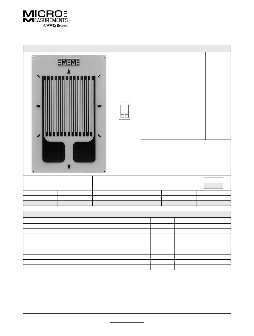
For technical questions, contact
mm@vpgsensors.com
Document No.: 11292
Revision: 22-Sep-2015
www.micro-measurements.com
43
250AE
General Purpose Strain Gages—Linear Pattern
General Purpose Strain Gages—Linear Pattern
GAGE PATTERN DATA
actual size
GAGE
DESIGNATION
See Note 1, 3
RESISTANCE
(OHMS)
See Note 2
OPTIONS
AVAILABLE
See Note 3
EA-XX-250AE-350
ED-DY-250AE-10C
WA-XX-250AE-350
WK-XX-250AE-10C
EP-08-250AE-350
SA-XX-250AE-350
SK-XX-250AE-10C
SD-DY-250AE-10C
WD-DY-250AE-10C
350 ± 0.15%
1000 ± 0.3%
350 ± 0.3%
1000 ± 0.3%
350 ± 0.15%
350 ± 0.3%
1000 ± 0.3%
1000 ± 0.6%
1000 ± 0.6%
W, E, L, LE,
P
E, L*, LE*
W*
W*
DESCRIPTION
General-purpose gage with high-dissipation grid. See
also 250AF pattern.
GAGE DIMENSIONS
Legend
ES = Each Section
CP = Complete Pattern
S = Section (S1 = Section 1)
M = Matrix
inch
millimeter
Gage Length
Overall Length
Grid Width
Overall Width
Matrix Length
Matrix Width
0.250
0.415
0.250
0.250
0.57
0.36
6.35
10.54
6.35
6.35
14.5
9.1
GAGE SERIES DATA
—
See Gage Series datasheet for complete specifications
Series
Description
Strain Range
Temperature Range
EA
Constantan foil in combination with a tough, flexible, polyimide backing.
±5%
–100° to +350°F (–75° to +175°C)
ED
Isoelastic foil in combination with tough, flexible polyimide film.
±2%
–320° to +400°F (–195° to +205°C)
WA
Fully encapsulated constantan gages with high-endurance leadwires.
±2%
–100° to +400°F (–75° to +205°)
WK
Fully encapsulated K-alloy gages with high-endurance leadwires.
±1.5%
–452° to +550°F (–269° to +290°C)
EP
Annealed constantan foil with tough, high-elongation polyimide backing.
±20%
–100° to +400°F (–75° to +205°C)
SA
Fully encapsulated constantan gages with solder dots.
±2%
–100° to +400°F (–75° to +205°C)
SK
Fully encapsulated K-alloy gages with solder dots.
±1.5%
–452° to +450°F (–269° to +230°C)
SD
Equivalent to WD Series, but with solder dots instead of leadwires.
±1.5%
–320° to +400°F (–195° to +205°C)
WD
Fully encapsulated isoelastic gages with high-endurance leadwires.
±1.5%
–320° to +500°F (–195° to +260°C)
Note 1:
Insert desired S-T-C number in spaces marked XX.
Note 2:
Tolerance is increased when Option W, E, SE, LE, or P is specified.
Note 3:
Products with designations and options shown in
bold
are not RoHS compliant.
*Options available but not normally recommended. See Optional Features datasheet for details.
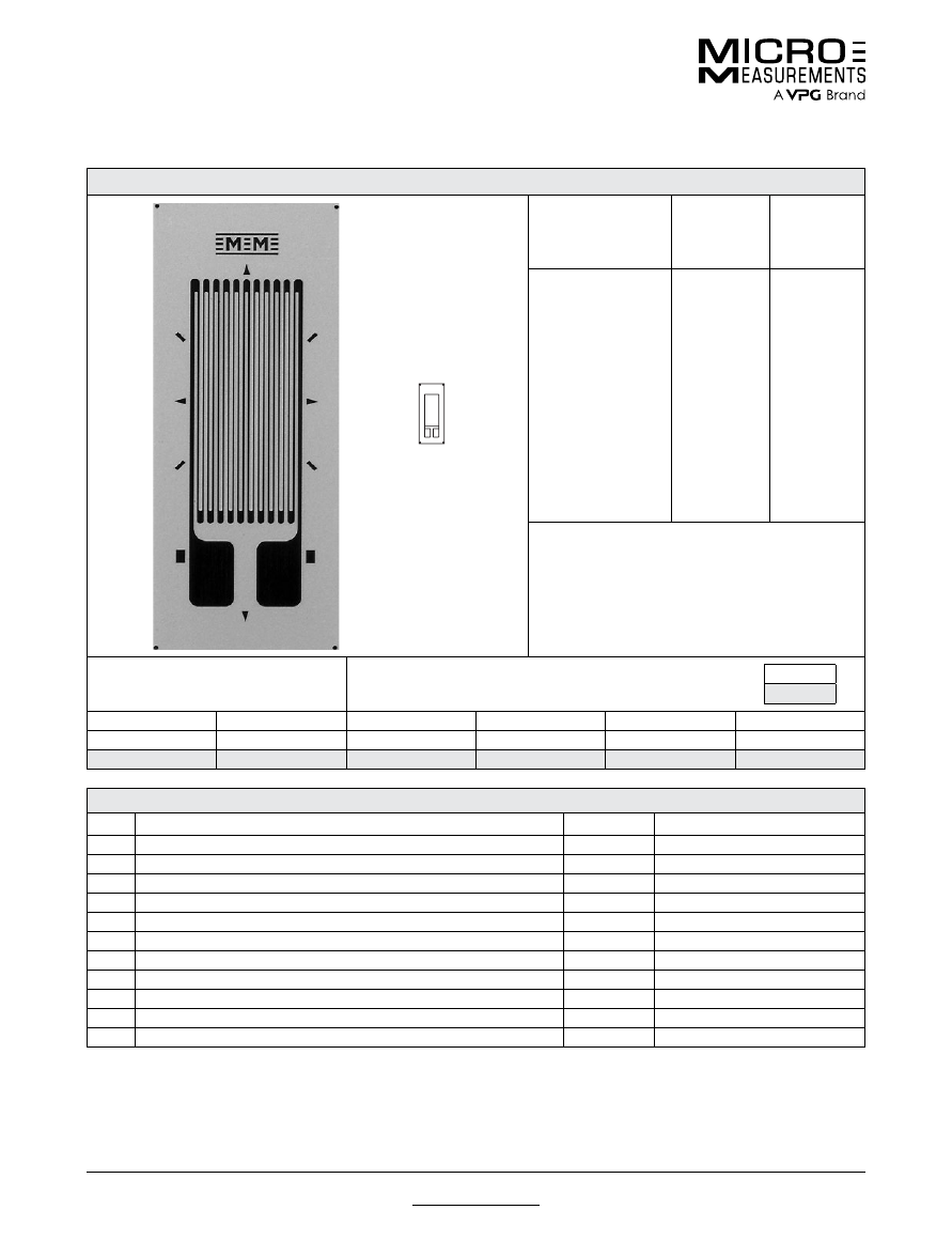
For technical questions, contact
mm@vpgsensors.com
www.micro-measurements.com
44
Document No.: 11293
Revision: 22-Sep-2015
250BF
General Purpose Strain Gages—Linear Pattern
General Purpose Strain Gages—Linear Pattern
GAGE PATTERN DATA
actual size
GAGE
DESIGNATION
See Note 1, 3
RESISTANCE
(OHMS)
See Note 2
OPTIONS
AVAILABLE
See Note 3
EA-XX-250BF-350
ED-DY-250BF-10C
EK-XX-250BF-10C
S2K-XX-250BF-10C
WA-XX-250BF-350
WK-XX-250BF-10C
EP-08-250BF-350
SA-XX-250BF-350
SK-XX-250BF-10C
SD-DY-250BF-10C
WD-DY-250BF-10C
350 ± 0.15%
1000 ± 0.3%
1000 ± 0.15%
1000 ± 0.3%
350 ± 0.3%
1000 ± 0.3%
350 ± 0.15%
350 ± 0.3%
1000 ± 0.3%
1000 ± 0.6%
1000 ± 0.6%
W, E, L, LE,
P
E, L*, LE*
W, SE
W*
DESCRIPTION
General-purpose gage with high-resistance grid.
Compact geometry. Similar to 250BG pattern except
for resistance. See also 250BM and 250UW patterns.
EK-Series gages are supplied with duplex copper pads
(DP) when optional feature W or SE is not specified.
GAGE DIMENSIONS
Legend
ES = Each Section
CP = Complete Pattern
S = Section (S1 = Section 1)
M = Matrix
inch
millimeter
Gage Length
Overall Length
Grid Width
Overall Width
Matrix Length
Matrix Width
0.250
0.375
0.125
0.125
0.52
0.22
6.35
9.53
3.18
3.18
13.2
5.6
GAGE SERIES DATA
—
See Gage Series datasheet for complete specifications
Series
Description
Strain Range
Temperature Range
EA
Constantan foil in combination with a tough, flexible, polyimide backing.
±5%
–100° to +350°F (–75° to +175°C)
ED
Isoelastic foil in combination with tough, flexible polyimide film.
±2%
–320° to +400°F (–195° to +205°C)
EK
K-alloy foil in combination with a tough, flexible polyimide backing.
±1.5%
–320° to +350°F (–195° to +175°C)
S2K
K-alloy foil with laminated thick, high-performance polyimide backing.
±1.5%
–100° to +250°F (–75° to +120°C)
WA
Fully encapsulated constantan gages with high-endurance leadwires.
±2%
–100° to +400°F (–75° to +205°)
WK
Fully encapsulated K-alloy gages with high-endurance leadwires.
±1.5%
–452° to +550°F (–269° to +290°C)
EP
Annealed constantan foil with tough, high-elongation polyimide backing.
±20%
–100° to +400°F (–75° to +205°C)
SA
Fully encapsulated constantan gages with solder dots.
±2%
–100° to +400°F (–75° to +205°C)
SK
Fully encapsulated K-alloy gages with solder dots.
±1.5%
–452° to +450°F (–269° to +230°C)
SD
Equivalent to WD Series, but with solder dots instead of leadwires.
±1.5%
–320° to +400°F (–195° to +205°C)
WD
Fully encapsulated isoelastic gages with high-endurance leadwires.
±1.5%
–320° to +500°F (–195° to +260°C)
Note 1:
Insert desired S-T-C number in spaces marked XX.
Note 2:
Tolerance is increased when Option W, E, SE, LE, or P is specified.
Note 3:
Products with designations and options shown in
bold
are not RoHS compliant.
*Options available but not normally recommended. See Optional Features datasheet for details.
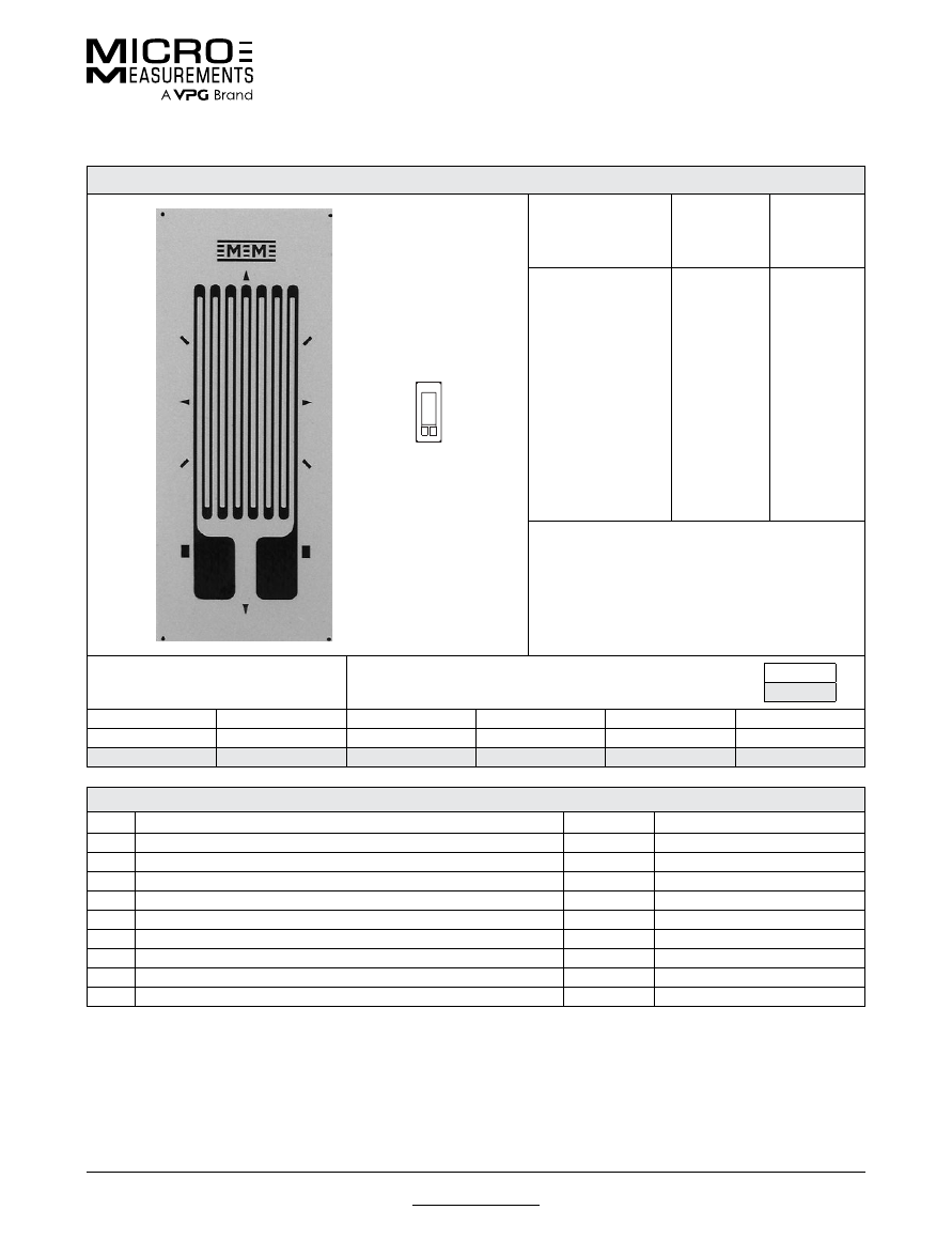
For technical questions, contact
mm@vpgsensors.com
Document No.: 11294
Revision: 08-Jan-2016
www.micro-measurements.com
45
250BG
General Purpose Strain Gages—Linear Pattern
General Purpose Strain Gages—Linear Pattern
GAGE PATTERN DATA
actual size
GAGE
DESIGNATION
See Note 1, 3
RESISTANCE
(OHMS)
See Note 2
OPTIONS
AVAILABLE
See Note 3
EA-XX-250BG-120
ED-DY-250BG-350
WA-XX-250BG-120
WK-XX-250BG-350
EP-XX-250BG-120
SA-XX-250BG-120
SK-XX-250BG-350
SD-DY-250BG-350
WD-DY-250BG-350
120 ± 0.15%
350 ± 0.3%
120 ± 0.3%
350 ± 0.3%
120 ± 0.15%
120 ± 0.3%
350 ± 0.3%
350 ± 0.6%
350 ± 0.6%
W, E, L, LE,
P
E, L*, LE*
W*
W*
DESCRIPTION
Widely used general-purpose gage. Compact
geometry. See also 250UN pattern.
GAGE DIMENSIONS
Legend
ES = Each Section
CP = Complete Pattern
S = Section (S1 = Section 1)
M = Matrix
inch
millimeter
Gage Length
Overall Length
Grid Width
Overall Width
Matrix Length
Matrix Width
0.250
0.375
0.125
0.125
0.52
0.22
6.35
9.53
3.18
3.18
13.2
5.6
GAGE SERIES DATA
—
See Gage Series datasheet for complete specifications
Series
Description
Strain Range
Temperature Range
EA
Constantan foil in combination with a tough, flexible, polyimide backing.
±5%
–100° to +350°F (–75° to +175°C)
ED
Isoelastic foil in combination with tough, flexible polyimide film.
±2%
–320° to +400°F (–195° to +205°C)
WA
Fully encapsulated constantan gages with high-endurance leadwires.
±2%
–100° to +400°F (–75° to +205°)
WK
Fully encapsulated K-alloy gages with high-endurance leadwires.
±1.5%
–452° to +550°F (–269° to +290°C)
EP
Annealed constantan foil with tough, high-elongation polyimide backing.
±20%
–100° to +400°F (–75° to +205°C)
SA
Fully encapsulated constantan gages with solder dots.
±2%
–100° to +400°F (–75° to +205°C)
SK
Fully encapsulated K-alloy gages with solder dots.
±1.5%
–452° to +450°F (–269° to +230°C)
SD
Equivalent to WD Series, but with solder dots instead of leadwires.
±1.5%
–320° to +400°F (–195° to +205°C)
WD
Fully encapsulated isoelastic gages with high-endurance leadwires.
±1.5%
–320° to +500°F (–195° to +260°C)
Note 1:
Insert desired S-T-C number in spaces marked XX.
Note 2:
Tolerance is increased when Option W, E, SE, LE, or P is specified.
Note 3:
Products with designations and options shown in
bold
are not RoHS compliant.
*Options available but not normally recommended. See Optional Features datasheet for details.
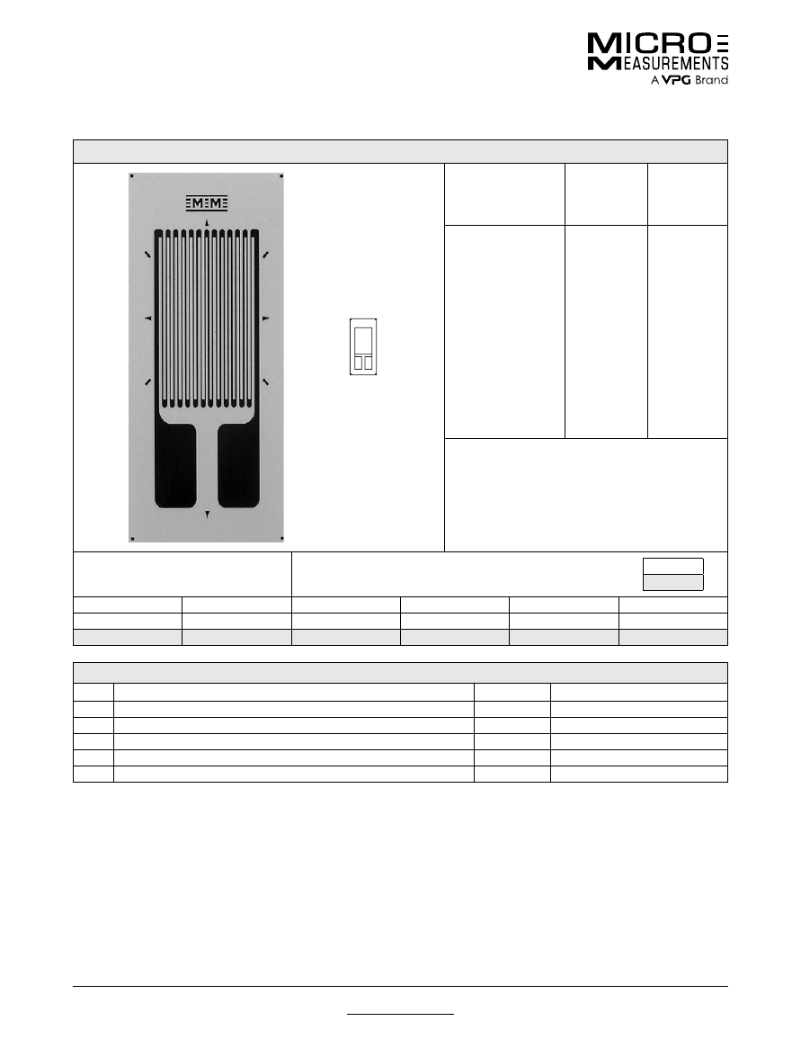
For technical questions, contact
mm@vpgsensors.com
www.micro-measurements.com
46
Document No.: 11295
Revision: 22-Sep-2015
250BK
General Purpose Strain Gages—Linear Pattern
General Purpose Strain Gages—Linear Pattern
GAGE PATTERN DATA
actual size
GAGE
DESIGNATION
See Note 1, 3
RESISTANCE
(OHMS)
See Note 2
OPTIONS
AVAILABLE
See Note 3
EA-XX-250BK-10C
WA-XX-250BK-10C
WK-XX-250BK-30C
SA-XX-250BK-10C
SK-XX-250BK-30C
1000 ± 0.15%
1000 ± 0.3%
3000 ± 0.3%
1000 ± 0.3%
3000 ± 0.3%
W, E, L, LE,
P
W*
W*
DESCRIPTION
High-resistance gage with good power dissipation
capability for high-output applications or use on
plastics.
GAGE DIMENSIONS
Legend
ES = Each Section
CP = Complete Pattern
S = Section (S1 = Section 1)
M = Matrix
inch
millimeter
Gage Length
Overall Length
Grid Width
Overall Width
Matrix Length
Matrix Width
0.250
0.430
0.175
0.175
0.58
0.27
6.35
10.92
4.45
4.45
14.7
6.9
GAGE SERIES DATA
—
See Gage Series datasheet for complete specifications
Series
Description
Strain Range
Temperature Range
EA
Constantan foil in combination with a tough, flexible, polyimide backing.
±5%
–100° to +350°F (–75° to +175°C)
WA
Fully encapsulated constantan gages with high-endurance leadwires.
±2%
–100° to +400°F (–75° to +205°)
WK
Fully encapsulated K-alloy gages with high-endurance leadwires.
±1.5%
–452° to +550°F (–269° to +290°C)
SA
Fully encapsulated constantan gages with solder dots.
±2%
–100° to +400°F (–75° to +205°C)
SK
Fully encapsulated K-alloy gages with solder dots.
±1.5%
–452° to +450°F (–269° to +230°C)
Note 1:
Insert desired S-T-C number in spaces marked XX.
Note 2:
Tolerance is increased when Option W, E, SE, LE, or P is specified.
Note 3:
Products with designations and options shown in
bold
are not RoHS compliant.
*Options available but not normally recommended. See Optional Features datasheet for details.
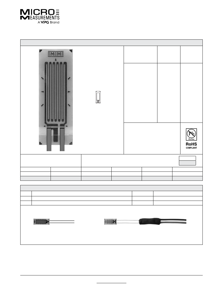
For technical questions, contact
mm@vpgsensors.com
Document No.: 11297
Revision: 22-Sep-2015
www.micro-measurements.com
47
250LW
General Purpose Strain Gages—Linear Pattern
General Purpose Strain Gages—Linear Pattern
GAGE PATTERN DATA
actual size
GAGE
DESIGNATION
See Note 1
RESISTANCE
(OHMS)
OPTIONS
AVAILABLE
L2A-XX-250LW-120
L2A-XX-250LW-350
C2A-XX-250LW-120
C2A-XX-250LW-350
120 ± 0.6%
350 ± 0.6%
120 ± 0.6%
350 ± 0.6%
DESCRIPTION
Widely used general-purpose gage.
GAGE DIMENSIONS
Legend
ES = Each Section
CP = Complete Pattern
S = Section (S1 = Section 1)
M = Matrix
inch
millimeter
Gage Length
Overall Length
Grid Width
Overall Width
Matrix Length
Matrix Width
0.250
0.363
0.100
0.100
0.440
0.170
6.35
9.22
2.54
2.54
11.18
4.32
GAGE SERIES DATA
—
See Gage Series datasheet for complete specifications
Series
Description
Strain Range
Temperature Range
L2A
Encapsulated constantan gages with preattached ribbon leads.
±3%
–100° to +250°F (–75° to +120°C)
C2A
Encapsulated constantan gages with preattached ready-to-use cables.
±3%
–60° to +180°F (–50° to +80°C)
Note 1:
Insert desired S-T-C number in spaces marked XX.
Example of an
L2A Construction
Example of a
C2A Construction
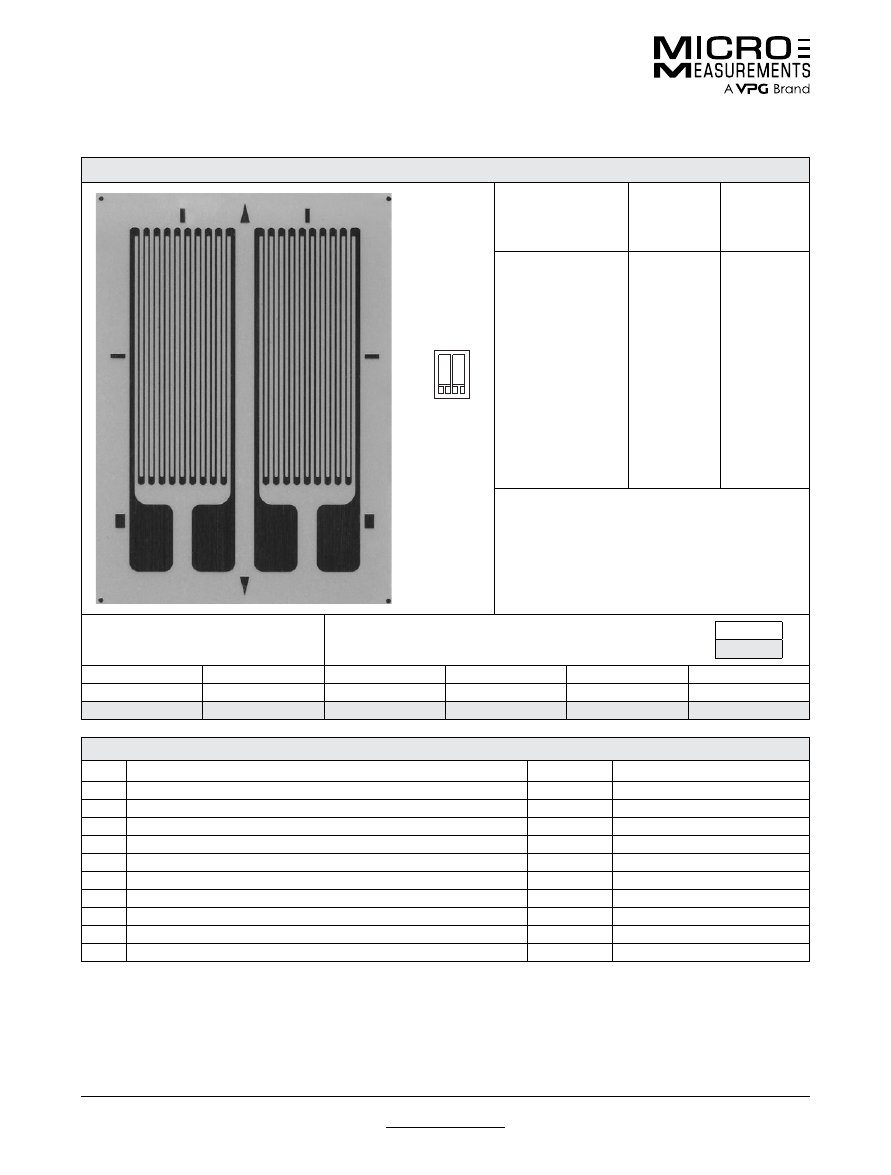
For technical questions, contact
mm@vpgsensors.com
www.micro-measurements.com
48
Document No.: 11333
Revision: 22-Sep-2015
250PD
General Purpose Strain Gages—Linear Pattern
General Purpose Strain Gages—Linear Pattern
GAGE PATTERN DATA
GAGE
DESIGNATION
See Note 1, 3
RESISTANCE
(OHMS)
See Note 2
OPTIONS
AVAILABLE
See Note 3
EA-XX-250PD-120
EA-XX-250PD-350
ED-DY-250PD-350
EK-XX-250PD-10C
S2K-XX-250PD-10C
WA-XX-250PD-120
WA-XX-250PD-350
WK-XX-250PD-350
WK-XX-250PD-10C
SA-XX-250PD-120
SA-XX-250PD-350
SK-XX-250PD-350
SK-XX-250PD-10C
SD-DY-250PD-350
WD-DY-250PD-350
120 ± 0.2%
350 ± 0.2%
350 ± 0.4%
1000 ± 0.2%
1000 ± 0.4%
120 ± 0.3%
350 ± 0.3%
350 ± 0.4%
1000 ± 0.4%
120 ± 0.4%
350 ± 0.4%
350 ± 0.4%
1000 ± 0.4%
350 ± 0.8%
350 ± 0.8%
W, E, L, LE
W, E, L, LE
E
W,
SE
W*
W*
W*
W*
DESCRIPTION
Dual-element pattern with longitudinal grid centerlines
spaced 0.130 in [3.30 mm] apart. See also 250MQ
pattern. EK-Series gages are supplied with duplex
copper pads (DP) when optional feature W or SE is
not specified.
GAGE DIMENSIONS
Legend
ES = Each Section
CP = Complete Pattern
S = Section (S1 = Section 1)
M = Matrix
inch
millimeter
Gage Length
Overall Length
Grid Width
Overall Width
Matrix Length
Matrix Width
0.250
0.358
0.110
0.240
0.44
0.32
6.35
9.09
2.79
6.10
11.2
8.1
GAGE SERIES DATA
—
See Gage Series datasheet for complete specifications
Series
Description
Strain Range
Temperature Range
EA
Constantan foil in combination with a tough, flexible, polyimide backing.
±5%
–100° to +350°F (–75° to +175°C)
ED
Isoelastic foil in combination with tough, flexible polyimide film.
±2%
–320° to +400°F (–195° to +205°C)
EK
K-alloy foil in combination with a tough, flexible polyimide backing.
±1.5%
–320° to +350°F (–195° to +175°C)
S2K
K-alloy foil with laminated thick, high-performance polyimide backing.
±1.5%
–100° to +250°F (–75° to +120°C)
WA
Fully encapsulated constantan gages with high-endurance leadwires.
±2%
–100° to +400°F (–75° to +205°)
WK
Fully encapsulated K-alloy gages with high-endurance leadwires.
±1.5%
–452° to +550°F (–269° to +290°C)
SA
Fully encapsulated constantan gages with solder dots.
±2%
–100° to +400°F (–75° to +205°C)
SK
Fully encapsulated K-alloy gages with solder dots.
±1.5%
–452° to +450°F (–269° to +230°C)
SD
Equivalent to WD Series, but with solder dots instead of leadwires.
±1.5%
–320° to +400°F (–195° to +205°C)
WD
Fully encapsulated isoelastic gages with high-endurance leadwires.
±1.5%
–320° to +500°F (–195° to +260°C)
Note 1:
Insert desired S-T-C number in spaces marked XX.
Note 2:
Tolerance is increased when Option W, E, SE, LE, or P is specified.
Note 3:
Products with designations and options shown in
bold
are not RoHS compliant.
*Options available but not normally recommended. See Optional Features datasheet for details.
actual size
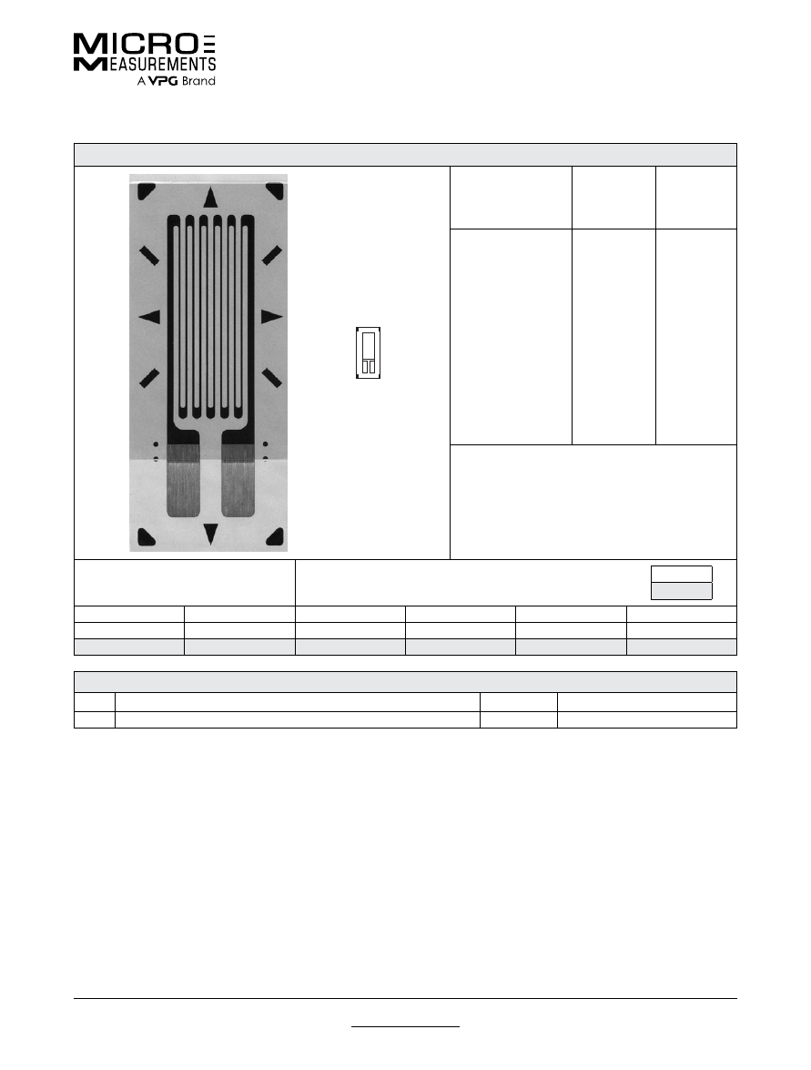
For technical questions, contact
mm@vpgsensors.com
Document No.: 11298
Revision: 25-Aug-2015
www.micro-measurements.com
49
250UN
General Purpose Strain Gages—Linear Pattern
General Purpose Strain Gages—Linear Pattern
GAGE PATTERN DATA
actual size
GAGE
DESIGNATION
See Note 1
RESISTANCE
(OHMS)
OPTIONS
AVAILABLE
See Note 2
CEA-XX-250UN-120
CEA-XX-250UN-350
120 ± 0.3%
350 ± 0.3%
P2
P2
DESCRIPTION
General-purpose gage with narrow geometry. Exposed
solder tab area 0.08 x 0.05 in (2.0 x 1.1 mm). See also
250UW pattern.
GAGE DIMENSIONS
Legend
ES = Each Section
CP = Complete Pattern
S = Section (S1 = Section 1)
M = Matrix
inch
millimeter
Gage Length
Overall Length
Grid Width
Overall Width
Matrix Length
Matrix Width
0.250
0.415
0.120
0.120
0.52
0.22
6.35
10.54
3.05
3.05
13.2
5.6
GAGE SERIES DATA
—
See Gage Series datasheet for complete specifications
Series
Description
Strain Range
Temperature Range
CEA
Universal general-purpose strain gages.
±5%
–100° to +350°F (–75° to +175°C)
Note 1:
Insert desired S-T-C number in spaces marked XX.
Note 2:
Products with designations and options shown in
bold
are not RoHS compliant.
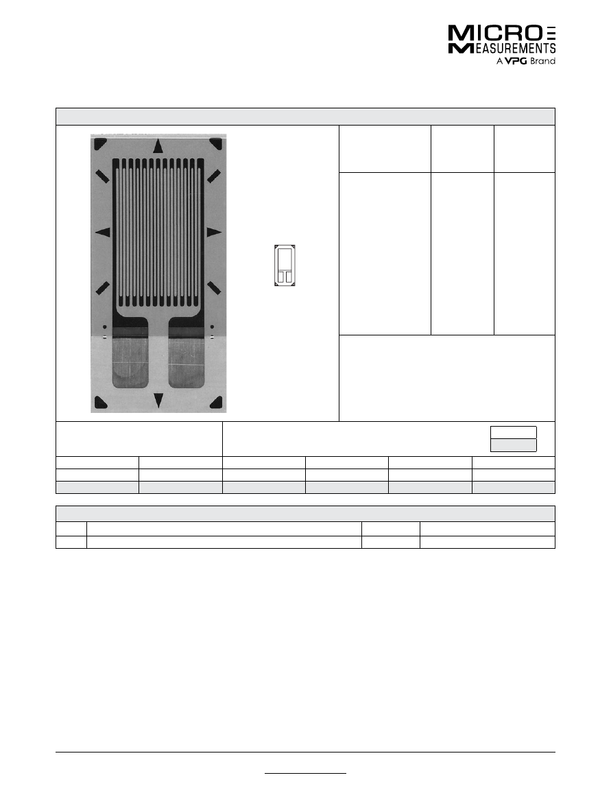
For technical questions, contact
mm@vpgsensors.com
www.micro-measurements.com
50
Document No.: 11312
Revision: 25-Aug-2015
250UW
General Purpose Strain Gages—Linear Pattern
General Purpose Strain Gages—Linear Pattern
GAGE PATTERN DATA
actual size
GAGE
DESIGNATION
See Note 1
RESISTANCE
(OHMS)
OPTIONS
AVAILABLE
See Note 2
CEA-XX-250UW-120
CEA-XX-250UW-175
CEA-XX-250UW-350
CEA-XX-250UW-10C
120 ± 0.3%
175 ± 0.3%
350 ± 0.3%
1000 ± 0.3%
P2
P2
P2
P2
DESCRIPTION
General-purpose gage. Exposed solder tab area
0.10 x 0.07 in (2.5 x 1.8 mm). See also 250UN pattern.
GAGE DIMENSIONS
Legend
ES = Each Section
CP = Complete Pattern
S = Section (S1 = Section 1)
M = Matrix
inch
millimeter
Gage Length
Overall Length
Grid Width
Overall Width
Matrix Length
Matrix Width
0.250
0.450
0.180
0.180
0.55
0.27
6.35
11.43
4.57
4.57
14.0
6.9
GAGE SERIES DATA
—
See Gage Series datasheet for complete specifications
Series
Description
Strain Range
Temperature Range
CEA
Universal general-purpose strain gages.
±5%
–100° to +350°F (–75° to +175°C)
Note 1:
Insert desired S-T-C number in spaces marked XX.
Note 2:
Products with designations and options shown in
bold
are not RoHS compliant.
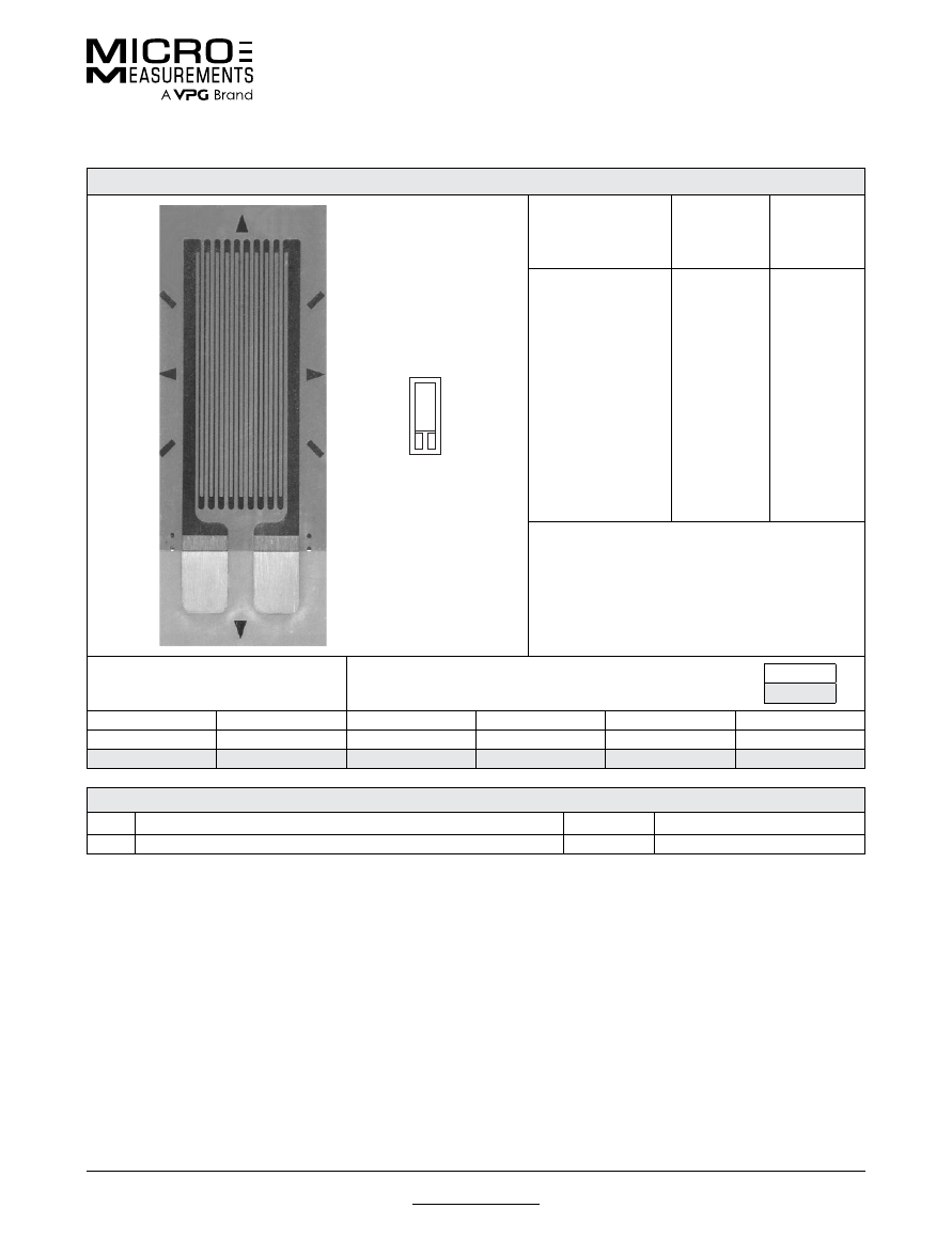
For technical questions, contact
mm@vpgsensors.com
Document No.: 11335
Revision: 22-Sep-2015
www.micro-measurements.com
51
375UW
General Purpose Strain Gages—Linear Pattern
General Purpose Strain Gages—Linear Pattern
GAGE PATTERN DATA
actual size
GAGE
DESIGNATION
See Note 1
RESISTANCE
(OHMS)
OPTIONS
AVAILABLE
See Note 2
CEA-XX-375UW-120
CEA-XX-375UW-350
120 ± 0.3%
350 ± 0.3%
P2
P2
DESCRIPTION
General-purpose gage. Exposed solder tab area
0.10 x 0.07 in (2.5 x 1.8 mm).
GAGE DIMENSIONS
Legend
ES = Each Section
CP = Complete Pattern
S = Section (S1 = Section 1)
M = Matrix
inch
millimeter
Gage Length
Overall Length
Grid Width
Overall Width
Matrix Length
Matrix Width
0.375
0.575
0.180
0.180
0.67
0.27
9.53
14.61
4.57
4.57
17.0
6.9
GAGE SERIES DATA
—
See Gage Series datasheet for complete specifications
Series
Description
Strain Range
Temperature Range
CEA
Universal general-purpose strain gages.
±5%
–100° to +350°F (–75° to +175°C)
Note 1:
Insert desired S-T-C number in spaces marked XX.
Note 2:
Products with designations and options shown in
bold
are not RoHS compliant.
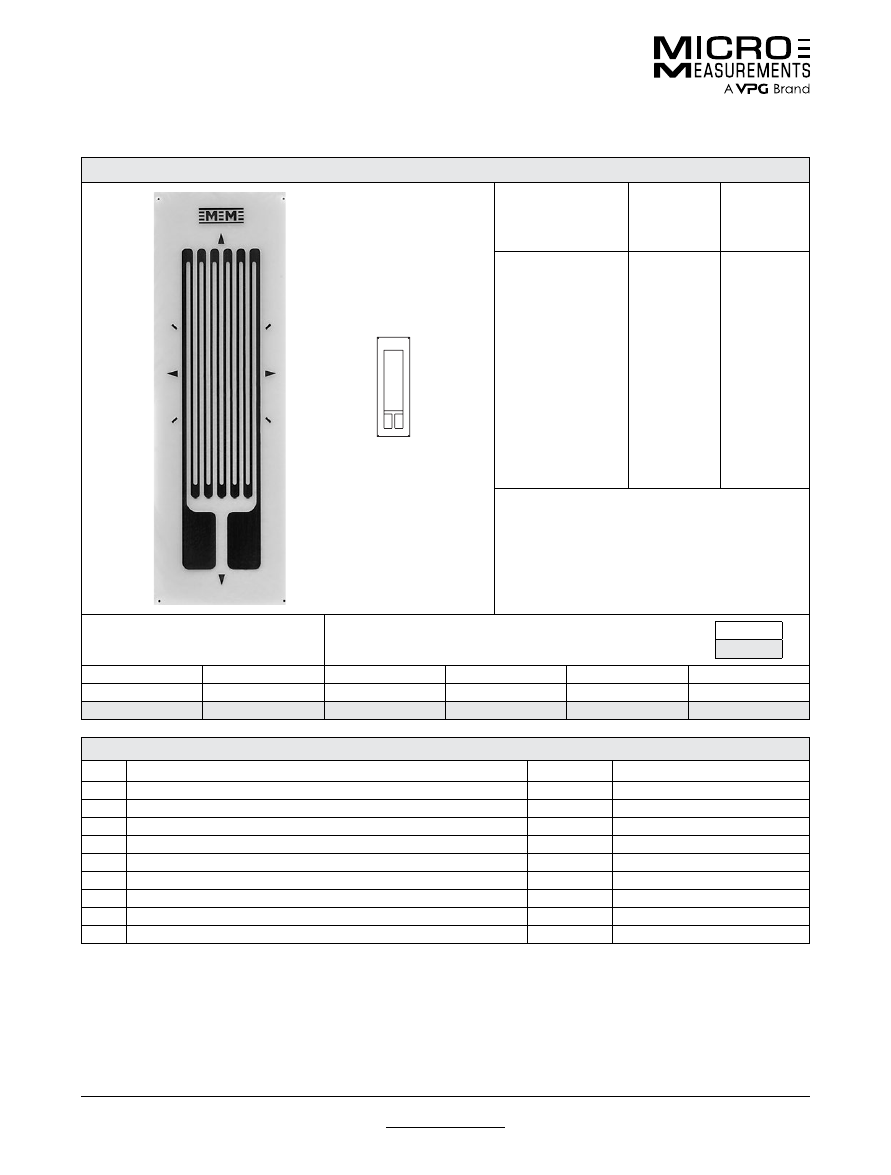
For technical questions, contact
mm@vpgsensors.com
www.micro-measurements.com
52
Document No.: 11305
Revision: 22-Sep-2015
500BH
General Purpose Strain Gages—Linear Pattern
General Purpose Strain Gages—Linear Pattern
GAGE PATTERN DATA
actual size
GAGE
DESIGNATION
See Note 1, 3
RESISTANCE
(OHMS)
See Note 2
OPTIONS
AVAILABLE
See Note 3
EA-XX-500BH-120
ED-DY-500BH-350
WA-XX-500BH-120
WK-XX-500BH-350
EP-08-500BH-120
SA-XX-500BH-120
SK-XX-500BH-350
SD-DY-500BH-350
WD-DY-500BH-350
120 ± 0.15%
350 ± 0.3%
120 ± 0.3%
350 ± 0.3%
120 ± 0.15%
120 ± 0.3%
350 ± 0.3%
350 ± 0.6%
350 ± 0.6%
W, E, L, LE,
P
E, L*, LE*
W*
W*
DESCRIPTION
Widely used general-purpose gage with compact
geometry. See also 500BL and 500UW patterns.
GAGE DIMENSIONS
Legend
ES = Each Section
CP = Complete Pattern
S = Section (S1 = Section 1)
M = Matrix
inch
millimeter
Gage Length
Overall Length
Grid Width
Overall Width
Matrix Length
Matrix Width
0.500
0.720
0.175
0.175
0.92
0.30
12.70
18.29
4.45
4.45
23.4
7.6
GAGE SERIES DATA
—
See Gage Series datasheet for complete specifications
Series
Description
Strain Range
Temperature Range
EA
Constantan foil in combination with a tough, flexible, polyimide backing.
±5%
–100° to +350°F (–75° to +175°C)
ED
Isoelastic foil in combination with tough, flexible polyimide film.
±2%
–320° to +400°F (–195° to +205°C)
WA
Fully encapsulated constantan gages with high-endurance leadwires.
±2%
–100° to +400°F (–75° to +205°)
WK
Fully encapsulated K-alloy gages with high-endurance leadwires.
±1.5%
–452° to +550°F (–269° to +290°C)
EP
Annealed constantan foil with tough, high-elongation polyimide backing.
±20%
–100° to +400°F (–75° to +205°C)
SA
Fully encapsulated constantan gages with solder dots.
±2%
–100° to +400°F (–75° to +205°C)
SK
Fully encapsulated K-alloy gages with solder dots.
±1.5%
–452° to +450°F (–269° to +230°C)
SD
Equivalent to WD Series, but with solder dots instead of leadwires.
±1.5%
–320° to +400°F (–195° to +205°C)
WD
Fully encapsulated isoelastic gages with high-endurance leadwires.
±1.5%
–320° to +500°F (–195° to +260°C)
Note 1:
Insert desired S-T-C number in spaces marked XX.
Note 2:
Tolerance is increased when Option W, E, SE, LE, or P is specified.
Note 3:
Products with designations and options shown in
bold
are not RoHS compliant.
*Options available but not normally recommended. See Optional Features datasheet for details.
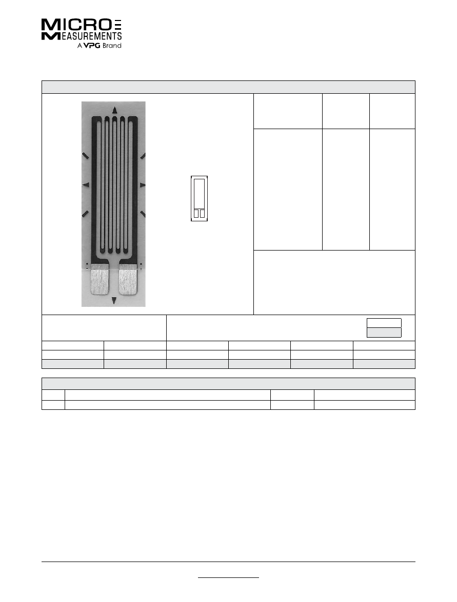
For technical questions, contact
mm@vpgsensors.com
Document No.: 11307
Revision: 25-Aug-2015
www.micro-measurements.com
53
500UW
General Purpose Strain Gages—Linear Pattern
General Purpose Strain Gages—Linear Pattern
GAGE PATTERN DATA
actual size
GAGE
DESIGNATION
See Note 1
RESISTANCE
(OHMS)
OPTIONS
AVAILABLE
See Note 2
CEA-XX-500UW-120
CEA-XX-500UW-350
120 ± 0.3%
350 ± 0.3%
P2
P2
DESCRIPTION
General-purpose gage. Exposed solder tab area
0.10 x 0.07 in (2.5 x 1.8 mm).
GAGE DIMENSIONS
Legend
ES = Each Section
CP = Complete Pattern
S = Section (S1 = Section 1)
M = Matrix
inch
millimeter
Gage Length
Overall Length
Grid Width
Overall Width
Matrix Length
Matrix Width
0.500
0.700
0.180
0.180
0.80
0.27
12.70
17.78
4.57
4.57
20.3
6.9
GAGE SERIES DATA
—
See Gage Series datasheet for complete specifications
Series
Description
Strain Range
Temperature Range
CEA
Universal general-purpose strain gages.
±5%
–100° to +350°F (–75° to +175°C)
Note 1:
Insert desired S-T-C number in spaces marked XX.
Note 2:
Tolerance is increased when Option W, E, SE, LE, or P is specified.
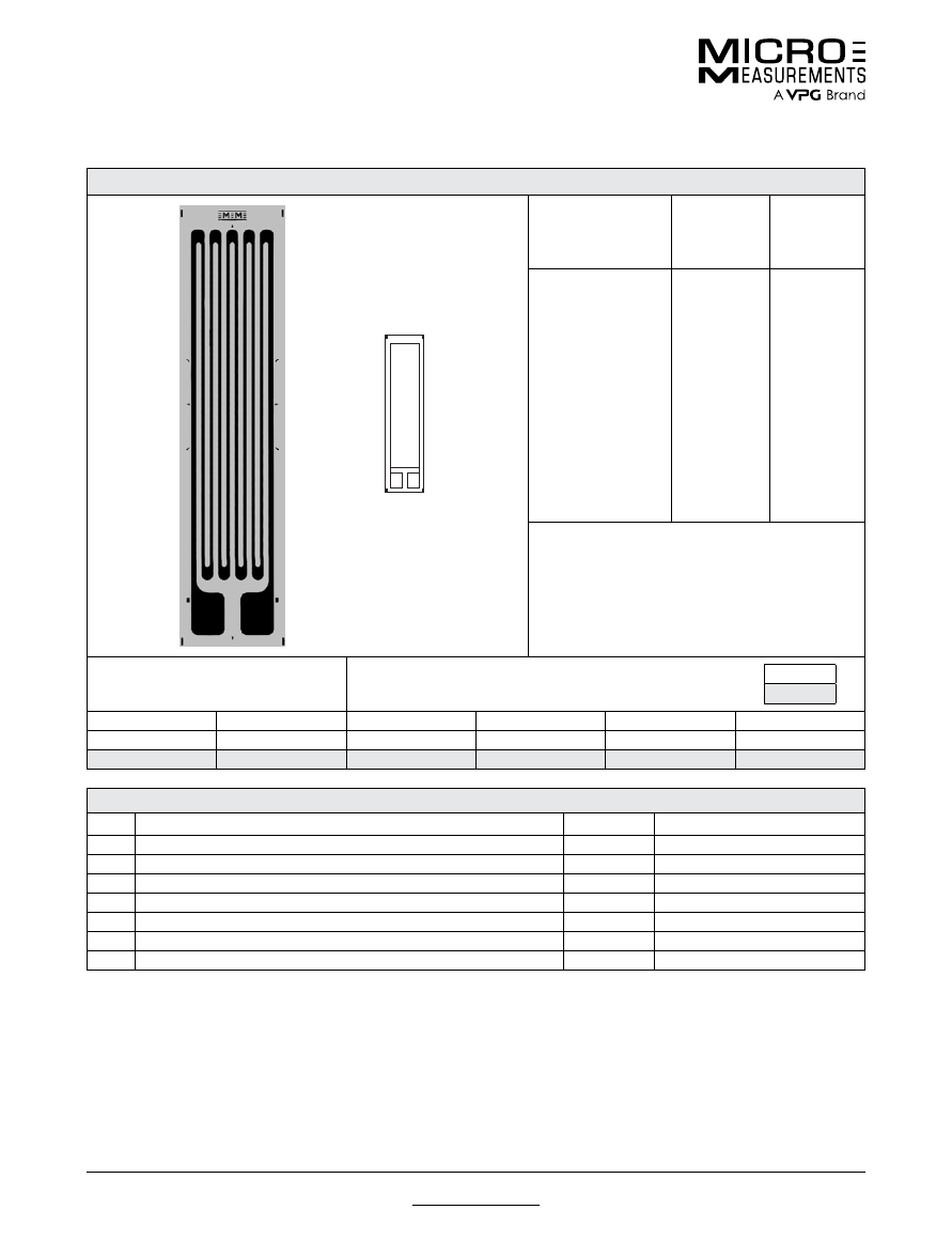
For technical questions, contact
mm@vpgsensors.com
www.micro-measurements.com
54
Document No.: 11315
Revision: 22-Sep-2015
10CBE
General Purpose Strain Gages—Linear Pattern
General Purpose Strain Gages—Linear Pattern
GAGE PATTERN DATA
actual size
GAGE
DESIGNATION
See Note 1, 3
RESISTANCE
(OHMS)
See Note 2
OPTIONS
AVAILABLE
See Note 3
N2A-XX-10CBE-120
N2A-XX-10CBE-350
EA-XX-10CBE-120
WA-XX-10CBE-120
WK-XX-10CBE-350
EP-XX-10CBE-120
SA-XX-10CBE-120
SK-XX-10CBE-350
120 ± 0.15%
350 ± 0.15%
120 ± 0.15%
120 ± 0.3%
350 ± 0.3%
120 ± 0.15%
120 ± 0.3%
350 ± 0.3%
W, E, L, LE,
P
W, E, L, LE,
P
W, E, L, LE,
P
W*
W*
DESCRIPTION
Large general-purpose gage.
GAGE DIMENSIONS
Legend
ES = Each Section
CP = Complete Pattern
S = Section (S1 = Section 1)
M = Matrix
inch
millimeter
Gage Length
Overall Length
Grid Width
Overall Width
Matrix Length
Matrix Width
1.000
1.250
0.250
0.250
1.36
0.33
25.40
31.75
6.35
6.35
34.5
8.4
GAGE SERIES DATA
—
See Gage Series datasheet for complete specifications
Series
Description
Strain Range
Temperature Range
N2A
Constantan foil gages with a thin, laminated, polyimide-film backing.
±3%
–100° to +200°F (–75° to +95°C)
EA
Constantan foil in combination with a tough, flexible, polyimide backing.
±5%
–100° to +350°F (–75° to +175°C)
WA
Fully encapsulated constantan gages with high-endurance leadwires.
±2%
–100° to +400°F (–75° to +205°)
WK
Fully encapsulated K-alloy gages with high-endurance leadwires.
±1.5%
–452° to +550°F (–269° to +290°C)
EP
Annealed constantan foil with tough, high-elongation polyimide backing.
±20%
–100° to +400°F (–75° to +205°C)
SA
Fully encapsulated constantan gages with solder dots.
±2%
–100° to +400°F (–75° to +205°C)
SK
Fully encapsulated K-alloy gages with solder dots.
±1.5%
–452° to +450°F (–269° to +230°C)
Note 1:
Insert desired S-T-C number in spaces marked XX.
Note 2:
Tolerance is increased when Option W, E, SE, LE, or P is specified.
Note 3:
Products with designations and options shown in
bold
are not RoHS compliant.
*Options available but not normally recommended. See Optional Features datasheet for details.
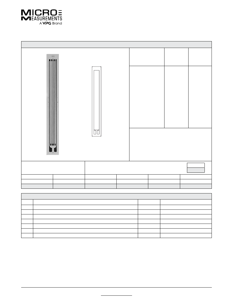
For technical questions, contact
mm@vpgsensors.com
Document No.: 11291
Revision: 22-Sep-2015
www.micro-measurements.com
55
20CBW
General Purpose Strain Gages—Linear Pattern
General Purpose Strain Gages—Linear Pattern
GAGE PATTERN DATA
actual size
GAGE
DESIGNATION
See Note 1, 3
RESISTANCE
(OHMS)
See Note 2
OPTIONS
AVAILABLE
See Note 3
N2A-XX-20CBW-120
N2A-XX-20CBW-350
EA-XX-20CBW-120
WA-XX-20CBW-120
WK-XX-20CBW-350
EP-XX-20CBW-120
SA-XX-20CBW-120
SK-XX-20CBW-350
120 ± 0.2%
350 ± 0.2%
120 ± 0.2%
350 ± 0.4%
120 ± 0.4%
350 ± 0.2%
120 ± 0.4%
350 ± 0.4%
W, E, L, LE,
P
W, E, L, LE,
P
W, E, L, LE,
P
W*
W*
DESCRIPTION
For use on concrete and for strain integration on large
specimens.
GAGE DIMENSIONS
Legend
ES = Each Section
CP = Complete Pattern
S = Section (S1 = Section 1)
M = Matrix
inch
millimeter
Gage Length
Overall Length
Grid Width
Overall Width
Matrix Length
Matrix Width
2.000
2.250
0.188
0.188
2.46
0.32
50.80
57.15
4.78
4.78
62.5
8.1
GAGE SERIES DATA
—
See Gage Series datasheet for complete specifications
Series
Description
Strain Range
Temperature Range
N2A
Constantan foil gages with a thin, laminated, polyimide-film backing.
±3%
–100° to +200°F (–75° to +95°C)
EA
Constantan foil in combination with a tough, flexible, polyimide backing.
±5%
–100° to +350°F (–75° to +175°C)
WA
Fully encapsulated constantan gages with high-endurance leadwires.
±2%
–100° to +400°F (–75° to +205°)
WK
Fully encapsulated K-alloy gages with high-endurance leadwires.
±1.5%
–452° to +550°F (–269° to +290°C)
EP
Annealed constantan foil with tough, high-elongation polyimide backing.
±20%
–100° to +400°F (–75° to +205°C)
SA
Fully encapsulated constantan gages with solder dots.
±2%
–100° to +400°F (–75° to +205°C)
SK
Fully encapsulated K-alloy gages with solder dots.
±1.5%
–452° to +450°F (–269° to +230°C)
Note 1:
Insert desired S-T-C number in spaces marked XX.
Note 2:
Tolerance is increased when Option W, E, SE, LE, or P is specified.
Note 3:
Products with designations and options shown in
bold
are not RoHS compliant.
*Options available but not normally recommended. See Optional Features datasheet for details.
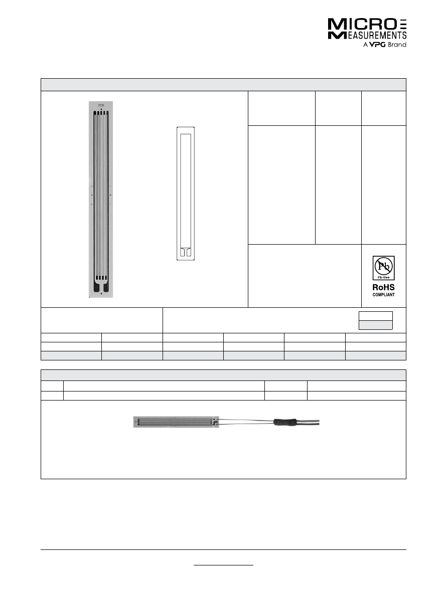
For technical questions, contact
mm@vpgsensors.com
www.micro-measurements.com
56
Document No.: 11256
Revision: 26-Oct-2015
20CLW
General Purpose Strain Gages—Linear Pattern
General Purpose Strain Gages—Linear Pattern
GAGE PATTERN DATA
actual size
GAGE
DESIGNATION
See Note 1
RESISTANCE
(OHMS)
OPTIONS
AVAILABLE
C2A-XX-20CLW-120
C2A-XX-20CLW-350
120 ± 0.6%
350 ± 0.6%
DESCRIPTION
For use on concrete and for strain
integration on large specimens.
GAGE DIMENSIONS
Legend
ES = Each Section
CP = Complete Pattern
S = Section (S1 = Section 1)
M = Matrix
inch
millimeter
Gage Length
Overall Length
Grid Width
Overall Width
Matrix Length
Matrix Width
2.000
2.155
0.175
0.175
2.232
0.235
50.80
54.740
4.450
4.450
56.692
5.969
GAGE SERIES DATA
—
See Gage Series datasheet for complete specifications
Series
Description
Strain Range
Temperature Range
C2A
Encapsulated constantan gages with preattached ready-to-use cables.
±3%
–60° to +180°F (–50° to +80°C)
Example of a
C2A Construction
Note 1:
Insert desired S-T-C number in spaces marked XX.
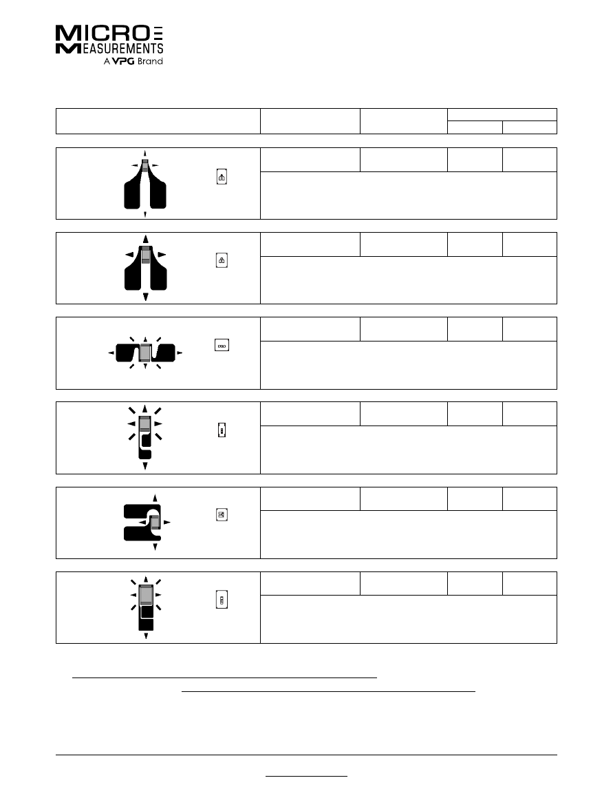
For technical questions, contact
mm@vpgsensors.com
Document No.: 11321
Revision: 05-Jan-2016
www.micro-measurements.com
57
Other Linear Patterns
General Purpose Strain Gages
General Purpose Strain Gages
GAGE PATTERN
GAGE SERIES
See Note 1
GAGE RESISTANCE
(OHMS)
GAGE LENGTH
inches
millimeters
008CL
actual size
SA
120
0.008
0.2
Micro-grid gage for strain measurement in high-gradient areas.
Matrix size: 0.20L x 0.13W in. (5.1L x 3.3W mm)
015CK
actual size
EA,
WA
, EP,
SA
120
0.015
0.38
Micro-miniature pattern with enlarged solder tabs. See also 015UW pattern.
Matrix size: 0.19L x 0.15W in. (4.8L x 3.8W mm)
015EH
actual size
EA, EP,
SA, SK
120
0.015
0.38
Micro-miniature pattern with tab at each side of grid.
Matrix size: 0.15L x 0.19W in. (3.8L x 4.8W mm)
015LA
actual size
EA, EP
120
0.015
0.38
Primarily used in small radii where gage tabs must be at one end.
Matrix size: 0.18L x 0.10W in. (4.6L x 2.5W mm)
015SE
actual size
EA, EP,
SA
120
0.015
0.38
Micro-miniature pattern with tabs on one side for use near abutments.
Matrix size: 0.16L x 0.14W in. (4.1L x 3.6W mm)
030LB
actual size
EA, EP,
SA
120
0.03
0.76
Miniature gage pattern for small radii where gage tabs must be at one end.
Matrix size: 0.24L x 0.15W in. (6.1L x 3.8W mm)
Note 1:
Products with designations and options shown in
bold
are not RoHS compliant.
See www.micro-measurements.com/stress-analysis-strain-gages/other-linear-patterns/
for complete specifications of patterns listed.
For all linear patterns offered, see www.micro-measurements.com/stress-analysis-strain-gages/all-linear-patterns/
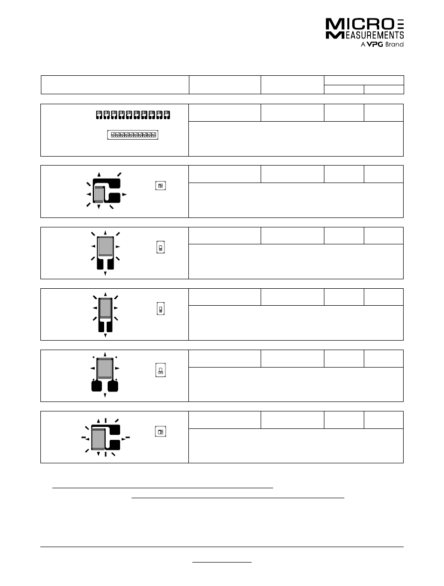
For technical questions, contact
mm@vpgsensors.com
www.micro-measurements.com
58
Document No.: 11321
Revision: 05-Jan-2016
Other Linear Patterns
General Purpose Strain Gages
GAGE PATTERN
GAGE SERIES
See Note 1
GAGE RESISTANCE
(OHMS)
GAGE LENGTH
inches
millimeters
031MF
EA,
SA
120
0.031
0.79
Miniature ten-element strip gage with electrically independent grids. All grids
parallel to long axis of pattern. Grid centerline spacing 0.080 in (2.03 mm).
Matrix size: 0.94L x 0.19W in. (23.9L x 4.8W mm)
actual size
032SG
actual size
EA,
WA
, WK, EP,
SA, SK
120
0.032
0.81
Miniature gage with side-tab geometry.
Matrix size: 0.16L x 0.19W in. (4.1L x 4.8W mm)
045AL
actual size
EA,
SA
350
0.045
1.14
Miniature high-resistance gage.
Matrix size: 0.22L x 0.14W in. (5.6L x 3.6W mm)
050AH
actual size
EA, ED, EP,
SA, SK, SD
120, 350
0.05
1.27
General-purpose miniature gage.
Matrix size: 0.23L x 0.14W in. (5.8L x 3.6W mm)
050AR
actual size
EA, ED,
WA
, WK,
SA,
SK, SD
, WD
120, 350
0.05
1.27
General-purpose miniature gage with large solder tabs.
Matrix size: 0.25L x 0.18W in. (6.4L x 4.6W mm)
050SB
actual size
EA, ED,
WA
, WK, EP,
SA, SK, SD
, WD
120, 350
0.05
1.27
Similar to the 050AH pattern but with solder tabs at side of grid.
Matrix size: 0.19L x 0.19W in. (4.8L x 4.8W mm)
Note 1:
Products with designations and options shown in
bold
are not RoHS compliant.
See www.micro-measurements.com/stress-analysis-strain-gages/other-linear-patterns/
for complete specifications of patterns listed.
For all linear patterns offered, see www.micro-measurements.com/stress-analysis-strain-gages/all-linear-patterns/
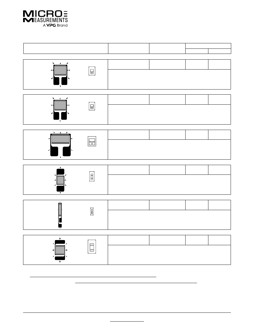
For technical questions, contact
mm@vpgsensors.com
Document No.: 11321
Revision: 05-Jan-2016
www.micro-measurements.com
59
Other Linear Patterns
General Purpose Strain Gages
GAGE PATTERN
GAGE SERIES
See Note 1
GAGE RESISTANCE
(OHMS)
GAGE LENGTH
inches
millimeters
060CD
actual size
EA, ED,
WA
, WK,
SA,
SK, SD
, WD
350, 1000
0.06
1.52
Small high-resistance gage. See also 060CN pattern.
Matrix size: 0.28L x 0.20W in. (7.1L x 5.1W mm)
060CN
actual size
EA, ED,
WA
, WK, EP,
SA, SD
, WD
120, 350
0.06
1.52
Similar to 060CD pattern except for grid resistance.
Matrix size: 0.26L x 0.18W in. (6.6L x 4.6W mm)
060CP
actual size
EA, ED,
WA
, WK, EP,
SA, SK, SD
, WD
120, 350
0.06
1.52
Small high-resistance gage with high power-handling capability.
Matrix size: 0.31L x 0.26W in. (7.9L x 6.6W mm)
062DF
actual size
EA, ED,
WA
, WK, EP,
SA, SK, SD
, WD
120, 350
0.062
1.57
General-purpose gage with solder tab at each end of grid. See also 062DN
pattern.
Matrix size: 0.32L x 0.16W in. (8.1L x 4.1W mm)
070LC
actual size
EA
120, 350
0.07
1.78
Very narrow gage for use in restricted areas.
Matrix size: 0.24L x 0.09W in. (6.1L x 2.3W mm)
090DG
actual size
EA, ED, EP,
SA, SK, SD
120, 350
0.09
2.29
Intermediate-size grid with tab at each end. See also 090DH and 090EF
patterns.
Matrix size: 0.44L x 0.263W in. (11.2L x 6.6W mm)
Note 1:
Products with designations and options shown in
bold
are not RoHS compliant.
See www.micro-measurements.com/stress-analysis-strain-gages/other-linear-patterns/
for complete specifications of patterns listed.
For all linear patterns offered, see www.micro-measurements.com/stress-analysis-strain-gages/all-linear-patterns/
For technical questions, contact
mm@vpgsensors.com
www.micro-measurements.com
60
Document No.: 11321
Revision: 05-Jan-2016
Other Linear Patterns
General Purpose Strain Gages
090DH
actual size
EA, ED, EP,
SA, SK, SD
350, 1000
0.09
2.29
High-resistance version of the 090DG pattern.
Matrix size: 0.45L x 0.27W in. (11.4L x 6.9W mm)
090EF
actual size
EA, ED, EP,
SA, SK, SD
120, 350
0.09
2.29
Similar to 090DG pattern but with solder tab at each side of grid. See also
090EG pattern.
Matrix size: 0.29L x 0.36W in. (7.4L x 9.1W mm)
090EG
actual size
EA, ED, EP,
SA, SK, SD
350, 1000
0.09
2.29
High-resistance version of the 090EF pattern.
Matrix size: 0.29L x 0.36W in. (7.4L x 9.1W mm)
125BS
actual size
ED, WK,
SK, SD,
WD
120
0.125
3.18
Narrow pattern primarily used in the WK and SK Series for 120-ohm resistance.
Matrix size: 0.38L x 0.14W in. (9.7L x 3.6W mm)
125EP
actual size
EA, ED, EP,
SA, SK, SD
350, 1000
0.125
3.18
High-resistance gage with tab at each side of grid. See also 125EQ pattern.
Matrix size: 0.28L x 0.35W in. (7.1L x 8.9W mm)
125EQ
actual size
EA, ED, EP,
SA, SK, SD
120, 350
0.125
3.18
Similar to 125EP pattern except for grid resistance.
Matrix size: 0.28L x 0.35W in. (7.1L x 8.9W mm)
Note 1:
Products with designations and options shown in
bold
are not RoHS compliant.
See www.micro-measurements.com/stress-analysis-strain-gages/other-linear-patterns/
for complete specifications of patterns listed.
For all linear patterns offered, see www.micro-measurements.com/stress-analysis-strain-gages/all-linear-patterns/
GAGE PATTERN
GAGE SERIES
See Note 1
GAGE RESISTANCE
(OHMS)
GAGE LENGTH
inches
millimeters
For technical questions, contact
mm@vpgsensors.com
Document No.: 11321
Revision: 05-Jan-2016
www.micro-measurements.com
61
Other Linear Patterns
General Purpose Strain Gages
125MG
actual size
EA,
WA
, WK,
SA, SK
120, 350
0.125
3.18
Dual-pattern gage for use in back-to-back bending applications. Longitudinal
grid centerlines spaced 0.250 in (6.35 mm) apart.
Matrix size: 0.32L x 0.47W in. (8.1L x 11.9W mm)
125UE
actual size
CEA
120, 350
0.125
3.18
General-purpose gage with large tab at each end of grid. Exposed solder tab
area 0.08 x 0.07 in (2.0 x 1.8 mm).
Matrix size: 0.57L x 0.20W in. (14.5L x 5.1W mm)
230DS
actual size
EA, ED,
WA
, WK,
EP,
SA, SK, SD,
WD
120, 350
0.23
5.84
General-purpose gage with very narrow geometry.
Matrix size: 0.50L x 0.12W in. (12.7L x 3.0W mm)
250AF
actual size
EA, ED,
WA
, WK, EP,
SA
,
SK, SD
, WD
120, 350
0.25
6.35
General-purpose gage with high-dissipation grid.
Matrix size: 0.57L x 0.36W in. (14.5L x 9.1W mm)
250BB
actual size
EA, ED, EP
120, 350
0.25
6.35
General-purpose gage with large solder tabs.
Matrix size: 0.64L x 0.21W in. (16.3L x 6.9W mm)
250BK
actual size
EA,
WA
, WK,
SA, SK
1000, 3000
0.25
6.35
High-resistance gage with good power dissipation capability for high output
applications or use on plastics.
Matrix size: 0.58L x 0.27W in. (14.7L x 6.9W mm)
Note 1:
Products with designations and options shown in
bold
are not RoHS compliant.
See www.micro-measurements.com/stress-analysis-strain-gages/other-linear-patterns/
for complete specifications of patterns listed.
For all linear patterns offered, see www.micro-measurements.com/stress-analysis-strain-gages/all-linear-patterns/
GAGE PATTERN
GAGE SERIES
See Note 1
GAGE RESISTANCE
(OHMS)
GAGE LENGTH
inches
millimeters
For technical questions, contact
mm@vpgsensors.com
www.micro-measurements.com
62
Document No.: 11321
Revision: 05-Jan-2016
Other Linear Patterns
General Purpose Strain Gages
250BM
actual size
EA, ED,
WA
, WK, EP,
SA
,
SK, SD
, WD
500, 1500
0.25
6.35
General-purpose gage with high-resistance grid.
Matrix size: 0.58L x 0.27W in. (14.7L x 6.9W mm)
250BP
actual size
SK
, WK, ED,
SD
, WD
120
0.25
6.35
A general-purpose gage used primarily to obtain 120-ohm grid resistance in
SK and WK Series.
Matrix size: 0.53L x 0.22W in. (13.5L x 5.6W mm)
250MQ
actual size
EA, ED, EK,
WA
, WK,
SA
,
SK, SD
, WD
350, 1000
0.25
6.35
Dual pattern for back-to-back bending applications. Longitudinal grid
centerlines are spaced 0.185 in (4.70 mm) apart. EK-Series gages are supplied
with duplex copper pads (DP) when optional feature W or SE is not specified.
Matrix size: 0.47L x 0.40W in. (11.9L x 10.2W mm)
350DD
actual size
EA, ED,
WA
, WK, EP,
SA
,
SK, SD
, WD
350, 1000
0.35
8.89
General-purpose gage with narrow pattern geometry and tab at each end of
grid.
Matrix size: 0.61L x 0.18W in. (15.5L x 4.6W mm)
375BG
actual size
EA, ED,
WA
, WK, EP,
SA
,
SK, SD
, WD
120, 350
0.375
9.53
General-purpose gage.
Matrix size: 0.71L x 0.29W in. (18.0L x 7.4W mm)
500BL
actual size
EA, ED,
WA
, WK, EP,
SA
,
SK, SD
, WD
350, 1000
0.5
12.7
Widely used general-purpose gage with compact geometry.
Matrix size: 0.87L x 0.27W in. (22.1L x 6.9W mm)
Note 1:
Products with designations and options shown in
bold
are not RoHS compliant.
See www.micro-measurements.com/stress-analysis-strain-gages/other-linear-patterns/
for complete specifications of patterns listed.
For all linear patterns offered, see www.micro-measurements.com/stress-analysis-strain-gages/all-linear-patterns/
GAGE PATTERN
GAGE SERIES
See Note 1
GAGE RESISTANCE
(OHMS)
GAGE LENGTH
inches
millimeters
For technical questions, contact
mm@vpgsensors.com
Document No.: 11321
Revision: 05-Jan-2016
www.micro-measurements.com
63
Other Linear Patterns
General Purpose Strain Gages
500GB
EA, ED,
WA
, WK, EP,
SA
,
SK, SD
, WD
120, 350
0.5
12.7
General-purpose gage with very narrow geometry. See also 500GC pattern.
Matrix size: 0.75L x 0.15W in. (19.1L x 3.8W mm)
actual size
500GC
EA, ED,
WA
, WK, EP,
SA
,
SK, SD
, WD
350, 1000
0.5
12.7
General-purpose gage with very narrow geometry.
Matrix size: 0.78L x 0.15W in. (19.8L x 3.8W mm)
actual size
40CBY
N2A, EA,
WA
, WK, EP,
SA, SK
120, 350
4
101.6
For use on concrete and for strain integration on large specimens.
Matrix size: 4.49L x 0.33W in. (114.0L x 8.4W mm)
30% of actual size
Note 1:
Products with designations and options shown in
bold
are not RoHS compliant.
See www.vishaypg.com/micro-measurements/stress-analysis-strain-gages/other-linear-patterns/
for complete specifications.
For all linear patterns offered, see www.micro-measurements.com/stress-analysis-strain-gages/all-linear-patterns/
GAGE PATTERN
GAGE SERIES
See Note 1
GAGE RESISTANCE
(OHMS)
GAGE LENGTH
inches
millimeters

For technical questions, contact
mm@vpgsensors.com
www.micro-measurements.com
64

For technical questions, contact
mm@vpgsensors.com
www.micro-measurements.com
65
Tee Rosettes
(General-Use)
FEATURES
• Gage patterns designed for measuring orthogonal strains
• All patterns have two grids oriented at 0° and 90° angles
• Both stacked and planar constructions available
• Gage lengths from 0.050” (1.27 mm) to 0.250” (6.35 mm)
PATTERNS
050TG .................................................. 66
062LT ................................................... 67
062TJ ................................................... 68
062TT ................................................... 69
062TZ ................................................... 70
062UT ................................................... 71
062WT .................................................. 72
120WT .................................................. 73
125LT ................................................... 74
125TG .................................................. 75
125TM .................................................. 76
125UT ................................................... 77
125WT .................................................. 78
250TM ................................................... 79
250UT ................................................... 80
Other Tee Rosettes .............................. 81
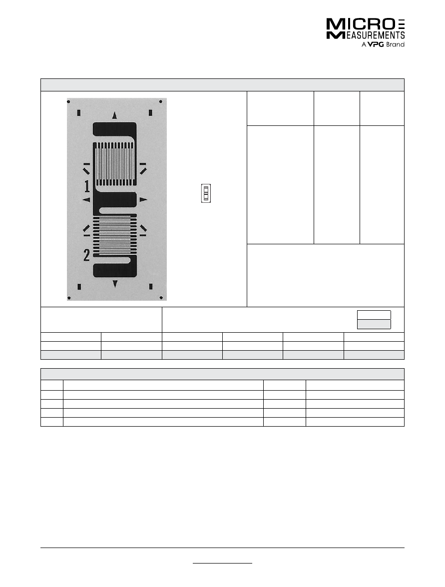
For technical questions, contact
mm@vpgsensors.com
www.micro-measurements.com
66
Document No.: 11076
Revision: 22-Sep-2015
050TG
General Purpose Strain Gages—Tee Rosette
General Purpose Strain Gages—Tee Rosette
GAGE PATTERN DATA
actual size
GAGE
DESIGNATION
See Note 1, 3
RESISTANCE
(OHMS)
See Note 2
OPTIONS
AVAILABLE
See Note 3
EA-XX-050TG-350
WA-XX-050TG-350
EP-08-050TG-350
SA-XX-050TG-350
350 ± 0.2%
350 ± 0.4%
350 ± 0.2%
350 ± 0.4%
L, LE
DESCRIPTION
Miniature high-resistance 90° tee rosette. Sections
have a common solder tab.
GAGE DIMENSIONS
Legend
ES = Each Section
CP = Complete Pattern
S = Section (S1 = Section 1)
M = Matrix
inch
millimeter
Gage Length
Overall Length
Grid Width
Overall Width
Matrix Length
Matrix Width
0.050 ES
0.250 CP
0.070 ES
0.070 CP
0.34
0.17
1.27 ES
6.35 CP
1.78 ES
1.78 CP
8.6
4.3
GAGE SERIES DATA
—
See Gage Series datasheet for complete specifications
Series
Description
Strain Range
Temperature Range
EA
Constantan foil in combination with a tough, flexible, polyimide backing.
±3%
–100° to +350°F (–75° to +175°C)
WA
Fully encapsulated constantan gages with high-endurance leadwires.
±2%
–100° to +400°F (–75° to +205°)
EP
Annealed constantan foil with tough, high-elongation polyimide backing.
±10%
–100° to +400°F (–75° to +205°C)
SA
Fully encapsulated constantan gages with solder dots.
±2%
–100° to +400°F (–75° to +205°C)
Note 1:
Insert desired S-T-C number in spaces marked XX.
Note 2:
Tolerance is increased when Option W, E, SE, LE, or P is specified.
Note 3:
Products with designations and options shown in
bold
are not RoHS compliant.
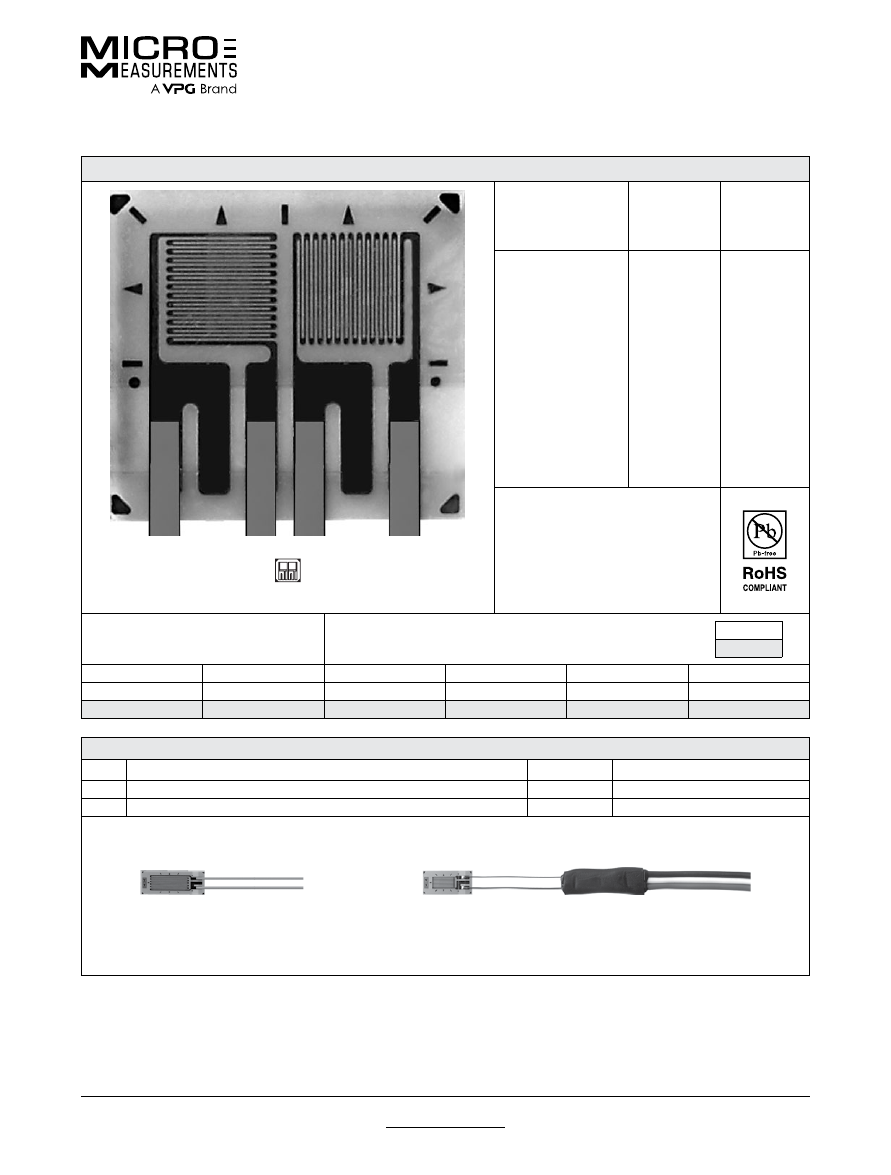
For technical questions, contact
mm@vpgsensors.com
Document No.: 11096
Revision: 23-Sep-2015
www.micro-measurements.com
67
062LT
General Purpose Strain Gages—Tee Rosette
General Purpose Strain Gages—Tee Rosette
GAGE PATTERN DATA
actual size
GAGE
DESIGNATION
See Note 1
RESISTANCE
(OHMS)
OPTIONS
AVAILABLE
L2A-XX-062LT-120
L2A-XX-062LT-350
C2A-XX-062LT-120
C2A-XX-062LT-350
120 ± 0.6%
350 ± 0.6%
120 ± 0.6%
350 ± 0.6%
DESCRIPTION
General-purpose 90° rosette.
GAGE DIMENSIONS
Legend
ES = Each Section
CP = Complete Pattern
S = Section (S1 = Section 1)
M = Matrix
inch
millimeter
Gage Length
Overall Length
Grid Width
Overall Width
Matrix Length
Matrix Width
0.062
0.164
0.070
0.170
0.210
0.230
1.52
4.17
1.78
4.32
5.33
5.84
GAGE SERIES DATA
—
See Gage Series datasheet for complete specifications
Series
Description
Strain Range
Temperature Range
L2A
Encapsulated constantan gages with preattached ribbon leads.
±3%
–100° to +250°F (–75° to +120°C)
C2A
Encapsulated constantan gages with preattached ready-to-use cables.
±3%
–60° to +180°F (–50° to +80°C)
Example of an
L2A Construction
Example of an
C2A Construction
Note 1:
Insert desired S-T-C number in spaces marked XX.
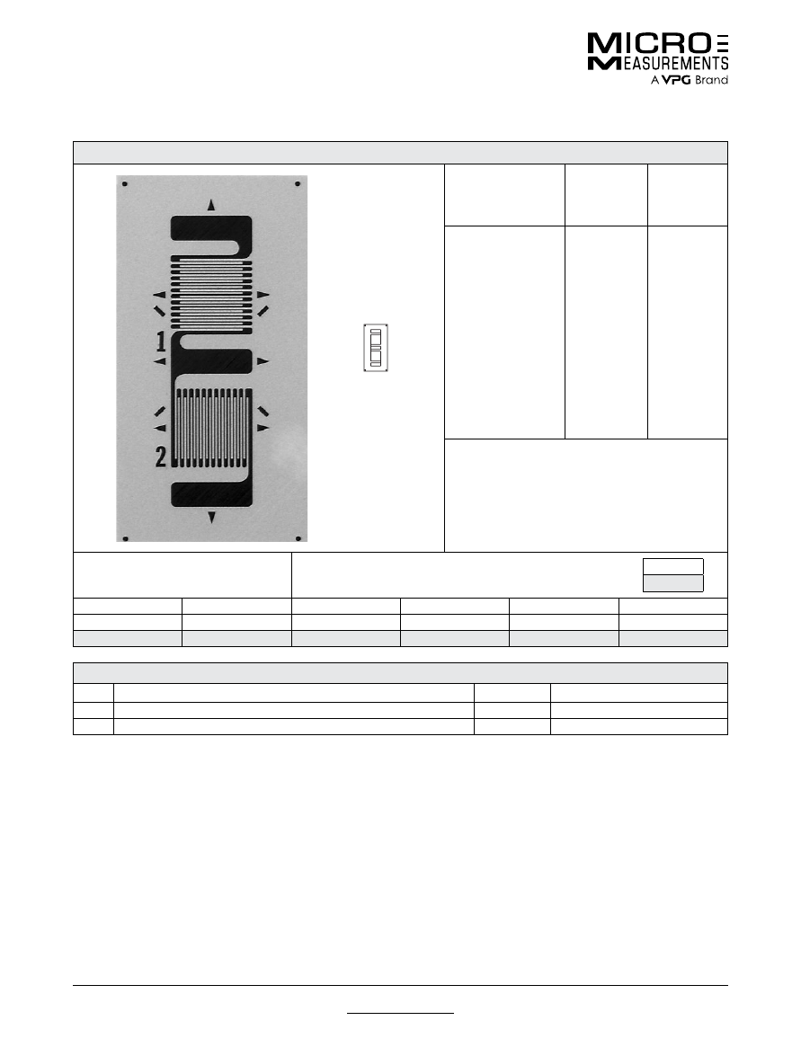
For technical questions, contact
mm@vpgsensors.com
www.micro-measurements.com
68
Document No.: 11099
Revision: 26-Oct-2015
062TJ
General Purpose Strain Gages—Tee Rosette
General Purpose Strain Gages—Tee Rosette
GAGE PATTERN DATA
actual size
GAGE
DESIGNATION
See Note 1, 2
RESISTANCE
(OHMS)
OPTIONS
AVAILABLE
See Note 2
EA-XX-062TJ-120
EA-XX-062TJ-350
SA-XX-062TJ-120
SA-XX-062TJ-350
120 ± 0.2%
350 ± 0.2%
120 ± 0.4%
350 ± 0.4%
DESCRIPTION
General-purpose 90° tee rosette. Sections have a
common solder tab.
GAGE DIMENSIONS
Legend
ES = Each Section
CP = Complete Pattern
S = Section (S1 = Section 1)
M = Matrix
inch
millimeter
Gage Length
Overall Length
Grid Width
Overall Width
Matrix Length
Matrix Width
0.062 ES
0.295 CP
0.080 ES
0.080 CP
0.38
0.19
1.57 ES
7.49 CP
2.03 ES
2.03 CP
12.2
4.8
GAGE SERIES DATA
—
See Gage Series datasheet for complete specifications
Series
Description
Strain Range
Temperature Range
EA
Constantan foil in combination with a tough, flexible, polyimide backing.
±3%
–100° to +350°F (–75° to +175°C)
SA
Fully encapsulated constantan gages with solder dots.
±2%
–100° to +400°F (–75° to +205°C)
Note 1:
Insert desired S-T-C number in spaces marked XX.
Note 2:
Tolerance is increased when Option W, E, SE, LE, or P is specified.
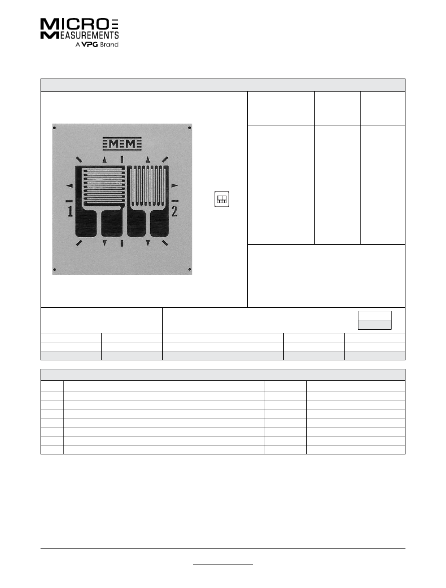
For technical questions, contact
mm@vpgsensors.com
Document No.: 11100
Revision: 26-Oct-2015
www.micro-measurements.com
69
062TT
General Purpose Strain Gages—Tee Rosette
General Purpose Strain Gages—Tee Rosette
GAGE PATTERN DATA
actual size
GAGE
DESIGNATION
See Note 1, 3
RESISTANCE
(OHMS)
See Note 2
OPTIONS
AVAILABLE
See Note 3
EA-XX-062TT-120
EA-XX-062TT-350
EK-XX-062TT-350
WA-XX-062TT-120
WA-XX-062TT-350
WK-XX-062TT-350
EP-XX-062TT-120
EP-XX-062TT-350
SA-XX-062TT-120
SA-XX-062TT-350
SK-XX-062TT-350
120 ± 0.2%
350 ± 0.2%
350 ± 0.2%
120 ± 0.4%
350 ± 0.4%
350 ± 0.4%
120 ± 0.2%
350 ± 0.2%
120 ± 0.4%
350 ± 0.4%
350 ± 0.4%
W, E, L. LE
W, E, L. LE
W,
SE
W*
W*
W*
DESCRIPTION
General-purpose 90° tee rosette. Sections are
electrically independent. EK-Series gages are supplied
with duplex copper pads (DP) when optional feature W
or SE is not specified.
GAGE DIMENSIONS
Legend
ES = Each Section
CP = Complete Pattern
S = Section (S1 = Section 1)
M = Matrix
inch
millimeter
Gage Length
Overall Length
Grid Width
Overall Width
Matrix Length
Matrix Width
0.062 ES
0.133 CP
0.075 ES
0.168 CP
0.28
0.26
1.57 ES
3.38 CP
1.91 ES
4.27 CP
7.1
6.6
GAGE SERIES DATA
—
See Gage Series datasheet for complete specifications
Series
Description
Strain Range
Temperature Range
EA
Constantan foil in combination with a tough, flexible, polyimide backing.
±3%
–100° to +350°F (–75° to +175°C)
EK
K-alloy foil in combination with a tough, flexible polyimide backing.
±1.5%
–320° to +350°F (–195° to +175°C)
WA
Fully encapsulated constantan gages with high-endurance leadwires.
±2%
–100° to +400°F (–75° to +205°)
WK
Fully encapsulated K-alloy gages with high-endurance leadwires.
±1.5%
–452° to +550°F (–269° to +290°C)
EP
Annealed constantan foil with tough, high-elongation polyimide backing.
±10%
–100° to +400°F (–75° to +205°C)
SA
Fully encapsulated constantan gages with solder dots.
±2%
–100° to +400°F (–75° to +205°C)
SK
Fully encapsulated K-alloy gages with solder dots.
±1.5%
–452° to +450°F (–269° to +230°C)
Note 1:
Insert desired S-T-C number in spaces marked XX.
Note 2:
Tolerance is increased when Option W, E, SE, LE, or P is specified.
Note 3:
Products with designations and options shown in
bold
are not RoHS compliant.
*Options available but not normally recommended. See Optional Features datasheet for details.
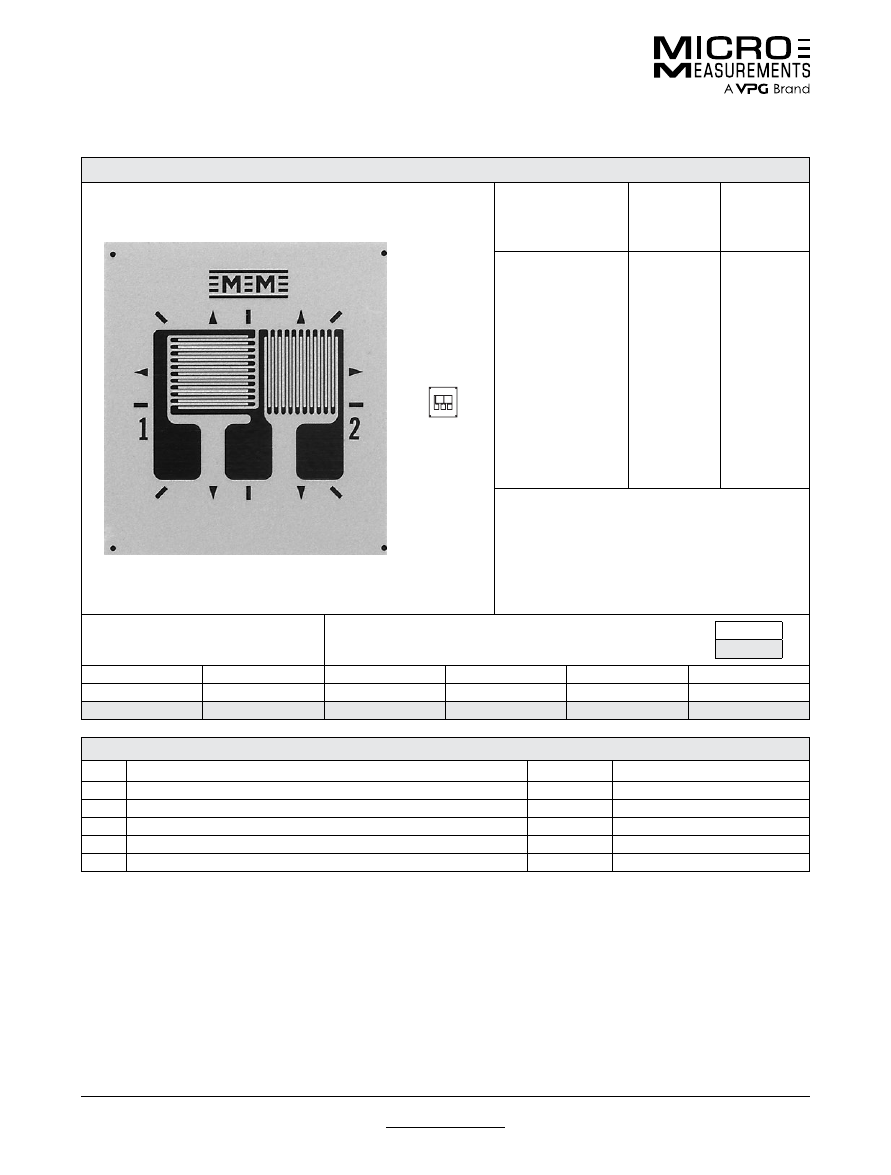
For technical questions, contact
mm@vpgsensors.com
www.micro-measurements.com
70
Document No.: 11123
Revision: 03-Nov-2015
062TZ
General Purpose Strain Gages—Tee Rosette
General Purpose Strain Gages—Tee Rosette
GAGE PATTERN DATA
actual size
GAGE
DESIGNATION
See Note 1, 3
RESISTANCE
(OHMS)
See Note 2
OPTIONS
AVAILABLE
See Note 3
EA-XX-062TZ-350
WA-XX-062TZ-350
WK-XX-062TZ-120
SA-XX-062TZ-350
SK-XX-062TZ-120
350 ± 0.2%
350 ± 0.4%
120 ± 0.4%
350 ± 0.4%
120 ± 0.4%
W, E, L, LE
DESCRIPTION
General-purpose 90° tee rosette. Similar in geometry
to 062TT pattern except common tab version.
GAGE DIMENSIONS
Legend
ES = Each Section
CP = Complete Pattern
S = Section (S1 = Section 1)
M = Matrix
inch
millimeter
Gage Length
Overall Length
Grid Width
Overall Width
Matrix Length
Matrix Width
0.062 ES
0.133 CP
0.075 ES
0.168 CP
0.28
0.26
1.57 ES
3.38 CP
1.91 ES
4.27 CP
7.1
6.6
GAGE SERIES DATA
—
See Gage Series datasheet for complete specifications
Series
Description
Strain Range
Temperature Range
EA
Constantan foil in combination with a tough, flexible, polyimide backing.
±3%
–100° to +350°F (–75° to +175°C)
WA
Fully encapsulated constantan gages with high-endurance leadwires.
±2%
–100° to +400°F (–75° to +205°)
WK
Fully encapsulated K-alloy gages with high-endurance leadwires.
±1.5%
–452° to +550°F (–269° to +290°C)
SA
Fully encapsulated constantan gages with solder dots.
±2%
–100° to +400°F (–75° to +205°C)
SK
Fully encapsulated K-alloy gages with solder dots.
±1.5%
–452° to +450°F (–269° to +230°C)
Note 1:
Insert desired S-T-C number in spaces marked XX.
Note 2:
Tolerance is increased when Option W, E, SE, LE, or P is specified.
Note 3:
Products with designations and options shown in
bold
are not RoHS compliant.
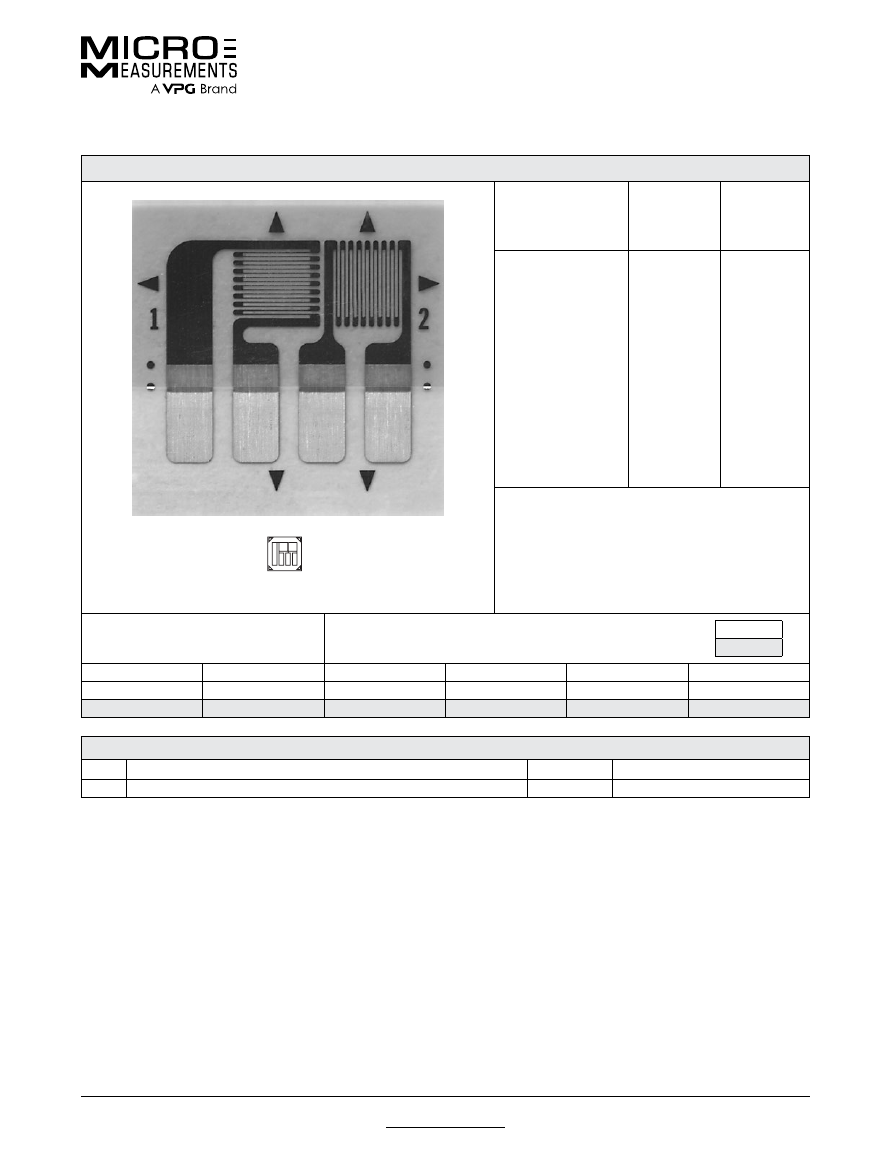
For technical questions, contact
mm@vpgsensors.com
Document No.: 11125
Revision: 25-Aug-2015
www.micro-measurements.com
71
062UT
General Purpose Strain Gages—Tee Rosette
General Purpose Strain Gages—Tee Rosette
GAGE PATTERN DATA
actual size
GAGE
DESIGNATION
See Note 1
RESISTANCE
(OHMS)
OPTIONS
AVAILABLE
See Note 2
CEA-XX-062UT-120
CEA-XX-062UT-350
120 ± 0.4%
350 ± 0.4%
P2
P2
DESCRIPTION
Small general-purpose two-element 90° tee rosette.
Exposed solder tab area 0.07 x 0.04 in (1.8 x 1.0 mm).
GAGE DIMENSIONS
Legend
ES = Each Section
CP = Complete Pattern
S = Section (S1 = Section 1)
M = Matrix
inch
millimeter
Gage Length
Overall Length
Grid Width
Overall Width
Matrix Length
Matrix Width
0.062 ES
0.205 CP
0.080 ES
0.225 CP
0.31
0.31
1.57 ES
5.21 CP
2.03 ES
5.72 CP
7.9
7.9
GAGE SERIES DATA
—
See Gage Series datasheet for complete specifications
Series
Description
Strain Range
Temperature Range
CEA
Universal general-purpose strain gages.
±3%
–100° to +350°F (–75° to +175°C)
Note 1:
Insert desired S-T-C number in spaces marked XX.
Note 2:
Products with designations and options shown in bold are not RoHS compliant.
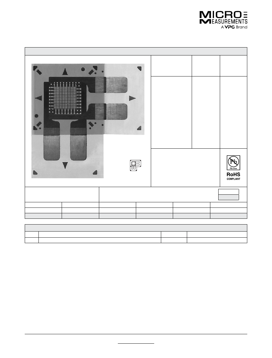
For technical questions, contact
mm@vpgsensors.com
www.micro-measurements.com
72
Document No.: 11190
Revision: 25-Aug-2015
062WT
General Purpose Strain Gages—Tee Rosette
General Purpose Strain Gages—Tee Rosette
GAGE PATTERN DATA
actual size
GAGE
DESIGNATION
See Note 1
RESISTANCE
(OHMS)
OPTIONS
AVAILABLE
CEA-XX-062WT-120
CEA-XX-062WT-350
120 ± 0.5%
350 ± 0.5%
DESCRIPTION
Small two-element 90° stacked
rosette. Exposed solder tab area 0.07
x 0.04 in (1.8 x 1.0 mm). Maximum
operating temperature +150°F
(+65°C).
GAGE DIMENSIONS
Legend
ES = Each Section
CP = Complete Pattern
S = Section (S1 = Section 1)
M = Matrix
inch
millimeter
Gage Length
Overall Length
Grid Width
Overall Width
Matrix Length
Matrix Width
0.062 ES
0.235 CP
0.120 ES
0.235 CP
0.33
0.33
1.57 ES
5.97 CP
3.05 ES
5.97 CP
8.3
8.3
GAGE SERIES DATA
—
See Gage Series datasheet for complete specifications
Series
Description
Strain Range
Temperature Range
CEA
Universal general-purpose strain gages.
±3%
–100° to +150°F (–75° to +65°C)
Note 1:
Insert desired S-T-C number in spaces marked XX.
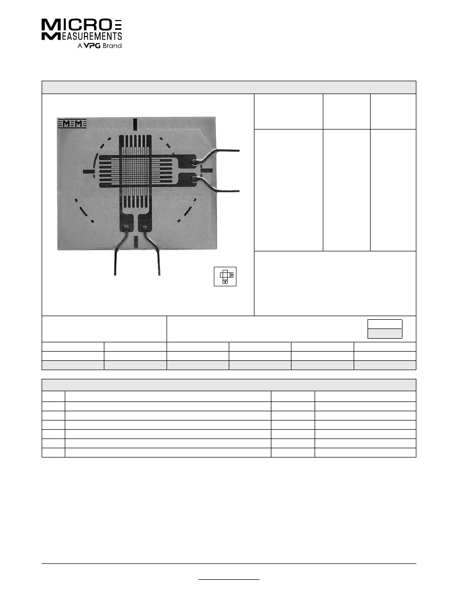
For technical questions, contact
mm@vpgsensors.com
Document No.: 11192
Revision: 03-Nov-2015
www.micro-measurements.com
73
120WT
General Purpose Strain Gages—Tee Rosette
General Purpose Strain Gages—Tee Rosette
GAGE PATTERN DATA
actual size
GAGE
DESIGNATION
See Note 1, 2
RESISTANCE
(OHMS)
OPTIONS
AVAILABLE
See Note 2
WA-XX-120WT-120
WA-XX-120WT-350
WD-DY-120WT-350
WK-XX-120WT-120
WK-XX-120WT-350
SA-XX-120WT-120
SA-XX-120WT-350
SK-XX-120WT-120
SK-XX-120WT-350
SD-DY-120WT-350
120 ± 0.5%
350 ± 0.5%
350 ± 0.5%
120 ± 0.5%
350 ± 0.5%
120 ± 0.5%
350 ± 0.5%
120 ± 0.5%
350 ± 0.5%
350 ± 0.5%
DESCRIPTION
Two-element 90° tee stacked rosette. See also 125WT
pattern.
GAGE DIMENSIONS
Legend
ES = Each Section
CP = Complete Pattern
S = Section (S1 = Section 1)
M = Matrix
inch
millimeter
Gage Length
Overall Length
Grid Width
Overall Width
Matrix Length
Matrix Width
0.120 ES
0.34 M
0.080 ES
0.040 M
0.34
0.40
3.05 ES
8.6 M
2.03 ES
10.2 M
8.6
10.2
GAGE SERIES DATA
—
See Gage Series datasheet for complete specifications
Series
Description
Strain Range
Temperature Range
WA
Fully encapsulated constantan gages with high-endurance leadwires.
±2%
–100° to +400°F (–75° to +205°)
WD
Fully encapsulated isoelastic gages with high-endurance leadwires.
±1.5%
–320° to +500°F (–195° to +260°C)
WK
Fully encapsulated K-alloy gages with high-endurance leadwires.
±1.5%
–452° to +550°F (–269° to +290°C)
SA
Fully encapsulated constantan gages with solder dots.
±2%
–100° to +400°F (–75° to +205°C)
SK
Fully encapsulated K-alloy gages with solder dots.
±1.5%
–452° to +450°F (–269° to +230°C)
SD
Equivalent to WD Series, but with solder dots instead of leadwires.
±1.5%
–320° to +400°F (–195° to +205°C)
Note 1:
Insert desired S-T-C number in spaces marked XX.
Note 2:
Products with designations and options shown in bold are not RoHS compliant.
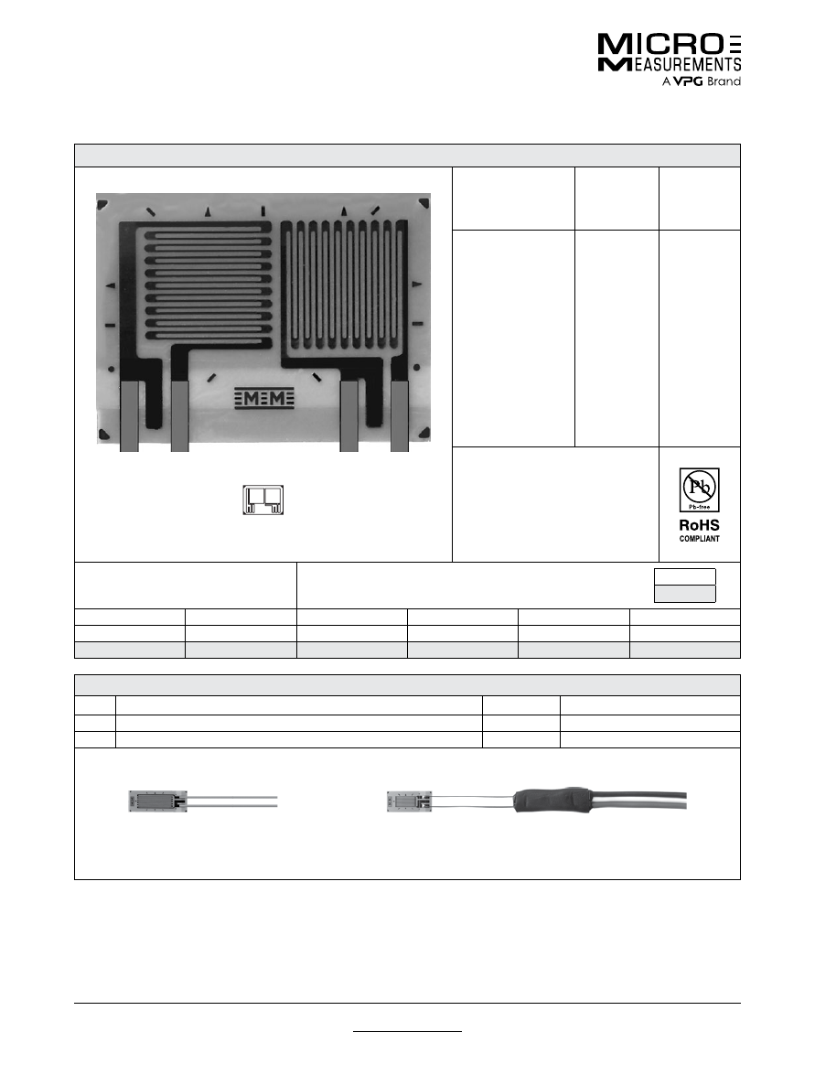
For technical questions, contact
mm@vpgsensors.com
www.micro-measurements.com
74
Document No.: 11199
Revision: 03-Nov-2015
125LT
General Purpose Strain Gages—Tee Rosette
General Purpose Strain Gages—Tee Rosette
GAGE PATTERN DATA
actual size
GAGE
DESIGNATION
See Note 1
RESISTANCE
(OHMS)
OPTIONS
AVAILABLE
L2A-XX-125LT-120
L2A-XX-125LT-350
C2A-XX-125LT-120
C2A-XX-125LT-350
120 ± 0.6%
350 ± 0.6%
120 ± 0.6%
350 ± 0.6%
DESCRIPTION
General-purpose 90° rosette.
GAGE DIMENSIONS
Legend
ES = Each Section
CP = Complete Pattern
S = Section (S1 = Section 1)
M = Matrix
inch
millimeter
Gage Length
Overall Length
Grid Width
Overall Width
Matrix Length
Matrix Width
0.125 ES
0.243 CP
0.150 ES
0.340 CP
0.290
0.400
3.18 ES
6.17 CP
3.81 ES
8.64 CP
7.37
10.16
GAGE SERIES DATA
—
See Gage Series datasheet for complete specifications
Series
Description
Strain Range
Temperature Range
L2A
Encapsulated constantan gages with preattached ribbon leads.
±3%
–100° to +250°F (–75° to +120°C)
C2A
Encapsulated constantan gages with preattached ready-to-use cables.
±3%
–60° to +180°F (–50° to +80°C)
Example of an
L2A Construction
Example of an
C2A Construction
Note 1:
Insert desired S-T-C number in spaces marked XX.
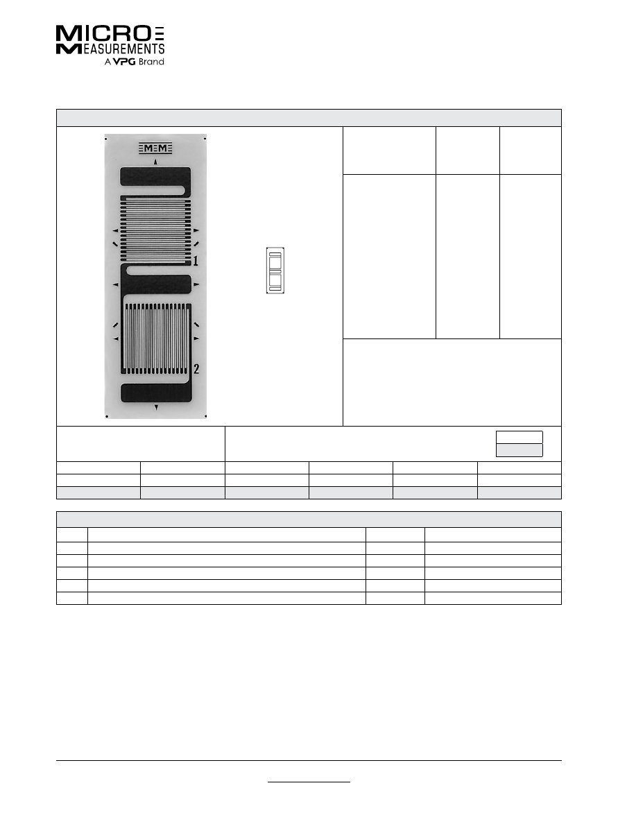
For technical questions, contact
mm@vpgsensors.com
Document No.: 11209
Revision: 09-Jul-2015
www.micro-measurements.com
75
125TG
General Purpose Strain Gages—Tee Rosette
General Purpose Strain Gages—Tee Rosette
GAGE PATTERN DATA
actual size
GAGE
DESIGNATION
See Note 1, 3
RESISTANCE
(OHMS)
See Note 2
OPTIONS
AVAILABLE
See Note 3
EA-XX-125TG-350
EK-XX-125TG-10C
WA-XX-125TG-350
SA-XX-125TG-350
SK-XX-125TG-10C
350 ± 0.2%
1000 ± 0.2%
350 ± 0.4%
350 ± 0.4%
1000 ± 0.4%
L, LE
SE
DESCRIPTION
General-purpose two-element 90° tee rosette with
high-resistance grid. Sections have a common
electrical connection. EK-Series gages are supplied
with duplex copper dots (DD) when optional feature
SE is not specified.
GAGE DIMENSIONS
Legend
ES = Each Section
CP = Complete Pattern
S = Section (S1 = Section 1)
M = Matrix
inch
millimeter
Gage Length
Overall Length
Grid Width
Overall Width
Matrix Length
Matrix Width
0.125 ES
0.500 CP
0.150 ES
0.150 CP
0.61
0.23
3.18 ES
12.70 CP
3.81 ES
3.81 CP
15.5
5.8
GAGE SERIES DATA
—
See Gage Series datasheet for complete specifications
Series
Description
Strain Range
Temperature Range
EA
Constantan foil in combination with a tough, flexible, polyimide backing.
±5%
–100° to +350°F (–75° to +175°C)
EK
K-alloy foil in combination with a tough, flexible polyimide backing.
±1.5%
–320° to +350°F (–195° to +175°C)
WA
Fully encapsulated constantan gages with high-endurance leadwires.
±2%
–100° to +400°F (–75° to +205°)
SA
Fully encapsulated constantan gages with solder dots.
±2%
–100° to +400°F (–75° to +205°C)
SK
Fully encapsulated K-alloy gages with solder dots.
±1.5%
–452° to +450°F (–269° to +230°C)
Note 1:
Insert desired S-T-C number in spaces marked XX.
Note 2:
Tolerance is increased when Option W, E, SE, LE, or P is specified.
Note 3:
Products with designations and options shown in
bold
are not RoHS compliant.

For technical questions, contact
mm@vpgsensors.com
www.micro-measurements.com
76
Document No.: 11331
Revision: 03-Nov-2015
125TM
General Purpose Strain Gages—Tee Rosette
General Purpose Strain Gages—Tee Rosette
GAGE PATTERN DATA
actual size
GAGE
DESIGNATION
See Note 1, 3
RESISTANCE
(OHMS)
See Note 2
OPTIONS
AVAILABLE
See Note 3
EA-XX-125TM-120
WA-XX-125TM-120
WK-XX-125TM-350
EP-08-125TM-120
SA-XX-125TM-120
SK-XX-125TM-350
120 ± 0.2%
120 ± 0.4%
350 ± 0.4%
120 ± 0.2%
120 ± 0.4%
350 ± 0.4%
W, E, L, LE
W*
W*
DESCRIPTION
General-purpose two-element 90° tee rosette.
Sections are electrically independent. See also 125TQ
and 125UT patterns.
GAGE DIMENSIONS
Legend
ES = Each Section
CP = Complete Pattern
S = Section (S1 = Section 1)
M = Matrix
inch
millimeter
Gage Length
Overall Length
Grid Width
Overall Width
Matrix Length
Matrix Width
0.125 ES
0.215 CP
0.150 ES
0.335 CP
0.36
0.43
3.18 ES
5.46 CP
3.81 ES
8.51 CP
9.1
10.9
GAGE SERIES DATA
—
See Gage Series datasheet for complete specifications
Series
Description
Strain Range
Temperature Range
EA
Constantan foil in combination with a tough, flexible, polyimide backing.
±5%
–100° to +350°F (–75° to +175°C)
WA
Fully encapsulated constantan gages with high-endurance leadwires.
±2%
–100° to +400°F (–75° to +205°)
WK
Fully encapsulated K-alloy gages with high-endurance leadwires.
±1.5%
–452° to +550°F (–269° to +290°C)
EP
Annealed constantan foil with tough, high-elongation polyimide backing.
±20%
–100° to +400°F (–75° to +205°C)
SA
Fully encapsulated constantan gages with solder dots.
±2%
–100° to +400°F (–75° to +205°C)
SK
Fully encapsulated K-alloy gages with solder dots.
±1.5%
–452° to +450°F (–269° to +230°C)
Note 1:
Insert desired S-T-C number in spaces marked XX.
Note 2:
Tolerance is increased when Option W, E, SE, LE, or P is specified.
Note 3:
Products with designations and options shown in
bold
are not RoHS compliant.
*Options available but not normally recommended. See Optional Features datasheet for details.
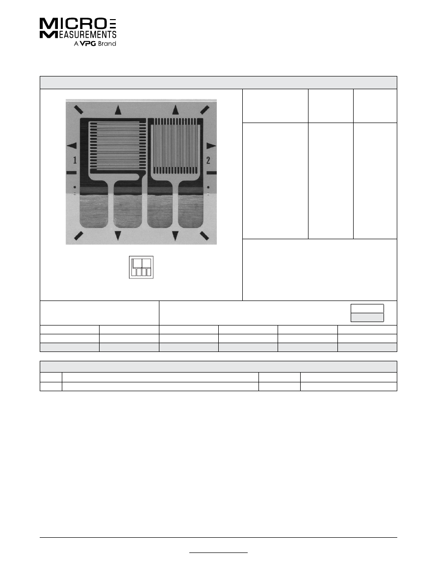
For technical questions, contact
mm@vpgsensors.com
Document No.: 11230
Revision: 25-Aug-2015
www.micro-measurements.com
77
125UT
General Purpose Strain Gages—Tee Rosette
General Purpose Strain Gages—Tee Rosette
GAGE PATTERN DATA
actual size
GAGE
DESIGNATION
See Note 1
RESISTANCE
(OHMS)
OPTIONS
AVAILABLE
See Note 1
CEA-XX-125UT-120
CEA-XX-125UT-350
120 ± 0.4%
350 ± 0.4%
P2
P2
DESCRIPTION
Two-element 90° tee rosette for general-purpose use.
Exposed solder tab area 0.10 x 0.07 in (2.5 x 1.8 mm).
GAGE DIMENSIONS
Legend
ES = Each Section
CP = Complete Pattern
S = Section (S1 = Section 1)
M = Matrix
inch
millimeter
Gage Length
Overall Length
Grid Width
Overall Width
Matrix Length
Matrix Width
0.125 ES
0.325 CP
0.165 ES
0.365 CP
0.42
0.45
3.18 ES
8.26 CP
4.19 ES
9.27 CP
10.7
11.4
GAGE SERIES DATA
—
See Gage Series datasheet for complete specifications
Series
Description
Strain Range
Temperature Range
CEA
Universal general-purpose strain gages.
±5%
–100° to +350°F (–75° to +175°C)
Note 1:
Insert desired S-T-C number in spaces marked XX.
Note 2:
Products with designations and options shown in bold are not RoHS compliant.
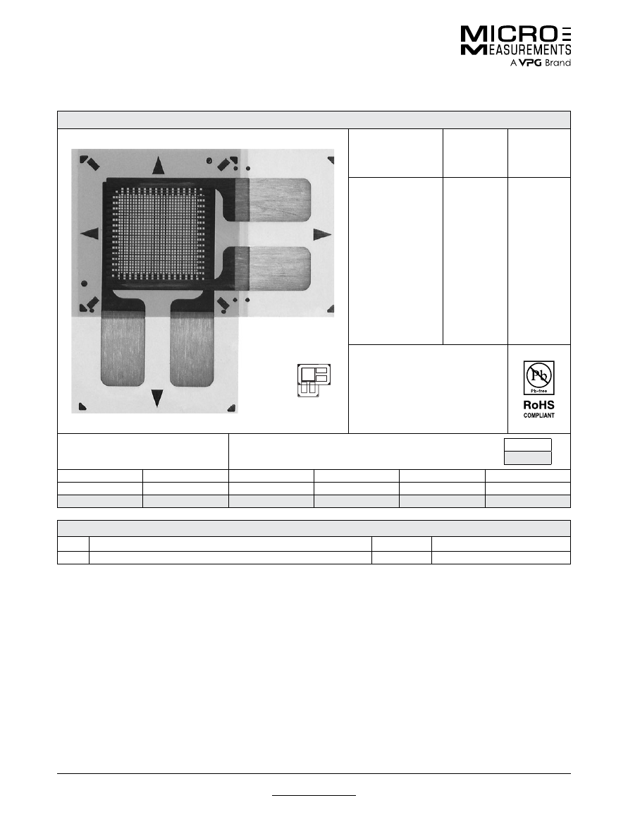
For technical questions, contact
mm@vpgsensors.com
www.micro-measurements.com
78
Document No.: 11243
Revision: 03-Nov-2015
125WT
General Purpose Strain Gages—Tee Rosette
General Purpose Strain Gages—Tee Rosette
GAGE PATTERN DATA
actual size
GAGE
DESIGNATION
See Note 1
RESISTANCE
(OHMS)
OPTIONS
AVAILABLE
CEA-XX-125WT-120
CEA-XX-125WT-350
120 ± 0.5%
350 ± 0.5%
DESCRIPTION
Two-element 90° tee stacked rosette.
Exposed solder tab area 0.10 x 0.07
in [2.5 x 1.8 mm]. Maximum operating
temperature +150°F [+65°C].
GAGE DIMENSIONS
Legend
ES = Each Section
CP = Complete Pattern
S = Section (S1 = Section 1)
M = Matrix
inch
millimeter
Gage Length
Overall Length
Grid Width
Overall Width
Matrix Length
Matrix Width
0.125 ES
0.325 CP
0.180 ES
0.325 CP
0.42
0.42
3.18 ES
8.2 CP
4.57 ES
8.26 CP
10.7
10.7
GAGE SERIES DATA
—
See Gage Series datasheet for complete specifications
Series
Description
Strain Range
Temperature Range
CEA
Universal general-purpose strain gages.
±3%
–100° to +150°F (–75° to +65°C)
Note 1:
Insert desired S-T-C number in spaces marked XX.
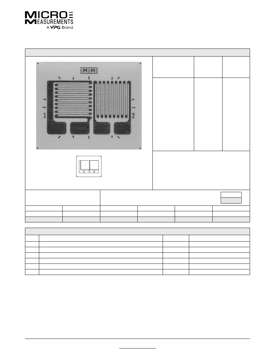
For technical questions, contact
mm@vpgsensors.com
Document No.: 11527
Revision: 20-Jan-2016
www.micro-measurements.com
79
250TM
General Purpose Strain Gages—Tee Rosette
General Purpose Strain Gages—Tee Rosette
GAGE PATTERN DATA
actual size
GAGE
DESIGNATION
See Note 1, 3
RESISTANCE
(OHMS)
See Note 2
OPTIONS
AVAILABLE
See Note 3
EA-XX-125TM-120
WA-XX-125TM-120
WK-XX-125TM-350
EP-08-125TM-120
SA-XX-125TM-120
SK-XX-125TM-350
120 ± 0.2%
120 ± 0.4%
350 ± 0.4%
120 ± 0.2%
120 ± 0.4%
350 ± 0.4%
W, E, L, LE
W*
W*
DESCRIPTION
General-purpose two-element 90° tee rosette.
Sections are electrically independent. See also 250UT
pattern.
GAGE DIMENSIONS
Legend
ES = Each Section
CP = Complete Pattern
S = Section (S1 = Section 1)
M = Matrix
inch
millimeter
Gage Length
Overall Length
Grid Width
Overall Width
Matrix Length
Matrix Width
0.250 ES
0.430 CP
0.300 ES
0.670 CP
0.53
0.75
6.35 ES
10.92 CP
7.62 ES
17.02 CP
13.5
19.1
GAGE SERIES DATA
—
See Gage Series datasheet for complete specifications
Series
Description
Strain Range
Temperature Range
EA
Constantan foil in combination with a tough, flexible, polyimide backing.
±5%
–100° to +350°F (–75° to +175°C)
WA
Fully encapsulated constantan gages with high-endurance leadwires.
±2%
–100° to +400°F (–75° to +205°)
WK
Fully encapsulated K-alloy gages with high-endurance leadwires.
±1.5%
–452° to +550°F (–269° to +290°C)
EP
Annealed constantan foil with tough, high-elongation polyimide backing.
±20%
–100° to +400°F (–75° to +205°C)
SA
Fully encapsulated constantan gages with solder dots.
±2%
–100° to +400°F (–75° to +205°C)
SK
Fully encapsulated K-alloy gages with solder dots.
±1.5%
–452° to +450°F (–269° to +230°C)
Note 1:
Insert desired S-T-C number in spaces marked XX.
Note 2:
Tolerance is increased when Option W, E, SE, LE, or P is specified.
Note 3:
Products with designations and options shown in
bold
are not RoHS compliant.
*Options available but not normally recommended. See Optional Features datasheet for details.
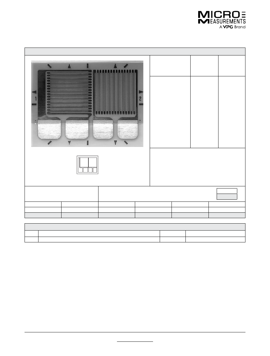
For technical questions, contact
mm@vpgsensors.com
www.micro-measurements.com
80
Document No.: 11300
Revision: 25-Aug-2015
250UT
General Purpose Strain Gages—Tee Rosette
General Purpose Strain Gages—Tee Rosette
GAGE PATTERN DATA
actual size
GAGE
DESIGNATION
See Note 1, 3
RESISTANCE
(OHMS)
See Note 2
OPTIONS
AVAILABLE
See Note 3
CEA-XX-250UT-120
CEA-XX-250UT-350
CEA-XX-250UT-10C
120 ± 0.4%
350 ± 0.4%
1000 ± 0.4%
P2
P2
P2
DESCRIPTION
Two-element 90° tee rosette for general-purpose use.
Exposed solder tab area 0.13 x 0.10 in (3.3 x 2.5 mm).
GAGE DIMENSIONS
Legend
ES = Each Section
CP = Complete Pattern
S = Section (S1 = Section 1)
M = Matrix
inch
millimeter
Gage Length
Overall Length
Grid Width
Overall Width
Matrix Length
Matrix Width
0.250 ES
0.450 CP
0.290 ES
0.650 CP
0.55
0.74
6.35 ES
11.43 CP
7.37 ES
16.51 CP
14.0
18.8
GAGE SERIES DATA
—
See Gage Series datasheet for complete specifications
Series
Description
Strain Range
Temperature Range
CEA
Universal general-purpose strain gages.
±5%
–100° to +350°F (–75° to +175°C)
Note 1:
Insert desired S-T-C number in spaces marked XX.
Note 2:
Products with designations and options shown in bold are not RoHS compliant.
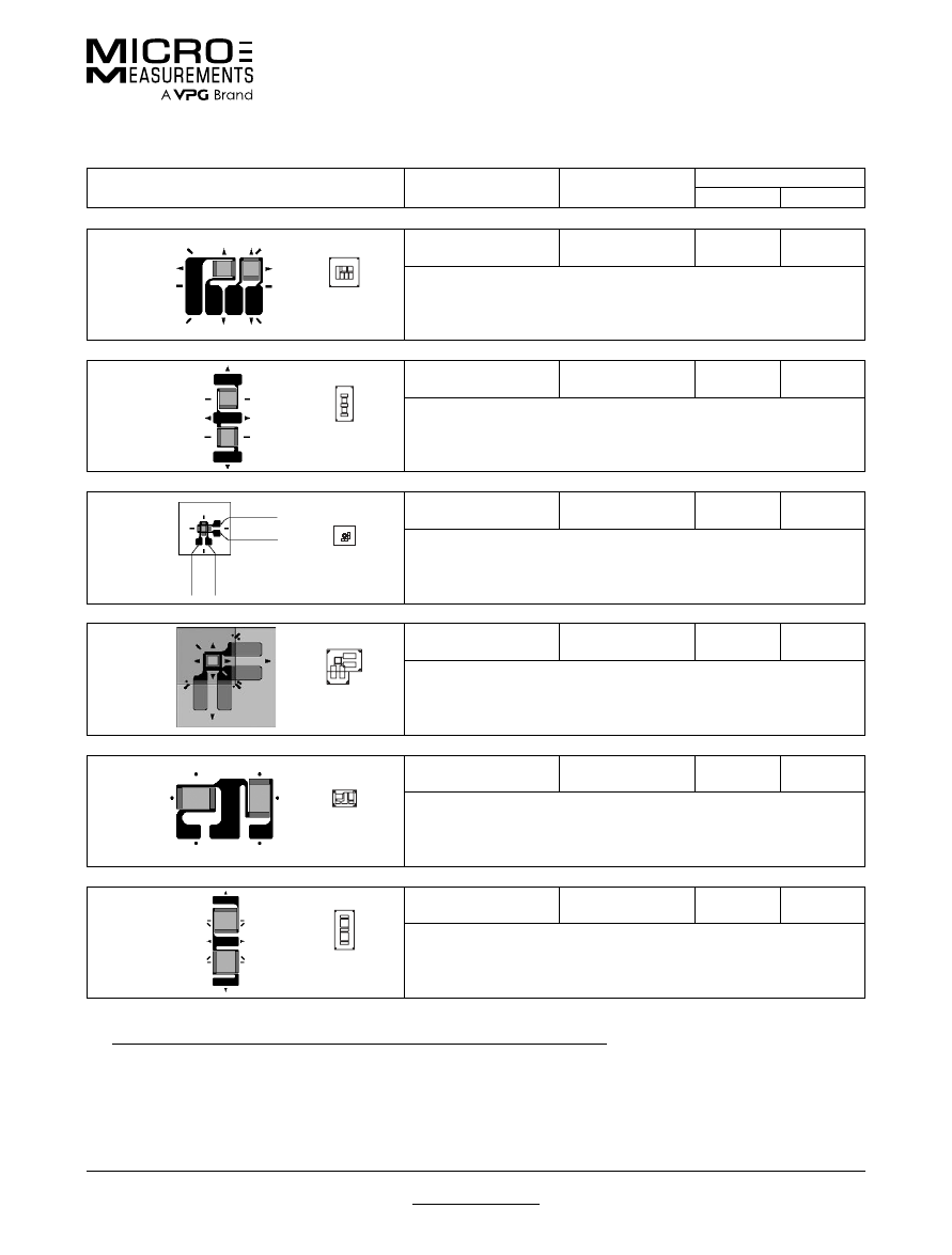
For technical questions, contact
mm@vpgsensors.com
Document No.: 11322
Revision: 21-Jan-2016
www.micro-measurements.com
81
Other Tee Rosette Patterns
General Purpose Strain Gages
General Purpose Strain Gages
GAGE PATTERN
GAGE SERIES
See Note 1
GAGE RESISTANCE
(OHMS)
GAGE LENGTH
inches
millimeters
030TU
actual size
EA, EP,
SA, SK
120, 350
0.03
0.76
Miniature 90° tee rosette. Sections are electrically independent.
Matrix size: 0.25L x 0.25W in. (6.4L x 6.4W mm)
030TY
actual size
EA, EP,
SA, SK
120, 350
0.03
0.76
Miniature 90° tee rosette with large solder tabs.
Matrix size: 0.30L x 0.15W in. (7.6L x 3.8W mm)
030WT
actual size
WA
, WK,
SA, SK
120
0.03
0.76
Miniature two-element 90° tee stacked rosette. See also 032WT pattern.
Matrix size: 0.17L x 0.19W in. (4.3L x 4.8W mm)
032WT
actual size
CEA
120
0.032
0.81
Miniature two-element 90° stacked rosette. Exposed solder tab area is 0.07 x
0.04 in (1.8 x 1.0 mm). Maximum operating temperature +150°F (+65°C).
Matrix size: 0.30L x 0.30W in. (7.6L x 7.6W mm)
044TP
actual size
EA,
SA
350
0.044
1.12
Miniature high-resistance 90° tee rosette.
Matrix size: 0.14L x 0.20W in. (3.6L x 5.1W mm)
050TG
actual size
EA,
WA
, EP,
SA
350
0.05
1.27
Miniature high-resistance 90° tee rosette. Sections have a common solder tab.
Matrix size: 0.34L x 0.17W in. (8.6L x 4.3W mm)
Note 1:
Products with designations and options shown in
bold
are not RoHS compliant.
See http://www.micro-measurements.com/stress-analysis-strain-gages/other-tee-rosettes/
for complete specifications.
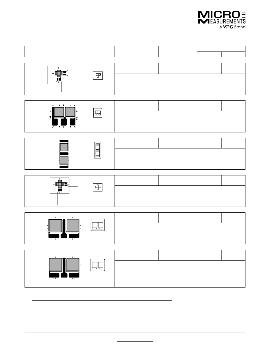
For technical questions, contact
mm@vpgsensors.com
www.micro-measurements.com
82
Document No.: 11322
Revision: 21-Jan-2016
Other Tee Rosette Patterns
General Purpose Strain Gages
GAGE PATTERN
GAGE SERIES
See Note 1
GAGE RESISTANCE
(OHMS)
GAGE LENGTH
inches
millimeters
060WT
actual size
WA
, WK,
SA, SK
120, 350, 1000
0.06
1.52
Small two-element 90° tee stacked rosette.
Matrix size: 0.24L x 0.30W in. (6.1L x 7.6W mm)
062TZ
actual size
EA,
WA
, WK,
SA, SK
120, 350
0.062
1.57
General-purpose 90° tee rosette.
Matrix size: 0.28L x 0.26W in. (7.1L x 6.6W mm)
100TG
actual size
EA,
WA, SA
350, 1000
0.1
2.54
Small high-resistance 90° tee rosette for general-purpose use.
Matrix size: 0.50L x 0.19W in. (12.7L x 4.8W mm)
120WT
actual size
WA
, WD, WK,
SA, SK,
SD
120, 350
0.12
3.05
Two-element 90° tee stacked rosette.
Matrix size: 0.34L x 0.40W in. (8.6L x 10.2W mm)
125TA
actual size
EA,
WA
, WK,
SA, SK
120, 350
0.125
3.18
General-purpose two-element 90° tee rosette. Sections have a common
electrical connection. See also 125TB pattern.
Matrix size: 0.36L x 0.41W in. (9.1L x 10.4W mm)
125TB
actual size
EA, EK,
WA
, WK,
SA,
SK
350, 1000
0.125
3.18
General-purpose two-element 90° tee rosette. Same geometry as 125TA but
with higher resistance. Sections have common electrical connection. EK-Series
gages are supplied with duplex copper dots (DD) when optional feature W or
SE is not specified.
Matrix size: 0.36L x 0.44W in. (9.1L x 11.2W mm)
Note 1:
Products with designations and options shown in
bold
are not RoHS compliant.
See http://www.micro-measurements.com/stress-analysis-strain-gages/other-tee-rosettes/
for complete specifications.
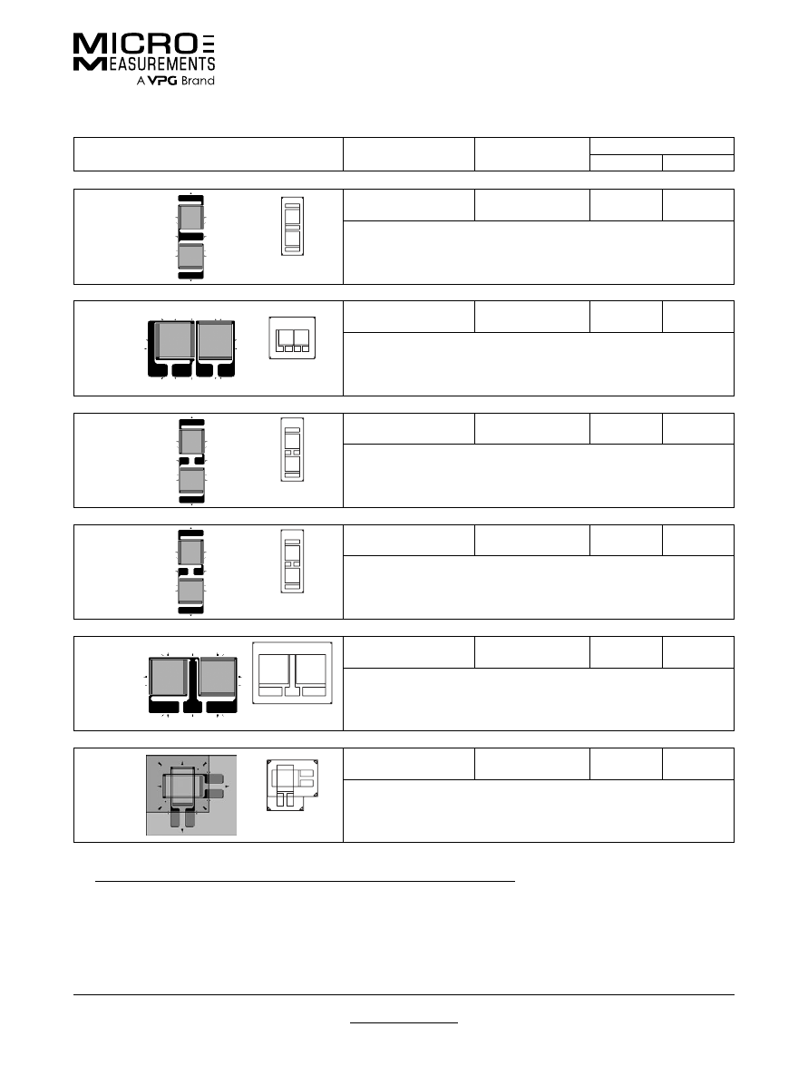
For technical questions, contact
mm@vpgsensors.com
Document No.: 11322
Revision: 21-Jan-2016
www.micro-measurements.com
83
Other Tee Rosette Patterns
General Purpose Strain Gages
GAGE PATTERN
GAGE SERIES
See Note 1
GAGE RESISTANCE
(OHMS)
GAGE LENGTH
inches
millimeters
125TF
actual size
EA,
SA, SK
120, 350
0.125
3.18
General-purpose two-element 90° tee rosette with narrow pattern geometry.
Sections have a common electrical connection.
Matrix size: 0.59L x 0.21W in. (15.0L x 5.3W mm)
125TQ
actual size
EA, ED,
WA
, WK, EP,
SA, SK
350, 1000
0.125
3.18
General-purpose two-element 90° tee rosette. EK-Series gages are supplied
with duplex copper dots (DD) when optional feature W or SE is not specified.
Matrix size: 0.42L x 0.47W in. (10.7L x 11.9W mm)
125VA
actual size
EA, EP,
SA, SK
350, 1000
0.125
3.18
General-purpose two-element 90° tee rosette with high-resistance grid. See
also 125VB pattern.
Matrix size: 0.64L x 0.23W in. (16.3L x 5.8W mm)
125VB
actual size
EA, EP,
SA, SK
120, 350
0.125
3.18
General-purpose two-element 90° tee rosette. Similar to 125TF pattern except
sections are electrically independent. See also 125VA pattern.
Matrix size: 0.64L x 0.23W in. (16.3L x 5.8W mm)
250TB
actual size
EA, EK,
WA
, WK,
SA,
SK
350, 1000
0.25
6.35
General-purpose two-element 90° tee rosette. EK-Series gages are supplied
with duplex copper pads (DP) when optional feature W or SE is not specified.
Matrix size: 0.63L x 0.81W in. (16.0L x 20.6W mm)
250WQ
actual size
CEA
350
0.25
6.35
Two-element 90° tee stacked rosette. Maximum operating temperature +150°F
(+65°C). Exposed solder tab area is 0.11 x 0.07 in (2.8 x 1.8 mm).
Matrix size: 0.55L x 0.55W in. (14.0L x 14.0W mm)
Note 1:
Products with designations and options shown in
bold
are not RoHS compliant.
See http://www.micro-measurements.com/stress-analysis-strain-gages/other-tee-rosettes/
for complete specifications.
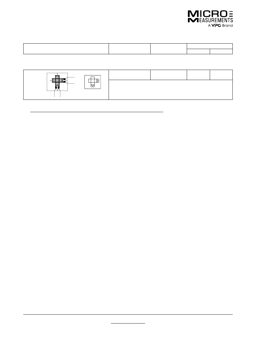
For technical questions, contact
mm@vpgsensors.com
www.micro-measurements.com
84
Document No.: 11322
Revision: 21-Jan-2016
Other Tee Rosette Patterns
General Purpose Strain Gages
250WT
actual size
WA
, WD, WK,
SA, SK,
SD
120, 350
0.25
6.35
Two-element 90° tee stacked rosette.
Matrix size: 0.51L x 0.60W in. (13.0L x 15.2W mm)
Note 1:
Products with designations and options shown in
bold
are not RoHS compliant.
See http://www.micro-measurements.com/stress-analysis-strain-gages/other-tee-rosettes/
for complete specifications.
GAGE PATTERN
GAGE SERIES
See Note 1
GAGE RESISTANCE
(OHMS)
GAGE LENGTH
inches
millimeters

For technical questions, contact
mm@vpgsensors.com
www.micro-measurements.com
85
Rectangular
Rosettes
(General-Use)
FEATURES
• Gage patterns designed for determining principle stresses
and strains
• All patterns have three grids oriented at 0°, 45° and
90° angles
• Both stacked and planar constructions available
• Gage lengths from 0.031” (0.79 mm) to 0.250” (6.35 mm)
PATTERNS
031RB .................................................. 86
031WW ................................................. 87
G1350 .................................................... 88
060WR ................................................. 89
062LR ................................................... 90
062UR ................................................. 91
062WW ................................................. 92
120WR ................................................. 93
125LR ................................................... 94
125RA .................................................. 95
125UR ................................................. 96
125WW ................................................. 97
250LR ................................................... 98
250UR ................................................. 99
250WW ............................................... 100
Other Rectangular Rosettes ............... 101
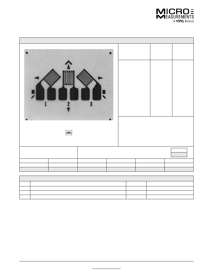
For technical questions, contact
mm@vpgsensors.com
www.micro-measurements.com
86
Document No.: 11074
Revision: 16-Nov-2015
031RB
General Purpose Strain Gages—Rectangular Pattern
General Purpose Strain Gages—Rectangular Pattern
GAGE PATTERN DATA
actual size
GAGE
DESIGNATION
See Note 1, 3
RESISTANCE
(OHMS)
See Note 2
OPTIONS
AVAILABLE
See Note 3
EA-XX-031RB-120
EP-08-031RB-120
SA-XX-031RB-120
120 ± 0.4%
120 ± 0.4%
120 ± 0.8%
E,
SE
, L, LE
DESCRIPTION
Miniature 45° rectangular single-plane rosette with
compact geometry.
GAGE DIMENSIONS
Legend
ES = Each Section
CP = Complete Pattern
S = Section (S1 = Section 1)
M = Matrix
inch
millimeter
Gage Length
Overall Length
Grid Width
Overall Width
Matrix Length
Matrix Width
0.031ES
0.085 CP
0.031 ES
0.175 CP
0.19
0.30
0.79 ES
2.16 CP
0.79 ES
4.45 CP
4.8
6.1
GAGE SERIES DATA
—
See Gage Series datasheet for complete specifications
Series
Description
Strain Range
Temperature Range
EA
Constantan foil in combination with a tough, flexible, polyimide backing.
±3%
–100° to +350°F (–75° to +175°C)
EP
Annealed constantan foil with tough, high-elongation polyimide backing.
±10%
–100° to +400°F (–75° to +205°C)
SA
Fully encapsulated constantan gages with solder dots.
±2%
–100° to +400°F (–75° to +205°C)
Note 1:
Insert desired S-T-C number in spaces marked XX.
Note 2:
Tolerance is increased when Option W, E, SE, LE, or P is specified.
Note 3:
Products with designations and options shown in
bold
are not RoHS compliant.
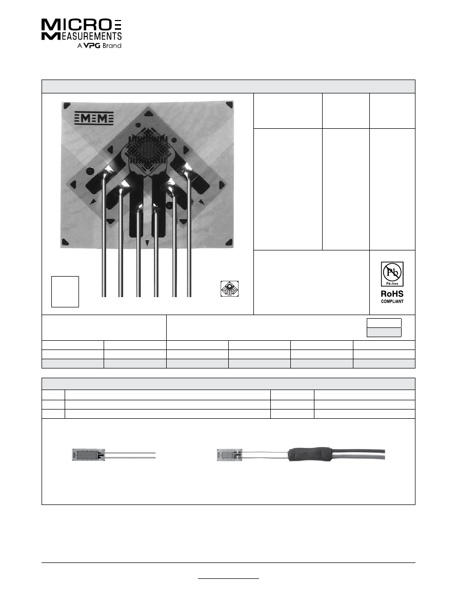
For technical questions, contact
mm@vpgsensors.com
Document No.: 11250
Revision: 17-Nov-2015
www.micro-measurements.com
87
031WW
General Purpose Strain Gages—Stacked Rosette
General Purpose Strain Gages—Stacked Rosette
GAGE PATTERN DATA
actual size
C2A
version
shown
GAGE
DESIGNATION
See Note 1
RESISTANCE
(OHMS)
OPTIONS
AVAILABLE
L2A-XX-031WW-120
L2A-XX-031WW-350
C2A-XX-031WW-120
C2A-XX-031WW-350
120 ± 0.6%
350 ± 0.6%
120 ± 0.6%
350 ± 0.6%
DESCRIPTION
Stacked, 0°-45°-90° rosette for use in
applications involving limited gaging
areas or steep strain gradients.
GAGE DIMENSIONS
Legend
ES = Each Section
CP = Complete Pattern
S = Section (S1 = Section 1)
M = Matrix
inch
millimeter
Gage Length
Overall Length
Grid Width
Overall Width
Matrix Length
Matrix Width
0.031 ES
0.206 CP
0.070 ES
0.227 CP
0.278
0.315
0.79 ES
5.23 CP
1.79 ES
5.77 CP
7.06
8.00
GAGE SERIES DATA
—
See Gage Series datasheet for complete specifications
Series
Description
Strain Range Temperature Range (See Note 2)
L2A
Encapsulated constantan gages with preattached ribbon leads.
±3%
–100° to +150°F (–75° to +65°C)
C2A
Encapsulated constantan gages with preattached ready-to-use cables.
±3%
–60° to +150°F (–50° to +65°C)
Example of an
L2A Construction
Example of an
C2A Construction
Note 1:
Insert desired S-T-C number in spaces marked XX.
Note 2:
Upper use range is reduced to these values for stacked patterns.
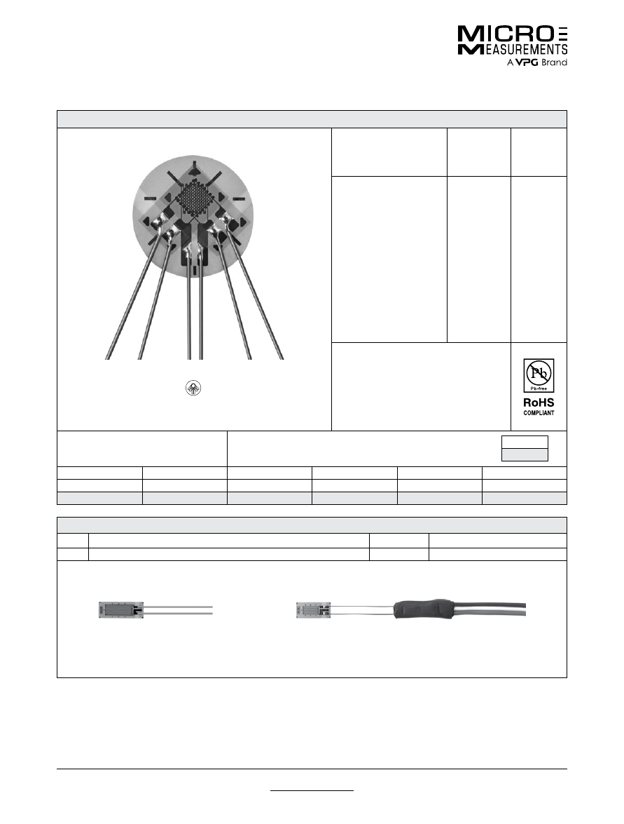
For technical questions, contact
mm@vpgsensors.com
www.micro-measurements.com
88
Document No.: 11377
Revision: 03-Feb-2016
G1350
General Purpose Strain Gages—Stacked Rosette
General Purpose Strain Gages—Stacked Rosette
GAGE PATTERN DATA
actual size
GAGE
DESIGNATION
See Note 1
RESISTANCE
(OHMS)
OPTIONS
AVAILABLE
L2A-XX-G1350-120/SP70*
C2A-XX-G1350-120/SP70*
120 ± 0.6%
120 ± 0.6%
DESCRIPTION
Stacked, 0°-45°-90° rosette for use in
applications involving limited gaging areas
or steep strain gradients. The matrix has a
circular trim (SP70).
GAGE DIMENSIONS
Legend
ES = Each Section
CP = Complete Pattern
S = Section (S1 = Section 1)
M = Matrix
inch
millimeter
Gage Length
Overall Length
Grid Width
Overall Width
Matrix Length
Matrix Width
0.040 ES
0.144 CP
0.045 ES
0.147 CP
0.20
0.20
1.0 ES
3.66 CP
1.14 ES
3.73 CP
5.1
5.1
GAGE SERIES DATA
—
See Gage Series datasheet for complete specifications
Series
Description
Strain Range
Temperature Range
C2A
Encapsulated constantan gages with preattached ready-to-use cables.
±3%
–60° to +150°F (–50° to +66°C)
Example of an
L2A Construction
Example of an
C2A Construction
Note 1:
Insert desired S-T-C number in spaces marked XX.
*SP70: circular trim of matrix.
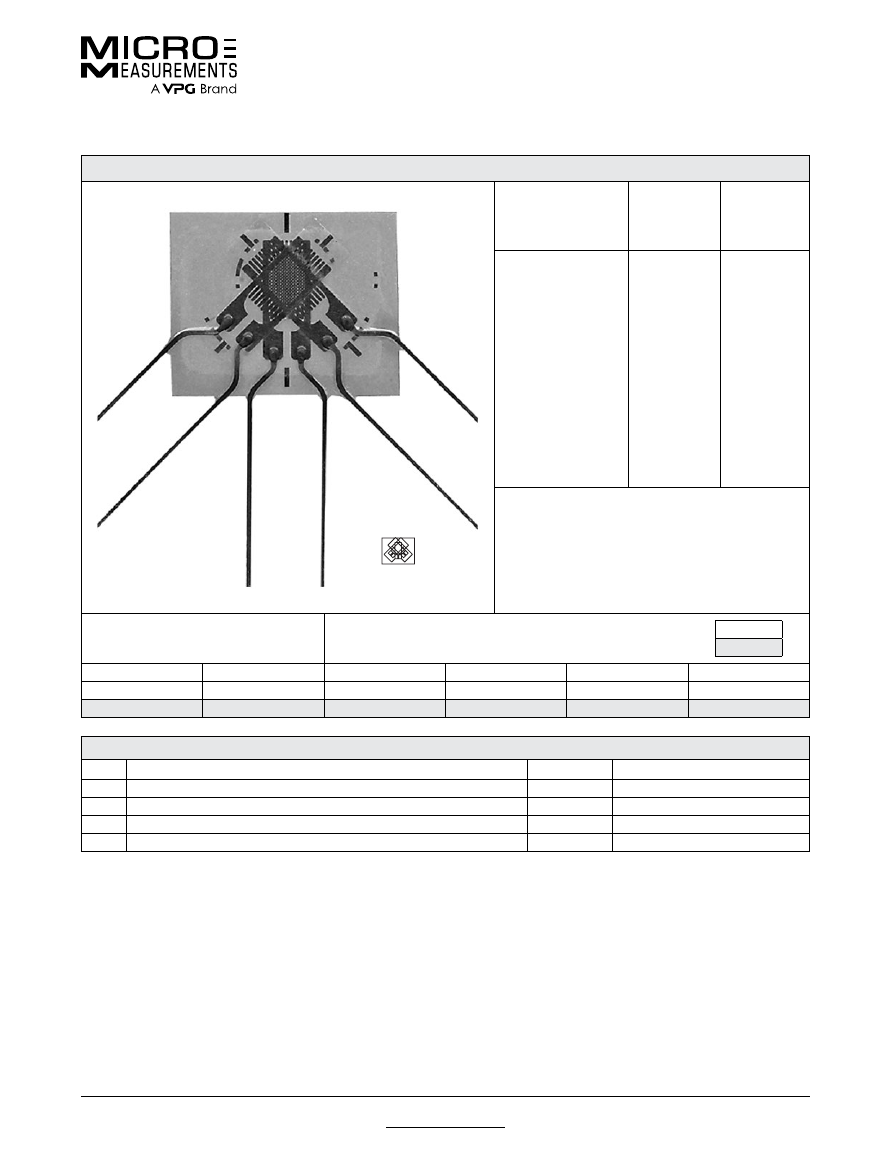
For technical questions, contact
mm@vpgsensors.com
Document No.: 11077
Revision: 17-Nov-2015
www.micro-measurements.com
89
060WR
General Purpose Strain Gages—Rectangular Rosette
General Purpose Strain Gages—Rectangular Rosette
GAGE PATTERN DATA
actual size
GAGE
DESIGNATION
See Note 1, 2
RESISTANCE
(OHMS)
OPTIONS
AVAILABLE
See Note 2
WA-XX-060WR-120
WK-XX-060WR-120
WK-XX-060WR-350
WK-XX-060WR-10C
SA-XX-060WR-120
SK-XX-060WR-120
SK-XX-060WR-350
SK-XX-060WR-10C
120 ± 0.5%
120 ± 0.5%
350 ± 0.5%
1000 ± 0.5%
120 ± 0.5%
120 ± 0.5%
350 ± 0.5%
1000 ± 0.5%
DESCRIPTION
Small three-element 45° rectangular stacked rosette
GAGE DIMENSIONS
Legend
ES = Each Section
CP = Complete Pattern
S = Section (S1 = Section 1)
M = Matrix
inch
millimeter
Gage Length
Overall Length
Grid Width
Overall Width
Matrix Length
Matrix Width
0.060 ES
0.24 M
0.060 ES
0.30 M
0.24
0.30
1.52 ES
6.1 M
1.52 ES
7.6 M
6.1
7.6
GAGE SERIES DATA
—
See Gage Series datasheet for complete specifications
Series
Description
Strain Range
Temperature Range
WA
Fully encapsulated constantan gages with high-endurance leadwires.
±2%
–100° to +400°F (–75° to +205°)
WK
Fully encapsulated K-alloy gages with high-endurance leadwires.
±1.5%
–452° to +550°F (–269° to +290°C)
SA
Fully encapsulated constantan gages with solder dots.
±2%
–100° to +400°F (–75° to +205°C)
SK
Fully encapsulated K-alloy gages with solder dots.
±1.5%
–452° to +450°F (–269° to +230°C)
Note 1:
Insert desired S-T-C number in spaces marked XX.
Note 2:
Products with designations and options shown in bold are not RoHS compliant.
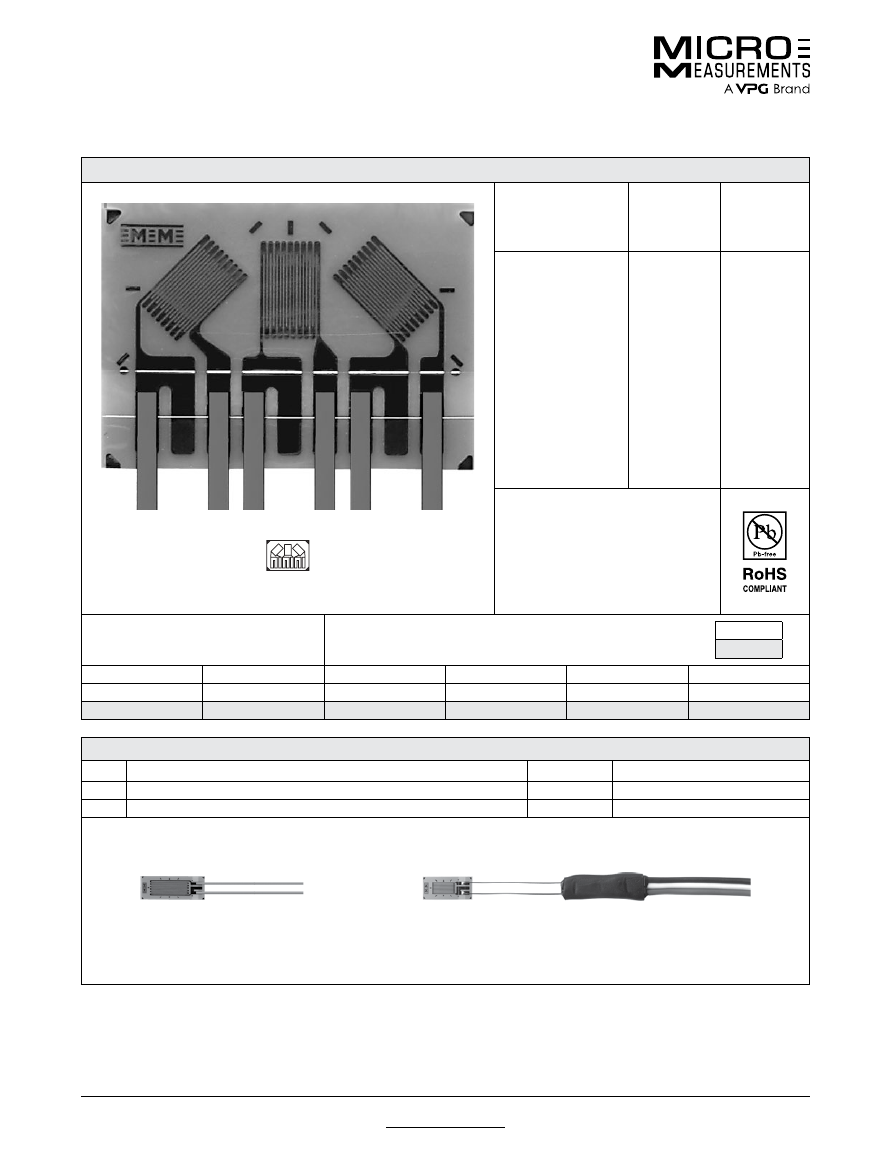
For technical questions, contact
mm@vpgsensors.com
www.micro-measurements.com
90
Document No.: 11095
Revision: 17-Nov-2015
062LR
General Purpose Strain Gages—Rectangular Rosette
General Purpose Strain Gages—Rectangular Rosette
GAGE PATTERN DATA
actual size
GAGE
DESIGNATION
See Note 1
RESISTANCE
(OHMS)
OPTIONS
AVAILABLE
L2A-XX-062LR-120
L2A-XX-062LR-350
C2A-XX062LR-120
C2A-XX-062LR-350
120 ± 0.6%
350 ± 0.6%
120 ± 0.6%
350 ± 0.6%
DESCRIPTION
Small 45° rectangular single-plane
rosette.
GAGE DIMENSIONS
Legend
ES = Each Section
CP = Complete Pattern
S = Section (S1 = Section 1)
M = Matrix
inch
millimeter
Gage Length
Overall Length
Grid Width
Overall Width
Matrix Length
Matrix Width
0.062
0.185
0.050
0.260
0.277
0.410
1.52
4.70
1.27
6.60
7.04
10.41
GAGE SERIES DATA
—
See Gage Series datasheet for complete specifications
Series
Description
Strain Range
Temperature Range
L2A
Encapsulated constantan gages with preattached ribbon leads.
±3%
–100° to +250°F (–75° to +120°C)
C2A
Encapsulated constantan gages with preattached ready-to-use cables.
±3%
–60° to +180°F (–50° to +80°C)
Example of an
L2A Construction
Example of an
C2A Construction
Note 1:
Insert desired S-T-C number in spaces marked XX.
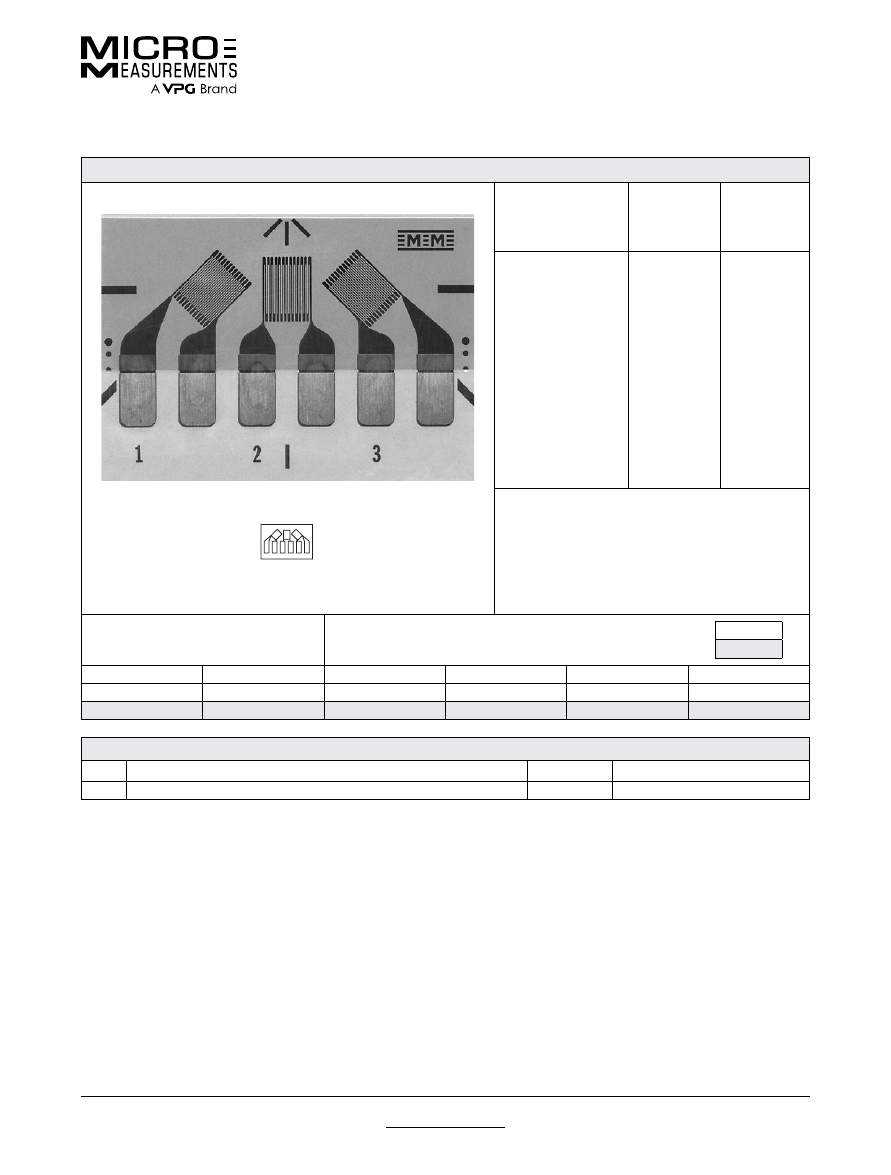
For technical questions, contact
mm@vpgsensors.com
Document No.: 11124
Revision: 26-Aug-2015
www.micro-measurements.com
91
062UR
General Purpose Strain Gages—Rectangular Rosette
General Purpose Strain Gages—Rectangular Rosette
GAGE PATTERN DATA
actual size
GAGE
DESIGNATION
See Note 1
RESISTANCE
(OHMS)
OPTIONS
AVAILABLE
See Note 2
CEA-XX-062UR-120
CEA-XX-062UR-350
120 ± 0.4%
350 ± 0.4%
P2
P2
DESCRIPTION
Small 45° rectangular single-plane rosette in a
compact geometry. Exposed solder tab area 0.07 x
0.04 in (1.8 x 1.0 mm).
GAGE DIMENSIONS
Legend
ES = Each Section
CP = Complete Pattern
S = Section (S1 = Section 1)
M = Matrix
inch
millimeter
Gage Length
Overall Length
Grid Width
Overall Width
Matrix Length
Matrix Width
0.062 ES
0.222 CP
0.062 ES
0.420 CP
0.32
0.48
1.57 ES
5.64 CP
1.57 ES
10.67 CP
8.1
12.2
GAGE SERIES DATA
—
See Gage Series datasheet for complete specifications
Series
Description
Strain Range
Temperature Range
CEA
Universal general-purpose strain gages.
±3%
–100° to +350°F (–75° to +175°C)
Note 1:
Insert desired S-T-C number in spaces marked XX.
Note 2:
Products with designations and options shown in bold are not RoHS compliant.
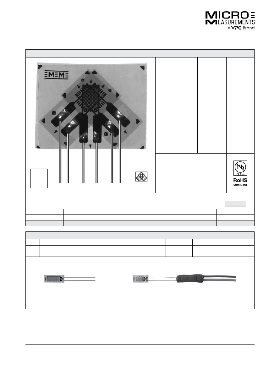
For technical questions, contact
mm@vpgsensors.com
www.micro-measurements.com
92
Document No.: 11251
Revision: 17-Nov-2015
062WW
General Purpose Strain Gages—Stacked Rosette
General Purpose Strain Gages—Stacked Rosette
GAGE PATTERN DATA
actual size
C2A
version
shown
GAGE
DESIGNATION
See Note 1
RESISTANCE
(OHMS)
OPTIONS
AVAILABLE
L2A-XX-062WW-120
L2A-XX-062WW-350
C2A-XX-062WW-120
C2A-XX-062WW-350
120 ± 0.6%
350 ± 0.6%
120 ± 0.6%
350 ± 0.6%
DESCRIPTION
Stacked, 0°-45°-90° rosette for use in
applications involving limited gaging
areas or steep strain gradients.
GAGE DIMENSIONS
Legend
ES = Each Section
CP = Complete Pattern
S = Section (S1 = Section 1)
M = Matrix
inch
millimeter
Gage Length
Overall Length
Grid Width
Overall Width
Matrix Length
Matrix Width
0.062 ES
0.180 CP
0.050 ES
0.235 CP
0.262
0.323
1.57 ES
4.57 CP
1.27 ES
6.00 CP
7.16
8.20
GAGE SERIES DATA
—
See Gage Series datasheet for complete specifications
Series
Description
Strain Range Temperature Range (See Note 2)
L2A
Encapsulated constantan gages with preattached ribbon leads.
±3%
–100° to +150°F (–75° to +65°C)
C2A
Encapsulated constantan gages with preattached ready-to-use cables.
±3%
–60° to +150°F (–50° to +65°C)
Example of an
L2A Construction
Example of an
C2A Construction
Note 1:
Insert desired S-T-C number in spaces marked XX.
Note 2:
Upper use range is reduced to these values for stacked patterns.
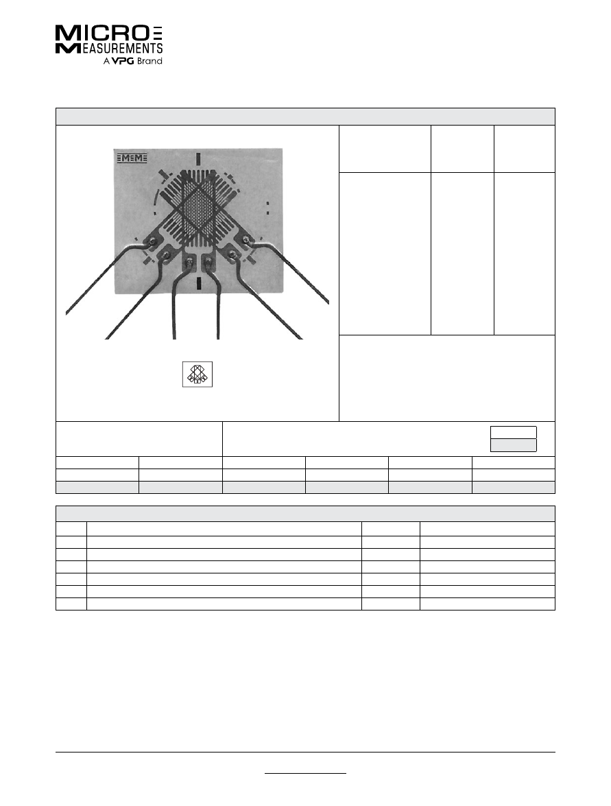
For technical questions, contact
mm@vpgsensors.com
Document No.: 11191
Revision: 17-Nov-2015
www.micro-measurements.com
93
120WR
General Purpose Strain Gages—Rectangular Rosette
General Purpose Strain Gages—Rectangular Rosette
GAGE PATTERN DATA
actual size
GAGE
DESIGNATION
See Note 1, 3
RESISTANCE
(OHMS)
See Note 2
OPTIONS
AVAILABLE
See Note 3
WA-XX-120WR-120
WA-XX-120WR-350
WD-DY-120WR-350
WK-XX-120WR-120
WK-XX-120WR-350
SA-XX-120WR-120
SA-XX-120WR-350
SK-XX-120WR-120
SK-XX-120WR-350
SD-DY-120WR-350
120 ± 0.5%
350 ± 0.5%
350 ± 0.5%
120 ± 0.5%
350 ± 0.5%
120 ± 0.5%
350 ± 0.5%
120 ± 0.5%
350 ± 0.5%
350 ± 0.5%
W
W
W*
W
W
DESCRIPTION
Three-element 45° rectangular stacked rosette
GAGE DIMENSIONS
Legend
ES = Each Section
CP = Complete Pattern
S = Section (S1 = Section 1)
M = Matrix
inch
millimeter
Gage Length
Overall Length
Grid Width
Overall Width
Matrix Length
Matrix Width
0.120 ES
0.34 M
0.080 ES
0.040 M
0.34
0.40
3.05 ES
8.6 M
2.03 ES
10.2 M
8.6
10.2
GAGE SERIES DATA
—
See Gage Series datasheet for complete specifications
Series
Description
Strain Range
Temperature Range
WA
Fully encapsulated constantan gages with high-endurance leadwires.
±2%
–100° to +400°F (–75° to +205°)
WD
Fully encapsulated isoelastic gages with high-endurance leadwires.
±1.5%
–320° to +500°F (–195° to +260°C)
WK
Fully encapsulated K-alloy gages with high-endurance leadwires.
±1.5%
–452° to +550°F (–269° to +290°C)
SA
Fully encapsulated constantan gages with solder dots.
±2%
–100° to +400°F (–75° to +205°C)
SK
Fully encapsulated K-alloy gages with solder dots.
±1.5%
–452° to +450°F (–269° to +230°C)
SD
Equivalent to WD Series, but with solder dots instead of leadwires.
±1.5%
–320° to +400°F (–195° to +205°C)
Note 1:
Insert desired S-T-C number in spaces marked XX.
Note 2:
Tolerance is increased when Option W, E, SE, LE, or P is specified.
Note 3:
Products with designations and options shown in
bold
are not RoHS compliant.
*Options available but not normally recommended. See Optional Features datasheet for details.
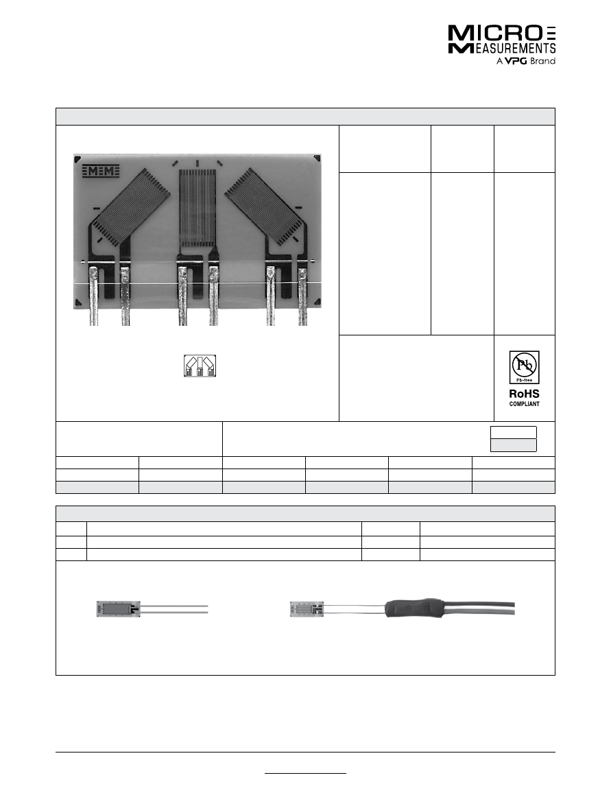
For technical questions, contact
mm@vpgsensors.com
www.micro-measurements.com
94
Document No.: 11198
Revision: 17-Nov-2015
125LR
General Purpose Strain Gages—Rectangular Rosette
General Purpose Strain Gages—Rectangular Rosette
GAGE PATTERN DATA
actual size
GAGE
DESIGNATION
See Note 1
RESISTANCE
(OHMS)
OPTIONS
AVAILABLE
L2A-XX-125LR-120
L2A-XX-125LR-350
C2A-XX-125LR-120
C2A-XX-125LR-350
120 ± 0.6%
350 ± 0.6%
120 ± 0.6%
350 ± 0.6%
DESCRIPTION
General-purpose 45° rectangular
single-plane rosette.
GAGE DIMENSIONS
Legend
ES = Each Section
CP = Complete Pattern
S = Section (S1 = Section 1)
M = Matrix
inch
millimeter
Gage Length
Overall Length
Grid Width
Overall Width
Matrix Length
Matrix Width
0.125
0.245
0.070
0.415
0.290
0.475
3.18
6.22
1.78
10.54
7.37
12.06
GAGE SERIES DATA
—
See Gage Series datasheet for complete specifications
Series
Description
Strain Range
Temperature Range
L2A
Encapsulated constantan gages with preattached ribbon leads.
±3%
–100° to +250°F (–75° to +120°C)
C2A
Encapsulated constantan gages with preattached ready-to-use cables.
±3%
–60° to +180°F (–50° to +80°C)
Example of an
L2A Construction
Example of an
C2A Construction
Note 1:
Insert desired S-T-C number in spaces marked XX.
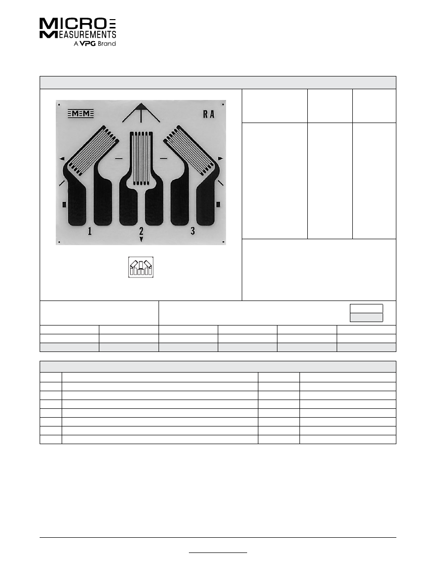
For technical questions, contact
mm@vpgsensors.com
Document No.: 11208
Revision: 05-Jan-2016
www.micro-measurements.com
95
125RA
General Purpose Strain Gages—Rectangular Rosette
General Purpose Strain Gages—Rectangular Rosette
GAGE PATTERN DATA
actual size
GAGE
DESIGNATION
See Note 1, 3
RESISTANCE
(OHMS)
See Note 2
OPTIONS
AVAILABLE
See Note 3
EA-XX-125RA-120
EK-XX-125RA-350*
WA-XX-125RA-120
WK-XX-125RA-350
EP-08-125RA-120
SA-XX-125RA-120
SK-XX-125RA-350
120 ± 0.2%
350 ± 0.2%
120 ± 0.4%
350 ± 0.4%
120 ± 0.2%
120 ± 0.4%
350 ± 0.4%
W, E, L, LE
W,
SE
W**
W**
DESCRIPTION
General-purpose three-element 45° rectangular
rosette. Compact geometry. See also 125RD and
125UR patterns.
GAGE DIMENSIONS
Legend
ES = Each Section
CP = Complete Pattern
S = Section (S1 = Section 1)
M = Matrix
inch
millimeter
Gage Length
Overall Length
Grid Width
Overall Width
Matrix Length
Matrix Width
0.125 ES
0.275 CP
0.062 ES
0.424 CP
0.39
0.46
3.18 ES
6.99 CP
1.57 ES
10.77 CP
9.9
11.7
GAGE SERIES DATA
—
See Gage Series datasheet for complete specifications
Series
Description
Strain Range
Temperature Range
EA
Constantan foil in combination with a tough, flexible, polyimide backing.
±3%
–100° to +350°F (–75° to +175°C)
EK
K-alloy foil in combination with a tough, flexible polyimide backing.
±1.5%
–320° to +350°F (–195° to +175°C)
WA
Fully encapsulated constantan gages with high-endurance leadwires.
±2%
–100° to +400°F (–75° to +205°)
WK
Fully encapsulated K-alloy gages with high-endurance leadwires.
±1.5%
–452° to +550°F (–269° to +290°C)
EP
Annealed constantan foil with tough, high-elongation polyimide backing.
±20%
–100° to +400°F (–75° to +205°C)
SA
Fully encapsulated constantan gages with solder dots.
±2%
–100° to +400°F (–75° to +205°C)
SK
Fully encapsulated K-alloy gages with solder dots.
±1.5%
–452° to +450°F (–269° to +230°C)
Note 1:
Insert desired S-T-C number in spaces marked XX.
Note 2:
Tolerance is increased when Option W, E, SE, LE, or P is specified.
Note 3:
Products with designations and options shown in
bold
are not RoHS compliant.
* EK-Series gages are supplied with duplex copper pads (DP) when optional feature W or SE is not specified.
** Options available but not normally recommended. See Optional Features datasheet for details.
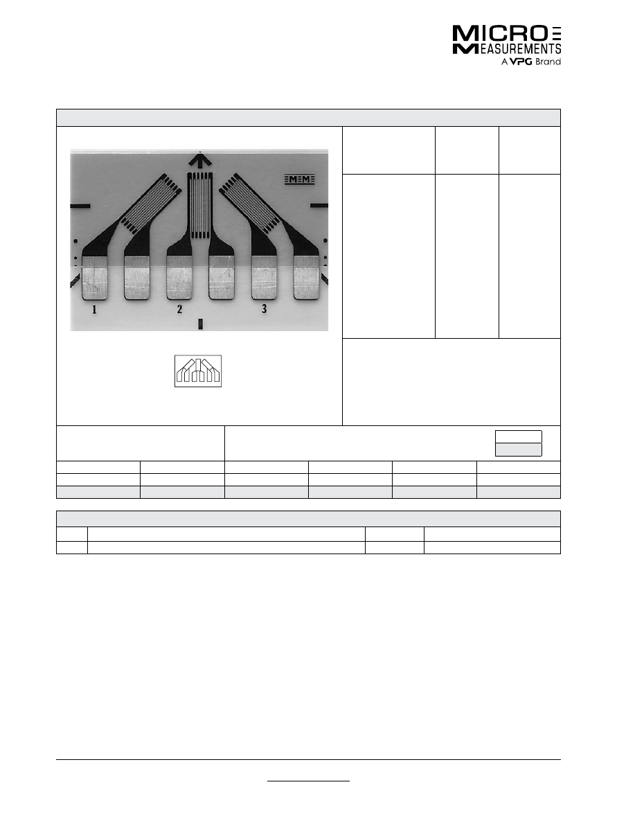
For technical questions, contact
mm@vpgsensors.com
www.micro-measurements.com
96
Document No.: 11225
Revision: 26-Aug-2015
125UR
General Purpose Strain Gages—Rectangular Rosette
General Purpose Strain Gages—Rectangular Rosette
GAGE PATTERN DATA
actual size
GAGE
DESIGNATION
See Note 1
RESISTANCE
(OHMS)
OPTIONS
AVAILABLE
See Note 2
CEA-XX-125UR-120
CEA-XX-125UR-350
120 ± 0.4%
350 ± 0.4%
P2
P2
DESCRIPTION
General-purpose 45° single-plane rosette. Compact
geometry. Exposed solder tab area 0.08 x 0.06 in
(2.0 x 1.5 mm).
GAGE DIMENSIONS
Legend
ES = Each Section
CP = Complete Pattern
S = Section (S1 = Section 1)
M = Matrix
inch
millimeter
Gage Length
Overall Length
Grid Width
Overall Width
Matrix Length
Matrix Width
0.125 ES
0.300 CP
0.060 ES
0.560 CP
0.42
0.62
3.18 ES
7.62 CP
1.52 ES
14.22 CP
10.7
15.7
GAGE SERIES DATA
—
See Gage Series datasheet for complete specifications
Series
Description
Strain Range
Temperature Range
CEA
Universal general-purpose strain gages.
±5%
–100° to +350°F (–75° to +175°C)
Note 1:
Insert desired S-T-C number in spaces marked XX.
Note 2:
Products with designations and options shown in bold are not RoHS compliant.

For technical questions, contact
mm@vpgsensors.com
Document No.: 11249
Revision: 17-Nov-2015
www.micro-measurements.com
97
125WW
General Purpose Strain Gages—Stacked Rosette
General Purpose Strain Gages—Stacked Rosette
GAGE PATTERN DATA
actual size
C2A
version
shown
GAGE
DESIGNATION
See Note 1
RESISTANCE
(OHMS)
OPTIONS
AVAILABLE
L2A-XX-125WW-120
L2A-XX-125WW-350
C2A-XX-125WW-120
C2A-XX-125WW-350
120 ± 0.6%
350 ± 0.6%
120 ± 0.6%
350 ± 0.6%
DESCRIPTION
Stacked, 0°-45°-90° rosette for use in
applications involving limited gaging
areas or steep strain gradients.
GAGE DIMENSIONS
Legend
ES = Each Section
CP = Complete Pattern
S = Section (S1 = Section 1)
M = Matrix
inch
millimeter
Gage Length
Overall Length
Grid Width
Overall Width
Matrix Length
Matrix Width
0.125 ES
0.241 CP
0.070 ES
0.280 CP
0.309
0.375
3.18 ES
6.12 CP
1.78 ES
7.11 CP
7.85
9.53
GAGE SERIES DATA
—
See Gage Series datasheet for complete specifications
Series
Description
Strain Range
Temperature Range
L2A
Encapsulated constantan gages with preattached ribbon leads.
±3%
–100° to +150°F (–75° to +65°C)
C2A
Encapsulated constantan gages with preattached ready-to-use cables.
±3%
–60° to +150°F (–50° to +65°C)
Example of an
L2A Construction
Example of an
C2A Construction
Note 1:
Insert desired S-T-C number in spaces marked XX.
Note 2:
Upper use range is reduced to these values for stacked patterns.
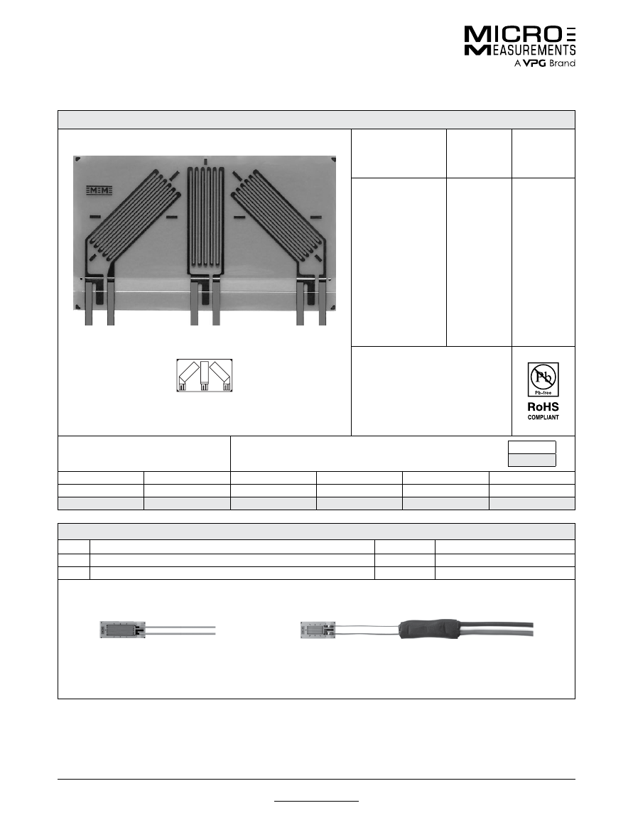
For technical questions, contact
mm@vpgsensors.com
www.micro-measurements.com
98
Document No.: 11296
Revision: 17-Nov-2015
250LR
General Purpose Strain Gages—Rectangular Rosette
General Purpose Strain Gages—Rectangular Rosette
GAGE PATTERN DATA
actual size
GAGE
DESIGNATION
See Note 1
RESISTANCE
(OHMS)
OPTIONS
AVAILABLE
L2A-XX-250LR-120
L2A-XX-250LR-350
C2A-XX-250LR-120
C2A-XX-250LR-350
120 ± 0.6%
350 ± 0.6%
120 ± 0.6%
350 ± 0.6%
DESCRIPTION
General-purpose 45° rectangular
single-plane rosette.
GAGE DIMENSIONS
Legend
ES = Each Section
CP = Complete Pattern
S = Section (S1 = Section 1)
M = Matrix
inch
millimeter
Gage Length
Overall Length
Grid Width
Overall Width
Matrix Length
Matrix Width
0.250
0.373
0.100
0.655
0.420
0.715
6.35
9.47
2.54
16.64
10.67
18.16
GAGE SERIES DATA
—
See Gage Series datasheet for complete specifications
Series
Description
Strain Range
Temperature Range
L2A
Encapsulated constantan gages with preattached ribbon leads.
±3%
–100° to +250°F (–75° to +120°C)
C2A
Encapsulated constantan gages with preattached ready-to-use cables.
±3%
–60° to +180°F (–50° to +80°C)
Example of an
L2A Construction
Example of an
C2A Construction
Note 1:
Insert desired S-T-C number in spaces marked XX.
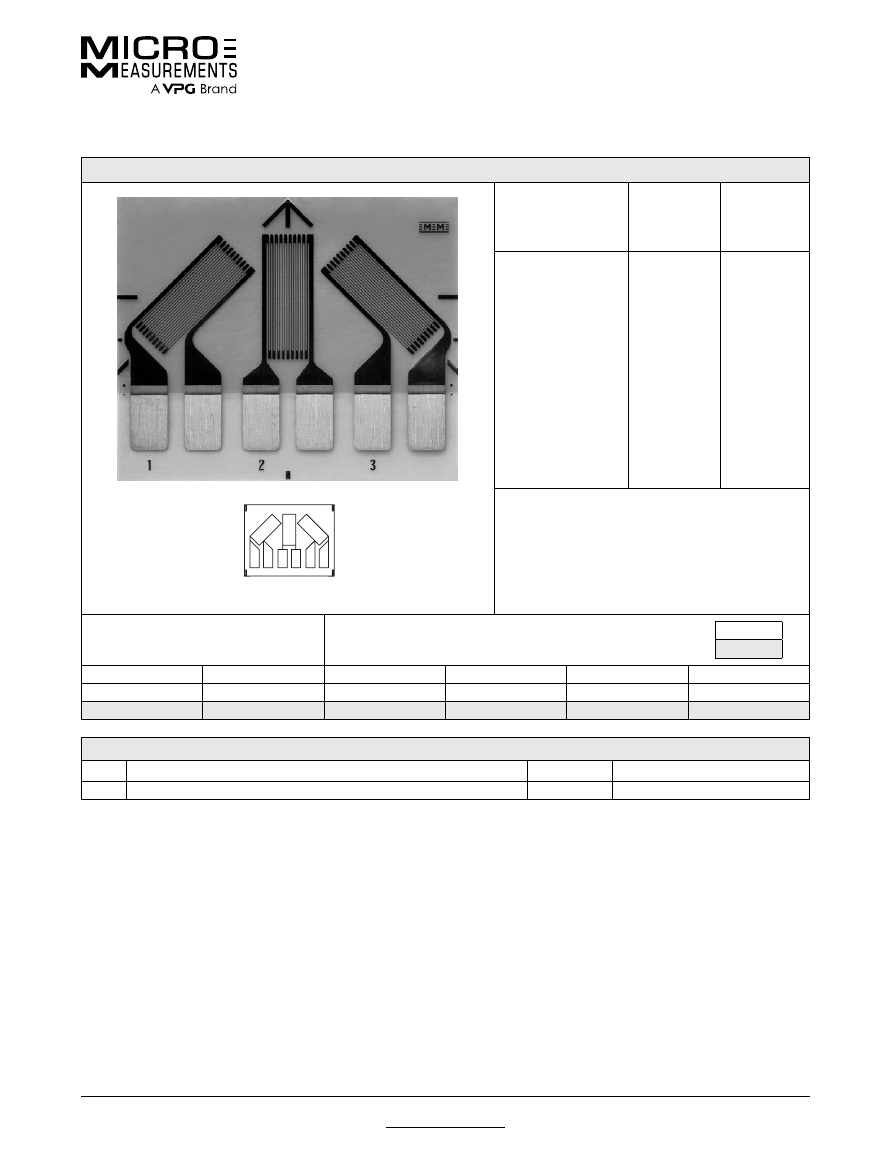
For technical questions, contact
mm@vpgsensors.com
Document No.: 11299
Revision: 17-Nov-2015
www.micro-measurements.com
99
250UR
General Purpose Strain Gages—Rectangular Rosette
General Purpose Strain Gages—Rectangular Rosette
GAGE PATTERN DATA
actual size
GAGE
DESIGNATION
See Note 1
RESISTANCE
(OHMS)
OPTIONS
AVAILABLE
See Note 2
CEA-XX-250UR-120
CEA-XX-250UR-350
120 ± 0.4%
350 ± 0.4%
P2
P2
DESCRIPTION
Large three-element 45° single-plane rosette. Exposed
solder tab area 0.13 x 0.08 in [3.3 x 2.0 mm].
GAGE DIMENSIONS
Legend
ES = Each Section
CP = Complete Pattern
S = Section (S1 = Section 1)
M = Matrix
inch
millimeter
Gage Length
Overall Length
Grid Width
Overall Width
Matrix Length
Matrix Width
0.250 ES
0.500 CP
0.120 ES
0.760 CP
0.65
0.80
6.35 ES
12.70 CP
3.05 ES
19.30 CP
16.5
20.3
GAGE SERIES DATA
—
See Gage Series datasheet for complete specifications
Series
Description
Strain Range
Temperature Range
CEA
Universal general-purpose strain gages.
±5%
–100° to +350°F (–75° to +175°C)
Note 1:
Insert desired S-T-C number in spaces marked XX.
Note 2:
Products with designations and options shown in bold are not RoHS compliant.
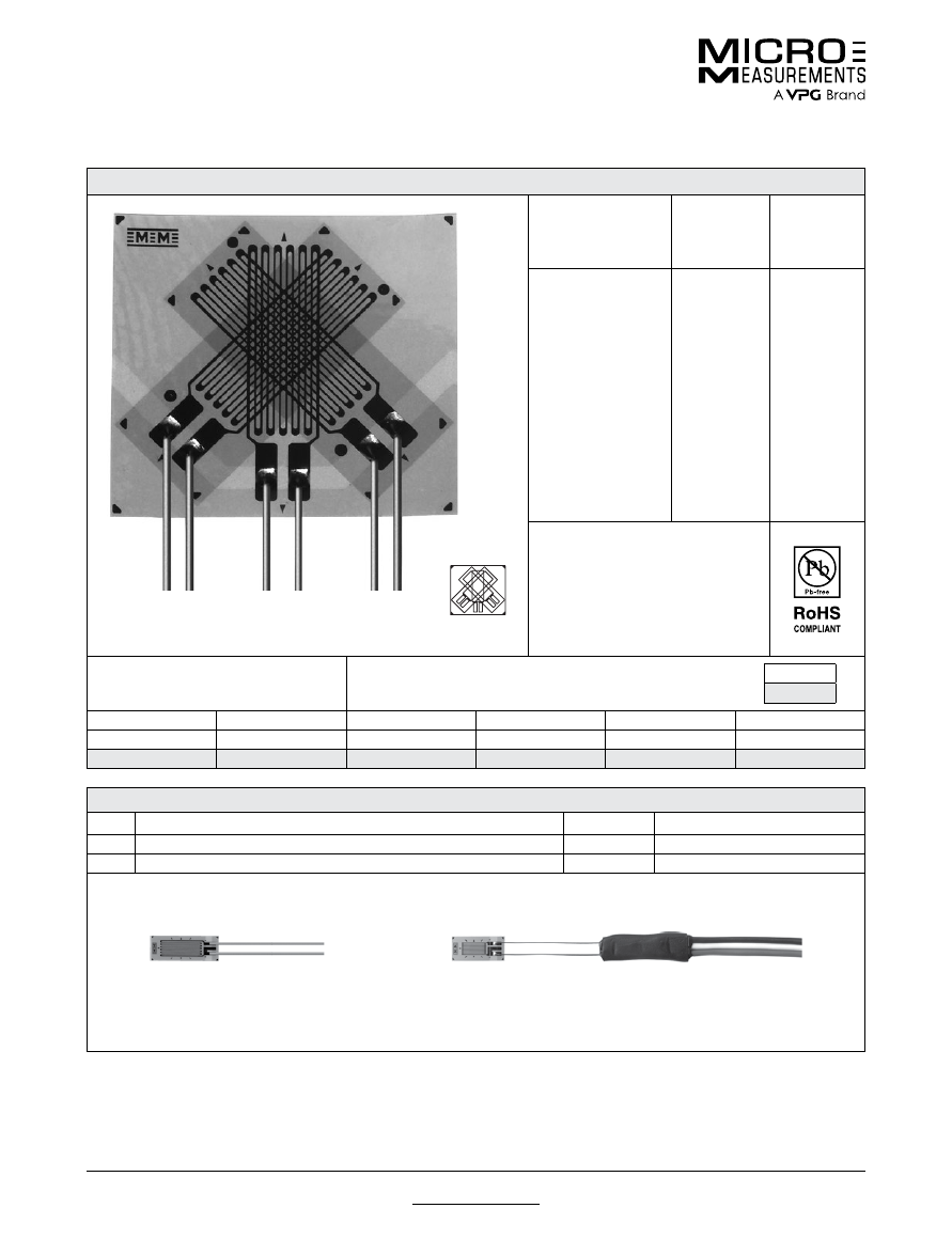
For technical questions, contact
mm@vpgsensors.com
www.micro-measurements.com
100
Document No.: 11248
Revision: 17-Nov-2015
250WW
General Purpose Strain Gages—Stacked Rosette
General Purpose Strain Gages—Stacked Rosette
GAGE PATTERN DATA
actual size
GAGE
DESIGNATION
See Note 1
RESISTANCE
(OHMS)
OPTIONS
AVAILABLE
L2A-XX-250WW-120
L2A-XX-250WW-350
C2A-XX-250WW-120
C2A-XX-250WW-350
120 ± 0.6%
350 ± 0.6%
120 ± 0.6%
350 ± 0.6%
DESCRIPTION
Stacked, 0°-45°-90° rosette for use in
applications involving limited gaging
areas or steep strain gradients.
GAGE DIMENSIONS
Legend
ES = Each Section
CP = Complete Pattern
S = Section (S1 = Section 1)
M = Matrix
inch
millimeter
Gage Length
Overall Length
Grid Width
Overall Width
Matrix Length
Matrix Width
0.250 ES
0.362 CP
0.100 ES
0.375 CP
0.418
0.477
6.35 ES
9.19 CP
2.54 ES
9.53 CP
10.62
12.12
GAGE SERIES DATA
—
See Gage Series datasheet for complete specifications
Series
Description
Strain Range
Temperature Range
L2A
Encapsulated constantan gages with preattached ribbon leads.
±3%
–100° to +150°F (–75° to +65°C)
C2A
Encapsulated constantan gages with preattached ready-to-use cables.
±3%
–60° to +150°F (–50° to +65°C)
Example of an
L2A Construction
Example of an
C2A Construction
Note 1:
Insert desired S-T-C number in spaces marked XX.
Note 2:
Upper use range is reduced to these values for stacked patterns.
For technical questions, contact
mm@vpgsensors.com
Document No.: 11323
Revision: 17-Nov-2015
www.micro-measurements.com
101
Other Rectangular Rosette Patterns
General Purpose Strain Gages
General Purpose Strain Gages
GAGE PATTERN
GAGE SERIES
See Note 1
GAGE RESISTANCE
(OHMS)
GAGE LENGTH
inches
millimeters
015RC
actual size
EA,
SA
120
0.015
0.38
Micro-miniature three-element 45° rosette with one tab common to all sections.
See also 015RJ pattern. Note: See Strip Patterns datasheet for discussion of
common-tab gages.
Matrix size: 0.18L x 0.23W in. (4.6L x 5.8W mm)
015RJ
actual size
EA,
SA
120
0.015
0.38
Micro-miniature three-element 45° rosette. Similar to 015RC pattern except
each section has separate tabs for electrical isolation.
Matrix size: 0.19L x 0.23W in. (4.8L x 5.8W mm)
030WR
actual size
WA
, WK,
SA, SK
120
0.03
0.76
Miniature three-element 45° rectangular stacked rosette.
Matrix size: 0.18L x 0.19W in. (4.6L x 4.8W mm)
031RB
actual size
EA, EP,
SA
120
0.031
0.79
Miniature 45° rectangular single-plane rosette with compact geometry.
Matrix size: 0.19L x 0.24W in. (4.8L x 6.1W mm)
062RB
actual size
EA,
WA
, WK, EP,
SA, SK
120, 350
0.062
1.57
Small 45° rectangular single-plane rosette with compact geometry.
Matrix size: 0.42L x 0.46W in. (10.7L x 11.7W mm)
062RF
actual size
EA,
SA
350
0.062
1.57
Small 45° rectangular single-plane rosette designed for use with Option W.
Matrix size: 0.25L x 0.46W in. (6.4L x 11.7W mm)
Note 1:
Products with designations and options shown in
bold
are not RoHS compliant.
See http://www.vishaypg.com/micro-measurements/stress-analysis-strain-gages/other-rectangular-rosettes/
for complete
specifications.
For technical questions, contact
mm@vpgsensors.com
www.micro-measurements.com
102
Document No.: 11323
Revision: 17-Nov-2015
Other Rectangular Rosette Patterns
General Purpose Strain Gages
GAGE PATTERN
GAGE SERIES
See Note 1
GAGE RESISTANCE
(OHMS)
GAGE LENGTH
inches
millimeters
120WR
actual size
WA
, WD, WK,
SA, SK,
SD
120, 350
0.12
3.05
Three-element 45° rectangular stacked rosette.
Matrix size: 0.34L x 0.40W in. (8.6L x 10.2W mm)
125RD
actual size
EA,
WA
,
SA
350
0.125
3.18
General-purpose three-element 45° rectangular rosette. Similar to 125RA
pattern except for grid resistance.
Matrix size: 0.40L x 0.47W in. (10.1L x 11.9W mm)
250RA
actual size
EA,
WA
, WK, EP,
SA, SK
120, 350
0.25
6.35
Large three-element 45° rectangular rosette with convenient solder tab
arrangement. See also 250RD pattern.
Matrix size: 0.78L x 0.93W in. (19.8L x 23.6W mm)
250RD
actual size
EA, EK,
S2K, WA,
WK,
EP,
SA, SK
350, 1000
0.25
6.35
Large three-element 45° rectangular rosette. Similar to the 250RA pattern
except for resistance. EK-Series gages are supplied with duplex copper pads
(DP) when optional feature W or SE is not specified.
Matrix size: 0.78L x 0.93W in. (19.8L x 23.6W mm)
250WR
actual size
WA
, WD, WK,
SA, SK,
SD
120, 350
0.25
6.35
Three-element 45° rectangular stacked rosette.
Matrix size: 0.51L x 0.60W in. (13.0L x 15.2W mm)
Note 1:
Products with designations and options shown in
bold
are not RoHS compliant.
See http://www.vishaypg.com/micro-measurements/stress-analysis-strain-gages/other-rectangular-rosettes/
for complete
specifications.
For technical questions, contact
mm@vpgsensors.com
www.micro-measurements.com
103
Delta Rosettes
(General-Use)
FEATURES
• Gage patterns designed for determining principle stresses
and strains
• All patterns have three grids oriented at 0°, 60° and
120° angles
• Both stacked and planar constructions available
• Gage lengths from 0.30” (0.76 mm) to 0.125” (3.18 mm)
PATTERNS
Other Delta Rosettes .......................... 104
For technical questions, contact
mm@vpgsensors.com
www.micro-measurements.com
104
Document No.: 11325
Revision: 31-Aug-2015
Other Delta Rosette Patterns
General Purpose Strain Gages
General Purpose Strain Gages
GAGE PATTERN
GAGE SERIES
See Note 1
GAGE RESISTANCE
(OHMS)
GAGE LENGTH
inches
millimeters
030YB
actual size
EA,
SA
120
0.03
0.76
Miniature three-element 60° delta single-plane rosette.
Matrix size: 0.21L x 0.27W in. (5.3L x 6.9W mm)
060WY
actual size
WA
, WK,
SA, SK
120, 350, 1000
0.06
1.52
Small three-element 60° delta stacked rosette.
Matrix size: 0.24L x 0.30W in. (6.1L x 7.6W mm)
125UY
actual size
CEA
120, 350
0.125
3.18
Three-element 60° delta single-plane rosette.
Matrix size: 0.50L x 0.44W in. (12.7L x 11.2W mm)
Note 1:
Products with designations and options shown in
bold
are not RoHS compliant.
See http://www.micro-measurements.com/stress-analysis-strain-gages/delta-rosettes/
for complete specifications.

For technical questions, contact
mm@vpgsensors.com
www.micro-measurements.com
105
Shear/Torque
Rosettes
(General-Use)
FEATURES
• Gage patterns designed for measuring shear strain and torque
• Individual and multiple grid patterns
• Gage lengths from 0.062” (1.57 mm) to 0.250” (6.35 mm)
PATTERNS
062DY ................................................ 106
062LV .................................................. 107
062TH ................................................. 108
062TV ................................................. 109
062UV ................................................ 110
125TK ................................................. 111
187UV ................................................ 112
250US ................................................ 113
Other Shear/Torque Patterns ............. 114
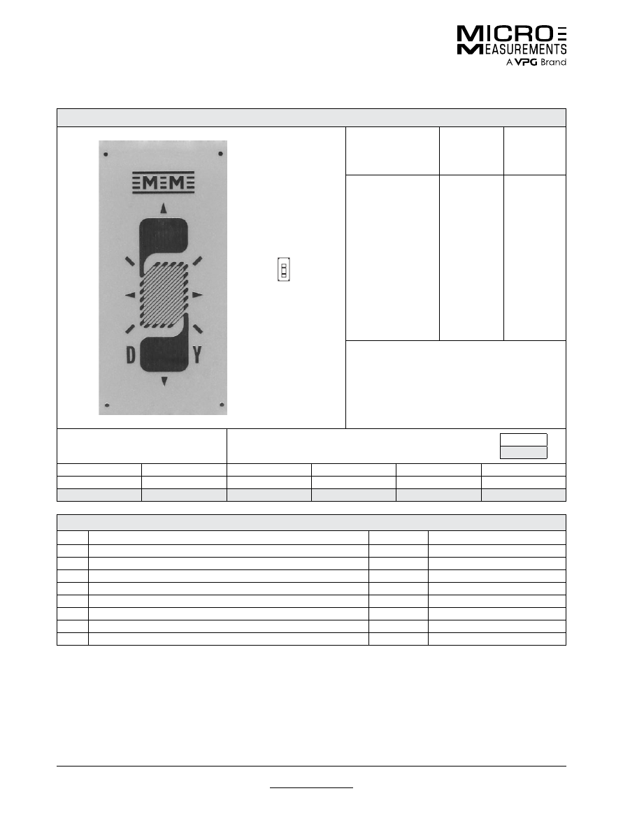
For technical questions, contact
mm@vpgsensors.com
www.micro-measurements.com
106
Document No.: 11328
Revision: 15-Nov-2015
062DY
General Purpose Strain Gages—Shear/ Torque Pattern
General Purpose Strain Gages—Shear/ Torque Pattern
GAGE PATTERN DATA
actual size
GAGE
DESIGNATION
See Note 1, 3
RESISTANCE
(OHMS)
See Note 2
OPTIONS
AVAILABLE
See Note 3
EA-XX-062DY-120
ED-DY-062DY-350
WA-XX-062DY-120
WK-XX-062DY-350
SA-XX-062DY-350
SK-XX-062DY-350
SD-DY-062DY-350
WD-DY-062DY-350
120 ± 0.15%
350 ± 0.4%
120 ± 0.3%
350 ± 0.3%
120 ± 0.3%
350 ± 0.3%
350 ± 0.8%
350 ± 0.8%
E, L, LE
E, L*, LE*
DESCRIPTION
45° torque gage. Similar to 062DW pattern but with
opposite grid angle.
GAGE DIMENSIONS
Legend
ES = Each Section
CP = Complete Pattern
S = Section (S1 = Section 1)
M = Matrix
inch
millimeter
Gage Length
Overall Length
Grid Width
Overall Width
Matrix Length
Matrix Width
0.062
0.175
0.055
0.055
0.30
0.15
1.57
4.45
1.40
1.40
7.6
3.8
GAGE SERIES DATA
—
See Gage Series datasheet for complete specifications
Series
Description
Strain Range
Temperature Range
EA
Constantan foil in combination with a tough, flexible, polyimide backing.
±3%
–100° to +350°F (–75° to +175°C)
ED
Isoelastic foil in combination with tough, flexible polyimide film.
±2%
–320° to +400°F (–195° to +205°C)
WA
Fully encapsulated constantan gages with high-endurance leadwires.
±2%
–100° to +400°F (–75° to +205°)
WK
Fully encapsulated K-alloy gages with high-endurance leadwires.
±1.5%
–452° to +550°F (–269° to +290°C)
SA
Fully encapsulated constantan gages with solder dots.
±2%
–100° to +400°F (–75° to +205°C)
SK
Fully encapsulated K-alloy gages with solder dots.
±1.5%
–452° to +450°F (–269° to +230°C)
SD
Equivalent to WD Series, but with solder dots instead of leadwires.
±1.5%
–320° to +400°F (–195° to +205°C)
WD
Fully encapsulated isoelastic gages with high-endurance leadwires.
±1.5%
–320° to +500°F (–195° to +260°C)
Note 1:
Insert desired S-T-C number in spaces marked XX.
Note 2:
Tolerance is increased when Option W, E, SE, LE, or P is specified.
Note 3:
Products with designations and options shown in
bold
are not RoHS compliant.
*Options available but not normally recommended. See Optional Features datasheet for details.
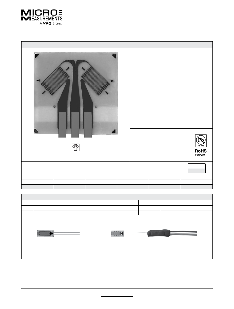
For technical questions, contact
mm@vpgsensors.com
Document No.: 11097
Revision: 27-Mar-2015
www.micro-measurements.com
107
062LV
General Purpose Strain Gages—Shear/ Torque Pattern
General Purpose Strain Gages—Shear/ Torque Pattern
GAGE PATTERN DATA
actual size
GAGE
DESIGNATION
See Note 1
RESISTANCE
(OHMS)
OPTIONS
AVAILABLE
L2A-XX-062LV-120
C2A-XX-062LV-120
120 ± 0.6%
120 ± 0.6%
DESCRIPTION
Two-element 90° torque gage.
GAGE DIMENSIONS
Legend
ES = Each Section
CP = Complete Pattern
S = Section (S1 = Section 1)
M = Matrix
inch
millimeter
Gage Length
Overall Length
Grid Width
Overall Width
Matrix Length
Matrix Width
0.062 ES
0.214 CP
0.050 ES
0.215 CP
0.255
0.265
1.52 ES
5.44 CP
1.27 ES
5.46 CP
6.48
6.73
GAGE SERIES DATA
—
See Gage Series datasheet for complete specifications
Series
Description
Strain Range
Temperature Range
L2A
Encapsulated constantan gages with preattached ribbon leads.
±3%
–100° to +250°F (–75° to +120°C)
C2A
Encapsulated constantan gages with preattached ready-to-use cables.
±3%
–60° to +180°F (–50° to +80°C)
Example of an
L2A Construction
Example of an
C2A Construction
Note 1:
Insert desired S-T-C number in spaces marked XX.
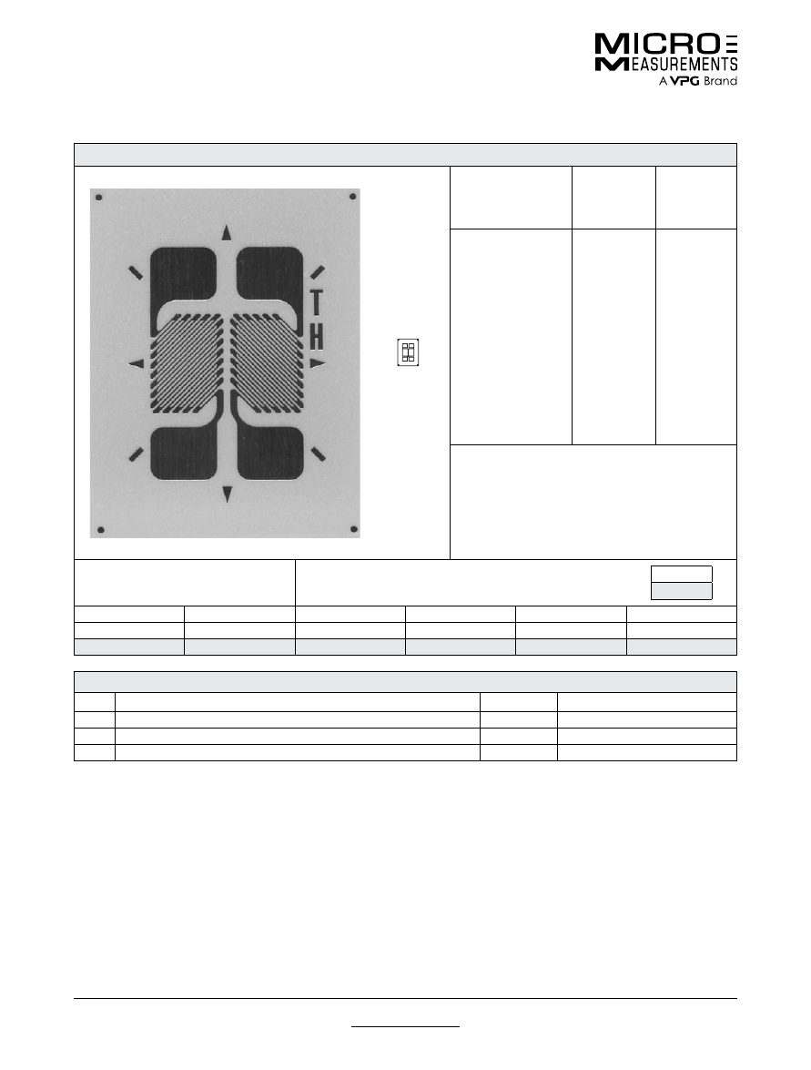
For technical questions, contact
mm@vpgsensors.com
www.micro-measurements.com
108
Document No.: 11330
Revision: 15-Nov-2015
062TH
General Purpose Strain Gages—Shear/ Torque Pattern
General Purpose Strain Gages—Shear/ Torque Pattern
GAGE PATTERN DATA
actual size
GAGE
DESIGNATION
See Note 1, 3
RESISTANCE
(OHMS)
See Note 2
OPTIONS
AVAILABLE
See Note 3
EA-XX-062TH-120
SA-XX-062TH-120
SK-XX-062TH-350
120 ± 0.2%
120 ± 0.4%
350 ± 0.4%
E, L, LE
DESCRIPTION
Two-element 90° torque gage. Sections are electrically
independent. See also 062TV and 062TW patterns.
GAGE DIMENSIONS
Legend
ES = Each Section
CP = Complete Pattern
S = Section (S1 = Section 1)
M = Matrix
inch
millimeter
Gage Length
Overall Length
Grid Width
Overall Width
Matrix Length
Matrix Width
0.062 ES
0.175 CP
0.055 ES
0.115 CP
0.27
0.21
1.57 ES
4.45 CP
1.40 ES
2.92 CP
6.9
5.3
GAGE SERIES DATA
—
See Gage Series datasheet for complete specifications
Series
Description
Strain Range
Temperature Range
EA
Constantan foil in combination with a tough, flexible, polyimide backing.
±3%
–100° to +350°F (–75° to +175°C)
SA
Fully encapsulated constantan gages with solder dots.
±2%
–100° to +400°F (–75° to +205°C)
SK
Fully encapsulated K-alloy gages with solder dots.
±1.5%
–452° to +450°F (–269° to +230°C)
Note 1:
Insert desired S-T-C number in spaces marked XX.
Note 2:
Tolerance is increased when Option W, E, SE, LE, or P is specified.
Note 3:
Products with designations and options shown in
bold
are not RoHS compliant.
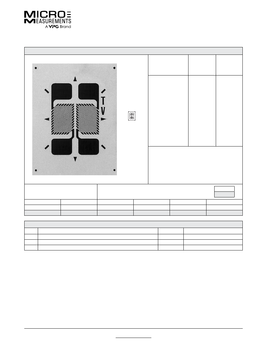
For technical questions, contact
mm@vpgsensors.com
Document No.: 11122
Revision: 15-Nov-2015
www.micro-measurements.com
109
062TV
General Purpose Strain Gages—Shear/ Torque Pattern
General Purpose Strain Gages—Shear/ Torque Pattern
GAGE PATTERN DATA
actual size
GAGE
DESIGNATION
See Note 1, 3
RESISTANCE
(OHMS)
See Note 2
OPTIONS
AVAILABLE
See Note 3
EA-XX-062TV-350
SA-XX-062TV-350
SK-XX-062TV-500
350 ± 0.2%
350 ± 0.4%
500 ± 0.4%
E, L, LE
DESCRIPTION
Two-element 90° torque gage.
GAGE DIMENSIONS
Legend
ES = Each Section
CP = Complete Pattern
S = Section (S1 = Section 1)
M = Matrix
inch
millimeter
Gage Length
Overall Length
Grid Width
Overall Width
Matrix Length
Matrix Width
0.062 ES
0.175 CP
0.055 ES
0.115 CP
0.27
0.21
1.57 ES
4.45 CP
1.40 ES
2.92 CP
6.9
5.3
GAGE SERIES DATA
—
See Gage Series datasheet for complete specifications
Series
Description
Strain Range
Temperature Range
EA
Constantan foil in combination with a tough, flexible, polyimide backing.
±3%
–100° to +350°F (–75° to +175°C)
SA
Fully encapsulated constantan gages with solder dots.
±2%
–100° to +400°F (–75° to +205°C)
SK
Fully encapsulated K-alloy gages with solder dots.
±1.5%
–452° to +450°F (–269° to +230°C)
Note 1:
Insert desired S-T-C number in spaces marked XX.
Note 2:
Tolerance is increased when Option W, E, SE, LE, or P is specified.
Note 3:
Products with designations and options shown in
bold
are not RoHS compliant.
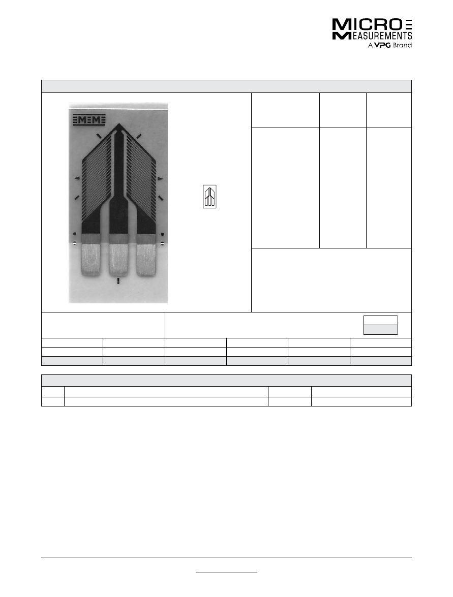
For technical questions, contact
mm@vpgsensors.com
www.micro-measurements.com
110
Document No.: 11126
Revision: 15-Nov-2015
062UV
General Purpose Strain Gages—Shear/ Torque Pattern
General Purpose Strain Gages—Shear/ Torque Pattern
GAGE PATTERN DATA
actual size
GAGE
DESIGNATION
See Note 1
RESISTANCE
(OHMS)
OPTIONS
AVAILABLE
See Note 2
CEA-XX-062UV-350
CEA-XX-062UV-500
350 ± 0.4%
500 ± 0.4%
P2
DESCRIPTION
Two-element 90° rosette for torque and shear-strain
measurement. Sections have a common electrical
connection. Exposed solder tab area is 0.04 x 0.07 in
[1.0 x 1.8 mm].
GAGE DIMENSIONS
Legend
ES = Each Section
CP = Complete Pattern
S = Section (S1 = Section 1)
M = Matrix
inch
millimeter
Gage Length
Overall Length
Grid Width
Overall Width
Matrix Length
Matrix Width
0.062 ES
0.330 CP
0.063 ES
0.160 CP
0.42
0.23
1.57 ES
8.38 CP
1.60 ES
4.06 CP
10.7
5.8
GAGE SERIES DATA
—
See Gage Series datasheet for complete specifications
Series
Description
Strain Range
Temperature Range
CEA
Universal general-purpose strain gages.
±3%
–100° to +350°F (–75° to +175°C)
Note 1:
Insert desired S-T-C number in spaces marked XX.
Note 2:
Products with designations and options shown in bold are not RoHS compliant.
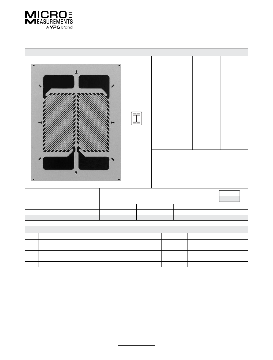
For technical questions, contact
mm@vpgsensors.com
Document No.: 11210
Revision: 15-Nov-2015
www.micro-measurements.com
111
125TK
General Purpose Strain Gages—Shear/ Torque Pattern
General Purpose Strain Gages—Shear/ Torque Pattern
GAGE PATTERN DATA
actual size
GAGE
DESIGNATION
See Note 1, 3
RESISTANCE
(OHMS)
See Note 2
OPTIONS
AVAILABLE
See Note 3
EA-XX-125TK-350
WA-XX-125TK-350
WK-XX-125TK-10C
SA-XX-125TK-350
SK-XX-125TK-10C
350 ± 0.2%
350 ± 0.4%
1000 ± 0.4%
350 ± 0.4%
1000 ± 0.4%
E, L, LE
DESCRIPTION
High-resistance two-element 90° torque gage. Similar
to 125TL pattern except sections are electrically
independent. See also 125TH pattern.
GAGE DIMENSIONS
Legend
ES = Each Section
CP = Complete Pattern
S = Section (S1 = Section 1)
M = Matrix
inch
millimeter
Gage Length
Overall Length
Grid Width
Overall Width
Matrix Length
Matrix Width
0.125 ES
0.320 CP
0.110 ES
0.225 CP
0.40
0.31
3.18 ES
8.13 CP
2.79 ES
5.72 CP
10.2
7.9
GAGE SERIES DATA
—
See Gage Series datasheet for complete specifications
Series
Description
Strain Range
Temperature Range
EA
Constantan foil in combination with a tough, flexible, polyimide backing.
±5%
–100° to +350°F (–75° to +175°C)
WA
Fully encapsulated constantan gages with high-endurance leadwires.
±2%
–100° to +400°F (–75° to +205°)
WK
Fully encapsulated K-alloy gages with high-endurance leadwires.
±1.5%
–452° to +550°F (–269° to +290°C)
SA
Fully encapsulated constantan gages with solder dots.
±2%
–100° to +400°F (–75° to +205°C)
SK
Fully encapsulated K-alloy gages with solder dots.
±1.5%
–452° to +450°F (–269° to +230°C)
Note 1:
Insert desired S-T-C number in spaces marked XX.
Note 2:
Tolerance is increased when Option W, E, SE, LE, or P is specified.
Note 3:
Products with designations and options shown in
bold
are not RoHS compliant.

For technical questions, contact
mm@vpgsensors.com
www.micro-measurements.com
112
Document No.: 11244
Revision: 15-Nov-2015
187UV
General Purpose Strain Gages—Shear/ Torque Pattern
General Purpose Strain Gages—Shear/ Torque Pattern
GAGE PATTERN DATA
actual size
GAGE
DESIGNATION
See Note 1
RESISTANCE
(OHMS)
OPTIONS
AVAILABLE
See Note 2
CEA-XX-187UV-120
CEA-XX-187UV-350
120 ± 0.4%
350 ± 0.4%
P2
P2
DESCRIPTION
Two-element 90° rosette for torque and shear-strain
measurement. Sections have a common electrical
connection. Exposed solder tab area is 0.13 x 0.08 in
[3.3 x 2.0 mm].
GAGE DIMENSIONS
Legend
ES = Each Section
CP = Complete Pattern
S = Section (S1 = Section 1)
M = Matrix
inch
millimeter
Gage Length
Overall Length
Grid Width
Overall Width
Matrix Length
Matrix Width
0.187 ES
0.560 CP
0.150 ES
0.320 CP
0.63
0.39
4.75 ES
14.22 CP
3.81 ES
8.13 CP
15.9
9.8
GAGE SERIES DATA
—
See Gage Series datasheet for complete specifications
Series
Description
Strain Range
Temperature Range
CEA
Universal general-purpose strain gages.
±5%
–100° to +350°F (–75° to +175°C)
Note 1:
Insert desired S-T-C number in spaces marked XX.
Note 2:
Products with designations and options shown in bold are not RoHS compliant.
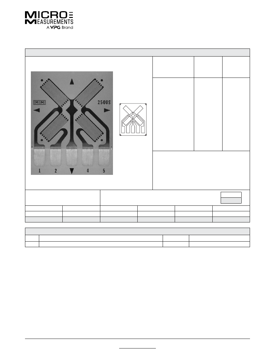
For technical questions, contact
mm@vpgsensors.com
Document No.: 11334
Revision: 15-Nov-2015
www.micro-measurements.com
113
250US
General Purpose Strain Gages—Shear/ Torque Pattern
General Purpose Strain Gages—Shear/ Torque Pattern
GAGE PATTERN DATA
actual size
GAGE
DESIGNATION
See Note 1
RESISTANCE
(OHMS)
OPTIONS
AVAILABLE
See Note 2
CEA-XX-250US-120
CEA-XX-250US-350
120 ± 0.4%
350 ± 0.4%
DESCRIPTION
Four-element full-bridge pattern for shear-strain
measurement. Grids are spaced 90° apart, and 45°
from pattern centerlines. Exposed solder tab area is
0.16 x 0.10 in (4.1 x 2.5 mm).
GAGE DIMENSIONS
Legend
ES = Each Section
CP = Complete Pattern
S = Section (S1 = Section 1)
M = Matrix
inch
millimeter
Gage Length
Overall Length
Grid Width
Overall Width
Matrix Length
Matrix Width
0.250 ES
0.820 CP
0.120 ES
0.700 CP
0.96
0.80
6.35 ES
20.83 CP
3.05 ES
17.78 CP
24.4
20.3
GAGE SERIES DATA
—
See Gage Series datasheet for complete specifications
Series
Description
Strain Range
Temperature Range
CEA
Universal general-purpose strain gages.
±5%
–100° to +350°F (–75° to +175°C)
Note 1:
Insert desired S-T-C number in spaces marked XX.
Note 2:
Products with designations and options shown in bold are not RoHS compliant.
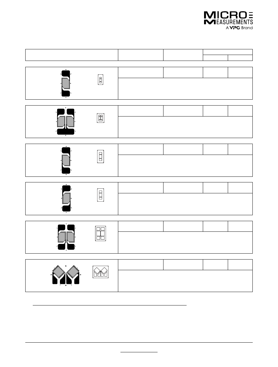
For technical questions, contact
mm@vpgsensors.com
www.micro-measurements.com
114
Document No.: 11324
Revision: 15-Nov-2015
Other Shear/Torque Patterns
General Purpose Strain Gages
General Purpose Strain Gages
GAGE PATTERN
GAGE SERIES
See Note 1
GAGE RESISTANCE
(OHMS)
GAGE LENGTH
inches
millimeters
062DW
actual size
EA, ED,
WA
, WK,
SA,
SK, SD
, WD
120, 350
0.062
1.57
45° torque gage.
Matrix size: 0.30L x 0.15W in. (7.6L x 3.8W mm)
062TW
actual size
EA, WK,
SA, SK
120, 350
0.062
1.52
Two-element 90° torque gage.
Matrix size: 0.27L x 0.21W in. (6.9L x 5.3W mm)
090DW
actual size
EA,
WA
, WK,
SA, SK
120, 350
0.09
2.29
45° torque gage. Larger version of 062DW pattern. See also 090DY pattern.
Matrix size: 0.38L x 0.19W in. (9.6L x 4.8W mm)
090DY
actual size
EA,
WA
, WK,
SA, SK
120, 350
0.09
2.29
45° torque gage. Similar to the 090DW pattern except opposite grid angle.
Matrix size: 0.38L x 0.19W in. (9.7L x 4.8W mm)
125TH
actual size
EA,
WA
, WK,
SA, SK
120, 350
0.125
3.18
Two-element 90° torque gage. Sections are electrically independent.
Matrix size: 0.44L x 0.31W in. (11.2L x 7.9W mm)
125TR
actual size
EA, EK,
S2K, WA
, WK,
SA, SK
120, 350, 1000
0.125
3.18
Two-element 90° torque rosette. EK-Series gages are supplied with duplex
copper dots (DD) when optional feature W or SE is not specified.
Matrix size: 0.36L x 0.47W in. (9.1L x 11.9W mm)
Note 1:
Products with designations and options shown in
bold
are not RoHS compliant.
See http://www.vishaypg.com/micro-measurements/stress-analysis-strain-gages/other-rosettes/
for complete specifications.
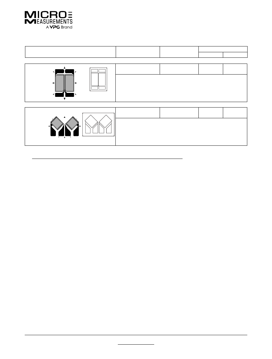
For technical questions, contact
mm@vpgsensors.com
Document No.: 11324
Revision: 15-Nov-2015
www.micro-measurements.com
115
Other Shear/Torque Patterns
General Purpose Strain Gages
GAGE PATTERN
GAGE SERIES
See Note 1
GAGE RESISTANCE
(OHMS)
GAGE LENGTH
inches
millimeters
250TK
actual size
EA,
WA
, WK,
SA, SK
120, 350, 1000
0.25
6.35
Two-element 90° torque gage with compact geometry. Sections are electrically
independent.
Matrix size: 0.74L x 0.55W in. (18.8.3L x 14.0W mm)
250TR
actual size
EA, EK,
S2K, WA,
WK,
SA, SK
120, 350, 1000
0.25
6.35
Two-element 90° rosette for shear-strain and torque measurements. EK-Series
gages are supplied with duplex copper pads (DP) when optional feature W or
SE is not specified.
Matrix size: 0.70L x 0.96W in. (17.8L x 24.4W mm)
Note 1:
Products with designations and options shown in
bold
are not RoHS compliant.
See http://www.vishaypg.com/micro-measurements/stress-analysis-strain-gages/other-rosettes/
for complete specifications.

For technical questions, contact
mm@vpgsensors.com
www.micro-measurements.com
116

For technical questions, contact
mm@vpgsensors.com
www.micro-measurements.com
117
SR-4
®
Strain Gages
PATTERNS
FAE Series ........................................... 118
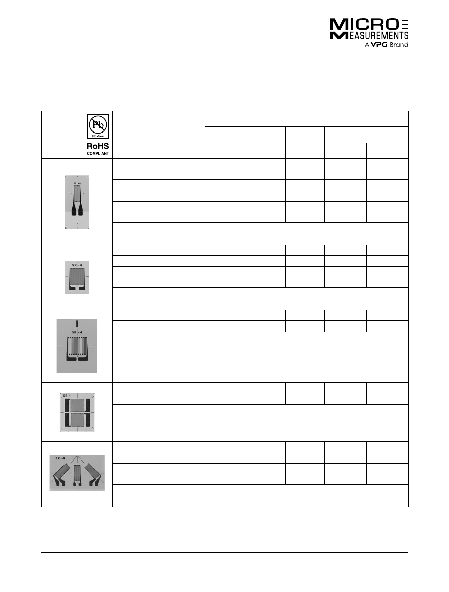
For technical questions, contact
mm@vpgsensors.com
www.micro-measurements.com
118
Document No.: 12204
Revision: 03-Feb-2016
FAE Series
SR-4® (Constantan Foil, Polyimide Carrier) Strain Gages
SR-4
®
(Constantan Foil, Polyimide Carrier) Strain Gages
GAGE
PATTERN
DESIGNATION
RES.
IN
OHMS
DIMENSIONS— inches (millimeters)
GRID
LENGTH
OVERALL
LENGTH
GRID
WIDTH
MATRIX
Length
Width
FAE-25-12SX
120 ±0.2
0.250 (6.35)
0.350 (8.89)
0.125 (3.18) 0.548 (13.92)
0.250 (6.35)
FAE-25-35SX
350 ±0.5
0.250 (6.35)
0.350 (8.89)
0.125 (3.18) 0.548 (13.92)
0.250 (6.35)
FAE-25-100SX
1000 ±0.2
0.235 (5.97) 0.425 (10.79) 0.175 (4.44) 0.710 (18.03)
0.465 (11.81)
FAE-12-12SX
120 ± 0.2
0.125 (3.18)
0.180 (4.57)
0.065 (1.65)
0.354 (8.99)
0.175 (4.45)
FAE-12-35SX
350 ± 0.5
0.125 (3.18)
0.180 (4.57)
0.062 (1.57)
0.359 (9.12)
0.180 (4.57)
FAE-12-100SX
1000 ± 0.2
0.125 (3.18)
0.180 (4.57)
0.062 (1.57)
0.364 (9.25)
0.185 (4.70)
Half-Square Grid—General Purpose
FAE-12S-12SX
120 ± 0.2
0.122 (3.10)
0.190 (4.38)
0.125 (3.18)
0.364 (9.25)
0.240 (6.10)
FAE-12S-35SX
350 ± 0.5
0.122 (3.10)
0.190 (4.38)
0.125 (3.18)
0.375 (9.53)
0.240 (6.10)
FAE-06S-12SX
120 ± 0.2
0.062 (1.57)
0.130 (3.30)
0.062 (1.57)
0.308 (7.82)
0.180 (4.57)
FAE-06S-35SX
350 ± 0.5
0.062 (1.57)
0.130 (3.30)
0.062 (1.57)
0.308 (7.82)
0.180 (4.57)
Square Grid—High Power Dissipation
FAE-03W-12SX
120 ± 0.2
0.031 (0.79)
0.075 (1.90)
0.062 (1.57)
0.269 (6.83)
0.140 (3.56)
FAE-03W-35SX
350 ± 0.5
0.031 (0.79)
0.075 (1.90)
0.062 (1.57)
0.269 (6.83)
0.152 (3.86)
Wide Grid—General Purpose, Low Profile
FAET-12A-12SX
120 ± 0.2
0.125 (3.18)
0.245 (6.22)
0.125 (3.18) 0.475 (12.07)
0.460 (11.68)
FAET-12A-35SX
350 ± 0.5
0.125 (3.18)
0.245 (6.22)
0.125 (3.18) 0.475 (12.07)
0.460 (11.68)
Tee-Rosette—General Purpose
FAER-25B-12SX
120 ± 0.2
0.250 (6.35)
0.380 (9.65)
0.125 (3.18) 0.604 (15.34)
0.935 (23.75)
FAER-25B-35SX
350 ± 0.5
0.250 (6.35)
0.385 (9.78)
0.125 (3.18) 0.600 (15.24)
0.935 (23.75)
FAER-12B-12SX
120 ± 0.2
0.125 (3.18)
0.190 (4.77)
0.062 (1.57)
0.350 (8.89)
0.485 (12.32)
FAER-12B-35SX
350 ± 0.5
0.125 (3.18)
0.190 (4.77)
0.062 (1.57)
0.355 (9.02)
0.500 (12.70)
3 Element Rosette—45° Planar
Following is a representative listing of the most popular gage patterns formerly manufactured by BLH. For availability of
other SR-4 strain gages in other patterns and series—including those for transducer applications—please contact the
Applications Engineering Department.

For technical questions, contact
mm@vpgsensors.com
www.micro-measurements.com
119
Special Use
Sensors
PATTERNS
Residual Stress Patterns .................... 120
Magnetic Field Patterns ..................... 121
Standard Weldable Patterns .............. 122
Sealed Weldable Patterns .................. 124
High-Temperature Weldable
Patterns ............................................. 126
High-Temperature Patterns ................ 128
Shear Modulus Testing Patterns ........ 132
Concrete Embedment Gages ............. 133
SENSORS
Temperature Sensors and LST
Networks ........................................... 134
Manganin Patterns ............................ 137
Crack Detection Patterns .................. 139
Crack Propagation Patterns .............. 141
Linear Displacement Sensor ............. 143
Cable-Extension Displacement
Sensor ............................................... 145
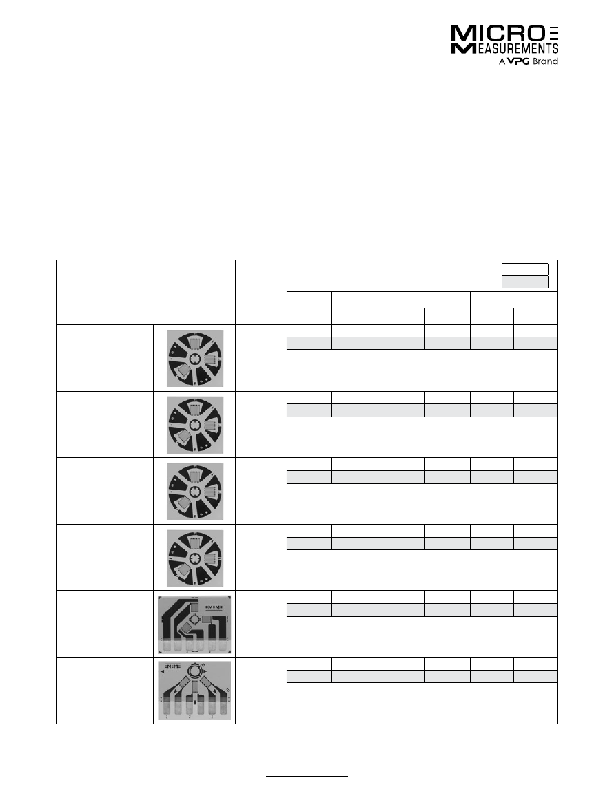
For technical questions, contact
mm@vpgsensors.com
www.micro-measurements.com
120
Document No.: 11516
Revision: 15-Nov-2015
Residual Stress Patterns
Special Use Sensors—Residual Stress Strain Gages
Special Use Sensors—Residual Stress Strain Gages
GAGE PATTERN AND DESIGNATION
Insert Desired S-T-C No. in
Spaces Marked XX.
See Note 1.
RES.
IN
OHMS
DIMENSIONS
inch
millimeter
GAGE
LENGTH
GRID
CTR’LINE
DIA.
TYPICAL HOLE DIA.
MATRIX
Min.
Max.
Length
Width
EA-XX-031RE-120
EA-XX-031RE-120/
SE
120 ± 0.2%
120 ± 0.4%
0.031
0.101
0.03
0.04
0.29
0.29
0.79
2.56
0.8
1.0
7.4
7.04
Due to small pattern size, measurement error can be magnified by
slight mislocation of drill hole. Pattern not recommended for general-
purpose applications.
N2K-XX-030RR-350/DP
350 ± 0.4%
0.30
0.170
0.090
0.100
0.37
0.37
0.76
4.32
2.3
2.5
9.4
9.4
Special six-element configuration that provides somewhat higher
output than three-element designs.
EA-XX-062RE-120
EA-XX-062RE-120/
SE
120 ± 0.2%
120 ± 0.4%
0.062
0.202
0.06
0.08
0.42
0.42
1.57
5.13
1.5
2.0
10.7
10.7
Most widely used RE pattern for general-purpose residual stress
measurement applications.
EA-XX-125RE-120
EA-XX-125RE-120/
SE
120 ± 0.2%
120 ± 0.4%
0.125
0.404
0.12
0.16
0.78
0.78
3.18
10.26
3.0
4.1
19.8
19.8
Larger version of the 062RE pattern.
CEA-XX-062UL-120
120 ± 0.4%
0.062
0.202
0.06
0.08
0.50
0.62
1.57
5.13
1.5
2.0
12.7
15.7
Fully encapsulated with large copper-coated soldering tabs. Same
pattern geometry as 062RE pattern.
CEA-XX-062UM-120
120 ± 0.4%
0.062
0.202
0.06
0.08
0.38
0.48
1.57
5.13
1.5
2.0
9.6
12.2
Fully encapsulated with large copper-coated soldering tabs and special
trim alignment marks. Trim line spaced 0.068 in (1.73 mm) from hole
center. Limitations may exist in data reduction equations.
Note 1:
Products with designations and options shown in bold are not RoHS compliant.
The most widely used practical technique for determining
residual stresses is the hole-drilling strain gage method
described in ASTM Standard E837. With this method,
a specially configured strain gage rosette is bonded to
the surface of the test object; and a small, shallow hole
is introduced into the structure, through the center of
the gage, with a precision drilling apparatus. Strains in
the immediate vicinity of the hole are measured, and
the relaxed residual stresses are computed from these
measurements. The general theory of making residual
stress measurements is covered in Micro-Measurements
Tech Note TN-503, “Measurement of Residual Stresses
by the Hole-Drilling Strain Gage Method” and the requisite
hardware is described in Datasheet 11304.
CONSTRUCTION
All gages are constructed of self-temperature-
compensated foil (06 and 13 S-T-C) on a flexible
polyimide carrier, and incorporate a centering target for
use with a precision milling guide. EA-Series (A-Alloy)
gages are available “open-faced” or with solder dots and
encapsulation (Option SE); CEA-Series (A-Alloy) gages
have encapsulated grids, and rugged, copper-coated
solder tabs. Construction of the N2K Series (K-alloy) is
similar to the N2A Series and includes copper pads (DP)
on the solder tabs. The 062UM gage permits installation
adjacent to weldments and intersecting surfaces.
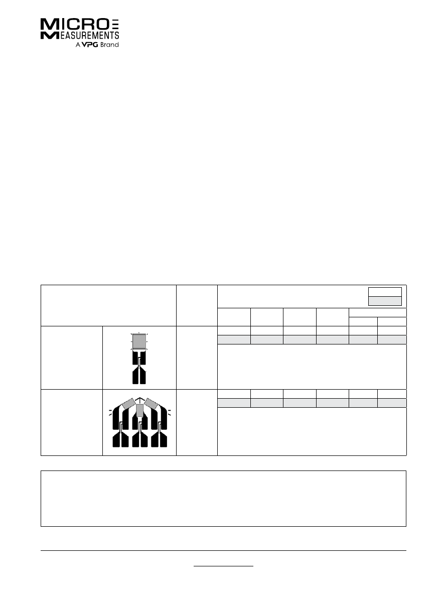
For technical questions, contact
mm@vpgsensors.com
Document No.: 11517
Revision: 15-Nov-2015
www.micro-measurements.com
121
Magnetic Field Patterns
Special Use Sensors—Magnetic Field Strain Gages
Special Use Sensors—Magnetic Field Strain Gages
GAGE PATTERN
AND DESIGNATION
RES.
IN
OHMS
DIMENSIONS
Legend:
ES = Each Section
inch
millimeter
GAGE
LENGTH
OVERALL
LENGTH
GRID
WIDTH
OVERALL
WIDTH
MATRIX
Length
Width
H06A-AC1-125-700
700 ± 0.5%
0.125
0.49
0.125
0.125
0.61
0.22
3.18
12.4
3.18
3.18
15.5
5.6
Single-axis pattern with integral copper terminals.
H06A-AD3-125-700
700 ± 0.5%
0.125 ES
0.56
0.080 ES
0.620
0.65
0.70
3.18 ES
14.2
2.03 ES
15.75
16.5
17.8
Three-element 60° delta rosette with integral copper terminals.
Where magnetic noise is likely to be encountered, the selection of the strain gage grid alloy should be given careful
consideration. If the grid alloy is magnetic, it will be subject to extraneous physical forces in a magnetic field; and,
if magnetoresistive, will undergo spurious resistance changes. Similarly, if the alloy is magnetostrictive, the grid
will tend to change length in the magnetic field. While constantan is comparatively free from magnetic effects over
its normal operating temperature range, specific measurement applications may indicate desirability of a different
sensing grid alloy. Contact our Applications Engineering Department for details.
Intense, time-varying electromagnetic fields with steep
gradients in field strength can cause troublesome noise
in strain gage circuits. In severe magnetic environments,
with low signal levels, the noise amplitude may be
several times larger than the strain signal from the gage.
Micro-Measurements H-Series noninductive strain gages
have been specially designed to minimize noise pickup in
the gage grid due to electromagnetic fields.
H-Series strain gages consist of two identical grids,
with one stacked directly above and insulated from, the
other. The upper and lower grid elements are connected
in series so that current flows in opposite directions
through the two grids. With this arrangement, noise
voltages induced in the grid tend to be self-cancelling.
The counter-current principle employed in H-Series gages
is particularly effective against magnetic field gradients
parallel to the test surface.
H-Series strain gages have been used very successfully
in fusion research applications and similar environments
with flux densities to 50 000 gauss.
CONSTRUCTION
H-Series strain gages are constructed with two 350-ohm
constantan alloy foil grids on a glass-fiber-reinforced
epoxy phenolic carrier. These fully encapsulated gages
include closely spaced, heavy copper terminals for direct
leadwire attachment. H-Series gages are available in
both a single axis and a delta (60°) rosette pattern. The
available S-T-C number is 06.
ADHESIVES
Micro-Measurements M-Bond 600 or AE-15 adhesive
systems are particularly recommended; M-Bond 600
produces the thinnest glueline. Adhesive cure temperature
should not exceed the maximum sensor operating
temperature of +250°F (+120°C).
LEADWIRES
In many cases, the leadwire system itself is the principal
source of magnetic noise induction in the measuring
circuit. Careful attention to details as outlined in
Micro-Measurements Tech Note TN-501, “Noise Control
in Strain Gage Measurements”, is strongly recommended.
For technical questions, contact
mm@vpgsensors.com
www.micro-measurements.com
122
Document No.: 11519
Revision: 15-Nov-2015
Standard Weldable Patterns
Special Use Sensors—Weldable Strain Gages
Special Use Sensors—Weldable Strain Gages
Micro-Measurements Standard Weldable Strain Gages
and Temperature Sensors are specially designed for spot
welding to structures and components. They are ideal
for applications where test or environmental conditions
preclude clamping and curing an adhesively bonded
gage installation. These gages are equally advantageous
when strain measurements must be made at an elevated
temperature, but the nature of the test object does
not permit the use of an elevated-temperature-curing
adhesive.
Surface preparation requirements are minimal; only an
appropriate solvent cleaning and abrasion of the test part
surface with silicon-carbide paper or a small, hand-held
grinder is needed. Spot welding is accomplished with
a portable stored-energy hand-probe spot welder, such
as the Model 700. Environmental protection is as easily
applied to a welded gage installation as to an adhesively
bonded gage.
Refer to Instruction Bulletin B-131 and MM Strain
Gage Accessories Data Book for further information on
installation and protective coatings. For specifications
about the Model 700 Welding/Soldering Unit, please refer
to the product datasheet.
DESCRIPTION AND PERFORMANCE
General
—All sensors are laboratory-prebonded, with a
high-performance adhesive, to thin [0.005 in (0.13 mm)]
metal carriers. Sensor grids are fully encapsulated for
protection against handling and installation damage.
Standard weldable strain gages are offered in two
series to meet differing performance requirements. Both
series are available in either 06 or 09 self-temperature
compensation. Strain gages with 06 S-T-C have Inconel
carriers, while S-T-C 09 gages and temperature sensors
are mounted on 300-series stainless steel.
CEA-Series Weldable Strain Gage
—Polyimide-
encapsulated constantan foil grid, with large, rugged,
copper-coated tabs. In most cases, the carrier can be
contoured to a radius as small as 1/2 in (13 mm). The CEA
Series is ideal for direct leadwire attachment, before or
after installation.
Strain range is ±5000 μin/in (±5000 μm/m), and normal
operating temperature range is –100° to +200°F (–75°
to +95°C). Short-term maximum temperature is +300°F
(+150°C).
LWK-Series Weldable Strain Gage
—Nickel-chromium
alloy grid, encapsulated in fiberglass-reinforced epoxy
phenolic. The LWK gage is provided with a three-wire lead
system with 10 in (250 mm) of Teflon
®
-insulated leadwire.
This construction simplifies leadwire temperature
compensation and provides for easy connection of the
lead system to the instrumentation cable. Minimum
installation radius is generally limited to 2 in (50 mm).
Strain range is ±5000 μin/in (±5000 μm/m), and normal
operating temperature range is –320° to +500°F (–195°
to +260°C). Short-term maximum temperature is +550°F
(+290°C).
WWT-Series Temperature Sensor
—High-purity nickel
foil grid encapsulated in fiberglass-reinforced epoxy-
phenolic, and equipped with integral three-tab terminal
to facilitate leadwire attachment. The temperature sensor
is normally installed on a flat surface of the workpiece,
but, in any case, should always be oriented with the
gridlines in the direction of minimum strain to avoid strain-
induced errors (see Micro-Measurements Tech Note
TN-506, “Bondable Resistance Temperature Sensors and
Associated Circuitry”). With an appropriate LST Matching
Network, the temperature response characteristic of the
nickel can be linearized and scaled for direct readout (in
degrees) with any strain indicator.
Teflon is a Registered Trademark of DuPont.
MEASUREMENT CONSIDERATIONS
It is important to note that operating characteristics
of weldable strain gages (gage factor, transverse
sensitivity, and thermal output) are specified for the
basic strain gage itself—without the metal carrier. Thus,
the properties are measured by bonding a conventional
strain gage directly to an appropriate calibration
specimen, following standard methods specified for
all Micro-Measurements strain gages. This procedure
assures the most accurate results, independent of
the variables introduced by welding. In particular, the
user should be aware that the gage factor specified
on the engineering data sheet accompanying the gage
applies only to the basic strain gage, without the shim.
The effective gage factor of the weldable assembly
(after welding to the test member) is commonly 5 to
10% lower than this, due primarily to the stiffness of
the shim. The reduction in gage factor is not subject to
quantitative generalization, because it depends on the
cross-sectional properties of the test specimen, and
on the mode of loading (e.g., bending versus direct
stress). It has been demonstrated, however, that for a
group of like specimens, loaded in the same manner,
the weldable gages exhibit very good repeatability
and uniformity of response. Therefore, when test
requirements dictate greatest accuracy, the weldable
gages should be calibrated on a specimen of the same
material and cross section as the test part, and under
the same mode of loading.
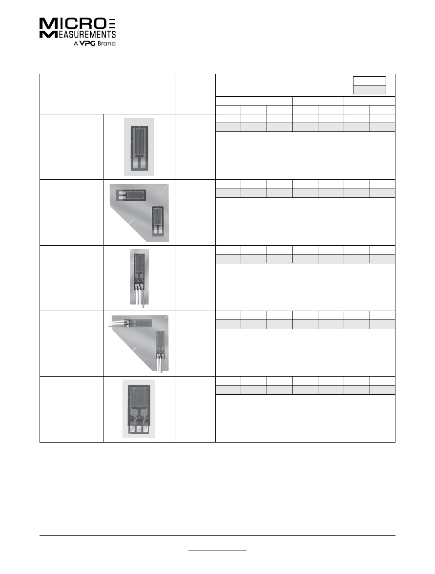
For technical questions, contact
mm@vpgsensors.com
Document No.: 11519
Revision: 15-Nov-2015
www.micro-measurements.com
123
Standard Weldable Patterns
Special Use Sensors—Weldable Strain Gages
GAGE PATTERN AND DESIGNATION
Insert Desired S-T-C No.
in Spaces Marked XX.
See Note 1
RES.
IN
OHMS
DIMENSIONS
Legend:
ES = Each Section
inch
millimeter
CARRIER
ACTIVE GRID
MATRIX
Length
Width
Thick
Length
Width
Length
Width
CEA-XX-W250A-120
CEA-XX-W250A-350
120 ± 0.4%
350 ± 0.4%
0.63
0.34
0.005
0.230
0.125
0.44
0.17
16.0
8.6
0.13
5.84
3.18
11.2
4.3
Most flexible and conformable pattern. Type 326-DFV and
330-DFV flat three-conductor cable typically used to solder
directly to copper-coated tabs.
CEA-XX-W250C-120
CEA-XX-W250C-350
120 ± 0.4%
350 ± 0.4%
0.90
0.90
0.005
0.230
0.125
0.44
0.17
22.9
22.9
0.13
5.84
3.18
11.2
4.3
Tee rosette, used in biaxial stress states where directions of
principal stresses are known. See W250A pattern for typical
leadwire recommendations.
LWK-XX-W250B-350
350 ± 0.4%
0.88
0.32
0.005
0.250
0.125
0.62
0.17
22.4
8.1
0.13
6.35
3.18
15.7
4.3
Wide-temperature-range linear pattern with 10 in (250 mm)
preattached leads. Teflon insulation is pretreated for best bond to
protective coatings.
LWK-XX-W250D-350
350 ± 0.4%
1.15
1.15
0.005
0.250
0.125
0.62
0.17
29.2
29.2
0.13
6.35
3.18
15.7
4.3
Tee rosette, used in biaxial stress states where directions of
principal stresses are known and a wide operating temperature
range is required.
WWT-TG-W200B-050
50 ± 0.4%
@ +75°F
(+24°C)
0.71
0.43
0.005
0.200
0.200
0.52
0.26
18.0
10.9
0.13
5.08
5.08
13.1
6.6
Easy-to-use temperature sensor that can be welded or adhesively
bonded to the test structure. For standard bondable temperature
sensors, see Document Number 11522, “Temperature Sensors
and LST Networks.”
Note 1:
Products with designations and options shown in bold are not RoHS compliant.
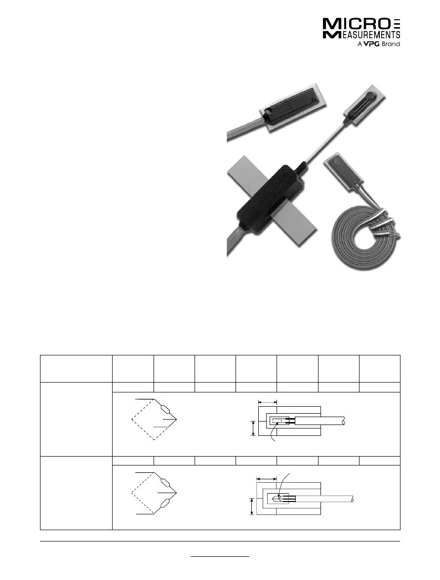
For technical questions, contact
mm@vpgsensors.com
www.micro-measurements.com
124
Document No.: 11533
Revision: 15-Nov-2015
Sealed Weldable Patterns
Special Use Sensors—Weldable Strain Gages
Special Use Sensors—Weldable Strain Gages
DESIGNATION
NOMINAL
RESISTANCE
(Ohms)
NOMINAL
GAGE
FACTOR
GRID
GEOMETRY
GAGE
LENGTH
(in)
LEADWIRE
SHIM
LENGTH
(in)
SHIM
WIDTH
(in)
LEA-06-W125E-350/3R
350
2.0
Axial
0.125
Vinyl
0.8
0.4
Black
White
Red
0.20"
0.30"
EA-06-125BZ-350
HBW-35-125-6-3VR
Bridge Circuit
Configuration
LEA-06-W125F-350/3R
350
2.0
Shear
0.125
Vinyl
1.0
0.5
Black
Red
White
EA-06-125TK-350
0.25"
0.35"
HBWS-35-125-6-3VR
Bridge Circuit
Configuration
Micro-Measurements Sealed Weldable Strain Gages
are specially designed for spot welding to structures
and components. They are ideally used for applications
where test or environmental conditions preclude clamping
and curing an adhesively bonded gage installation.
These gages are equally advantageous when strain
measurements must be made at elevated temperatures,
but the nature of the test object does not permit the use
of an elevated temperature-curing adhesive. Additionally,
all Micro-Measurements Sealed Weldable Strain Gages
come with a preinstalled protective coating providing
both protection in moist environments and savings in the
time and effort required for making the complete gage
installation.
All sensors are fabricated with EA-Series strain gages,
laboratory-prebonded with a high-performance adhesive
to a thin [0.005 in (0.127 mm)] stainless steel carrier, and
fully encapsulated for protection against moisture. They
have a ±5000 microinch/in strain range, and a normal
operating temperature range of –40°F (–40°C) to +180°F
(+83°C). These gages can be used on surfaces with a
radius of curvature of 3.0 in (76 mm) or greater.
The three leadwire-series of Micro-Measurements Sealed
Weldable Strain Gages have physical constructions
designed for various environmental exposures and
installation constraints.
R-LEADWIRE-SERIES
These gages are designed for long-term out-of-doors use. Primarily used in applications such as railroad and civil
structures, they can be exposed to oil and water splash and short-term submersion in water of shallow [24 in (60 cm)]
depth. The metal carrier is processed to give good first cycle data, excellent fatigue resistance and a high strain range.
Exposure of the vinyl-insulated cable to strong solvents—especially MEK—should be avoided to prevent damage. Long-
term exposure to sub-freezing temperatures requires careful handling to avoid cracking of the vinyl insulation.
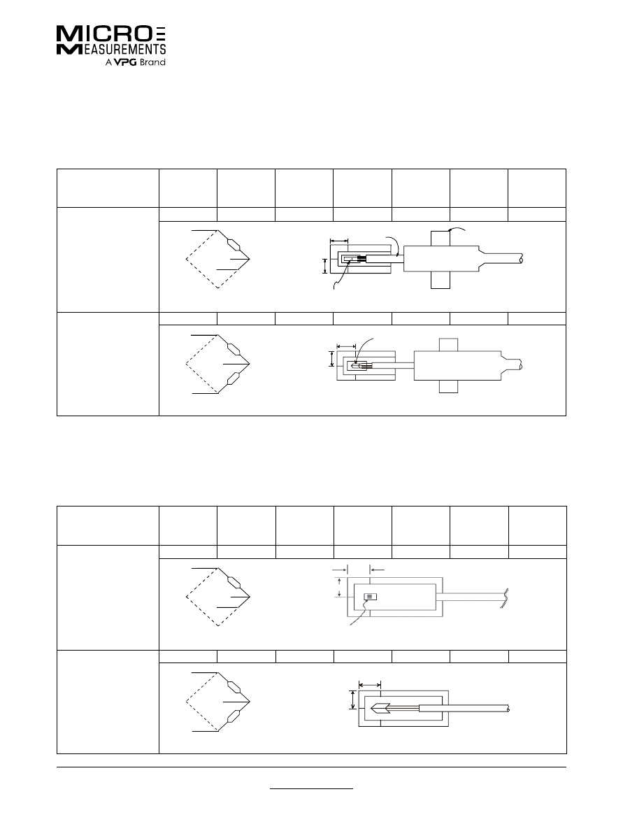
For technical questions, contact
mm@vpgsensors.com
Document No.: 11533
Revision: 15-Nov-2015
www.micro-measurements.com
125
Sealed Weldable Patterns
Special Use Sensors—Weldable Strain Gages
T-LEADWIRE-SERIES
This series is designed to withstand exposure to water pressures of up to 500 psi. They can also withstand short-term
(up to 14 days) immersion in crude oil. A flexible stainless steel tube, providing wire routing from the strain gage to a
cable transition, enables fine positioning of the sensor as well as providing strain relief. These sensors are typically used
on larger civil structures, including bridges, dams, and buildings, or for exposures of up to a year in seawater.
DESIGNATION
NOMINAL
RESISTANCE
(Ohms)
NOMINAL
GAGE
FACTOR
GRID
GEOMETRY
GAGE
LENGTH
(in)
LEADWIRE
SHIM
LENGTH
(in)
SHIM
WIDTH
(in)
LEA-06-W125E-350/10T
350
2.0
Axial
0.125
Shielded Vinyl
0.8
0.4
Black
White
Red
for LEA-06-W125E-350/10T illustration
EA-06-125BZ-350
0.20"
0.30"
TRANSISTION
WELDABLE ANCHOR SHIM
S.S. TUBE 1.5"
Bridge Circuit
Configuration
LEA-06-W125F-350/10T
350
2.0
Shear
0.125
Shielded Vinyl
1.0
0.5
Black
Red
White
EA-06-125TK-350
0.35"
0.25"
HBWS-35-125-6-10GP-SS
Bridge Circuit
Configuration
L-LEADWIRE-SERIES
The L-Leadwire-Series sensors are designed to have a performance similar to the T-Leadwire-Series but without a cable
transition. They can be used in similar applications when the sensor will be exposed to smaller strains, and care can be
taken during installation to anchor the leadwire to provide for strain relief. The L-Leadwire-Series gages are particularly
useful where space constraints preclude the use of the cable transition of T-Leadwire-Series gages.
DESIGNATION
NOMINAL
RESISTANCE
(Ohms)
NOMINAL
GAGE
FACTOR
GRID
GEOMETRY
GAGE
LENGTH
(in)
LEADWIRE
SHIM
LENGTH
(in)
SHIM
WIDTH
(in)
LEA-06-W125E-350/10L
350
2.0
Axial
0.125
Shielded Vinyl
1.5
0.6
Black
White
Red
0.35"
0.30"
EA-06-125BZ-350
Bridge Circuit
Configuration
LEA-06-W125F-350/10L
350
2.0
Shear
0.125
Shielded Vinyl
1.5
0.6
Black
Red
White
HBWS-35-125-6-GP-NT
0.35"
0.30"
Bridge Circuit
Configuration
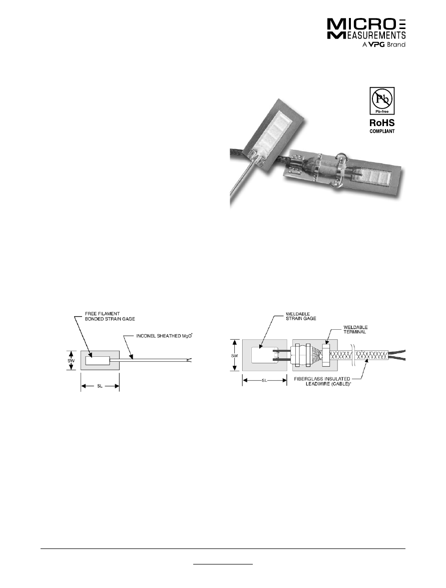
For technical questions, contact
mm@vpgsensors.com
www.micro-measurements.com
126
Document No.: 11530
Revision: 14-Aug-2015
High-Temperature Weldable Patterns
Special Use Sensors—Weldable Strain Gages
Special Use Sensors—Weldable Strain Gages
FEATURES
• High temperature installations using simple attachment
techniques
• Ceramic bonded wire gage performance in a weldable
gage
• Superior performance of bonded gages
• Improved fatigue life for dynamic applications
Micro-Measurements high-temperature weldable strain
gages are free-filament wire strain gages pre-bonded
to shim stock using flame sprayed alumina. The gages
can be welded to the test structure using a capacitive
discharge spot welder (such as Micro-Measurements
Model 700), permitting easy installation in the field,
especially on large structures. High-temperature weldable
strain gages are excellent in applications where protection
against moisture is not required. The fatigue resistance
of this bonded wire strain gage makes it the best choice
for dynamic, impact or vibratory strain measurements
to 1800°F (980°C). Their use in measuring static strains
should be avoided.
High-temperature weldable strain gages are available
with grids of Nichrome V (N) or Pt8W (E) alloys. They
can be ordered with either of two types of preattached
high-temperature insulated cable.
GAGES WITH M-SERIES LEADWIRES
GAGES WITH F-SERIES LEADWIRES
Complete assembly consists of a free-filament gage
bonded to a shim with an integral high-temperature
cable with chromel/alumel wires. The mineral insulated,
two-conductor cable with an Inconel metal jacket is
rated to 1800°F (980°C) and offers excellent protection in
harsh environments. While the ends are sealed to avoid
moisture absorption during shipping or storage, care
should be taken when using M-Series cables to ensure
that the mineral insulation does not absorb moisture
during handling and application.
Complete assembly consists of a free-filament gage
bonded to a shim, a weldable transition terminal and
a high temperature cable with chromel/alumel wire.
A fiberglass-insulated braided, two-conductor cable
assembly is attached at the gage end through alumina
insulators strap-welded to the terminal shim, providing
a firm anchor for the cable at the gage end. The cable
conductors are threaded through lengthwise holes in the
alumina insulators and bonded to the insulators with high
strength ceramic cement to prevent wire movement at
the gage—cable weld junction. The fiberglass cable is
rated to 1200°F (650°C) and is used where fraying due
to vibration is not a concern. F-Series cables are more
flexible than M-Series cables.
For technical questions, contact
mm@vpgsensors.com
Document No.: 11530
Revision: 14-Aug-2015
www.micro-measurements.com
127
High-Temperature Weldable Patterns
Special Use Sensors—Weldable Strain Gages
DESIGNATION
NOMINAL
RESISTANCE
NOMINAL
GAGE
FACTOR
SENSOR
ALLOY
SENSOR
GAGE
LENGTH
MAX.
TEMP.
LEADWIRE
SHIM
LENGTH
(SL)
SHIM
WIDTH
(SW)
LEAD
TERMINAL
LZN-NC-W250G-120/2F
120 Ω
2.0
NiChrome
V
0.25 in
(6.35 mm)
1200°F
(649°C)
Chromel-
Alumel
0.50 in
(12.7 mm)
0.30 in
(7.62 mm)
Yes
LZN-NC-W250G-120/2M
1600°F
(871°C)
None
LZE-NC-W250G-120/2F
120 Ω
4.0
Pt8W
0.25 in
(6.35 mm)
1200°F
(649°C)
Chromel-
Alumel
0.50 in
(12.7 mm)
0.30 in
(7.62 mm)
Yes
LZE-NC-W250G-120/2M
1600°F
(871°C)
None
NOTE
The standard leadwire length is indicated, in feet, by the number to the left of the last letter of the gage designation. For example, /2F
indicates 2 feet of fiberglass insulated leadwire. Gages with longer leadwires (up to 50 feet) are available on special order.
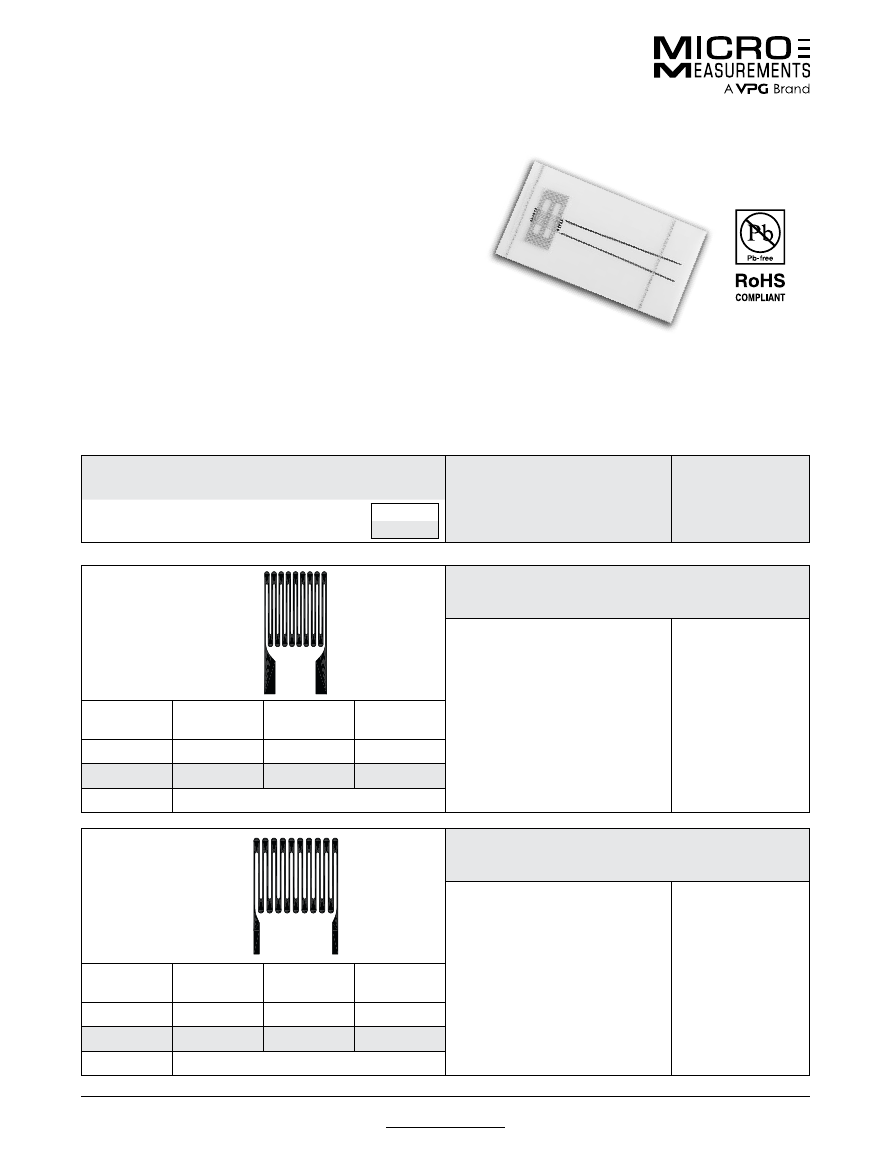
For technical questions, contact
mm@vpgsensors.com
www.micro-measurements.com
128
Document No.: 11532
Revision: 27-Apr-2015
High-Temperature Patterns
Special Use Sensors—High-Temperature Strain Gages
Special Use Sensors—High-Temperature Strain Gages
FEATURES
• Measurement range to 2100°F (1150°C)
• Free-filament Kanthal alloy grids for bonding with
ceramic adhesives
• Linear and Tee-rosette patterns
ZC-Series strain gages are etched Kanthal (Fe-Cr-Al
alloy) foil grids in free-filament form for high-temperature
applications. They are bonded with either ceramic
adhesives, or by the use of flame spray.
ZC-Series strain gages cannot be self-temperature
compensated, and a dummy compensating gage must
be used for minimizing of thermally induced apparent
strain (thermal output). Several patterns are available with
built-in compensating grids.
ZC-Series strain gages are supplied with a removable
high-temperature carrier for gage handling during
instal lation. All patterns have 1 in (25.4 mm) Nichrome
ribbon leads spot welded to the gage tabs for leadwire
attachment.
G1262
Square linear pattern.
ZC-NC-G1262-120
120
GAGE
LENGTH
OVERALL
LENGTH
GRID
WIDTH
OVERALL
WIDTH
0.062
0.150
0.076
0.076
1.57
3.81
1.93
1.93
MATRIX SIZE
N/A
G1263
Wide linear pattern.
ZC-NC-G1263-120
120
GAGE
LENGTH
OVERALL
LENGTH
GRID
WIDTH
OVERALL
WIDTH
0.100
0.248
0.179
0.179
2.54
6.30
4.55
4.55
MATRIX SIZE
N/A
GAGE PATTERN
Not actual size shown. Enlarged when necessary for definition.
GAGE DESIGNATION
RES. IN OHMS
DIMENSIONS
inch
millimeter
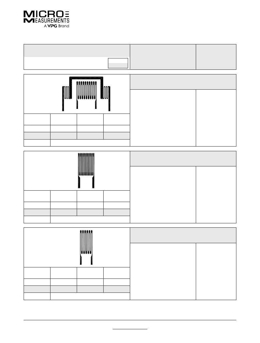
For technical questions, contact
mm@vpgsensors.com
Document No.: 11532
Revision: 27-Apr-2015
www.micro-measurements.com
129
High-Temperature Patterns
Special Use Sensors—High-Temperature Strain Gages
GAGE PATTERN
Not actual size shown. Enlarged when necessary for definition.
GAGE DESIGNATION
RES. IN OHMS
DIMENSIONS
inch
millimeter
G1264
Linear pattern with inactive temperature-compensating grid.
ZC-NC-G1264-120
120
GAGE
LENGTH
OVERALL
LENGTH
GRID
WIDTH
OVERALL
WIDTH
0.100
0.310
0.179
0.430
2.54
7.87
4.55
10.92
MATRIX SIZE
N/A
G1265
Linear pattern.
ZC-NC-G1265-120
120
GAGE
LENGTH
OVERALL
LENGTH
GRID
WIDTH
OVERALL
WIDTH
0.138
0.300
0.138
0.138
3.51
7.62
3.51
3.51
MATRIX SIZE
N/A
G1266
G1272
Linear pattern. Higher resistance linear pattern.
ZC-NC-G1266-120
ZC-NC-G1272-350
120
350
GAGE
LENGTH
OVERALL
LENGTH
GRID
WIDTH
OVERALL
WIDTH
0.200
0.380
0.135
0.135
5.08
9.65
3.43
3.43
MATRIX SIZE
N/A
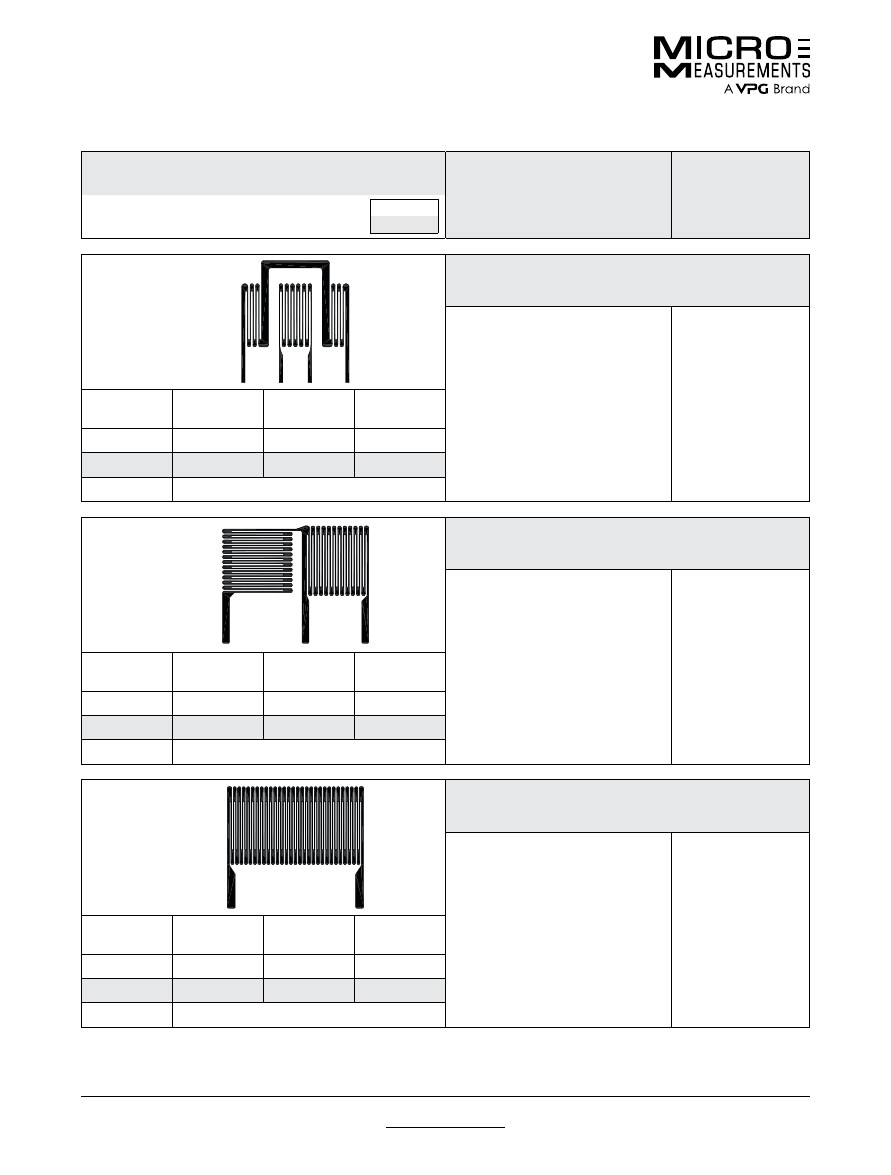
For technical questions, contact
mm@vpgsensors.com
www.micro-measurements.com
130
Document No.: 11532
Revision: 27-Apr-2015
High-Temperature Patterns
Special Use Sensors—High-Temperature Strain Gages
GAGE PATTERN
Not actual size shown. Enlarged when necessary for definition.
GAGE DESIGNATION
RES. IN OHMS
DIMENSIONS
inch
millimeter
G1267
Linear pattern with inactive temperature-compensating grid.
ZC-NC-G1267-120
120
GAGE
LENGTH
OVERALL
LENGTH
GRID
WIDTH
OVERALL
WIDTH
0.200
0.503
0.134
0.442
5.08
12.78
3.40
11.23
MATRIX SIZE
N/A
G1269
G1275
Tee-rosette pattern in half-bridge configuration.
ZC-NC-G1269-200
ZC-NC-G1275-350
120
350
GAGE
LENGTH
OVERALL
LENGTH
GRID
WIDTH
OVERALL
WIDTH
0.125
0.278
0.150
0.346
3.18
7.06
3.81
8.79
MATRIX SIZE
N/A
G1270
Higher resistance linear pattern.
ZC-NC-G1270-350
350
GAGE
LENGTH
OVERALL
LENGTH
GRID
WIDTH
OVERALL
WIDTH
0.100
0.250
0.280
0.300
2.54
6.35
7.11
7.62
MATRIX SIZE
N/A
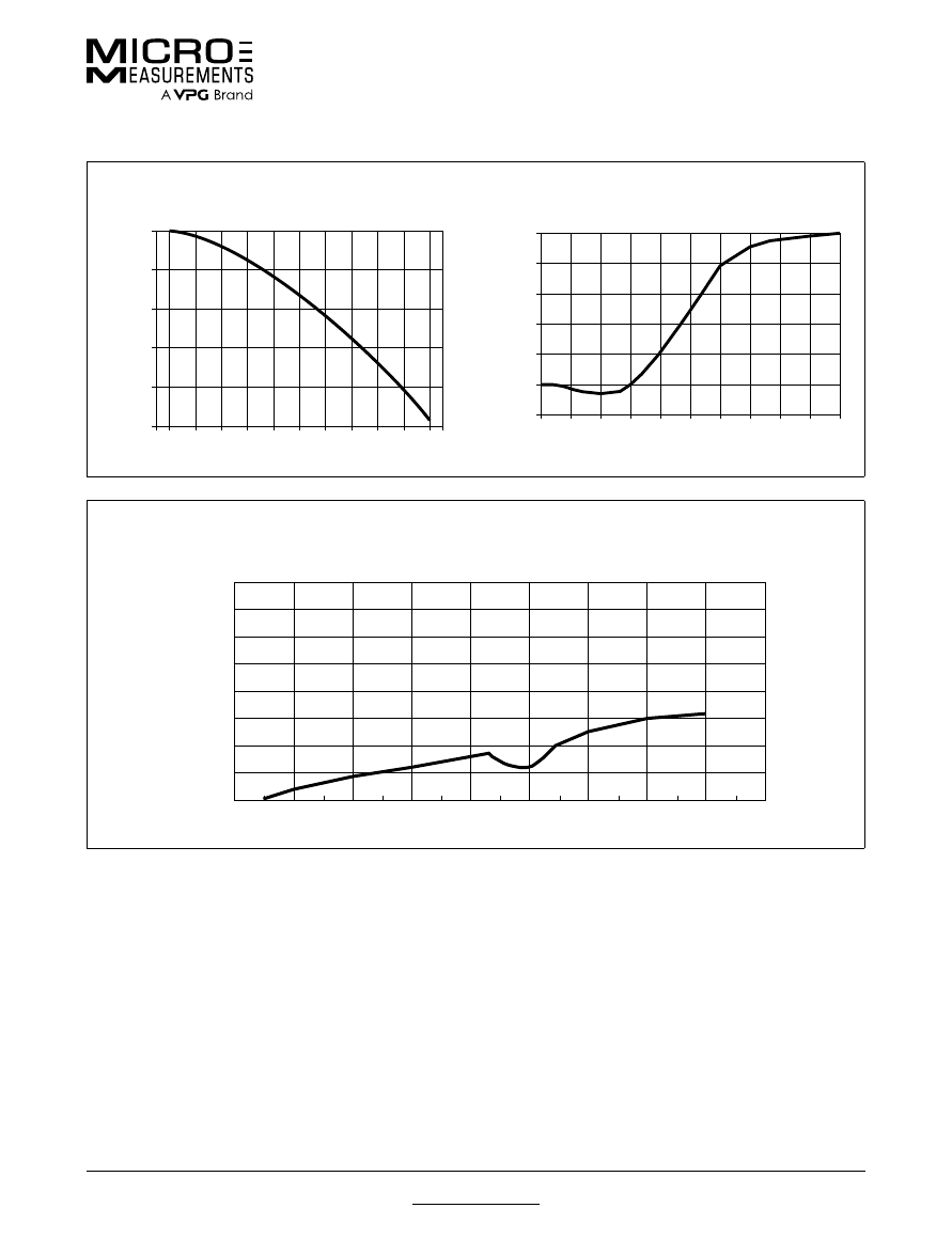
For technical questions, contact
mm@vpgsensors.com
Document No.: 11532
Revision: 27-Apr-2015
www.micro-measurements.com
131
High-Temperature Patterns
Special Use Sensors—High-Temperature Strain Gages
°F
0 200 400 600 800 1000 1200 1400 1600 1800 2000
0
–5
–10
–15
–20
–25
Gage Factor Change (%
)
GAGE FACTOR VARIATION WITH TEMPERATURE FOR
ZC-SERIES GAGE
°C
–18 93 204 315 427 538 649 760 871 982 1093
0
10000
8000
6000
4000
2000
–2000
TYPICAL APPARENT STRAIN
ZC-SERIES GAGE ON TITANIUM WITH H CEMENT
°F
0
200 400 600 800 1000 1200 1400 1600 1800 2000
°C
–18 93 204 315 427 538 649 760 871 982 1093
Microstrain
APPARENT STRAIN/THERMAL OUTPUT FOR LINEAR GRID
WITH TEMPERATURE COMPENSATING DUMMY GRID ON TITANIUM
(GAGE TYPE: ZC-NC-G1267-120)
1600
1400
1200
1000
800
600
400
200
0
0
200
400
600
800
1000
1200
1400
1600
1800
Degrees F
Microstrain
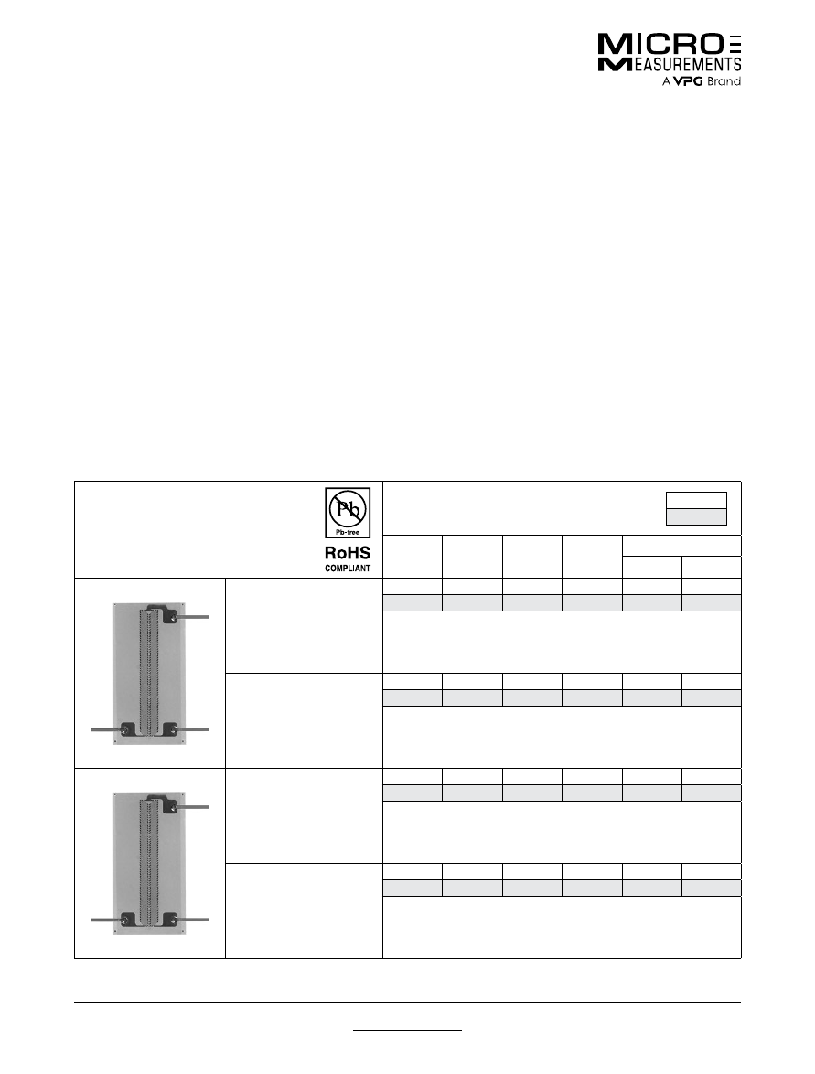
For technical questions, contact
mm@vpgsensors.com
www.micro-measurements.com
132
Document No.: 11525
Revision: 15-Nov-2015
Shear Modulus Testing Patterns
Special Use Sensors—Shear Modulus Testing Strain Gages
Special Use Sensors—Shear Modulus Testing Strain Gages
GAGE PATTERN
AND DESIGNATION
Insert Desired S-T-C No. in Spaces
Marked XX.
DIMENSIONS
Legend:
ES = Each Section
inch
millimeter
GAGE
LENGTH
OVERALL
LENGTH
GRID
WIDTH
OVERALL
WIDTH
MATRIX
Length
Width
N2A-XX-C032A-500/SP61
N2P-08-C032A-500/SP61
0.032 ES
0.462
0.031 ES
0.197
0.500
0.257
0.81 ES
11.73
0.79 ES
5.00
12.7
6.5
For use with losipescu specimens.
N2A-XX-C032B-500/SP61
N2P-08-C032B-500/SP61
0.032 ES
0.762
0.031 ES
0.197
0.800
0.257
0.81 ES
19.35
0.79 ES
5.00
20.3
6.5
For use with compact specimens.
A2A-XX-C085C-500
A2P-08-C085C-500
0.085 ES
0.445
0.070
0.200
0.500
0.260
2.16 ES
11.30
1.78
5.08
12.7
6.6
For use with losipescu specimens.
A2A-XX-C085D-500
A2P-08-C085D-500
0.085 ES
0.745
0.070
0.200
0.805
0.260
2.16 ES
18.92
1.78
5.08
20.4
6.6
For use with compact specimens.
Shear Modulus Sensors are specifically designed to
accommodate the unique specimen geometries and
strain-field distributions encountered when testing
composite materials for shear properties. Two popular
specimens for in-plane shear modulus testing of
composites are the Iosipescu and compact designs.
The test section for both types is described as the
area between two opposing notches. The Iosipescu
specimen has a distance between the notch roots of
0.45 in (11.4 mm); for the compact design this distance
is 0.75 in (19 mm). Both of these specimens have an
inherently nonuniform shear-strain distribution in their test
zone. Determining shear modulus requires extracting an
average shear-strain value from this nonuniform strain
field. Since strain gages have the unique characteristic
of integrating the surface strain field under their grids,
average specimen strain is automatically obtained by
spanning the entire length of either specimen’s test
section.
Two 500 Ω ±0.4%, ±45° shear-gage configurations are
available for both the Iosipescu and compact specimen
designs. The planar configuration, with side-by-side
grids, is constructed with a standard N2 backing and
Option SP61 (soft, copper lead ribbons and polyimide film
encapsulation). The stacked configuration is produced
with a special backing, A2. This backing is similar to
N2 but is fully encapsulated with a polyimide film and
includes integral soft, copper lead ribbons (like those
provided by Option SP61). The stacked configuration is
offered to best simulate strain measurement at a point.
The stacked gages are supplied in a quarter-bridge
arrangement so that independent gage measurements
can be made if necessary. When connected in a half-
bridge circuit, the stacked construction inherently
provides temperature compensation and insensitivity to
normal strains. Due to the increased stiffness of a stacked
sensor, compared to one having only a single layer, an
evaluation of the test conditions and requirements should
be made to ensure that the gage will not compromise
accuracy by significantly reinforcing low-modulus and/or
thin specimens.
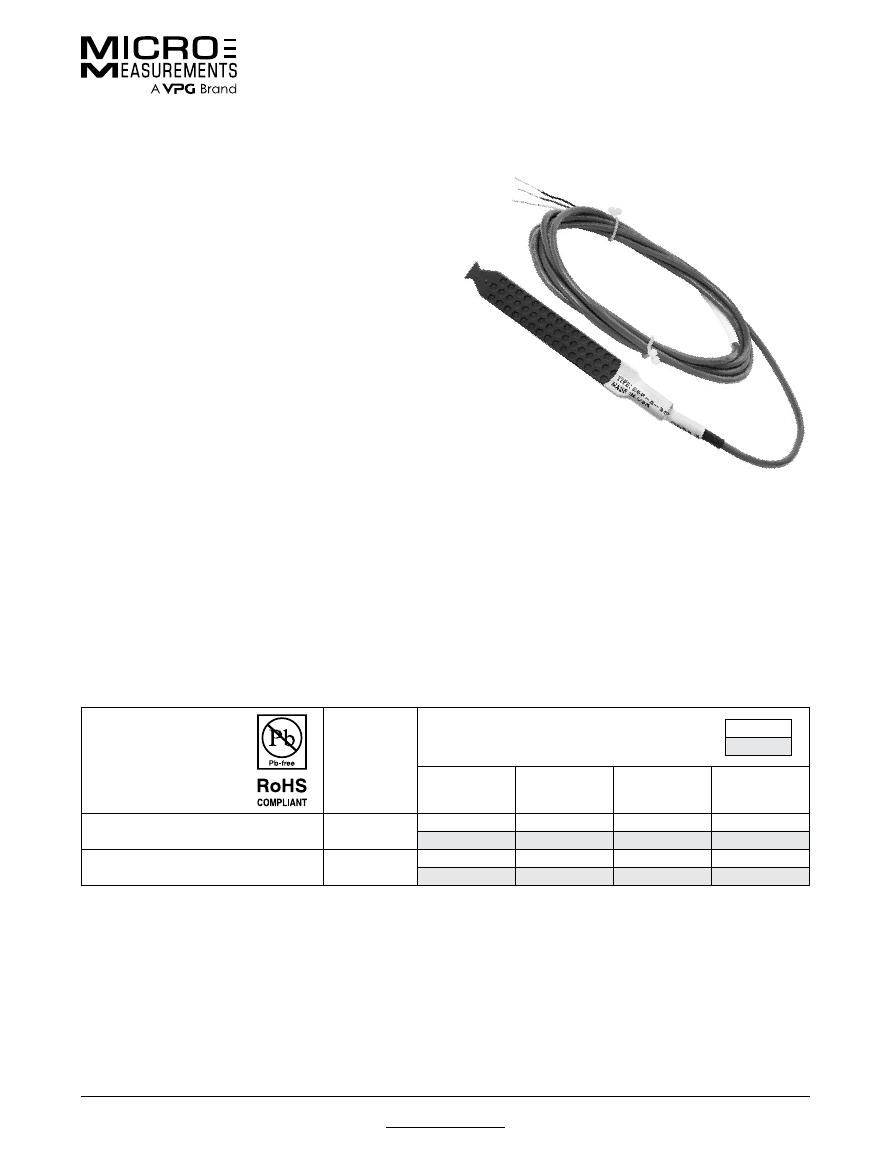
For technical questions, contact
mm@vpgsensors.com
Document No.: 11526
Revision: 15-Nov-2015
www.micro-measurements.com
133
Concrete Embedment Gages
Special Use Sensors—Concrete Embedment Strain Gages
Special Use Sensors—Concrete Embedment Strain Gages
GAGE
DESIGNATION
RES. IN
OHMS
DIMENSIONS
Legend:
ES = Each Section
inch
millimeter
ACTIVE GAGE
LENGTH
OUTER BODY
WIDTH
OUTER BODY
LENGTH
OUTER BODY
THICKNESS
EGP-5-120
120 ± 0.8%
4
0.7
5
0.4
100
17
130
10
EGP-5-350
350 ± 0.8%
4
0.7
5
0.4
100
17
130
10
The EGP-Series Embedment Strain Gage is specially
designed for measuring mechanical strains inside
concrete structures. The sensing grid, constructed of a
nickel-chromium alloy (similar to Karma), has an active
gage length of 4 in (100 mm) for averaging strains in
aggregate materials. A rugged 5 in (130 mm) outer body
of proprietary polymer concrete resists mechanical
damage during pouring, minimizes reinforcement of
the structure, and provides protection from moisture
and corrosive attack. The grid, cast within the polymer
concrete to ensure maximum strain sensitivity, is self-
temperature-compensated to minimize thermal output
when installed in concrete structures. Each gage
incorporates a heavy-duty 10 ft (3 m) cable with 22-AWG
(0.643 mm dia.) leadwires; a three-wire construction to
the sensing grid helps minimize temperature effects in
the instrumentation leads. Special lengths of preattached
cable will be quoted upon request. Micro-Measurements
M-LINE accessory cable 322-DJV is available for adding
cable length in the field.
Rugged and reliable, EGP-Series Strain Gages are
available in both 120-ohm (EGP-5-120) and 350-ohm
(EGP-5-350) resistances.
SPECIFICATIONS
•
Construction:
Strain sensing grid cast in a sturdy,
water-resistant material.
•
Sensing Grid:
Nickel-chromium alloy on polyimide
backing. Active gage length of 4 in (100 mm) nominal.
Grid resistance of 120 or 350 ohms, ±0.8%.
•
Outer Body:
Proprietary polymer concrete. 5 x 0.7 x
0.4 in (130 x 17 x 10 mm) nominal.
•
Cable:
Three 10 ft (3 m) leads of 22-AWG (0.643 mm
dia.) stranded tinned copper in 0.015 in (0.4 mm)
thick PVC insulation. Nominal cable diameter of 0.2 in
(5 mm). (Other lengths quoted upon request.)
•
Temperature Range:
The normal usage range is +25°
to +125°F (–5° to +50°C). Extended range is –25° to
+150°F (–30° to +60°C).
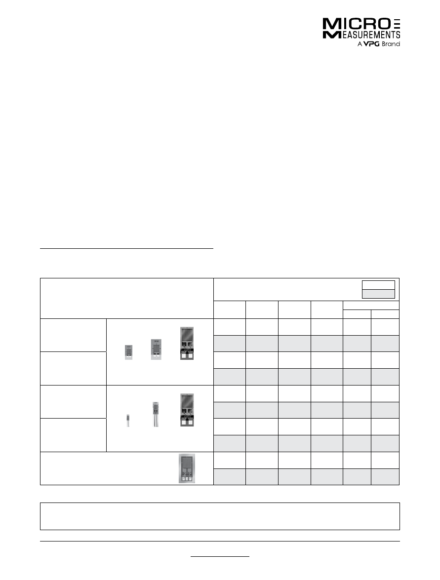
For technical questions, contact
mm@vpgsensors.com
www.micro-measurements.com
134
Document No.: 11522
Revision: 15-Nov-2015
Temperature Sensors and LST Networks
Special Use Sensors—Temperature
Special Use Sensors—Temperature
TG TEMPERATURE SENSORS
GAGE PATTERN AND DESIGNATION
Approximate Size Shown
See Note 1
DIMENSIONS
Legend:
SL = Shim Length; SW = Shim Width
inch
millimeter
GAGE
LENGTH
OVERALL
LENGTH
GRID
WIDTH
OVERALL
WIDTH
MATRIX
Length
Width
ETG-50A/Option E
ETG-50A/Option W
50B/E
50A/E
Opt W
Feature
0.060
0.148
0.100
0.100
0.28
0.20
1.52
3.76
2.54
2.54
7.0
4.8
ETG-50B/Option E
ETG-50B/Option W
0.125
0.235
0.125
0.125
0.33
0.19
3.18
5.97
3.18
3.18
8.3
4.7
WTG-50A
WTG-50A/Option W
50B
Opt W
Feature
50A
0.060
0.148
0.100
0.100
0.28
0.20
1.52
3.76
2.54
2.54
7.0
4.8
WTG-50B
WTG-50B/Option W
0.125
0.235
0.125
0.125
0.33
0.19
3.18
5.97
3.18
3.18
8.3
4.7
WWT-TG-W200B-050
For Weldable Temperature Sensor,
see appropriate datasheet.
0.20
0.71 SL
0.200
0.43 SW
0.52
0.26
5.08
18.03 SL
5.08
10.92 SW
13.1
6.6
Note 1:
Products with designations and options shown in bold are not RoHS compliant.
In addition to the standard line of temperature sensors described above, Micro-Measurements can furnish almost any
type of sensor pattern desired, in a wide range of resistances. Contact our Applications Engineering Department for
details.
Resistance thermometry is a widely employed method
of measuring temperature, and is based on using a
material whose resistivity changes as a function of
temperature. Resistance Temperature Detectors (RTD’s)
have fast response time, provide absolute temperature
measurement (since no reference junctions are involved),
and are very accurate. Their measurement circuits are
relatively simple, and the sensors, when properly installed,
are very stable over years of use.
Micro-Measurements resistance temperature sensors
are constructed much like wide-temperature-range
strain gages. The standard sensors utilize nickel or
nickel/manganin grids, although special-purpose gages
are also available in Balco
®
alloy or copper foil grids.
These temperature sensors are bonded to structures
using standard strain gage installation techniques,
and can measure surface temperatures from –452° to
approximately +500°F (–269° to +260°C). Because of their
extremely low thermal mass and the large bonded area,
the sensors follow temperature changes in the structural
mounting surface with negligible time lag.
Balco is a trademark of the W.B. Driver Company
TG TEMPERATURE SENSORS
TG Temperature Sensors are normally selected for
measurements from –320° to +500°F (–195° to +260°C).
The sensing grid utilizes a high purity nickel. Three basic
constructions are offered:
ETG Sensors have a polyimide carrier for flexibility. It is
available as an encapsulated gage with exposed solder
tabs (Option E), or with integral printed-circuit terminals
(Option W).
The WTG Sensor incorporates integral leadwires and a
high-temperature epoxy-phenolic matrix (reinforced with
glass fiber) which fully encapsulates the grid.
The WWT-TG Sensor is a slightly larger version of the
WTG, but preattached to a 0.005-in (0.13-mm) thick
stainless steel shim. This gage can be welded or bonded
to a structure.
The resistance at +75°F (+23.9°C) is 50Ω ±0.3% for the
ETG and WTG Sensors; and 50Ω ±0.4% for the WWT-TG
Sensors.
Maximum operating temperature for ETG Sensors with
Option E is +450°F (+230°C), and +350°F (+175°C) for
Option W. All other types are +500°F (+260°C).
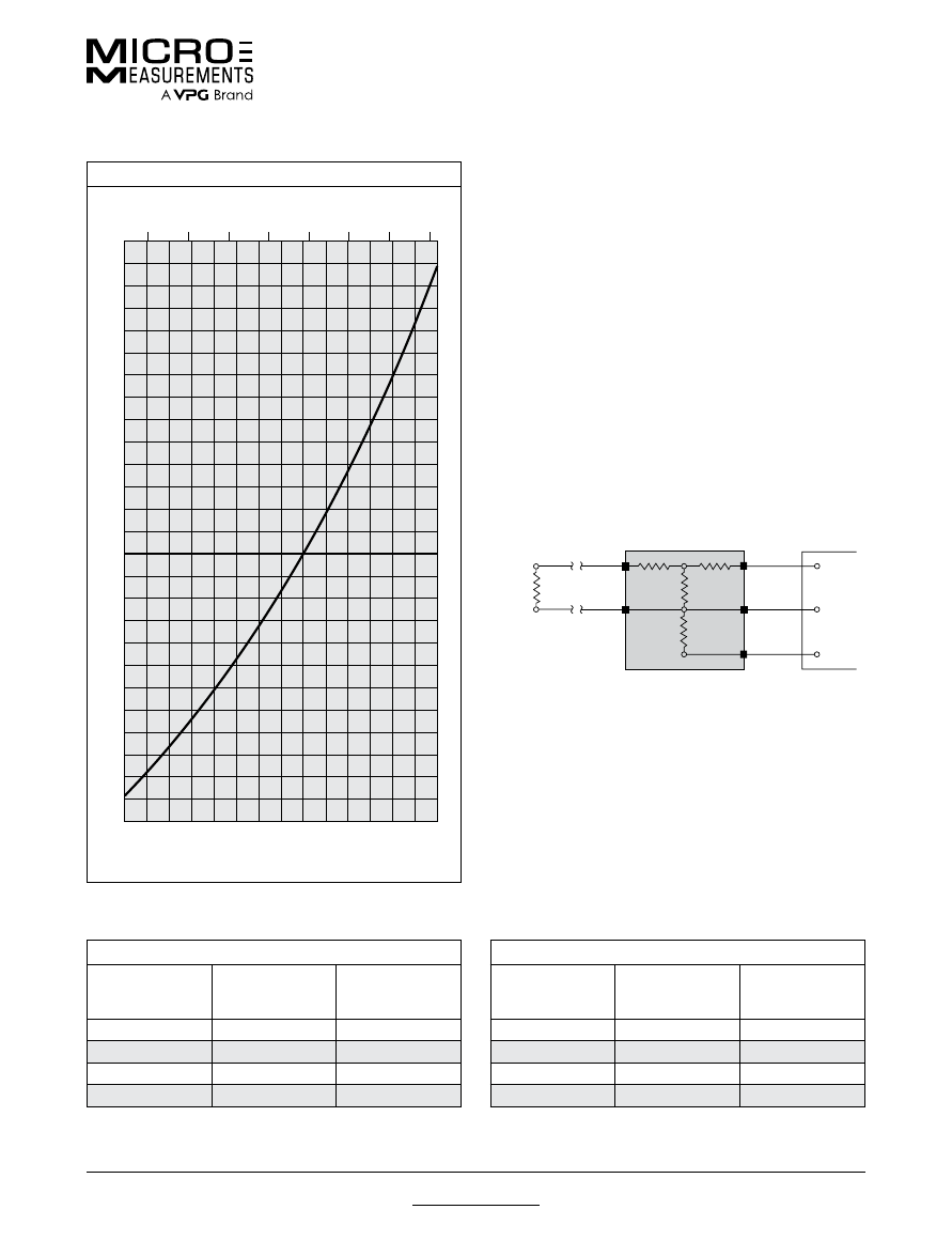
For technical questions, contact
mm@vpgsensors.com
Document No.: 11522
Revision: 15-Nov-2015
www.micro-measurements.com
135
Temperature Sensors and LST Networks
Special Use Sensors—Temperature
TG LST MATCHING NETWORKS
The temperature coefficient of resistance of nickel sensors
is very high but nonlinear as indicated in the graph.
The sensor resistance can be measured directly and
converted to temperature with the charts supplied in Tech
Note TN-506, but since TG Sensors are commonly used
along with strain gages, special matching networks have
been developed to use with strain gage instrumentation.
These LST Matching Networks are small passive
devices encapsulated in a molded epoxy case. They
are connected between TG Temperature Sensors and
the strain gage readout instrumentation to perform the
following three functions:
1. Linearize the gage resistance versus temperature.
2. Attenuate the resistance change slope to the equivalent
of 10 or 100 microstrain per degree F or C for a gage
factor setting of 2.000 on the strain indicator.
3. Present a balanced 350-ohm half-bridge circuit to the
strain indicator at the reference temperature of 0°F
(Fahrenheit networks) or 0°C (Celsius networks).
In order to optimize performance, separate network
designs are available for cryogenic and normal
temperature ranges. Environmental temperature range
of LST networks is –65° to +250°F (–55° to +125°C).
Standard strain gage instrumentation, such as the
Micro-Measurements Model P3, is ideal for use with
these sensors, eliminating the need to purchase separate
readout devices.
TG
Sensor
50
Ω
@ +75 F
(+23.9 C)
3
2
1
5
4
LST NETWORK
Active
Dummy
Strain Indicator
LOW TEMPERATURE RANGE
NETWORK
DESIGNATION
OUTPUT
SLOPE
SENSOR
TEMPERATURE
RANGE
LST-10F-350C
10 microstrain/°F
–320° to +100°F
LST-10C-350C
10 microstrain/°C
–200° to +25°C
LST-100F-350C
100 microstrain/°F
–320° to +100°F
LST-100C-350C
100 microstrain/°C
–200° to +25°C
NORMAL TEMPERATURE RANGE
NETWORK
DESIGNATION
OUTPUT
SLOPE
SENSOR
TEMPERATURE
RANGE
LST-10F-350D
10 microstrain/°F
–200° to +500°F
LST-10C-350D
10 microstrain/°C
–150° to +260°C
LST-100F-350D
100 microstrain/°F
–200° to +500°F
LST-100C-350D
100 microstrain/°C
–150° to +260°C
TYPICAL DATA FOR 50 Ω NICKEL SENSOR
Temperature in °C
Temperature in °F
Typical data for 50 Ω nickel sensor.
–200 –100
0
+100 +200 +300 +400
+500
–100
0
+100
+200
140
130
120
110
100
90
80
70
60
50
40
30
20
10
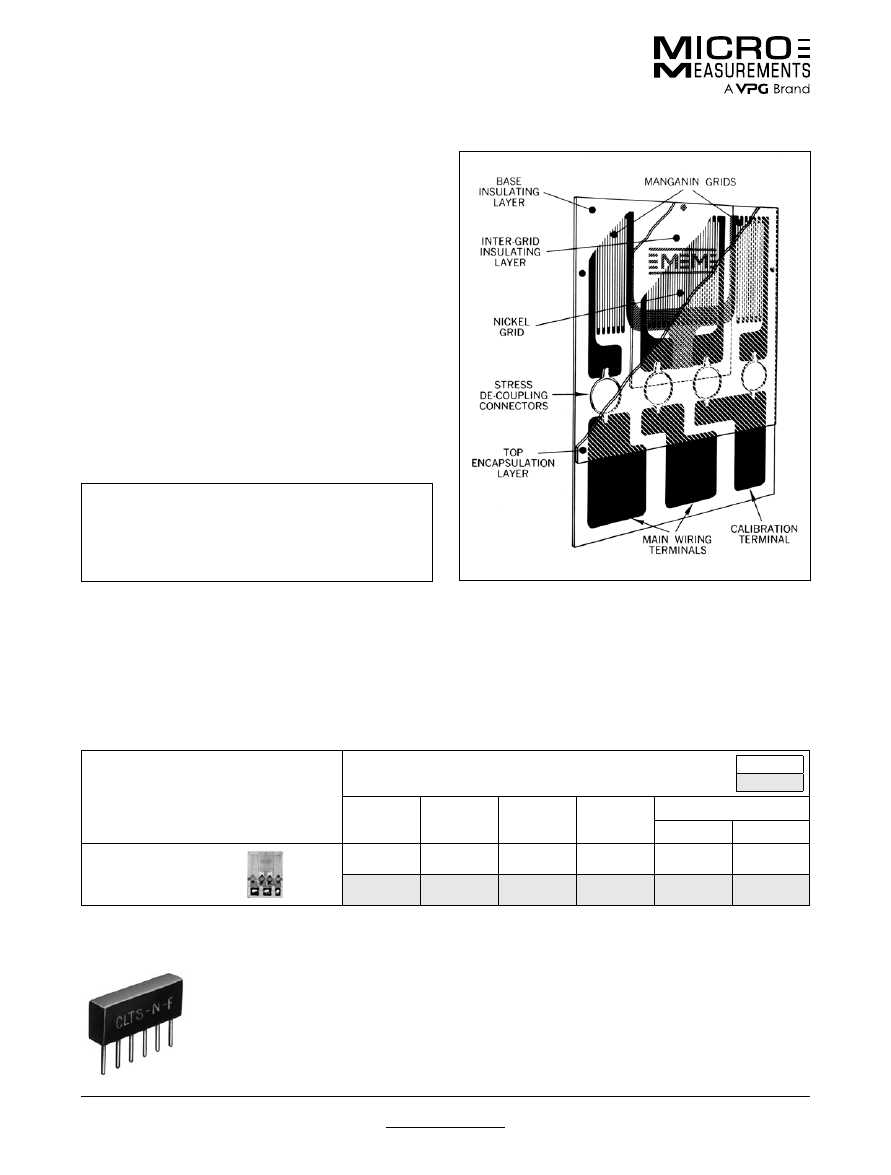
For technical questions, contact
mm@vpgsensors.com
www.micro-measurements.com
136
Document No.: 11522
Revision: 15-Nov-2015
Temperature Sensors and LST Networks
Special Use Sensors—Temperature
CLTS-2B TEMPERATURE SENSORS
The Cryogenic Linear Temperature Sensor (CLTS) is
recommended for best accuracy over the temperature
range of –452° to +100°F (–269° to +40°C). The CLTS-2B
is a small surface thermometer gage consisting of two thin
foil sensing grids laminated into a glass-fiber-reinforced
epoxy-phenolic matrix, and electrically wired in series.
The two alloys are special grades of nickel and manganin
that are processed for equal and opposite nonlinearities
in resistance versus temperature characteristics. The
CLTS-2B is fabricated with integral printed-circuit
terminals to provide strong, convenient attachment points
for the leadwires. Gage construction is illustrated at right.
Because of its low thermal mass and thin construction,
the CLTS-2B responds quickly and accurately to
temperature changes in the surface to which it is bonded.
Special design features protect the sensor from damage
due to thermal shock, even during plunges from room
temperature directly into liquefied gases, including LHe at
–452°F (–269°C).
Avoid prolonged exposure of the CLTS-2B to temper-
atures above +150°F (+65°C) as this may adversely
affect characteristics of the manganin material. The
maximum recommended curing temperature of the
bonding adhesive is two hours at +200°F (+95°C).
CLTS-2B SENSITIVITY
The nominal resistance of the CLTS-2B is 290.0 ohms
±0.5% at +75°F (+23.9°C). The resistance decreases
linearly with temperature, reaching a nominal value of
220.0 ohms at –452°F (–269°C). This represents a change
of 70 ohms for 527°F, or a slope of 0.1328 ohms per
degree F; the corresponding slope on the Celsius scale is
0.2391 ohms per degree C. With proper instrumentation
a resolution of 0.01° can be easily achieved. Data readout
can be accomplished by directly monitoring resistance
change with an appropriate resistance measuring
instrument.
GAGE PATTERN
AND DESIGNATION
Actual size shown
DIMENSIONS
inch
millimeter
GAGE
LENGTH
OVERALL
LENGTH
GRID
WIDTH
OVERALL
WIDTH
MATRIX
Length
Width
CLTS-2B
0.130 ES
0.205
0.280 ES
0.280
0.43
0.31
3.30 ES
5.21
7.11 ES
7.11
10.9
7.9
CLTS MATCHING NETWORKS
When used in conjunction with
bonded strain gages, it is often
most convenient to modify the
CLTS output with a simple, passive
resistance network that can be used
with strain gage instrumentation as
described with the TG Sensors. The
sensitivity can be adjusted to 10 microstrain per degree
C (CLTS-N-C); with a resolution of 0.1° when used with
most strain indicators. This type of network also provides
a high degree of leadwire compensation. Environmental
temperature limits for CLTS Networks are –65° to +250°F
(–55° to +125°C).
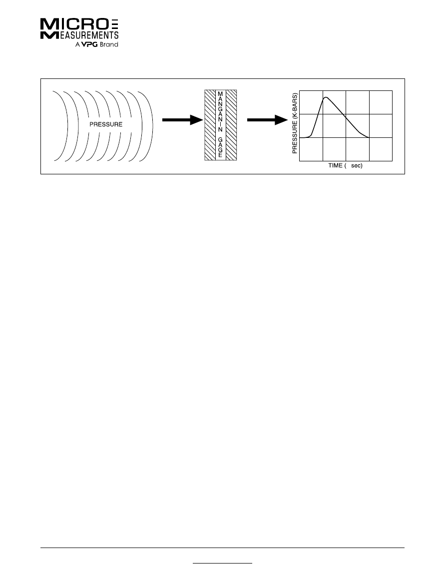
For technical questions, contact
mm@vpgsensors.com
Document No.: 11524
Revision: 15-Nov-2015
www.micro-measurements.com
137
Manganin Patterns
Special Use Sensors—Manganin Pressure Sensor
Special Use Sensors—Manganin Pressure Sensor
Manganin is a copper-manganese-nickel alloy with a
low strain sensitivity, but a relatively high sensitivity to
hydrostatic pressure. Resistance change as a function
of applied pressure is linear to extremely high pressures.
This characteristic has been utilized in the construction
of high-range fluid pressure cells using manganin wire for
many years.
Manganin gages are used extensively in high-pressure
shock wave studies ranging from 1 to over 400 kilobars
(1 bar = 14.5 psi = 100 000 N/m
2
). In conventional
applications, the gage is bonded between two flat metallic
or polymer plates.
Micro-Measurements offers a large selection of gages for
shock wave studies, manufactured from specially treated
shunt stock manganin foil. The ultrathin construction
offers several advantages over the wire type, including:
• Improved repeatability from gage to gage, due to
precisely defined grids manufactured from the same lot
of foil.
• Faster response times (nanosecond rise times have
been recorded).
• Smaller, high resistance grids.
• Minimal distortion of the pressure wave when mounted
in high-modulus materials.
TECHNICAL INFORMATION
Nominal pressure sensitivity of Micro-Measurements
manganin foil gages is 0.27% per kilobar (0.0027
ohm/ohm/kb). Long signal transmission cables, low
signal levels, and high electrical noise complicate
the measurement. Most of these gages are designed
for impedance matching to 50-ohm coaxial cable.
The 210AW pattern illustrated has been used with
excitation currents exceeding 6 amperes for periods to
100 microseconds.
The 580SF pattern was designed specifically for
investigating the effects of sweeping explosive waves.
With the target intentionally tilted at a small angle to the
wave front, the pressure wave traverses the grid in the
direction toward the leads.
Micro-Measurements manufactures manganin foil gages
in several backing materials. The backing material is
normally selected to minimize the mechanical impedance
mismatch within the target.
L backing
is a glass-fiber-reinforced epoxy-phenolic
approx. 0.002 in (0.050 mm) thick. Although commonly
used in the 1- to 15-kilobar range, its usefulness is not
limited to this extent. The backing is ideal for use in
quartz-phenolic transducers since it does not present a
significant impedance discontinuity. L-backed gages may
be used in high-mechanical-impedance materials with the
understanding that rise-time limitations may exist due to
an impedance mismatch between the sensor and the test
material. An encapsulated version (Option SP60), with
only the tab ends exposed for soldering, is available.
N2 backing
is nominally 0.0008 in (0.020 mm) thick
polyimide film. This backing is rugged, highly flexible, and
easy to handle. It is suited to very-low-kilobar pressure
ranges.
J2 backing
is an encapsulated version of the N2, with the
ends of the tabs exposed.
µ
FOR HIGH-PRESSURE MEASUREMENTS
SHOCK WAVE PROPAGATION • BLAST EFFECT • EXPLOSIVE-FORMING STUDIES
HIGH HYDROSTATIC PRESSURES
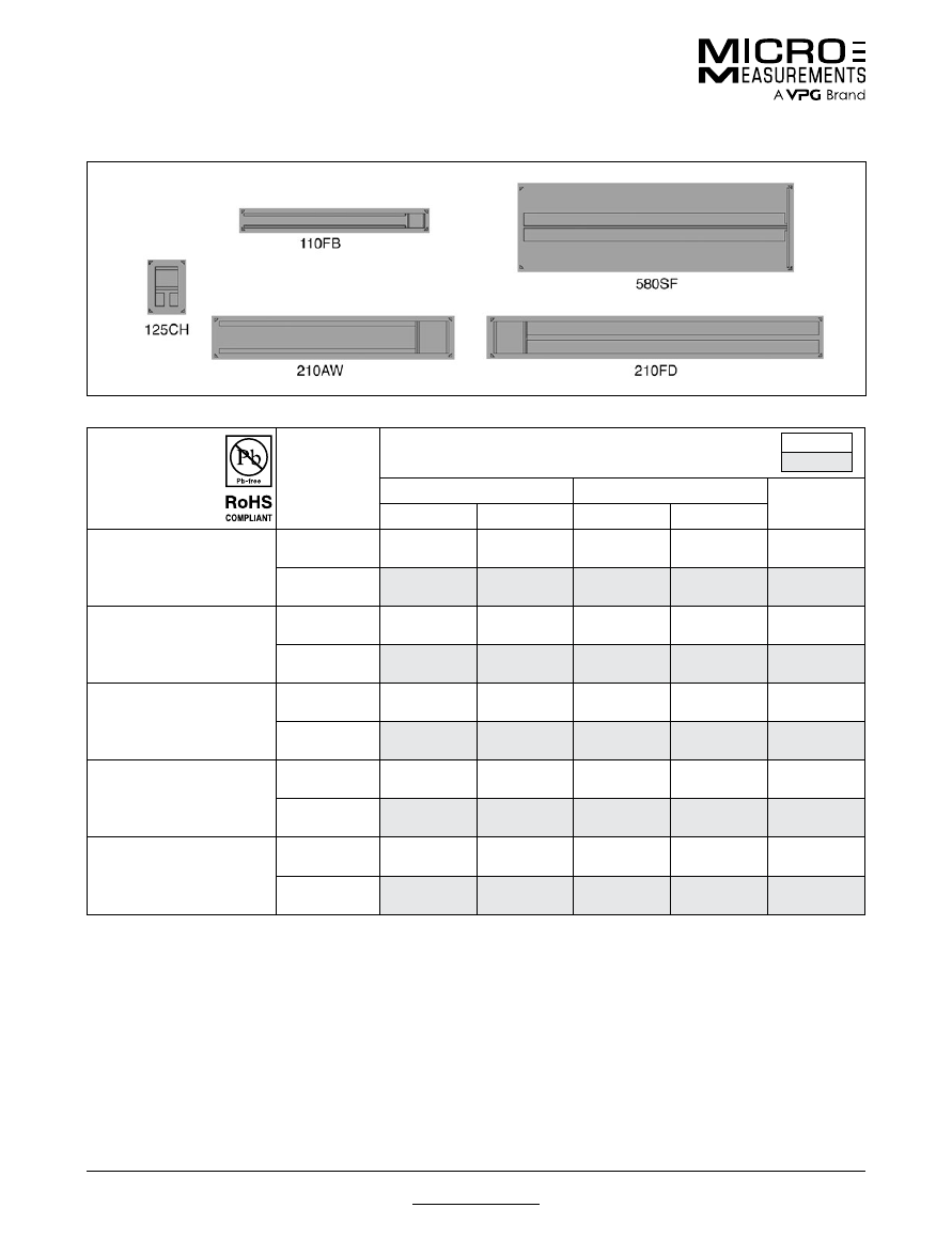
For technical questions, contact
mm@vpgsensors.com
www.micro-measurements.com
138
Document No.: 11524
Revision: 15-Nov-2015
Manganin Patterns
Special Use Sensors—Manganin Pressure Sensor
GAGE
DESIGNATION
FOIL
THICKNESS
DIMENSIONS
inch
millimeter
OVERALL PATTERN
ACTIVE GRID
TAB LENGTH
Length
Width
Length
Width
LM-SS-110FB-048
LM-SS-110FB-048/SP60
N2M-SS-110FB-048
J2M-SS-110FB-048
0.0002
1.380
0.125
0.110
0.125
1.240
0.005
35.05
3.18
2.79
3.18
31.49
LM-SS-125CH-048
LM-SS-125CH-048/SP60
N2M-SS-125CH-048
J2M-SS-125CH-048
0.0002
0.290
0.175
0.125
0.175
0.100
0.005
7.37
4.45
3.18
4.45
2.54
LM-SS-210AW-048
LM-SS-210AW-048/SP60
N2M-SS-210AW-048
J2M-SS-210AW-048
0.0005
1.750
0.250
0.210
0.250
1.500
0.013
44.45
6.35
5.33
6.35
38.10
LM-SS-210FD-050
LM-SS-210FD-050/SP60
N2M-SS-210FD-050
J2M-SS-210FD-050
0.0005
2.500
0.250
0.210
0.250
2.250
0.013
63.50
6.35
5.33
6.35
57.15
LM-SS-580SF-025
LM-SS-580SF-025/SP60
N2M-SS-580SF-025
J2M-SS-580SF-025
0.0004
2.018
0.600
0.580
0.008
2.000
0.010
51.26
15.24
14.73
0.20
50.80
† All resistance values are ±1%, measured on the tab near the grid.

For technical questions, contact
mm@vpgsensors.com
Document No.: 11520
Revision: 15-Nov-2015
www.micro-measurements.com
139
Crack Detection Patterns
Special Use Sensors—Crack Detection Sensors
Special Use Sensors—Crack Detection Sensors
For repetitive use on identical structural shapes, special patterns may be designed to fit the expected crack
formation area. Contact our Applications Engineering Department for details.
CD-Series Crack Detection Gages are designed to
provide a convenient, economical method of indicating
the presence of a crack, or indicating when a crack has
progressed to a predetermined location on a test part
or structure. By employing several CD gages, it is also
possible to monitor the rate of crack growth; however,
Crack Propagation Gages would normally be selected for
that purpose.
In some applications, thin copper wires bonded to the
test structure are used to provide a low-cost method of
detecting crack initiation or propagation. Because of the
behavior of copper wire, however, this method suffers
from two limitations: (a) the crack tip may progress
considerably beyond the wire without breaking the strand,
and (b) in areas of high cyclic strains, the wire may fail in
fatigue without crack initiation in the specimen. CD-Series
Crack Detection Gages are designed to overcome both of
these limitations.
CD-Series gages consist of a single strand of high-
endurance alloy. A crack propagating beneath the gage
will induce local fracture of the sensing strand and open
the electrical circuit. When the CD gage is installed at
critical locations on a test part or structure and used as a
sensing element in a control system, the signal can serve
to alter a test sequence or to alert an operator to incipient
component failure.
CONSTRUCTION
Two gage constructions are currently available:
The CD-02 is made of beryllium copper alloy laminated to
polyimide, and offers a low-resistance sensing element.
Select the CD-02 type for maximum conformability to
irregular surfaces and ease of soldering, when greatest
fatigue life is not required.
The CD-23 type is constructed of isoelastic alloy
laminated to a glass-fiber-reinforced backing for
applications where the highest endurance is required.
The superior fatigue life of the isoelastic alloy allows
the CD-23 to be used in high cyclic strain fields without
premature failure, while maintaining high sensitivity
to crack formation under the gage. This gage is less
conformable than the CD-02 and requires use of SS-Flux
for tinning of solder tabs for leadwire attachment.
Crack Detection Gages are available with various strand
lengths; from 0.4 in (10 mm) for applications where space
is limited, to 2.0 in (50 mm) for use where the direction
of crack propagation, or the point of crack initiation, is
uncertain.
Resistance of the CD Series is nominally 0.05Ω/mm of
active strand length for beryllium copper and 1Ω/mm for
isoelastic gages.
The normal operating temperature range is –320° to
+250°F (–195° to +120°C).
ADHESIVES
Conventional strain gage adhesives are suitable for
bonding CD-Series gages. M-Bond 600, 610, or 43-B
are preferred for excellent performance over the widest
operating temperature range. However, M-Bond
AE-10 and AE-15 are also suitable where in-service
temperatures will not exceed +200°F (+95°C). M-Bond
200 is satisfactory for fast installation, but should not be
used for long-term testing.
PROTECTIVE COATINGS
Corrosion, which can cause premature filament failure, is
greatly accelerated in the presence of high cyclic strain
fields. For long-term use, it is essential to protect the
crack detection gage from atmospheric corrosion and
other contamination.
M-Bond 43-B is an excellent protective coating when
the bonding adhesive, leadwire insulation and solder can
tolerate the cure temperature. If lower cure temperatures
are necessary, M-Bond AE-10 and AE-15 are
recommended. When in-service environmental conditions
are not extreme, a softer coating may prove perfectly
adequate. Either 3140 RTV or M-Coat D would be a good
choice in these instances.
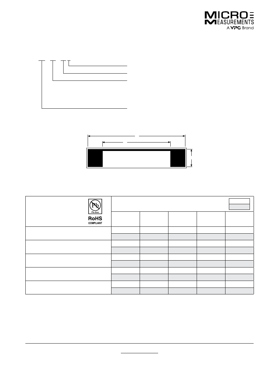
For technical questions, contact
mm@vpgsensors.com
www.micro-measurements.com
140
Document No.: 11520
Revision: 15-Nov-2015
Crack Detection Patterns
Special Use Sensors—Crack Detection Sensors
GAGE DESIGNATION
DIMENSIONS
inch
millimeter
a
b
c
LENGTH
WIDTH
CD-02-10A
CD-23-10A
0.40
0.56
0.10
0.60
0.13
10.2
14.2
2.5
15.2
3.2
CD-02-15A
CD-23-15A
0.60
0.76
0.10
0.80
0.13
15.2
19.3
2.5
20.3
3.2
CD-02-20A
CD-23-20A
0.80
0.96
0.10
1.00
0.13
20.3
24.4
2.5
25.4
3.2
CD-02-25A
CD-23-25A
1.00
1.16
0.10
1.20
0.13
25.4
29.5
2.5
30.5
3.2
CD-02-50A
CD-23-50A
2.00
2.16
0.10
2.22
0.13
50.8
54.9
2.5
56.4
3.2
a
b
c
C D – 2 3 – 1 5 A
GEOMETRY
(tabs as shown)
LENGTH OF ACTIVE LINE IN MILLIMETERS
MATERIAL AND CONSTRUCTION:
02 = 0.0005 in (0.013 mm) beryllium copper laminated to
0.001 in (0.025 mm) polyimide backing
23 = 0.00025 in (0.006 mm) isoelastic alloy laminated to
0.0008 in (0.020 mm) glass-fiber-reinforced backing
CRACK DETECTION GAGE
(single strand)
CD-SERIES GAGE DESIGNATION
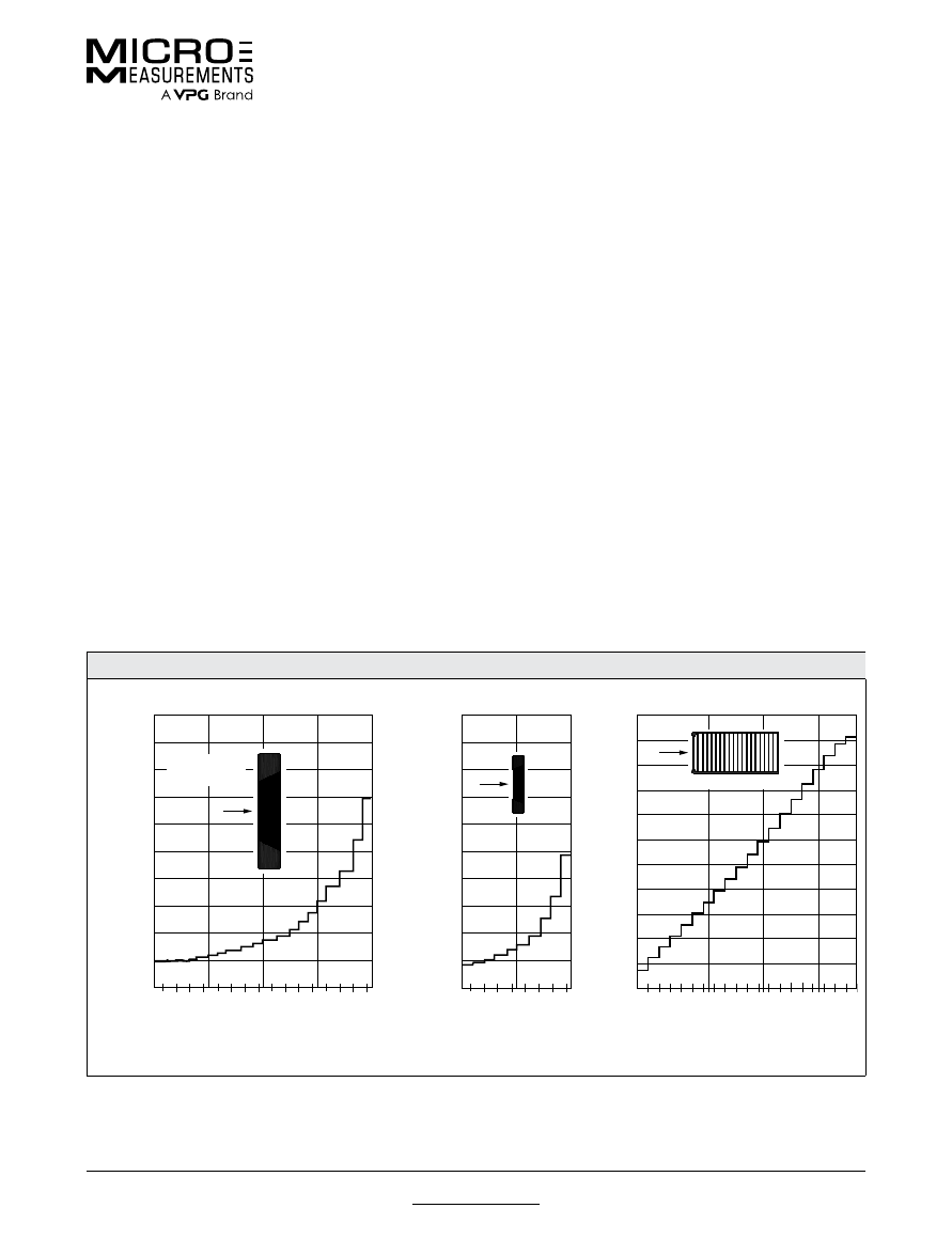
For technical questions, contact
mm@vpgsensors.com
Document No.: 11521
Revision: 15-Nov-2015
www.micro-measurements.com
141
Crack Propagation Patterns
Special Use Sensors—Crack Propagation Sensors
Special Use Sensors—Crack Propagation Sensors
Crack Propagation Gages provide a convenient method
for indicating rate of crack propagation in a test part or
structure. The CPA, CPB, and CPC patterns consist of a
number of resistor strands connected in parallel. When
bonded to a structure, progression of a surface crack
through the gage pattern causes successive open-
circuiting of the strands, resulting in an increase in total
resistance. The CPA pattern incorporates 20 resistor
strands; the CPB, with the same basic configuration,
incorporates ten. Both series produce stepped increases
in resistance with successive open-circuiting as indicated
in the charts below. In applications where space permits,
the CPC pattern may be preferred because of greater
uniformity of increases in total resistance with successive
strand fractures.
The resistor strands of the CPD pattern operate
independently, each producing an open circuit when
fractured. This type of gage allows the user to electrically
predetermine a specific point in the fracturing process
at which the instrumentation will perform some type of
altering function.
GAGE CHARACTERISTICS
Crack Propagation Gages have a nominal gage thickness
of only 0.0017 in (0.043 mm). The high-endurance
K-alloy foil grid has a single cycle strain range of up to
±1.5% with a fatigue life of greater than 10
7
cycles at
±2000 microstrain. The standard backing is a glass-fiber-
reinforced epoxy matrix. These gages are useful through
the temperature range of –452°F (–269°C) to over +450°F
(+230°C).
Since exact self-temperature compensation is
unnecessary in crack propagation studies, all of these
gages are supplied in 09 S-T-C.
Crack Propagation Gages feature small copper pads on
the tabs for ease of soldering.
ADHESIVES AND PROTECTIVE COATINGS
Crack Propagation Gages should be installed with
a solvent-thinned adhesive incorporating a cure
temperature of at least +300°F (+150°C). M-Bond 600 or
610 adhesives are recommended for use over the widest
temperature range. Handling tape should not be applied
over the grid or soldering tabs during installation. Room-
temperature-curing adhesives are not recommended for
use with Crack Propagation Gages.
Protective coating selection considerations are similar
to those for CD-Series Crack Detection Gages.
Refer to appropriate datasheet for protective coating
recommendations.
GAGE RESISTANCE CHARTS
—See circuitry on following page
0
5
10
15
20
25
30
35
40
45
50
55
0
5
10
15
RESISTANCE – OHMS
STRANDS FRACTURED
CPC03
P
(1/2 size)
0
5
10
15
20
25
30
35
40
45
50
0
5
15
20
RESISTANCE – OHMS
(WITH 50Ω SHUNT)
STRANDS FRACTURED
CPA01 & CPA02
Direction of
Propagation
P
0
5
10
15
20
25
30
35
40
45
50
0
5
10
RESISTANCE – OHMS
(WITH 50Ω SHUNT)
STRANDS FRACTURED
CPB02
P
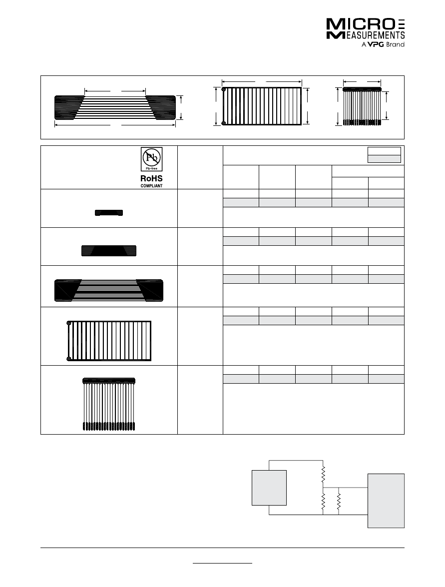
For technical questions, contact
mm@vpgsensors.com
www.micro-measurements.com
142
Document No.: 11521
Revision: 15-Nov-2015
Crack Propagation Patterns
Special Use Sensors—Crack Propagation Sensors
GAGE DESIGNATION
AND DESIGNATION
NOMINAL
RESISTANCE
IN OHMS
DIMENSIONS
inch
millimeter
a
b
c
MATRIX
Length
Width
TK-09-CPB02-005/DP
5
0.25
0.50
0.10
0.56
0.16
6.4
12.7
2.5
14.2
4.1
Ten grid lines—0.010 in (0.25 mm) between centerlines.
TK-09-CPA01-005/DP
5
0.50
1.00
0.20
1.08
0.28
12.7
25.4
5.1
27.4
7.1
Twenty grid lines—0.010 in (0.25 mm) between centerlines.
TK-09-CPA02-005/DP
5
1.00
2.00
0.40
2.08
0.48
25.4
50.8
10.2
52.8
12.2
Twenty grid lines—0.020 in (0.51 mm) between centerlines.
TK-09-CPC03-003/DP
3
0.70
0.75
1.57
0.80
1.62
17.8
19.1
39.9
20.3
41.1
Twenty grid lines—0.080 in (2.03 mm) between centerlines.
TK-09-CPD01-NRA/DP
110
0.75
1.00
1.00
1.11
1.11
19.1
25.4
25.4
28.1
28.1
Twenty grid lines—0.050 in (1.27 mm) between centerlines.
c
b
a
CPA, CPB
c
a
CPC
b
c
a
CPD
b
CIRCUITRY
CPA, CPB, AND CPC PATTERNS
An ohmmeter with milliohm sensitivity is a suitable readout
instrument. Alternately, a strip chart recorder, connected in the
manner shown at right, can be used to obtain a step curve of
strands broken versus time.
CPD PATTERN
Low voltage instrumentation can be employed to shut off a motor,
sound an alarm, or trigger some other type of alerting function.
50
Ω
–
STRIP
CHART
RECORDER
10 mV
RANGE
15 Vdc
POWER
SUPPLY
Crack
Propagation
Gage
+
–
+
100K
Ω
1% WW
Conventional strain gage instrumentation is not readily adaptable for use with Crack Propagaton Gages.
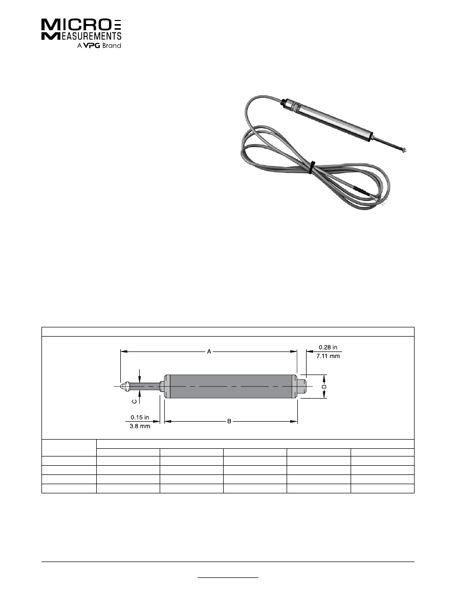
For technical questions, contact
mm@vpgsensors.com
Document No.: 11350
Revision: 03-Feb-2016
www.micro-measurements.com
143
Linear Displacement Sensors
Special Use Sensors—Linear Displacement Sensors
Special Use Sensors—Linear Displacement Sensors
FEATURES
• Infinite resolution
• True output linearity over the entire measurement range
• Low operating forces
• Excellent stability and temperature compensation
DESCRIPTION
Micro-Measurements Linear Displacement Sensors use a
fully active 350-ohm strain-gage bridge to sense spindle
displacement, giving infinite resolution and excellent
linearity. They are compatible with all standard strain-gage
instrumentation with bridge excitation from 2 to 10 volts.
With a selection of models having full-scale ranges from
1/4 in (5 mm) to 4 in (100 mm), Linear Displacement
Sensors feature a unique design that produces maximum
operating forces of less than 1 lb (4.4 N). Available
with specially designed mounting fixtures, these
versatile sensors are ideally suited for use in research,
manufacturing and process control applications.
ACCURACY
Micro-Measurements Linear Displacement Sensors
produce an output voltage proportional to a captive,
guided spindle displacement by means of a 350-ohm
strain gage bridge with four active arms. This arrangement
provides excellent temperature compensation and
linearity.
COMPATIBILITY
Micro-Measurements Linear Displacement Sensors
exhibit the same inherent advantages for linearity,
versatility and precision as many other strain-gage-based
sensors. As such, they are systems-compatible with a
wide range of commonly used sensors for pressure, load,
acceleration, vibration, etc. and normally utilize the same
instrumentation.
OUTLINE DIMENSIONS
in inches (millimeters)
(
)
(
)
DIMENSION
MODEL
HS5
HS10
HS25
HS50
HS100
A
4.10 in (104.2 mm)
4.30 in (109.2 mm)
5.44 in (138.2 mm)
8.48 in (215.4 mm)
14.97 in (380.2 mm)
B
3.49 in (88.6 mm)
3.49 in (88.6 mm)
4.08 in (103.6 mm)
6.11 in (155.2 mm)
10.47 in (266.0 mm)
C
∅
0.19 in (4.8 mm)
0.19 in (4.8 mm)
0.19 in (4.8 mm)
0.19 in (4.8 mm)
0.24 in (6.0 mm)
D
∅
0.69 in (17.4 mm)
0.69 in (17.4 mm)
0.69 in (17.4 mm)
0.69 in (17.4 mm)
1.0 in (25.4 mm)
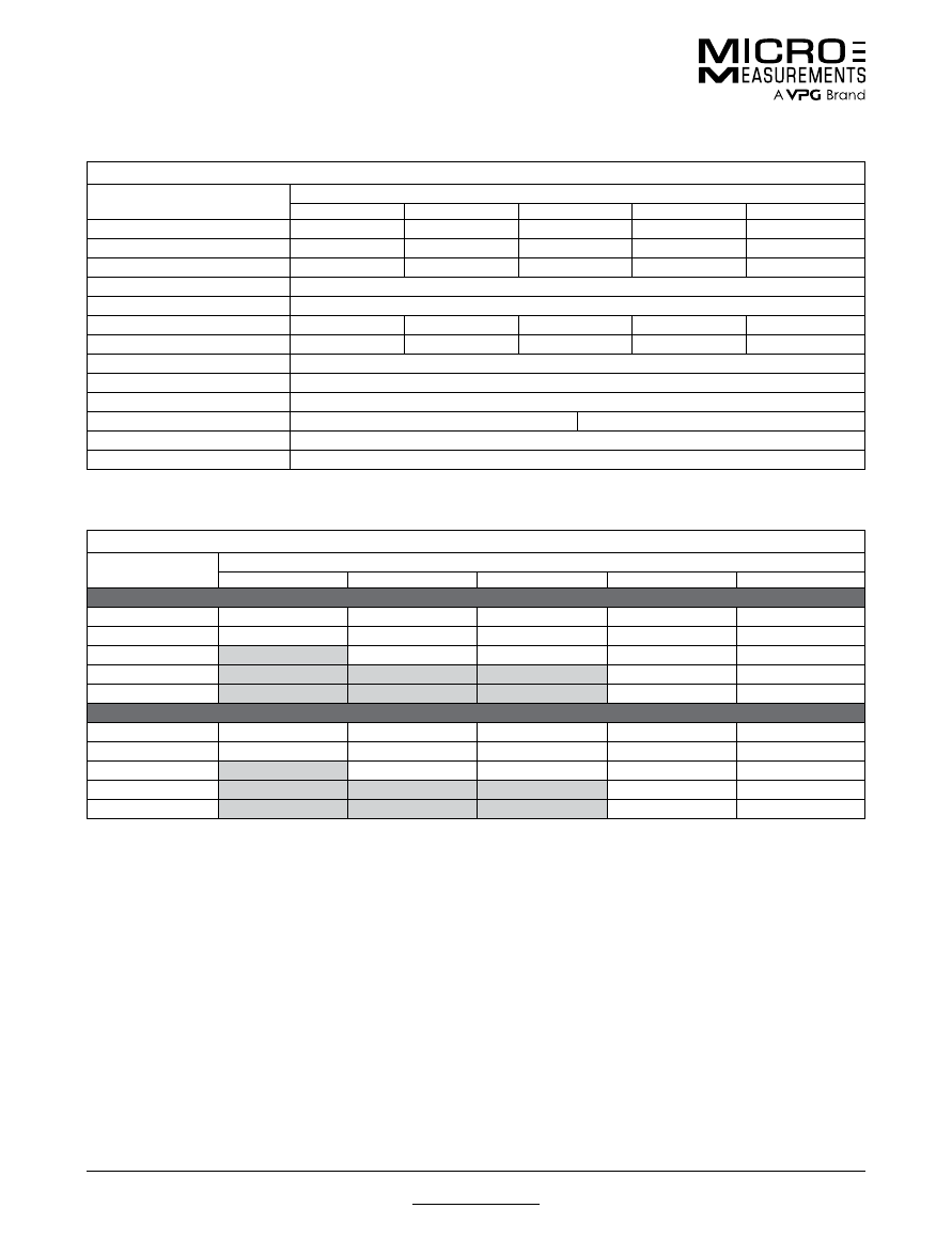
For technical questions, contact
mm@vpgsensors.com
www.micro-measurements.com
144
Document No.: 11350
Revision: 03-Feb-2016
Linear Displacement Sensors
Special Use Sensors—Linear Displacement Sensors
FATIGUE LIFE
MODEL
DISPLACEMENT (NCHES)
0.25
0.50
1.00
2.00
4.00
Cycles to Failure (Nominal)
HS5
5.00E+04
HS10
5.00E+05
5.00E+04
HS25
5.00E+06
5.00E+05
5.00E+04
HS50
5.00E+06
5.00E+06
5.00E+06
5.00E+05
HS100
5.00E+06
5.00E+06
5.00E+06
5.00E+05
5.00E+04
Signal (mV/V)
HS5
4.50
HS10
2.65
5.30
HS25
1.75
3.50
7.00
HS50
0.45
0.90
1.80
3.60
HS100
0.32
0.65
1.30
2.60
5.20
* Please note that recommended displacements are indicated by shading
SPECIFICATIONS
PARAMETERS
MODEL
HS5
HS10
HS25
HS50
HS100
Displacement Range*
0.25 in (6.5 mm)
0.5 in (11.2 mm)
1 in (26 mm)
2 in (51.5 mm)
4 in (102 mm)
Weight
0.31 lb (140 g)
0.31 lb (140 g)
0.33 lb (150 g)
0.44 lb (200 g)
1.10 lb (500 g)
Spring Force*
0.44 lb (200 g)
0.55 lb (250 g)
0.55 lb (250 g)
0.66 lb (300 g)
0.77 lb (350 g)
Excitation
2 to 10 V, AC or DC
Frequency Response*
5-mm displacement: 100 Hz; 100-mm displacement: 10 Hz
Rated (F.S.) Output*
4.5 mV/V
5.3 mV/V
7.0 mV/V
3.6 mV/V
5.2 mV/V
Nonlinearity (Best-Fit Method)*
0.35% FS
0.35% FS
0.35% FS
0.35% FS
0.35% FS
Resolution
Infinite
Bridge Resistance (Nominal)
350 ohms bridge, 100k ohms zero balance
Temperature Range
+15 to +140°F (–10 to +60°C)
Temperature Coefficient (%FS)*
Zero <0.006%/°F (<0.01%/°C)
Span <0.006%/°F (<0.01%/°C)
Termination
0.18 in PVC 7/0.008 (4.5 mm PVC 7/0.2), 4-core shielded, 6.6 ft (2.2 m) long
Electrical Connections
Input: Red+ Black– ; Output: Green+ White–
* Typical figures: actual values subject to calibration
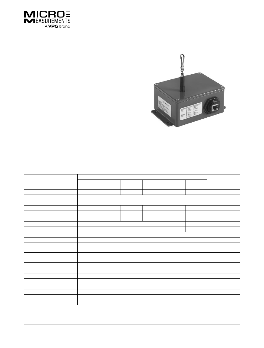
For technical questions, contact
mm@vpgsensors.com
Document No.: 11004
Revision: 15-Nov-2015
www.micro-measurements.com
145
Cable-Extension Displacement Sensor
Special Use Sensors—Cable-Extension Displacement Sensors
Special Use Sensors—Cable-Extension Displacement Sensors
FEATURES
• Full-scale ranges from 5 to 50 inches
• Rugged, low profile design
• Switch-selectable potentiometer and Wheatstone
bridge output circuits
• Standard RJ-45 electrical connections
• Compatible with all Micro-Measurements strain gage
and high-level-signal instrumentation
• Easy to install and use
DESCRIPTION
The Micro-Measurements Cable-Extension Displacement
Sensor provides a voltage signal linearly proportional to
the extension of a retractable stainless steel cable. Used
for indicating the displacement of the test structure,
member or part to which the cable is attached, installation
is quick and easy. Simply attach the base of the sensor
to a reference surface, the cable to the component being
displaced, and the electrical leads to any instrument
accepting strain-gage or high-level signal inputs. With the
certified calibration data and wiring instructions provided
with each sensor, you will be making displacement
measurements in minutes.
SPECIFICATIONS
PARAMETER
MODEL
UNIT
CDS-05
CDS-10
CDS-20
CDS-30
CDS-40
CDS-50
Measurement Range
5 (127)
10 in (254)
20 (508)
30 (762)
40 (1016)
50 (1270)
in (mm)
Accuracy
0.25
0.15
0.10
0.10
0.10
0.10
% FS
Resolution
Analog (effectively infinite, limited only by instrumentation)
—
Repeatability
Greater of ±0.001 in (±0.025 mm) or 0.02% FS
—
Cable Retraction Force (min)
3.5 (1.0)
8.4 (2.3)
8.4 (2.3)
6.3 (1.8)
4.2 (1.1)
3.5 (1.0)
oz (N)
Cable Extension Force (max)
6.5 (1.8)
15.6 (4.3)
15.6 (4.3)
11.7 (3.3)
7.8 (2.2)
6.5 (1.8)
oz (N)
Cable Acceleration
3
11
11
5
4
3
g
Vibration
Up to 10, 0–2000
g, Hz
Shock
100, 0.1
g, mS
Sensor
Plastic-hybrid precision potentiometer
Resistance
500
ohms
Maximum Supply Voltage—
Potentiometer
30
V
Maximum Supply Voltage—
Bridge
30
V
Output—Bridge
3.0 typical
mV/V FS
Case
Powder-painted aluminum alloy
Cable
Nylon-coated stainless steel, 0.019 in [0.48 mm] diameter
Electrical Connector
RJ-45 receptacle
Weight
2 (1) typ.
lb (kg)
Operating Temperature
–40 to +200 (–40 to 93)
°F (°C)
TC of Sensor
88 (157)
ppm/°F (ppm/°C)
Humidity
100 at 90°F (32°C)
% RH
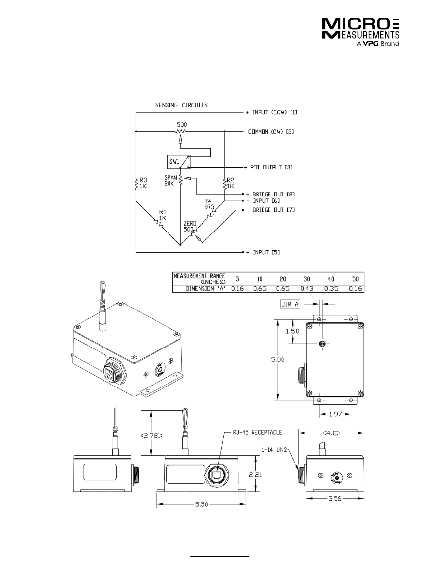
For technical questions, contact
mm@vpgsensors.com
www.micro-measurements.com
146
Document No.: 11004
Revision: 15-Nov-2015
Cable-Extension Displacement Sensor
Special Use Sensors—Cable-Extension Displacement Sensors
OUTLINE DIMENSIONS
in inches

For technical questions, contact
mm@vpgsensors.com
www.micro-measurements.com
147
Strain Gage
Accessories and
Instruments
Strain Gage Installation ....................... 148
Instrument Selection .......................... 151
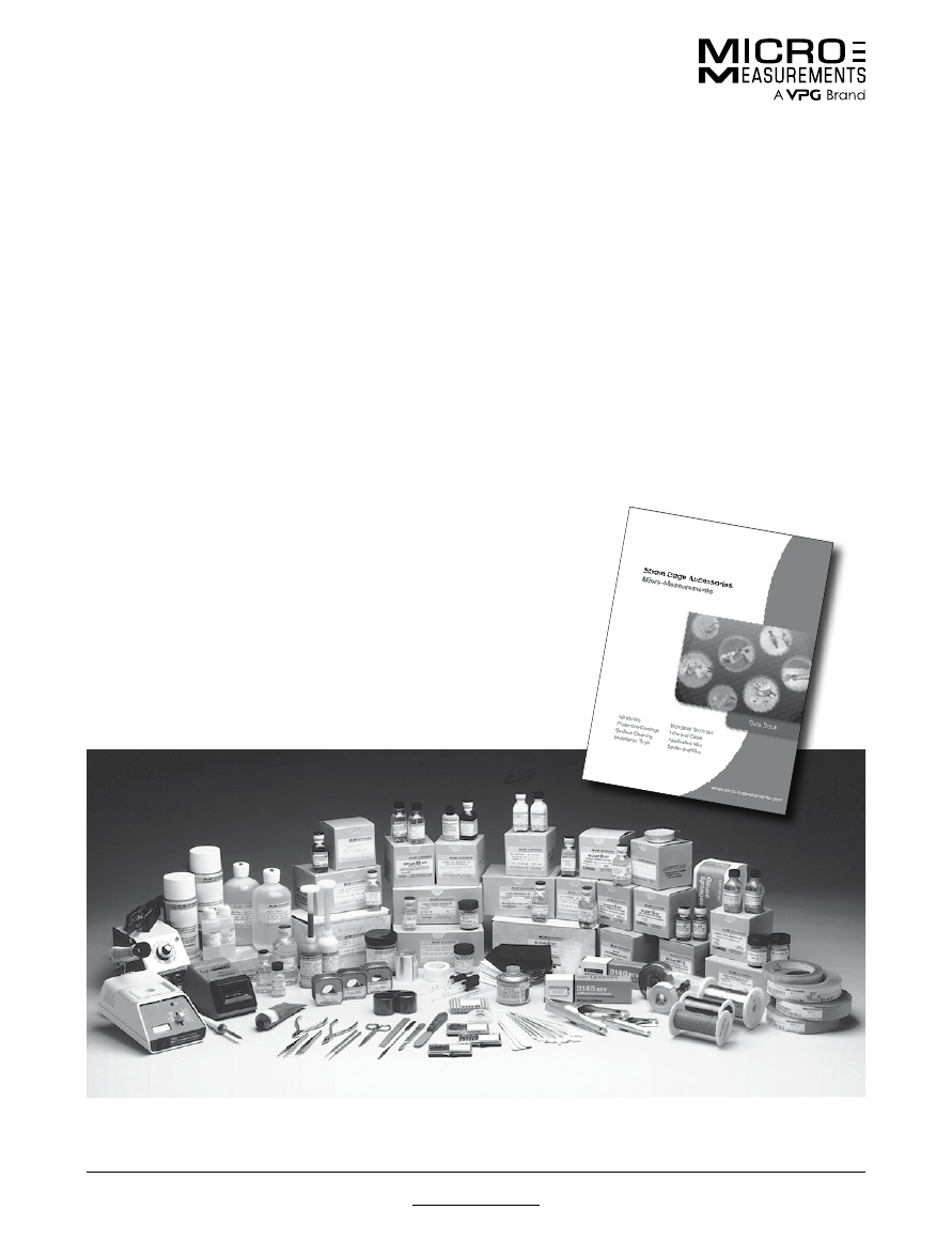
For technical questions, contact
mm@vpgsensors.com
www.micro-measurements.com
148
Document No.: 11006
Revision: 15-Nov-2015
Strain Gage Installation
Micro-Measurements Strain Gage Accessories
Micro-Measurements Strain Gage Accessories
Micro-Measurements strain gages are produced under
rigidly controlled manufacturing conditions, with the
utmost care and attention given to ensuring the high level
of quality for which these gages have gained world-
wide recognition. However, the gages’ full potential
for accurate strain measurement can be realized only
when they are properly installed. There are, in fact, three
principal components in every strain gage installation:
(1) The strain gage itself, (2) the tools, materials, and
supplies (accessories) needed to install the gage,
and (3) the techniques employed in performing the
installation. Professional stress analysts have learned
from experience that compromising any of these may lead
to compromising the quality of the installation and the
accuracy of the strain data.
The well-established formula for making consistently
successful strain gage installations is quite simple:
• Select high-quality precision strain gages.
• Select professional-caliber accessories which
have been laboratory-tested and field-proven for
effectiveness and compatibility with the strain gages.
• Follow the installation procedures recommended by the
manufacturer of the gages and accessories.
A small sample of the Micro-Measurements strain gage
installation accessories is featured on the following two
pages. As indicated, the appropriate materials, supplies,
and tools are available for each important step in the
gage installation process—from preparing the surface of
the test piece to applying a protective coating over the
bonded and wired gage. All accessory items, whether
manufactured directly by Micro-Measurements or
specified for purchase from an outside supplier, are of
the highest quality, and have been designed or selected
specifically to help ensure successful installation of Micro-
Measurements strain gages.
Regular users of strain gages will want to request a
copy of Micro-Measurements Strain Gage Accessories
databook. This fully illustrated catalog describes the
complete line of gage installation accessories and related
equipment. In addition to detailed product descriptions
and specifications, it includes, where applicable,
extensive recommendations for the appropriate selection
and application of the accessories. Micro-Measurements
Strain Gage Accessories databook is available on
request from our Applications Engineering Department. A
complete listing is available on our website.
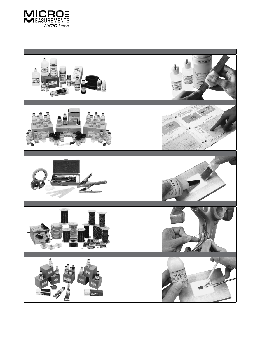
For technical questions, contact
mm@vpgsensors.com
Document No.: 11006
Revision: 15-Nov-2015
www.micro-measurements.com
149
Strain Gage Installation
Micro-Measurements Strain Gage Accessories
SIX SIMPLE STEPS TO SUCCESSFUL STRAIN GAGE INSTALLATION
1. Surface Preparation
CSM Degreaser
M-Prep Conditioner A
M-Prep Neutralizer 5A
Silicon-Carbide Paper
Cotton Tip Applicators
Gauze Sponges
2. Adhesive Selection
M-Bond 200
M-Bond AE-10
M-Bond AE-15
M-Bond 600
M-Bond 610
3. Gage Handling and Bonding
Gage Handling Tape
Mylar
®
Tape
Spring Clamps
Teflon
®
Film
Silicone Rubber Gum
Pads
Application Tools
4. Leadwire Attachment
Solder Terminals
Wires, Cables –
Solid, Stranded, Tinned
Solders
Soldering Station
Wiring Tools
5. Protective Coating Application
M-Coat A Polyurethane
M-Coat B Nitrile Rubber
M-Coat C
Silicone Rubber
M-Coat D Acrylic
M-Coat W-1
Microcrystalline Wax
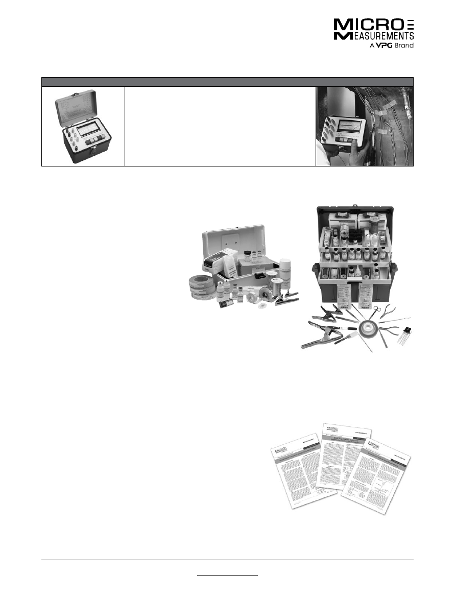
For technical questions, contact
mm@vpgsensors.com
www.micro-measurements.com
150
Document No.: 11006
Revision: 15-Nov-2015
Strain Gage Installation
Micro-Measurements Strain Gage Accessories
6. Gage Installation Tester
Reads insulation resistance (leakage) to 20 000 MΩ with 15 VDC.
Measures deviation of installed gage resistance from precise
standards to a resolution of 0.02%.
Auxiliary ohmmeter scale for troubleshooting questionable
installations.
Reads with the push of a button.
Verifies the complete gage circuit including leadwires.
INSTRUCTIONAL MATERIALS
Because technique is such an important ingredient in successful
strain gage installation, detailed
Instruction Bulletins
have
been prepared for virtually all Micro-Measurements strain gage
installation products.
In addition, a library of
Tech Notes
and
Application Notes
is
available for reference on a broad range of subjects within
Strain Gage Technology.
Application Notes
present practical strain gage application
techniques for “out-of-the-ordinary” situations, and represent, as
much as possible, a practical “how-to” approach to strain gage
installation.
Tech Notes
contain in-depth technical treatments of specific
subjects having direct or indirect bearing on the successful
application of stress/strain measurement technology.
GENERAL APPLICATION KITS
It is often of greatest convenience for the
strain gage user to purchase all of the
needed accessory supplies and materials
in a single package.
GAK-2 Series Kits
provide specific
selections of M-LINE accessories for
making basic strain gage installations with
the M-Bond 200, AE-10, or 610 Adhesives.
The ultimate in gage installation capability
is provided by the
MAK-1, Master
Strain Gage Application Kit
. The MAK-1
includes all of the supplies and special
tools necessary for making a wide range of
gage installations for both laboratory and
field applications.
GAK-2 Series Kit
MAK-1 Master Strain
Gage Application Kit
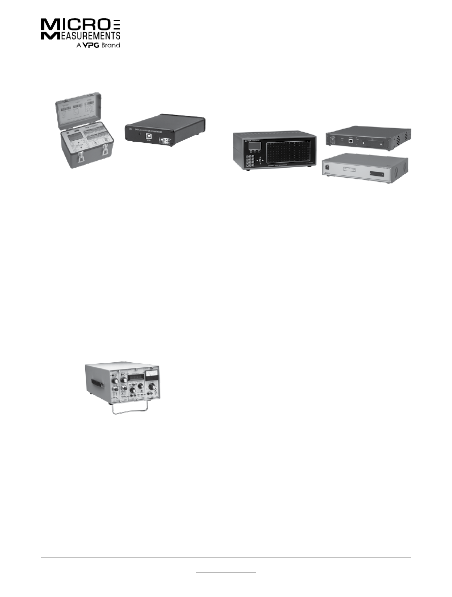
Instrument Selection
For technical questions, contact
mm@vpgsensors.com
Document No.: 11048
Revision: 05-Jan-2016
www.micro-measurements.com
151
Considerations for Instrument Selection
outputs suitable for multiple channel, simultaneous,
dynamic recording. All of these systems can be used in
conjunction with a variety of recording devices.
DIGITAL DATA SYSTEMS
Depending on their design, digital data systems can be
used for measurement of static, dynamic, or both kinds
of signals. Micro-Measurements offers three digital data
systems, each controlled with StrainSmart
®
software and
other third-party software.
System 7000 is a high performance dynamic data
acquisition instrument with measurement accuracy of
±0.05% of full scale. Each sensor card employs a 24-bit
analog to digital converter enabling 0.5 microstrain
resolution. Scan rates up to 2048 samples per second are
available for simultaneous reading of all sensor inputs.
A combination of analog and flexible Finite Impulse
Response (FIR) filters are available to provide adequate
anti-alias filtering at all scanning rates. Electronically
selectable bridge completion resistors allow the user to
choose between 120-, 350-, and 1000-ohm strain gages
through software selection. System 7000 is capable of
self-calibration with a removable calibration reference.
System 8000 is a versatile, precision data acquisition
instrument system intended for static and dynamic test
and measurement applications. The system includes a
scanner with 8 channels of data acquisition. A 10-foot
crossover Ethernet cable is also included. The scanners
may be used separately or up to 16 scanners can be
used concurrently for a maximum of 128 channels. Each
channel can be configured, via software, to accept signals
from strain gages or strain-gage-based transducers,
thermocouples, or high level voltage sensors. Strain
gage channels accept full-, half-, or quarter-bridge
configurations and have the required bridge completion
components for 120-, 350-, and 1000- ohm bridges.
Each scanner operates independently; multiple scanners
are not synchronized. The data is processed in a modern
24-bit digital signal processor and filtering is performed
using Finite Impulse Response (FIR), multi-stage filters.
This provides excellent noise rejection and stability and
unsurpassed measurement accuracy.
System 9000 from Micro-Measurements is a versatile,
precision data acquisition instrument system intended for
dynamic test and measurement applications. The system
includes a scanner with 12 channels of strain gage (strain
gauge) data acquisition and 4 configurable slots for high
level voltage sensors, thermocouples, and piezoelectric
transducers (charge mode and voltage mode). Strain
gage (strain gauge) channels accept full-, half-, or
STRAIN INDICATORS AND CALIBRATORS
Basic instrumentation requirements call for stability,
accuracy and high resolution when making measurements
under static loading conditions, and particularly where
measurements are to be taken over long periods of time.
Micro-Measurements offers our Model P3 Strain Indicator
and D4 Data Acquisition Conditioner to meet these
demanding criteria.
The Model P3 Strain Indicator and Recorder is a
portable, battery-operated instrument while our D4 is a
USB-powered instrument that connects to a personal
computer. Both are capable of simultaneously accepting
four inputs from quarter-, half-, and full-bridge strain-gage
circuits, including strain-gage-based transducers. A highly
stable measurement circuit, regulated bridge excitation
supply, and precisely settable gage factor enable
measurements of ±0.1% accuracy and 1 microstrain
resolution. The P3 can also be configured and operated
directly from your PC with a separate software application
included with each instrument. The D4 also has a
separate software application and is programmable for
custom applications.
SIGNAL CONDITIONING AMPLIFIERS
When signals are produced by dynamically applied
loads at frequencies above 0.1 Hz, or are transients,
measuring instrumentation requires adequate frequency
response, and a wide amplifier gain range for output
to the appropriate recording or display device. Such
an instrument consists of an amplifier and signal
conditioner with a built-in or shared power supply.
Individual units are normally required for each channel
when simultaneous recording or multiple channels are
needed. With the output sent to a suitable display device,
signal conditioning amplifiers can be used for making
long-term measurements under static loading conditions,
when maximum stability and accuracy are not primary
considerations.
The 2100, 2200, and 2300 Systems accept low-level
signals, and condition and amplify them into high-level
Instrument Selection
For technical questions, contact
mm@vpgsensors.com
www.micro-measurements.com
152
Document No.: 11048
Revision: 05-Jan-2016
Considerations for Instrument Selection
STRAIN INDICATORS AND CALIBRATORS
Instrument
Display
Operation
Bridge
Excitation
Input Power
Multi-Channel
Remarks
P3
Digital
Manual,
Direct-Reading
1.5 VDC
Battery, USB,
or AC Adapter
Selectable
Portable, 4-Channel,
0.1% Accuracy
D4
Host PC
PC Controlled
via USB
1.5 VDC
USB
Selectable
4-Channel,
0.1% Accuracy
SIGNAL CONDITIONING AMPLIFIERS
Instrument
Frequency
Response
(1)
Output (±)
Amplifier Gain
Bridge
Excitation
Input Power
Remarks
2100
DC 15 kHz
–3 dB
10 V at 100 mA
Continuously
Variable
1–2100
DC
0.5-12 V
AC
High Performance
Amplifier for
Simultaneous Dynamic
Recording
2200
DC 50 kHz
–0.5 dB
DC 100 kHz
–3 dB
10 V at 10 mA
and
1 VRMS at 10 mA
Continuously
Variable
1–3300
DC:
0.5-15 V or
0.5-30 mA
AC
High Performance,
for Demanding
Environments
2300
DC 60 kHz
–0.5 dB
DC 145 kHz
–3 dB
10 V
Continuously
Variable
1–11,000
DC:
0.7-15 V
(11 steps)
0.2-7 V Variable
AC
High-Frequency
Response
Multi-Feature
Signal Conditioner
(1)
Typical—see specific product bulletin and/or instruction manual for detailed performance specifications.
DIGITAL DATA SYSTEMS
Instrument
Operating
Mode
(2)
Channels
Scanning
Rate
Bridge
Excitation
(3)
Input
Power
Remarks
7000
Stationary,
Online
Unlimited
(in increments of 8)
10–2048
Samples/Sec/
Channel
0–10 VDC
Programmable
DC
(AC Optional)
Programmable
Digital Filters to
800 Hz
8000
Stationary,
Online
1-128
(in increments of 8)
10-1000
Samples/Sec
0–10 VDC
Programmable
DC
(AC Optional)
Anti-Alias
Low-Pass Filter
9000
Stationary,
Online
1-48
(in increments
of 16)
(4)
5-50,000
Samples/Sec/
Channel
0–10 VDC
Programmable
DC
(AC Optional)
Anti-Alias
Low-Pass Filter
(2)
All systems can be operated with StrainSmart software for data acquisition, storage, reduction, and presentation, or with other third-
party software.
(3)
Strain gage cards only.
(4)
System 9000, up to 12 of the 16 channels per unit can be strain gage inputs.
Considerations for instrument selection are provided on the previous page for all general-purpose instrumentation and
data systems produced by Micro-Measurements. Additionally, our Applications Engineering staff is always available to
assist you in selecting the right instrument for your specific applications.
INSTRUMENT SELECTION GUIDE
quarter-bridge configurations and have the required
bridge completion components for 120-, 350-, and
1000- ohm bridges. Three scanners can be connected
concurrently, providing 48 fully synchronized channels
of data acquisition (36 strain gage and 12 configurable).
The data is processed in a modern 24-bit digital signal
processor and filtering is performed using Finite Impulse
Response (FIR), multi-stage filters. This provides
excellent noise rejection and stability and unsurpassed
measurement accuracy. The Model 9000-16-SM Scanner
communicates with a host personal computer (PC) via
a DHCP auto configured Ethernet connection. Micro-
Measurements StrainSmart® software is optimal for
configuring, controlling, and acquiring data from the
System 9000.

For technical questions, contact
mm@vpgsensors.com
www.micro-measurements.com
153
Technical Data for
General-Use
Strain Gages
Gage Series—
Stress Analysis Gages ......................... 154
Optional Features—
Stress Analysis Gages ......................... 162
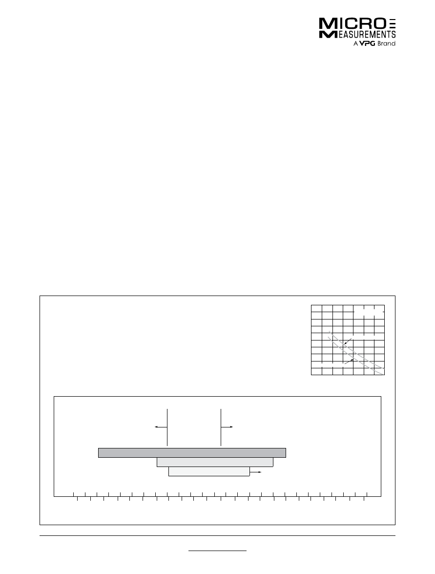
For technical questions, contact
mm@vpgsensors.com
www.micro-measurements.com
154
Document No.: 11506
Revision: 15-Nov-2015
Gage Series—Stress Analysis Gages
Technical Data
Technical Data
GAGE SERIES
All Micro-Measurements strain gages incorporate
precision foil grids mounted on organic backing materials.
The strain-sensing alloys and backing materials cannot
be arbitrarily combined in specifying a gage type. Instead,
a selection must be made from among the available
gage systems, or series, where each series generally
incorporates special design or construction features,
as well as a specific combination of alloy and backing
material.
Descriptions of all standard gage series are given on the
following pages, along with performance specifications
and application notes. The information includes, in each
case, the alloy and backing combination employed, as
well as the principal construction features common to
the series. The allowable strain range is specified, and
operating temperature ranges are recommended for
different types of applications.
The plots of cyclic strain level versus number of cycles
shown for each series represent general guidelines
for the nominal fatigue characteristics. This data is a
function of gage size with the upper curve indicative of
larger gage patterns, and the lower curve of smaller gage
patterns. Since the fatigue life of a strain gage is subject
to special interpretation, reference should be made
to Micro- Measurements Tech Note TN-508, “Fatigue
Characteristics of Micro-Measurements Strain Gages”, for
a full understanding of the plotted data.
The fatigue curves on the following pages correspond
to fully reversed strain levels. They can also be
applied, approximately, to unidirectional strains and to
combinations of mean and variable strains by derating
the peak-to-peak amplitude by 10%. As an example, a
fully reversed strain range of ±1500μ
ε
is approximately
equivalent in gage fatigue damage to strain levels of:
0 to +2700μ
ε
0 to –2700μ
ε
–200 to +2500μ
ε
However, a mean strain which increases in the tensile
direction during cycling will lead to much earlier failure.
It must be noted that all performance specifications
for strain gages are nominal, since the behavior of
a particular gage may be modified by installation or
application circumstances. Moreover, the specifications
apply primarily to gages of 0.125 in (3 mm) gage length
and larger, and without optional features, unless otherwise
indicated.
EA SERIES
EA-Series constantan gages are widely used in general-purpose experimental stress
analysis applications. The basic gage is of open-faced construction on a 0.001 in
(0.025 mm) tough, flexible cast polyimide backing. The strength and heat resistance
of this backing provide excellent handling and performance qualities. This series is
available in the widest range of patterns and will usually be the lowest in cost for a
particular pattern design. A large number of options may be obtained for EA-Series
gages, covering various forms of lead attachment and protective encapsulation. The
backing is treated for strong bond formation with all standard strain gage adhesives.
Strain limits are approximately ±5% for gages of 1/8 in (3 mm) or greater gage length
and ±3% for smaller sizes.
FATIGUE LIFE FOR
EA-SERIES GAGES
LARGE GAGES
SMALL GAGES
10
10
2
10
3
10
4
10
5
10
6
10
7
10
8
NUMBER OF CYCLES
±
3000
±
2600
±
2200
±
1800
±
1400
±
1000
CYCLIC STRAIN LEVEL
IN
µ∈
OPERATING TEMPERATURES FOR
EA
-SERIES GAGES
The thermal output of constantan
increases rapidly below –50°F
(–45°C). Static measurements be-
come difficult if temperatures are
varying.
Positive zero drift of constantan alloy increases
significantly above +150°F (+65°C) for single active
gages in static measurements. Use half-bridge or
full-bridge circuits when possible.
DYNAMIC OR SPECIAL EXTENDED RANGE
NORMAL STATIC RANGE
BEST STATIC RANGE
Creep Increases
TEMPERATURE IN °C
–250
–200
–150
–100
–50
0
+50
+100
+150
+200
+250
+300
+350
–400
–300
–200
–100
0
+100
+200
+300
+400
+500
+600
+700
TEMPERATURE IN °F
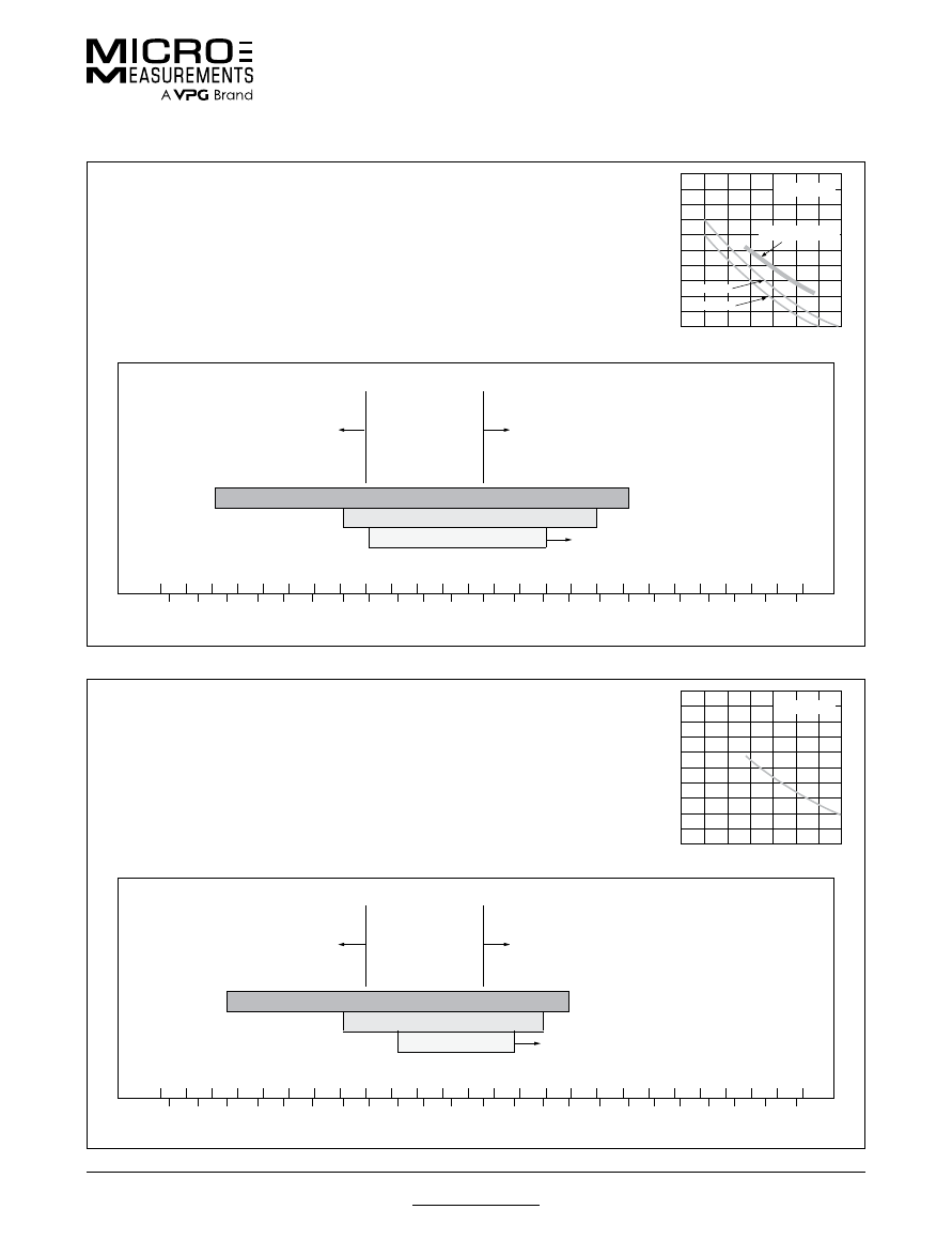
For technical questions, contact
mm@vpgsensors.com
Document No.: 11506
Revision: 15-Nov-2015
www.micro-measurements.com
155
Gage Series—Stress Analysis Gages
Technical Data
CEA SERIES
CEA-Series gages are the most widely accepted for use in general-purpose experimental
stress analysis applications in the world today. These polyimide encapsulated
constantan gages feature large, rugged, copper-coated tabs. This construction provides
optimum capability for attaching leadwires directly to the tabs, eliminating the need
for separate terminals. In most applications, the CEA Series is preferred over the EA
Series with options such as E, L, LE and W. Nominal single-plane gage thickness is
0.0027 in (0.069 mm); stacked rosettes, 0.0039 in (0.099 mm). The extremely tough but
flexible cast polyimide carrier can be contoured to almost any radius. Strain limits are
approximately ±5% (50 000 μ
ε
) for gage lengths 1/8 in (3 mm) or greater, and ±3% for
smaller sizes.
FATIGUE LIFE FOR
CEA-SERIES GAGES
LARGE GAGES
SMALL GAGES
10
10
2
10
3
10
4
10
5
10
6
10
7
10
8
NUMBER OF CYCLES
±
3000
±
2600
±
2200
±
1800
±
1400
±
1000
CYCLIC STRAIN LEVEL
IN
µ∈
LARGE GAGES USING
LOW MODULUS SOLDER
OPERATING TEMPERATURES FOR
CEA
-SERIES GAGES
The thermal output of constantan
increases rapidly below –50°F
(–45°C). Static measurements be-
come difficult if temperatures are
varying.
Positive zero drift of constantan alloy increases
significantly above +150°F (+65°C) for single active
gages in static measurements. Use half-bridge or
full-bridge circuits when possible. Stacked rosettes
are limited to a maximum operating temperature of
+150°F (+65°C).
DYNAMIC OR SPECIAL EXTENDED RANGE
NORMAL STATIC RANGE
BEST STATIC RANGE
Creep Increases
TEMPERATURE IN °C
–250
–200
–150
–100
–50
0
+50
+100
+150
+200
+250
+300
+350
–400
–300
–200
–100
0
+100
+200
+300
+400
+500
+600
+700
TEMPERATURE IN °F
N2A SERIES
N2A-Series gages are open-faced constantan on a special, thin, laminated polyimide
backing. The backing is very flexible and tough. Backing thickness is approximately
0.0008 in (0.020 mm), and the backing has been specially treated for optimum bond
formation. The N2A Series has an elongation capability of approximately ±3%. These
gages are intended for use in elastic strain fields. This series is primarily available for
certain large gage patterns because its flatness eases handling.
FATIGUE LIFE FOR
N2A-SERIES GAGES
10
10
2
10
3
10
4
10
5
10
6
10
7
10
8
NUMBER OF CYCLES
±
3000
±
2600
±
2200
±
1800
±
1400
±
1000
CYCLIC STRAIN LEVEL
IN
µ∈
OPERATING TEMPERATURES FOR
N2A
-SERIES GAGES
The thermal output of constantan
increases rapidly below –50°F
(–45°C). Static measurements be-
come difficult if temperatures are
varying.
Positive zero drift of constantan alloy increases
significantly above +150°F (+65°C) for single active
gages in static measurements. Use half-bridge or
full-bridge circuits when possible.
DYNAMIC OR SPECIAL EXTENDED RANGE
NORMAL STATIC RANGE
BEST STATIC RANGE
Creep Increases
TEMPERATURE IN °C
–250
–200
–150
–100
–50
0
+50
+100
+150
+200
+250
+300
+350
–400
–300
–200
–100
0
+100
+200
+300
+400
+500
+600
+700
TEMPERATURE IN °F
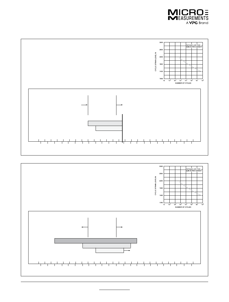
For technical questions, contact
mm@vpgsensors.com
www.micro-measurements.com
156
Document No.: 11506
Revision: 15-Nov-2015
Gage Series—Stress Analysis Gages
Technical Data
C2A SERIES
C2A series gages are designed to save time in gage installation. They are fully
encapsulated constantan alloy gages with pre-attached 3-conductor instrument cables.
Flexible and rugged polyimide film backing and encapsulation allows these gages to be
installed on almost any radius. Pre-attached 10-ft (3 m) 26-AWG stranded instrument
cable requires no soldering. Economical and easy to install, the C2A series is available
in linear, shear, Tee-Rosette and Rectangular Rosette patterns. Nominal gage thickness
0.002 in (0.05 mm). Jumper wire between gage and instrument cable is 34 AWG single-
conductor, polyurethane insulated copper wire 1 in (25 mm) long. Solder used for the
connections is +430°F (+220°C) melting point, lead-free type. Strain limits ±3%.
±
±
±
±
±
±
µ∈
OPERATING TEMPERATURES FOR
C2A
-SERIES GAGES
Wire insulation limit
Positive zero drift of constantan alloy increases
significantly above +150°F (+65°C) for single active
gages in static measurements. Use half-bridge or
full-bridge circuits when possible.
NORMAL STATIC RANGE
Wire Insulation Limit
BEST STATIC RANGE
TEMPERATURE IN °C
–250
–200
–150
–100
–50
0
+50
+100
+150
+200
+250
+300
+350
–400
–300
–200
–100
0
+100
+200
+300
+400
+500
+600
+700
TEMPERATURE IN °F
L2A SERIES
L2A series gages are fully encapsulated constantan alloy gages with pre-attached
nickel-clad copper lead ribbons. Flexible and rugged polyimide film backing and
encapsulation allows these gages to be installed on almost any radius. Available in linear,
shear, Tee-Rosette and Rectangular Rosette patterns, L2A gages are the lowest cost
pre-leaded gage series, and also save you time in gage installation by eliminating direct
soldering on the gage foil. Preattached leads are 1.2 in (30 mm) long, 0.016 in (0.4 mm)
wide and 0.002 inch (0.05 mm) thick nickel-clad copper ribbon soldered with +430°F
(+220°C) lead-free solder. Nominal gage thickness is 0.002 in (0.05 mm). Strain
limits ±3%.
±
±
±
±
±
±
µ∈
OPERATING TEMPERATURES FOR
L2A
-SERIES GAGES
The thermal output of constantan
increases rapidly below –50°F
(–45°C). Static measurements be-
come difficult if temperatures are
varying.
Positive zero drift of constantan alloy increases
significantly above +150°F (+65°C) for single active
gages in static measurements. Use half-bridge or
full-bridge circuits when possible.
DYNAMIC OR SPECIAL EXTENDED RANGE
NORMAL STATIC RANGE
BEST STATIC RANGE
Creep Increases
TEMPERATURE IN °C
–250
–200
–150
–100
–50
0
+50
+100
+150
+200
+250
+300
+350
–400
–300
–200
–100
0
+100
+200
+300
+400
+500
+600
+700
TEMPERATURE IN °F
For technical questions, contact
mm@vpgsensors.com
Document No.: 11506
Revision: 15-Nov-2015
www.micro-measurements.com
157
Gage Series—Stress Analysis Gages
Technical Data
WA SERIES
WA-Series gages are fully encapsulated constantan, equipped with integral, high-
endurance beryllium copper leadwires. The backing and encapsulation matrix consists
of a high-temperature epoxy-phenolic resin system reinforced with glass fibers. Overall
gage thickness is approximately 0.0028 in (0.071 mm). The WA construction provides
a gage that is strong and easy to handle, though not as flexible as the EA type. The
backing is treated for strong bond formation with all standard strain gage adhesives. The
strain range is limited to approximately ±1 to 2% by the hard, creep-resistant matrix.
WA-Series gages are primarily intended for high accuracy measurements over wider
temperature ranges and in more difficult environments than other forms of constantan
gages. Option W is available on some WA-Series gages, but will restrict the fatigue life
to some extent. Heat-curing adhesives such as M-Bond 600 or 610 are recommended
when full-temperature-range capabilities are required.
FATIGUE LIFE FOR
WA-SERIES GAGES
10
10
2
10
3
10
4
10
5
10
6
10
7
10
8
NUMBER OF CYCLES
±
3000
±
2600
±
2200
±
1800
±
1400
±
1000
CYCLIC STRAIN LEVEL
IN
µ∈
LARGE GAGES
SMALL GAGES
OPERATING TEMPERATURES FOR
WA
-SERIES GAGES
The thermal output of constantan
increases rapidly below –50°F
(–45°C). Static measurements be-
come difficult if temperatures are
varying.
Positive zero drift of constantan alloy increases
significantly above +150°F (+65°C) for single active
gages in static measurements. Use half-bridge or
full-bridge circuits when possible.
DYNAMIC OR SPECIAL EXTENDED RANGE
NORMAL STATIC RANGE
BEST STATIC RANGE
C
°
N
I
E
R
U
T
A
R
E
P
M
E
T
Solder Limit
–250
–200
–150
–100
–50
0
+50
+100
+150
+200
+250
+300
+350
–400
–300
–200
–100
0
+100
+200
+300
+400
+500
+600
+700
TEMPERATURE IN °F
SA SERIES
SA-Series gages are fully encapsulated constantan similar to WA-Series gages, but with
solder dots instead of leadwires. The matrix is somewhat thinner than the WA type, with
an overall gage thickness of approximately 0.002 in (0.05 mm). The solder is a lead-tin-
silver alloy which melts at approximately +570°F (+300°C). These gages are typically
used in stress analysis applications when mounting space is restricted. The solder dot
connections permit small jumper wires to be attached from any direction, and the matrix
can be field-trimmed very close to the pattern since no integral leadwires are involved.
Because of the exposed solder dots, SA-Series gages are not as well protected
in extreme environments as the WA type. The WA Series is superior in maximum
temperature capability and fatigue life. No leadwire options are available in this series.
Strain limits are approximately ±1 to 2%. Heat-curing adhesives such as M-Bond 600 or
610 are recommended for full-range performance.
FA TIGUE LIFE FO R
SA -SERIES GAGES
10
10
2
10
3
10
4
10
5
10
6
10
7
10
8
NUMBER OF CYCLES
±
3000
±
2600
±
2200
±
1800
±
1400
±
1000
CYCLIC STRAIN LEVEL
IN
µ
∈
LARGE GAGES
SMAL L GAGES
OPERATING TEMPERATURES FOR
SA
-SERIES GAGES
DYNAMIC OR SPECIAL EXTENDED RANGE
NORMAL STATIC RANGE
BEST STATIC RANGE
Solder Limit
TEMPERATURE IN °C
–250
–200
–150
–100
–50
0
+50
+100
+150
+200
+250
+300
+350
–400
–300
–200
–100
0
+100
+200
+300
+400
+500
+600
+700
TEMPERATURE IN °F
For technical questions, contact
mm@vpgsensors.com
www.micro-measurements.com
158
Document No.: 11506
Revision: 15-Nov-2015
Gage Series—Stress Analysis Gages
Technical Data
EP SERIES
EP-Series gages are specifically designed for use in the measurement of large strains,
>3–5%. The basic gage is of open-faced construction on a 0.001 in (0.025 mm) tough,
flexible, high-elongation cast polyimide backing. The sensing grid is a special grade
of fully annealed constantan foil for maximum ductility. This gage series is available in
08 and 40 compensations, for use on metals and plastic, respectively. Exact values of
self-temperature compensation are usually not important in post-yield work because
the thermal output error is very small compared to the large strain levels being
measured. Strain limits for EP-Series gages are approximately ±20% for gages of 1/8 in
(3 mm) or greater gage length, and ±10% for smaller sizes. Optional features generally
degrade elongation capabilities. EP-Series gages can be obtained on special order
with all options offered on the equivalent EA-Series pattern. M-Bond A-12 adhesive is
recommended for full elongation capability.
FATIGUE LIFE FOR
EP-SERIES GAGES
10
10
2
10
3
10
4
10
5
10
6
10
7
10
8
NUMBER OF CYCLES
±
3000
±
2600
±
2200
±
1800
±
1400
±
1000
CYCLIC STRAIN LEVEL
IN
µ∈
500
µ∈
ZERO-SHIFT
200
µ∈
ZERO-SHIFT
OPERATING TEMPERATURES FOR
EP
-SERIES GAGES
Elongation capability of gage and
adhesive is restricted at temper-
atures below –50°F (–45°C).
Currently adhesive-limited
EXTENDED OR SPECIAL RANGE
NORMAL RANGE
C
°
N
I
E
R
U
T
A
R
E
P
M
E
T
–250
–200
–150
–100
–50
0
+50
+100
+150
+200
+250
+300
+350
–400
–300
–200
–100
0
+100
+200
+300
+400
+500
+600
+700
TEMPERATURE IN °F
ED SERIES
ED-Series gages are used in general-purpose dynamic-only strain measurement.
They are openfaced construction on a thin, 0.001 in (0.025 mm), tough, flexible cast
polyimide backing. The isoelastic grid alloy has a high strain sensitivity, and gage
factor is approximately 3.2. The extremely high temperature coefficient of resistance
(thermal output of approximately 80μ
ε
/°F (145μ
ε
/°C)) does not normally permit static
measurements to be made with isoelastic gages. The outstanding features of the ED
Series are excellent handling properties, high flexibility, good fatigue life, and relatively
low cost. A wide range of options is available, covering various forms of lead attachment
and protective encapsulation. Leadwires must be handled and installed with care to
avoid reduction in fatigue life. All isoelastic gages tend to generate error signals in
magnetic fields, since the alloy is both magnetic and magnetostrictive. Strain limits for
ED gages are approximately ±1%, but increasing nonlinearity above ±5000μ
ε
normally
restricts this type of gage to measurement of dynamic, elastic strain levels.
FATIGUE LIFE FOR
ED-SERIES GAGES
10
10
2
10
3
10
4
10
5
10
6
10
7
10
8
NUMBER OF CYCLES
±
6000
±
5000
±
4000
±
3000
±
2000
±
1000
CYCLIC STRAIN LEVEL
IN
µ∈
LARGE GAGES
SMALL GAGES
OPERATING TEMPERATURES FOR
ED
-SERIES GAGES
FULL DYNAMIC RANGE
BEST DYNAMIC RANGE
C
°
N
I
E
R
U
T
A
R
E
P
M
E
T
–250
–200
–150
–100
–50
0
+50
+100
+150
+200
+250
+300
+350
–400
–300
–200
–100
0
+100
+200
+300
+400
+500
+600
+700
TEMPERATURE IN °F
For technical questions, contact
mm@vpgsensors.com
Document No.: 11506
Revision: 15-Nov-2015
www.micro-measurements.com
159
Gage Series—Stress Analysis Gages
Technical Data
WD SERIES
WD-Series gages are fully encapsulated isoelastic alloy with integral, high-endurance
beryllium copper leadwires. The matrix is a high-temperature epoxy-phenolic resin
system reinforced with glass fibers. Overall gage thickness is approximately 0.0028
in (0.071 mm). These gages are excellent in dynamic strain measurement over wide
temperature ranges. The WD Series is considerably less flexible than the ED type,
but is useful over a wider temperature range and in more severe environments. The
encapsulation matrix and integral high-endurance leadwires provide higher fatigue life
than ED-Series gages. No standard options are available. Strain limits for WD-Series
gages are approximately ±5000μ
ε
. Heat-curing adhesives such as M-Bond 600 or 610
will provide best overall performance.
FATIGUE LIFE FOR
WD-SERIES GAGES
10
10
2
10
3
10
4
10
5
10
6
10
7
10
8
NUMBER OF CYCLES
±
6000
±
5000
±
4000
±
3000
±
2000
±
1000
CYCLIC STRAIN LEVEL
IN
µ∈
LARGE GAGES
SMALL GAGES
OPERATING TEMPERATURES FOR
WD
-SERIES GAGES
Isoelastic gages become increasingly
nonlinear at high strain levels as tem-
peratures increase, due to decrease in
the elastic limit of the alloy.
SPECIAL OR EXTENDED DYNAMIC RANGE
FULL DYNAMIC RANGE
Backing life is reduced as
temperature increases
BEST DYNAMIC RANGE
TEMPERATURE IN °C
Solder Melts at +770°F (+410°C)
–250
–200
–150
–100
–50
0
+50
+100
+150
+200
+250
+300
+350
–400
–300
–200
–100
0
+100
+200
+300
+400
+500
+600
+700
TEMPERATURE IN °F
SD SERIES
SD-Series gages are fully encapsulated isoelastic alloy similar to WD-Series gages, but
with solder dots instead of leadwires. The matrix is somewhat thinner than the WD type,
with an overall thickness of approximately 0.002 in (0.05 mm). The solder is a lead-tin-
silver alloy which melts at +570°F (+300°C). The SD Series is primarily used over the
WD type when the matrix must be trimmed very close to the gage pattern because of
restricted mounting space. There are no integral leadwires to restrict trimming of the
lower edge of the matrix, and attachment wires can be routed to the solder dot tabs
from any direction. Both maximum operating temperature and fatigue life are somewhat
lower than in the WD Series because of the exposed solder dots. Strain limits are
approximately ±1%, but nonlinearity becomes increasingly severe above ±5000μ
ε
. Heat-
curing adhesives such as M-Bond 600 or 610 will provide best overall performance.
FATIGUE LIFE FOR
SD-SERIES GAGES
10
10
2
10
3
10
4
10
5
10
6
10
7
10
8
NUMBER OF CYCLES
±
6000
±
5000
±
4000
±
3000
±
2000
±
1000
CYCLIC STRAIN LEVEL
IN
µ∈
LARGE GAGES
SMALL GAGES
OPERATING TEMPERATURES FOR
SD
-SERIES GAGES
Isoelastic gages become increas-
ingly nonlinear at high strain levels
as temperatures increase, due to
decrease in the elastic limit of the
alloy.
SPECIAL OR EXTENDED DYNAMIC RANGE
FULL DYNAMIC RANGE
BEST DYNAMIC RANGE
Solder Limit
C
°
N
I
E
R
U
T
A
R
E
P
M
E
T
–250
–200
–150
–100
–50
0
+50
+100
+150
+200
+250
+300
+350
–400
–300
–200
–100
0
+100
+200
+300
+400
+500
+600
+700
TEMPERATURE IN °F
For technical questions, contact
mm@vpgsensors.com
www.micro-measurements.com
160
Document No.: 11506
Revision: 15-Nov-2015
Gage Series—Stress Analysis Gages
Technical Data
EK SERIES
EK-Series gages are K alloy, often employed in general-purpose testing where higher
resistances and grid stability are required, particularly at elevated temperatures. They
are normally selected for applications where reinforced laminate-backed gages lack
sufficient flexibility. EK gages are of openfaced construction on a 0.001 in (0.025 mm)
tough, flexible cast polyimide backing. The strong, heat-resistant backing provides
excellent handling and performance qualities, and is treated for good bond formation
with all standard strain gage adhesives. Heat-curing adhesives such as M-Bond 610
are recommended for full-temperature-range capabilities. Strain limits for this series are
approximately ±1.5%. EK gages are often selected instead of EA gages for improved
fatigue life. However, when maximum fatigue life is required, reinforced laminate-backed
K-alloy gages are recommended. Soldering to K-alloy is difficult, and duplex copper
pads or dots are included as a standard feature. Most options available on EA-Series
gages are offered with EK gages, but performance may be degraded.
FATIGUE LIFE FOR
EK-SERIES GAGES
10
10
2
10
3
10
4
10
5
10
6
10
7
10
8
NUMBER OF CYCLES
±
6000
±
5000
±
4000
±
3000
±
2000
±
1000
CYCLIC STRAIN LEVEL
IN
µ∈
LARGE GAGES
SMALL GAGES
OPERATING TEMPERATURES FOR
EK
-SERIES GAGES
DYNAMIC OR EXTENDED STATIC RANGE
NORMAL STATIC RANGE
BEST STATIC RANGE
Creep Increases
TEMPERATURE IN °C
–250
–200
–150
–100
–50
0
+50
+100
+150
+200
+250
+300
+350
–400
–300
–200
–100
0
+100
+200
+300
+400
+500
+600
+700
TEMPERATURE IN °F
WK SERIES
WK-Series gages are fully encapsulated K alloy, equipped with integral, high-endurance
beryllium copper leadwires. The matrix is a high-temperature epoxy-phenolic resin
system reinforced with glass fibers. Overall gage thickness is approximately 0.0028 in
(0.071 mm). WK-Series gages have the widest temperature range and most extensive
environmental capability of any general purpose strain gage of the self-temperature-
compensated type. Option W is available on many pattern designs, but will lower the
excellent cyclic endurance and maximum operating temperature of the basic WK gage.
Elevated temperature drift of these gages is very low to +600°F (+315°C), and the main
restriction at high temperatures is the limited life of the backing and adhesive due to
oxidation and sublimation. Strain limits for WK gages are approximately ±1.5%. High
temperature adhesives such as M-Bond 610 are required for full-range performance.
FATIGUE LIFE FOR
WK-SERIES GAGES
10
10
2
10
3
10
4
10
5
10
6
10
7
10
8
NUMBER OF CYCLES
±
6000
±
5000
±
4000
±
3000
±
2000
±
1000
CYCLIC STRAIN LEVEL
IN
µ∈
LARGE GAGES
SMALL GAGES
OPERATING TEMPERATURES FOR
WK
-SERIES GAGES
Typical backing and adhesive life in hours at temperatures
indicated below
INERT GAS
5 x 10
5
5 x 10
4
300
10
AIR
10
5
10
4
150
5
SPECIAL OR EXTENDED RANGE
NORMAL STATIC RANGE
BEST STATIC RANGE
TEMPERATURE IN °C
Solder Melts at +770°F (+410°C)
–250
–200
–150
–100
–50
0
+50
+100
+150
+200
+250
+300
+350
–400
–300
–200
–100
0
+100
+200
+300
+400
+500
+600
+700
TEMPERATURE IN °F
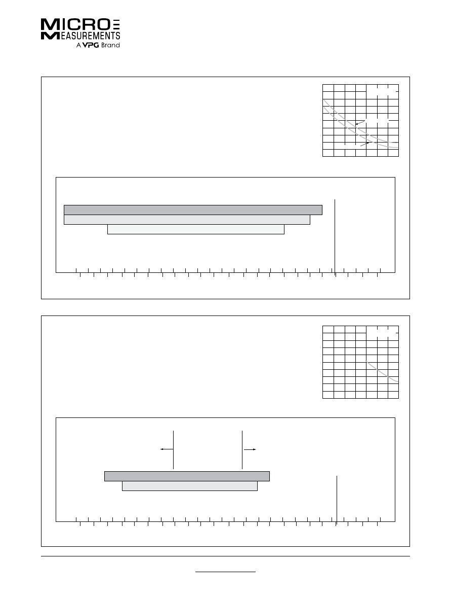
For technical questions, contact
mm@vpgsensors.com
Document No.: 11506
Revision: 15-Nov-2015
www.micro-measurements.com
161
Gage Series—Stress Analysis Gages
Technical Data
SK SERIES
SK-Series gages are fully encapsulated similar to the WK-Series gages, but with solder
dots instead of leadwires. The matrix is somewhat thinner than the WK type, with an
overall thickness of approximately 0.002 in (0.05 mm). The solder is a lead-tin-silver
alloy which melts at approximately +570°F (+300°C). SK gages are primarily used when
mounting space is restricted. Performance is equivalent to the WK type, but over a lower
temperature range. Fatigue life of the SK Series is equivalent to the WK type, but more
care is required during leadwire attachment to avoid gage damage. The absence of
integral leadwires allows SK gages to be field-trimmed very close to the pattern size. No
leadwire options are available. Strain limits are approximately ±1.5%. Heat-curing
adhesives such as M-Bond 610 will provide best overall performance.
FATIGUE LIFE FOR
SK-SERIES GAGES
10
10
2
10
3
10
4
10
5
10
6
10
7
10
8
NUMBER OF CYCLES
±
6000
±
5000
±
4000
±
3000
±
2000
±
1000
CYCLIC STRAIN LEVEL
IN
µ∈
LARGE GAGES
SMALL GAGES
OPERATING TEMPERATURES FOR
SK
-SERIES GAGES
SPECIAL OR EXTENDED RANGE
NORMAL STATIC RANGE
BEST STATIC RANGE
Solder Limit
C
°
N
I
E
R
U
T
A
R
E
P
M
E
T
–250
–200
–150
–100
–50
0
+50
+100
+150
+200
+250
+300
+350
–400
–300
–200
–100
0
+100
+200
+300
+400
+500
+600
+700
TEMPERATURE IN °F
S2K SERIES
S2K-Series gages are fully encapsulated K alloy, equipped with large integral solder
dots. The backing and encapsulation are 0.001 in (0.025 mm) thick laminated high-
performance polyimide. The overlay fully encapsulates the grid and solder tabs. Large
[0.030 in (0.75 mm)] diameter solder pads are provided for ease of leadwire attachment.
Overall gage thickness is approximately 0.0025 in (0.065 mm) and the backing has
been specially treated for optimum bond formation. M-Bond 43-B is recommended for
S2K-Series gages if a cure temperature of +350°F (+175°C) is possible. Alternatively,
M-Bond AE-10/15, M-Bond 200, or M-Bond 600/610 may be used. The S2K Series has
an elongation capability exceeding ±1.5%. Designed primarily for use on composites,
these gages are normally produced in larger patterns and higher resistances.
FATIGUE LIFE FOR
S2K-SERIES GAGES
10
10
2
10
3
10
4
10
5
10
6
10
7
10
8
NUMBER OF CYCLES
±
3000
±
2600
±
2200
±
1800
±
1400
±
1000
CYCLIC STRAIN LEVEL
IN
µ∈
OPERATING TEMPERATURES FOR
S2K
-SERIES GAGES
Gage factor drops more rapidly
below –300°F (–185°C).
Maximum operating temperatures are usually
restricted by creep effects.
DYNAMIC OR SPECIAL STATIC EXTENDED RANGE
NORMAL STATIC RANGE
Solder Limit
TEMPERATURE IN °C
–250
–200
–150
–100
–50
0
+50
+100
+150
+200
+250
+300 +350
–400
–300
–200
–100
0
+100
+200
+300
+400
+500
+600
+700
TEMPERATURE IN °F
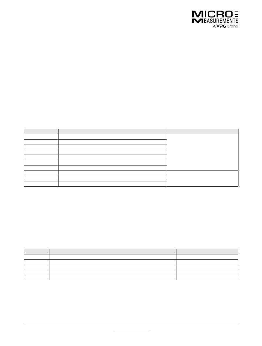
For technical questions, contact
mm@vpgsensors.com
www.micro-measurements.com
162
Document No.: 11506
Revision: 15-Nov-2015
Optional Features—Stress Analysis Gages
Technical Data
Technical Data
OPTIONAL FEATURES
Micro-Measurements offers a wide selection of optional
features for its general-purpose strain gages and special-
purpose sensors. The addition of options to the basic
gage construction usually increases the cost, but this is
generally offset by the benefits. Examples are:
• Significant reduction of installation time and costs.
• Reduction of the skill level necessary to make
dependable installations.
• Increased reliability of applications.
• Simplified installation of sensors in difficult locations on
components or in the field.
• Increased protection, both in handling during installation
and shielding from the test environment.
• Achievement of special performance characteristics.
Availability of each option varies with gage series and
pattern. Standard options are noted for each sensor in the
product listing.
Shown below is a summary of the optional features
offered. Detailed descriptions will be found on the
following pages.
STANDARD OPTIONS
The optional features shown below are considered standard when they are listed with the gage series and pattern in the
General-Purpose Strain Gage Listings.
OPTION
BRIEF DESCRIPTON
AVAILABLE ON GAGE SERIES
W
Integral Terminals and Encapsulation
As shown in
General-Use Strain
Gage Listings
E
Encapsulation with Exposed Tabs
SE
Solder Dots and Encapsulation
L
Preattached Leads
LE
Preattached Leads and Encapsulation
P
Preattached Leadwire Cables and Encapsulation
P2
Preattached Leadwire Cables for CEA-Series Gages
R
Individually Furnished Resistance Value
Special order required
S
Solder Dots
W3
Special Terminals
If the option desired is not shown in the Strain Gage Listings, it may be available as a special order. Please contact our Applications
Engineering Department for specific information.
SPECIAL OPTIONS
The following applies to Special Options:
1. Availability will depend on the specific gage series and
pattern.
2. A quotation is required and can be requested from our
Customer Service Department.
3. A minimum order quantity may be required.
4. Whenever more than one Special Option is required, a
custom part number will be assigned to the gage/option
combination.
OPTION
BRIEF DESCRIPTON
AVAILABLE ON GAGE SERIES
SP-11-14
Single Batch of Foil per Order
All
SP21-24
‘Modulus-Compensating’ Foil
EK, WK, SK, S2K
SP30
Round Ni-Clad Copper Leads
EA, WA, ED, WD, EK, WK, EP
SP60
Special Encapsulation
Only on Manganin Gages
SP61
Preattached Leads and Encapsulation
N2A, N2P
Note 1:
Products with designations and options shown in
bold
are not RoHS compliant.
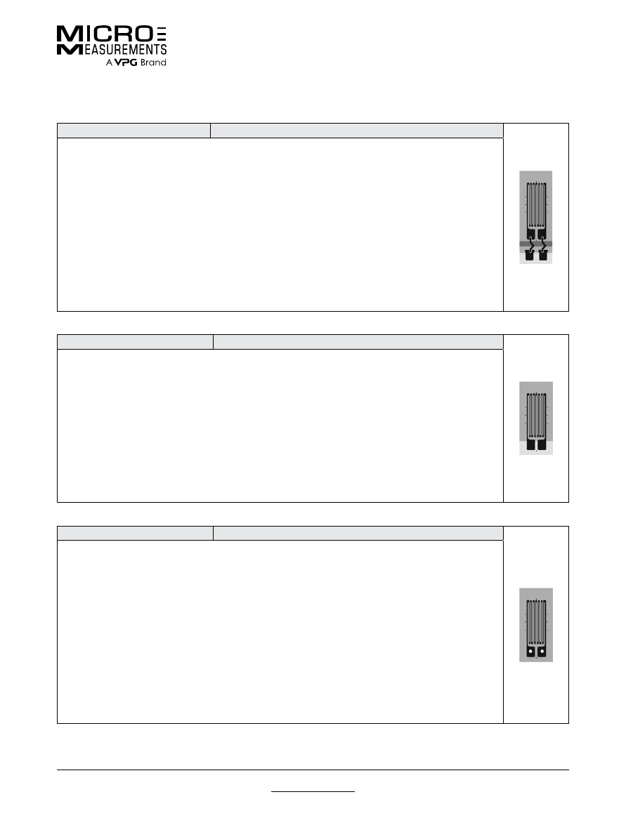
For technical questions, contact
mm@vpgsensors.com
Document No.: 11506
Revision: 15-Nov-2015
www.micro-measurements.com
163
Optional Features—Stress Analysis Gages
Technical Data
STANDARD OPTIONS
OPTION W
SERIES AVAILABILITY: EA, EP, WA, ED, WD, EK, WK
General Description:
This option provides encapsulation, and thin, printed circuit terminals at the tab end of the
gage. Beryllium copper jumpers connect the terminals to the gage tabs. The terminals are 0.0014 in (0.036 mm)
thick copper on polyimide backing nominally 0.0015 in (0.038 mm) thick. Option W gages are rugged and well
protected, and permit the direct attachment of larger leadwires than would be possible with open-faced gages.
This option is primarily used on EA-Series gages for general-purpose applications.
Solder:
+430°F (+220°C)
tin-silver alloy solder joints on E-backed gages, +570°F (+300°C) lead-tin-silver alloy solder joints on W-backed
gages.
Temperature Limit:
+350°F (+175°C) for E-backed gages, +450°F (+230°C) for W-backed gages.
Grid
Protection:
Entire grid and part of terminals are encapsulated with polyimide.
Fatigue Life:
Some loss in fatigue
life unless strain levels at the terminal location are below ±1000μ
ε
.
Size:
Option W extends from the soldering tab
end of the gages and thereby increases gage size. With some patterns, width is slightly greater.
Strain Range:
With some gage series, notably E-backed gages, strain range will be reduced. This effect is greatest with EP
gages, and Option W should be avoided with them if possible.
Flexibility:
Option W adds encapsulation, making
gages slightly thicker and stiffer. Conformance to curved surfaces will be somewhat reduced. In the terminal
area itself, stiffness is markedly increased.
Resistance Tolerance:
On E-backed gages, resistance tolerance is
normally doubled.
OPTION E
SERIES AVAILABILITY: EA, ED, EK, EP
General Description:
Option E consists of a protective encapsulation of polyimide film approximately 0.001 in
(0.025 mm) thick. This provides ruggedness and excellent grid protection, with little sacrifice in flexibility.
Soldering is greatly simplified since the solder is prevented from tinning any more of the gage tab than is
deliberately exposed for lead attachment. Option E protects the grid from fingerprints and other contaminating
agents during installation and, therefore, contributes significantly to long-term gage stability. Heavier leads may
be attached directly to the gage tabs for simple static load tests. Supplementary protective coatings should still
be applied after lead attachment in most cases.
Temperature Limit:
No degradation.
Grid Protection:
Entire grid
and part of tabs are encapsulated.
Fatigue Life:
When gages are properly wired with small jumpers, maximum
endurance is easily obtained.
Size:
Gage size is not affected.
Strain Range:
Strain range of gages will be
reduced because the additional reinforcement of the polyimide encapsulation can cause bond failure before the
gage reaches its full strain capability.
Flexibility:
Option E gages are almost as conformable on curved surfaces
as open-faced gages, since no internal leads or solder are present at the time of installation.
Resistance
Tolerance:
Resistance tolerance is normally doubled when Option E is selected.
OPTION SE
SERIES AVAILABILITY: EA, ED, EK, EP
General Description:
Option SE is the combination of solder dots on the gage tabs with a 0.001 in (0.025 mm)
polyimide encapsulation layer that covers the entire gage. The encapsulation is removed over the solder dots
providing access for lead attachment. These gages are very flexible, and well protected from handling damage
during installation. Option SE is primarily intended for small gages that must be installed in restricted areas,
since leadwires can be routed to the exposed solder dots from any direction. The option does not increase
overall gage dimensions, so the matrix may be field-trimmed very close to the actual pattern size. Option SE
is sometimes useful on miniature transducers of medium- or low-accuracy class, or in stress analysis work on
miniature parts.
Solder:
+570°F (+300°C) lead-tin-silver alloy. To prevent loss of long-term stability, gages with
Option SE must be soldered with noncorrosive (rosin) flux, and all flux residue should be carefully removed with
M-LINE
Rosin Solvent after wiring. Protective coatings should then be used.
Temperature Limit:
No degradation.
Grid Protection:
Entire gage is encapsulated.
Fatigue Life:
When gages are properly wired with small jumpers,
maximum endurance is easily obtained.
Size:
Gage size is not affected.
Strain Range:
Strain range of gages will
be reduced because the additional reinforcement of the polyimide encapsulation can cause bond failure before
the gage reaches its full strain capability.
Flexibility:
Option SE gages are almost as conformable on curved
surfaces as open-faced gages.
Resistance Tolerance:
Resistance tolerance is normally doubled when Option
SE is selected.
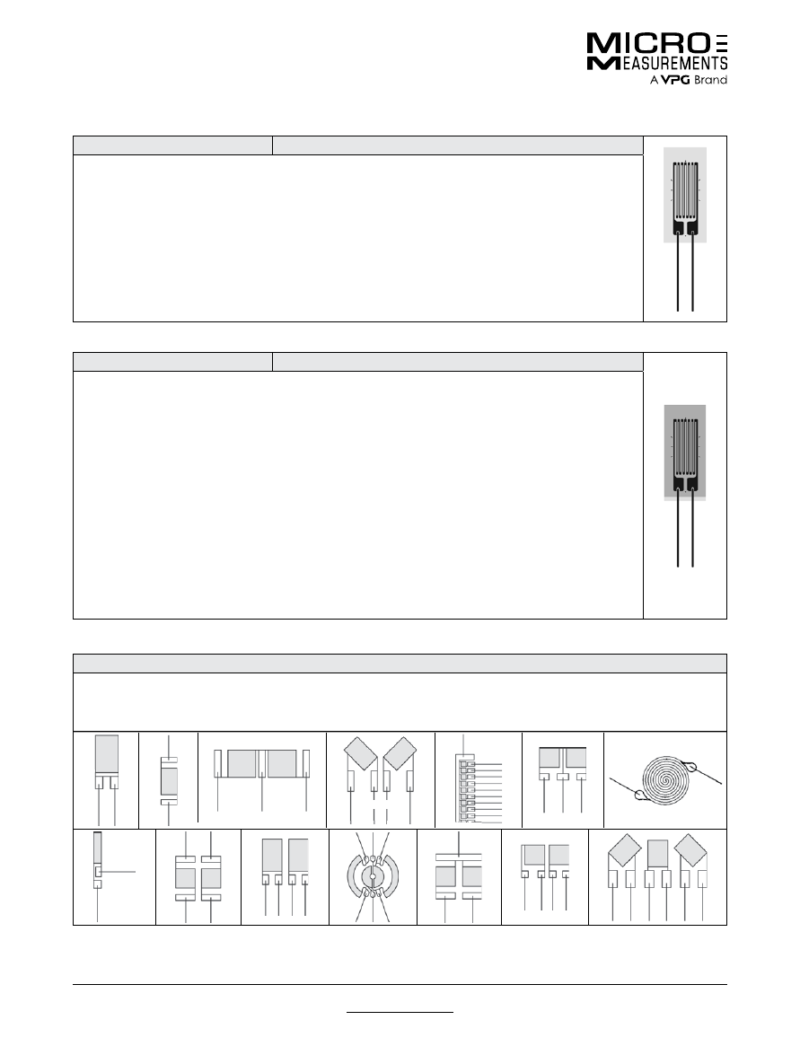
For technical questions, contact
mm@vpgsensors.com
www.micro-measurements.com
164
Document No.: 11506
Revision: 15-Nov-2015
Optional Features—Stress Analysis Gages
Technical Data
OPTION L
SERIES AVAILABILITY: EA, ED, EK, EP
General Description:
Option L is the addition of soft copper lead ribbons to open-faced polyimide-backed
gages. The use of this type of ribbon results in a thinner and more conformable gage than would be the case
with round wires of equivalent cross section. At the same time, the ribbon is so designed that it forms almost as
readily in any desired direction.
Leads:
Nominal ribbon size for most gages is 0.012 wide x 0.004 in thick (0.30
x 0.10 mm). Leads are approximately 0.8 in (20 mm) long.
Solder:
+430°F (+220°C) tin-silver alloy.
Temperature
Limit:
+400°F (+200°C).
Fatigue Life:
Fatigue life will normally be degraded by Option L. This occurs primarily
because the copper ribbon has limited cyclic endurance. When it is possible to carefully dress the leads so
that they are not bonded in a high strain field, the performance limitation will not apply. Option L is not often
recommended for very high endurance gages such as the ED Series.
Size:
Matrix size is unchanged.
Strain
Range:
Strain range will usually be reduced by the addition of Option L.
Flexibility:
Gages with Option L are not
as conformable as standard gages.
Resistance Tolerance:
Not affected.
OPTION LE
SERIES AVAILABILITY: EA, ED, EK, EP
General Description:
This option provides the same conformable soft copper lead ribbons as used in Option
L, but with the addition of a 0.001 in (0.025 mm) thick encapsulation layer of polyimide film. The encapsulation
layer provides excellent protection for the gage during handling and installation. It also contributes greatly to
environmental protection, though supplementary coatings are still recommended for field use. Gages with Option
LE will normally show better long-term stability than open-faced gages which are “waterproofed” only after
installation. A good part of the reason for this is that the encapsulation layer prevents contamination of the grid
surface from fingerprints or other agents during handling and installation. The presence of such contaminants
will cause some loss in gage stability, even though the gage is subsequently coated with protective compounds.
Leads:
Nominal ribbon size for most gages is 0.012 wide x 0.004 in thick (0.30 x 0.10 mm) copper ribbons. Leads
are approximately 0.8 in (20 mm) long.
Solder:
+430°F (+220°C) tin-silver alloy.
Temperature Limit:
+400°F
(+200°C).
Grid Protection:
Entire gage is encapsulated. A short extension of the backing is left uncovered at
the leadwire end to prevent contact between the leadwires and the specimen surface.
Fatigue Life:
Fatigue
life will normally be degraded by Option LE. This occurs primarily because the copper ribbon has limited cyclic
endurance. Option LE is not often recommended for very high endurance gages such as the ED Series.
Size:
Matrix size is unchanged.
Strain Range:
Strain range will usually be reduced by the addition of Option LE.
Flexibility:
Gages with Option LE are not as conformable as standard gages.
Resistance Tolerance:
Resistance
tolerance is normally doubled by the addition of Option LE.
LEADWIRE ORIENTATION FOR OPTIONS L AND LE
These illustrations show the standard orientation of leadwires relative to the gage pattern geometry for Options L and LE. The
general rule is that the leads are parallel to the longest dimension of the pattern. The illustrations also apply to leadwire orientation
for WA-, WK- and WD-Series gages, when the pattern shown is available in one of these series.
(3 or 4 tabs)

For technical questions, contact
mm@vpgsensors.com
Document No.: 11506
Revision: 15-Nov-2015
www.micro-measurements.com
165
Optional Features—Stress Analysis Gages
Technical Data
OPTION P
SERIES AVAILABILITY: EA, N2A
General Description:
Option P is the addition of preattached leadwire cables to many patterns of EA Series
strain gages. Encapsulation seals small “jumper” leadwires at gage end, and cable insulation protects solder
joints at cable end. Option P virtually eliminates need for soldering during gage installation.
Leads:
A pair of 1
in (25 mm)
M-LINE
134-AWP (solid copper, polyurethane enamel) single conductor “jumper” leadwires.
Cable:
10 ft (3.1 m) of color-coded, flat, three-conductor 26-gauge (0.404 mm dia.), stranded, tinned copper with vinyl
insulation (similar to M-LINE 326-DFV). Solder: +430°F (+220°C) tin-silver alloy solder joints, “jumper” to gage.
Cable conductors and “jumpers” joined with +361°F solder beneath cable insulation. Exposed leadwires on
unattached end of cable are pretinned for ease of hookup.
Temperature Limit:
–60° to +180°F (–50° to +80°C);
limited by vinyl insulation on cable.
Grid Encapsulation:
Entire grid and tabs are encapsulated.
Fatigue Life:
Fatigue life will normally be degraded by Option P, primarily because the copper “jumper” wires have limited
cyclic endurance.
Pattern Availability:
Most EA-Series single-grid patterns that are 0.062 in (1.5 mm) or
greater gage length, with parallel solder tabs on one end of the grid, and suitable for encapsulation. (Consult
our Applications Engineering Department for availability of Option P on other gage series/patterns, and for
nonstandard cable lengths.)
Size:
Matrix size is unchanged.
Strain Range:
Strain range will usually be reduced
by the addition of Option P.
Flexibility:
E-backed gages with Option P are not as conformable as standard
gages.
Resistance Considerations:
Each conductor of the cable has a nominal resistance of 0.04 ohm/ft (0.13
ohm/m). Gage resistance is measured at gage tabs.
Gage Factor:
Gage factor is determined for gages without
preattached cable.
Resistance Tolerance:
Resistance tolerance is normally ±0.5% for single-element gages,
and ±0.6% for multiple-grid gages.
OPTION P2
SERIES AVAILABILITY: CEA
General Description:
Option P2 is the addition of preattached leadwire cables to CEA-Series strain gages.
Option P2 virtually eliminates need for soldering during gage installation.
Cable:
10 ft (3.1 m) of color-coded, flat,
three-conductor 30-gauge (0.255 mm), stranded, tinned copper with vinyl insulation (similar to
M-LINE
330-DFV).
Solder: +361°F (+180°C) tin-lead alloy solder joints. Exposed leadwires on unattached end of cable are pretinned
for ease of hookup.
Temperature Limit:
–60° to +180°F (–50° to +80°C); limited by vinyl insulation on cable.
Grid
Encapsulation:
Entire grid is encapsulated. (Solder tabs are not encapsulated.)
Fatigue Life:
Fatigue life will
normally be unchanged by Option P2.
Pattern Availability:
Most CEA-Series single- and multiple-grid patterns.
Size:
Matrix size is unchanged.
Strain Range:
Standard for CEA-Series gages.
Flexibility:
No appreciable
increase in stiffness.
Resistance Considerations:
Each conductor of the cable has a nominal resistance of 0.1
ohm/ft (0.35 ohm/m). Gage resistance is measured at gage tabs.
Gage Factor:
Gage factor is determined for
gages without preattached cable.
Resistance Tolerance:
Not affected.
OPTION S
SERIES AVAILABILITY: EA, ED, EP
Precisely formed hemispherical solder dots are installed in the center of each solder tab. This feature facilitates soldering by
providing a pretinned area for lead attachment. A film of adhesive or appropriate protective coating is normally applied over the
gage before soldering, and this prevents the solder from spreading on the tab when leads are reinstalled. After the top coating
has been cured, the solder dot is easily exposed for soldering by scraping with a scalpel or by simply post-tinning. Solder used
for the dots is +570°F (+300°C) lead-tin-silver alloy. Dot diameter varies somewhat with tab size but is usually about 0.02 in (0.5
mm). Temperature limit for this feature is +500°F (+260°C). Because the solder dots result in much greater soldering uniformity, the
variable fatigue life factor, which results from excessive solder on the gage tabs, is eliminated. Solder dots are small and interfere
very little with flexibility and conformability of strain gages.
OPTION W3
SERIES AVAILABILITY: EA, EP, WA, ED, EK, WK
This feature is identical to Standard Catalog Option W, except that the printed circuit wiring terminals have three solder pads, two
of which are electrically common. These terminals facilitate the connection of three-conductor cable for single active gage circuits
using the three-wire lead system. Many of the gage patterns which are marked as available with Option W in the General-Purpose
Strain Gage Listings are available with three-pad terminals.
For technical questions, contact
mm@vpgsensors.com
www.micro-measurements.com
166
Document No.: 11506
Revision: 15-Nov-2015
Optional Features—Stress Analysis Gages
Technical Data
OPTION R
SERIES AVAILABILITY: ALL
The resistance of each gage is separately measured with an accurate digital ohmmeter and the exact value is recorded on
the transparent folder that contains the gage. Resistance is given to the nearest 0.01 ohm, and the overall absolute accuracy
is ±0.05% or better for gages of 60-ohm or greater resistance; thus allowing the user to select gages very closely matched in
resistance from the total group of gages purchased. The necessary order quantity can be estimated for any matching requirements
by assuming an even distribution of resistance values through the tolerance band, which is unchanged. Note: This feature is less
effective for open-faced gages without leadwires or solder dots because of the uncertainty in leadwire position on the tabs with
user-installed leadwires.
SPECIAL OPTIONS
OPTIONS SP11, 12, 13, 14
SERIES AVAILABILITY: ALL
These options specify that all sensors are supplied from a single process batch and lot of foil. They are primarily used to obtain the
closest possible matching of performance characteristics from a large group of gages.
SP11: One sensor type from a single batch of processed foil
SP12: Two sensor types from a single batch of processed foil
SP13: Three sensor types from a single batch of processed foil
SP14: Four sensor types from a single batch of processed foil
OPTIONS SP21, 22, 23, 24
SERIES AVAILABILITY: EK, WK, SK, S2K
This option series provides strain gages with ‘Modulus Compensation’ features through use of specially modified lots of K alloy.
The ‘Mod-Comp’ match will be quite close for the materials specified, although thermal output characteristics may not be ideal.
When force-responsive type transducers are
manufactured from the metals listed, and the
appropriate Special Option gages are used, the result
is a transducer which demonstrates very little span
change with temperature.
OPTION SP30
SERIES AVAILABILITY: EA, WA, ED, WD, EK, WK, EP
General Description:
This option consists of special leadwires, either added to open-faced gages, or substituted for lead ribbons
on WA-, WK-, or WD-Series gages. The wire is very formable, and may be spot-welded or soldered to main leadwires. The primary
advantages are easy handling and excellent resistance to oxidation at the highest temperatures the gages can withstand.
Leads:
0.8 in (20 mm) long nickel-clad copper wires 0.005 in (0.13 mm) diameter. For some gage types, usually small patterns, wire
size must be reduced to 0.0035 in (0.09 mm) diameter.
Solder:
EA-, ED-, EK-, EP-Series gages: +430°F (+220°C) tin-silver alloy;
WA-Series gages: +570°F (+300°C) lead-tin-silver alloy; WK- and WD-Series gages: +770°F (+410°C) solder.
Temperature Limit:
E-backed gages: +400°F (+200°C); WA-Series gages: +500°F (+260°C); WKand WD-Series gages: +750°F (+400°C).
Fatigue Life:
Fatigue life will normally be degraded by Option SP30. This occurs primarily because the copper wire has limited cyclic endurance.
Option SP30 should therefore not be used when best fatigue life is required, unless the tab area of the gage is in a low strain area
(±1000μ
ε
or less). Loss of cyclic endurance is experienced particularly with WA-, WK-, and WD-Series gages.
Size:
Matrix size
is unchanged. On W-backed gages, SP30 leads are substituted for the normal beryllium copper ribbon leads. One wire lead per
tab is supplied.
Strain Range:
Option SP30 normally reduces the strain range of E-backed gages but does not similarly affect
W-backed gages.
Flexibility:
E-backed gages with SP30 leads are not as conformable as standard gages. W-backed gages are
not affected.
Resistance Tolerance:
Not affected.
NOMINAL GAGE FACTOR SLOPE
Option
%/100°F
%/100°C
For Use On
SP21
–1.50
–2.70
Stainless Steels
SP22
–2.35
–4.25
Aluminum
SP23
–1.25
–2.25
Tool Steels
SP24
–1.35
–2.45
Tool Steels
For technical questions, contact
mm@vpgsensors.com
Document No.: 11506
Revision: 15-Nov-2015
www.micro-measurements.com
167
Optional Features—Stress Analysis Gages
Technical Data
OPTION SP60
SERIES AVAILABILITY: ONLY ON MANGANIN GAGES
SP60 is an encapsulation option available for L-backed manganin gages. The end of each tab includes a thin copper coating that
is left exposed for lead attachment.
OPTION SP61
SERIES AVAILABILITY: N2A, N2P
General Description:
This option provides conformable, soft copper lead ribbons and a 0.0005 in (0.013 mm) thick encapsulation
layer of polyimide film. The encapsulation layer provides excellent protection for the gage during handling and installation. It also
contributes greatly to environmental protection, though supplementary coatings are still recommended for field use. Gages with
Option SP61 will normally show better long-term stability than open-faced gages which are “waterproofed” only after installation. A
good part of the reason for this is that the encapsulation layer prevents contamination of the grid surface from fingerprints or other
agents during handling and installation. The presence of such contaminants will cause some loss in gage stability, even though the
gage is subsequently coated with protective compounds.
Leads:
0.010 wide x 0.002 in thick (0.25 x 0.05 mm) soft copper ribbons.
Leads are approximately 0.8 in (20 mm) long.
Solder:
+430°F (+220°C) tin-silver alloy. The solder is confined to small, well-defined
areas at the end of each ribbon.
Temperature Limit:
+400°F (+200°C).
Grid Protection:
Entire gage is encapsulated. A short
extension of the backing is left uncovered at the leadwire end to prevent contact between the leadwires and the specimen surface.
Size:
Matrix size is unchanged.
Strain Range:
Strain range will usually be reduced by the addition of Option SP61.
Flexibility:
Gages with Option SP61 are not as conformable as standard gages.
Resistance Tolerance:
Resistance tolerance is normally
doubled by the addition of Option SP61.

© Copyright 2016 Vishay Precision Group. ®
Registered trademarks of Vishay Precision Group.
All rights reserved. Printed in USA. Specifications subject to change without notice.
Contact
mm@vpgsensors.com
DB0103-1
6
02
micro-measurements.com