MAXIMUM RATINGS AND ELECTRICAL CHARACTERISTICS
Ratings at 25
o
C ambient temperature unless otherwise specified.
resistive or inductive load.
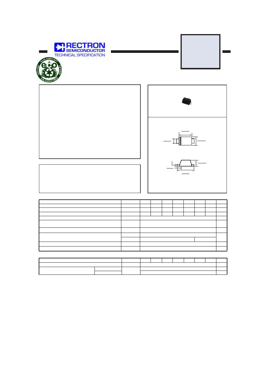
SA1
THRU
SA7
SOD-123F
MAXIMUM RATINGS
(@ T
A
=25
O
C unless otherwise noted)
ELECTRICAL CHARACTERISTICS
(@T
A
=25
O
C unless otherwise noted)
Dimensions in inches and (millimeters)
FEATURES
* Ideal for surface mounted applications
* Low leakage current
* Metallurgically bonded construction
* Mounting position: Any
* Weight: 0.016 gram
MECHANICAL DATA
* Epoxy : Device has UL flammability classification 94V-0
RATINGS
Maximum Recurrent Peak Reverse Voltage
Maximum RMS Voltage
Maximum DC Blocking Voltage
Maximum Average Forward Rectified Current at T
A
= 55
o
C
Peak Forward Surge Current I
FM
(surge): 8.3 ms single half sine-wave
superimposed on rated load (JEDEC method)
Typical Junction Capacitance (Note 1)
Typical Thermal Resistance (Note 3)
Current Squarad Time
Operating and Storage Temperature Range
SYMBOL
V
RRM
V
DC
I
O
I
R
q
JA
R
q
JL
FSM
I
2
t
C
J
T
J
, T
STG
V
RMS
Amps
1.0
25
2.5
85
25
30
-55 to + 150
pF
0
C
0
C/W
UNITS
Volts
Volts
SA1
SA3
SA2
SA4
SA6
SA5
SA7
50
100
200
400
600
800
1000
50
100
200
400
600
800
1000
35
70
140
280
420
560
700
Volts
Amps
A
2
/Sec
8
NOTES : 1. Measured at 1.0 MHz and applied average voltage of 4.0VDC
2010-05
REV:B
CHARACTERISTICS
V
F
SYMBOL
I
R
1.1
50
uAmps
Maximum Forward Voltage at 1.0A DC
Volts
U N I T S
Maximum DC Average Reverse Current at
Rated DC Blocking Voltage
@T
A
= 25
o
C
@T
A
= 100
o
C
SA1
SA3
SA2
SA4
SA6
SA5
SA7
5.0
uAmps
2. “Fully ROHS compliant”, “100% Sn plating (Pb-free)”.
3. Thernal Resistance: Mounted on PCB.
.150 (3.8)
.142 (3.6)
.035 (0.90)
.028 (0.70)
.053 (1.35)
.047 (1.20)
.077 (1.95)
.069 (1.75)
.030 (0.75)
.022 (0.55)
.008 (0.20)
.114 (2.9)
.106 (2.7)
4. Available in Halogen-free epoxy by adding suffix -HF after the part nbr.
SURFACE MOUNT SILICON RECTIFIER
VOLTAGE RANGE 50 to 1000 Volts CURRENT 1.0 Ampere