
1
GDTs, MOVs & Fuses:
Selecting the Appropriate
Circuit Protection Component
1
GDTs, MOVs & Fuses:
Selecting the Appropriate
Circuit Protection Component

2
Confidential and Proprietary to Littelfuse. Littelfuse, Inc. © 2014
PROTECT
|
CONTROL
|
SENSE
Introduction
Selecting the appropriate circuit protection
component is critical to a safe and robust design
Sometimes, selecting the incorrect component
can lead to catastrophic failures
This presentation will show examples of proper
and improper device selection and the
consequences

3
Confidential and Proprietary to Littelfuse. Littelfuse, Inc. © 2014
PROTECT
|
CONTROL
|
SENSE
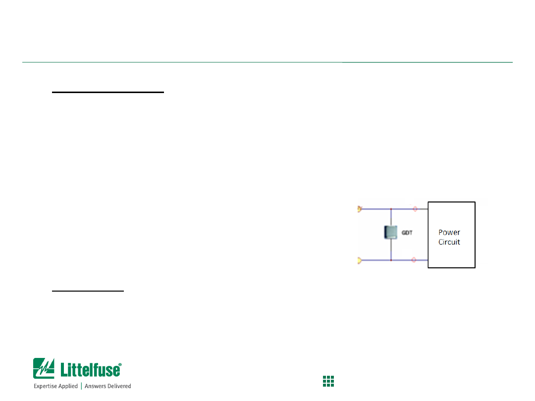
Glowing Reviews of the (Wrong) GDT
Background:
– Selecting the appropriate GDT for power line applications
Surge protection on AC or DC power lines is typically done by using MOVs
GDTs are typically used in signal applications or one N
– PE leg due to minimal
available currents
Problem
:
– Upon seeing overvoltage surge, GDTs will break-over (crow-bar) by
creating a sustained arc across the electrodes; surge current then shunted
to ground, usually.
– When surge event subsides, the GDT arc will be extinguished and system
will return to normal
– If power is applied to the line, the “follow current” will sustain the arc and
the GDT may not be able to turn off.
– GDT will then thermally fail due to sustained currents (glow red hot)
Solution:
– Littelfuse has AC power optimized GDTs (AC120/240 Series)
4
Confidential and Proprietary to Littelfuse. Littelfuse, Inc. © 2014
PROTECT
|
CONTROL
|
SENSE
Glowing Reviews of the (Wrong) GDT
Test Set-up:
– 120V tube, AC coupled, 6KV/3KA, limited to 10A
follow thru current
– Littelfuse AC120 GDT (designed for power lines)
– Littelfuse SL series GDT (designed for signal apps)
Images:
– 1. Littelfuse AC120 (GOOD) –
see next slide
– 2. Littelfuse SL series (BAD) –
see next slide
5
Confidential and Proprietary to Littelfuse. Littelfuse, Inc. © 2014
PROTECT
|
CONTROL
|
SENSE
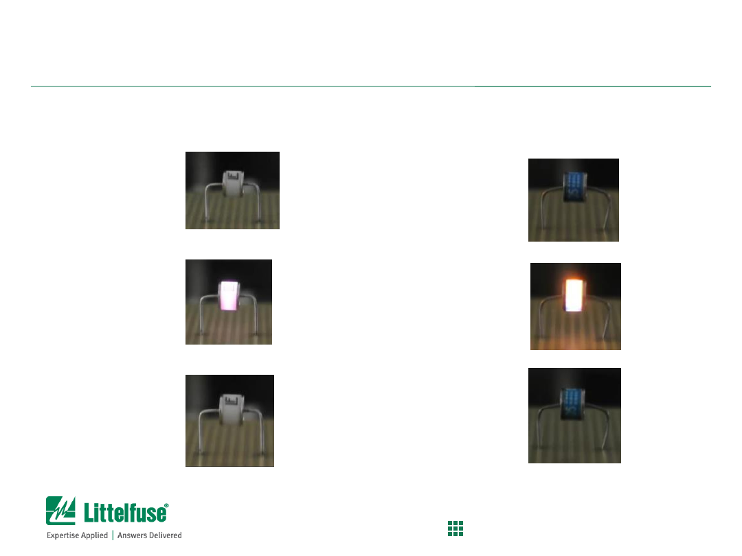
Images Before, During and After
Good
– Before
– During
– After
Bad
– Before
– During
(longer glow,
more heat)
– After
6
Confidential and Proprietary to Littelfuse. Littelfuse, Inc. © 2014
PROTECT
|
CONTROL
|
SENSE
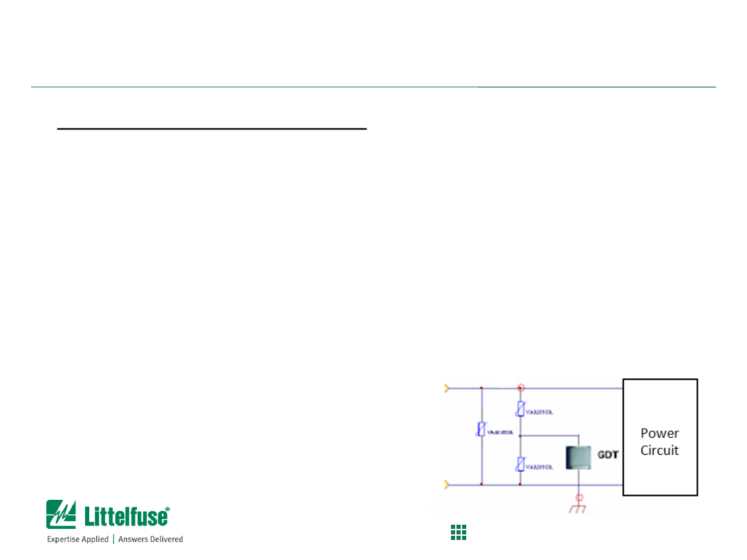
Glowing Reviews of the (Wrong) GDT
Additional Information:
MOVs can be placed in series with GDTs
MOV will help cut off the follow current and allow GDT to turn
off
During surge event, MOV will clamp and conduct first into a
low impedance state ; then GDT will break-over and create the
arc.
When surge subsides, the MOV will go back to high
impedance state and will quench the follow current and allow
GDT arc to be extinguished

7
Confidential and Proprietary to Littelfuse. Littelfuse, Inc. © 2014
PROTECT
|
CONTROL
|
SENSE
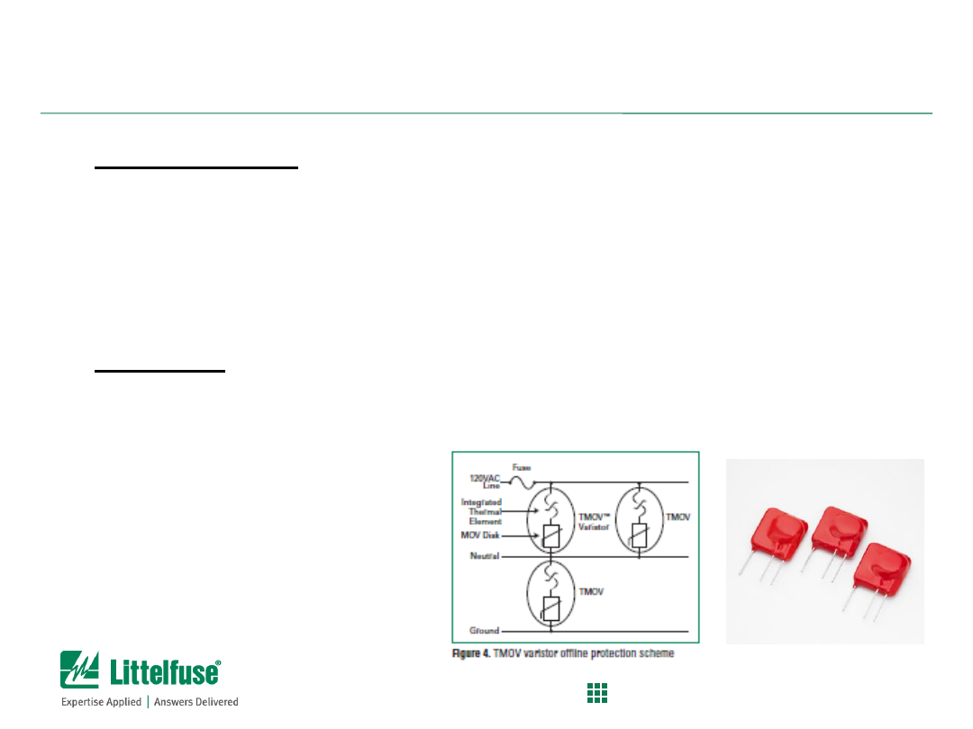
MOV End of Life Failures are Really HOT!
Background:
– MOV (Metal Oxide Varistors) can degrade over lifetime due to surge events
– MOV material can weaken due to multiple surges and develop “memory” path
– MOV at end-of-life will start to leak current with nominal system voltage applied
Problem:
– Leakage will heat up the MOV and impedance will continue to drop leading to
thermal run-away failure
– MOV protection solutions needing to meet UL1449 3
rd
Ed which includes
Abnormal Overvoltage testing which simulates this fault condition
Solution:
– Select Littelfuse TMOV series products to control MOV end-of-life (EOL)
conditions.
– TMOV™ MOVs have integrated thermal protector built inside the disc which
will open upon thermal heating of MOV.
– Use of TMOV will prevent catastrophic failure of MOV disc during EOL
condition
– TMOVs will help equipment makers pass UL1449 Abnormal Overvoltage
Limited Current test requirements without the need for external fuse
8
Confidential and Proprietary to Littelfuse. Littelfuse, Inc. © 2014
PROTECT
|
CONTROL
|
SENSE
MOV End of Life Failures are Really HOT!
Test Set-up:
– 150V MOV with 240V/10A fault, AC coupled – simulating EOL
condition
– Side-by-side testing 150V TMOV (thermally protected MOV)
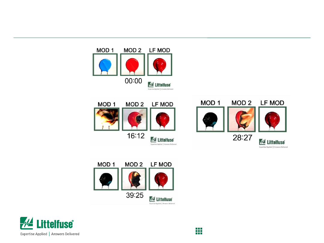
Images:
– Competitor MOV (Left) ; Littelfuse MOV (Middle) ; Littelfuse
TMOV (Right)
See next slide for before,
during & after pictures
9
Confidential and Proprietary to Littelfuse. Littelfuse, Inc. © 2014
PROTECT
|
CONTROL
|
SENSE
Images Before, During and After
– Before
– During
– After

10
Confidential and Proprietary to Littelfuse. Littelfuse, Inc. © 2014
PROTECT
|
CONTROL
|
SENSE
Don’t Let Your Diode Die an Untimely Death
Background:
– TVS diodes can be used for AC or DC input power protection
– Caution to stay under the surge rating of the TVS diode
– While TVS diodes offer fast and efficient clamping capability,
they have limited surge robustness
– IEC61000-4-5 and C.62.41-2002 are popular surge immunity
standards
– Maximum indoor surge condition typically is 6kV/3kA, 8/20us
surge combo wave
Problem:
– TVS diodes can undergo catastrophic failure if over stressed
beyond surge ratings
– Traces need to be sized according or will open up as well!
Solution:
– Select the correct TVS diode surge rating for your application
11
Confidential and Proprietary to Littelfuse. Littelfuse, Inc. © 2014
PROTECT
|
CONTROL
|
SENSE
Don’t Let Your Diode Die an Untimely Death
Test Set-up:
– SMCJ TVS diode, 1500W diode, bidirectional –
6kV/3kAa surge applied
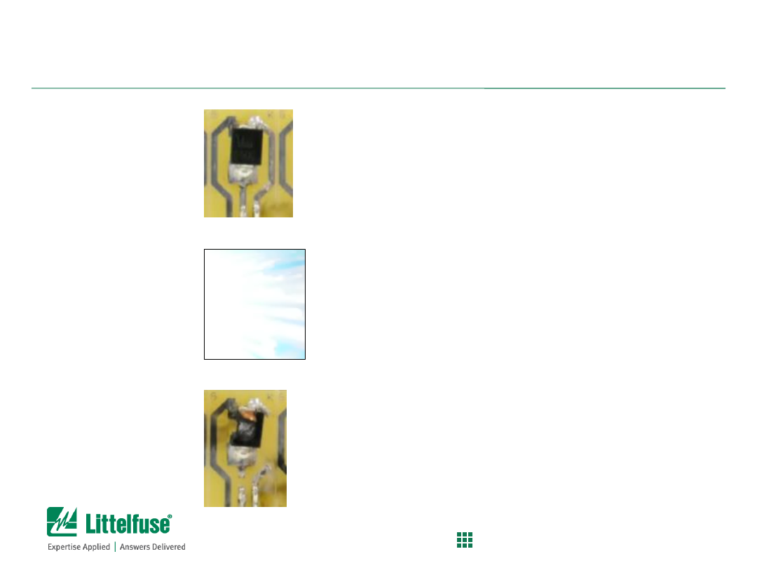
Images:
See next slide for before,
during & after pictures
12
Confidential and Proprietary to Littelfuse. Littelfuse, Inc. © 2014
PROTECT
|
CONTROL
|
SENSE
Images Before, During and After
– Before
– During
– After
13
Confidential and Proprietary to Littelfuse. Littelfuse, Inc. © 2014
PROTECT
|
CONTROL
|
SENSE
Additional Information:
– Diodes should be selected for a given application by their:
Power Rating,
Maximum surge current,
Standoff Voltage, and
Breakdown Voltage
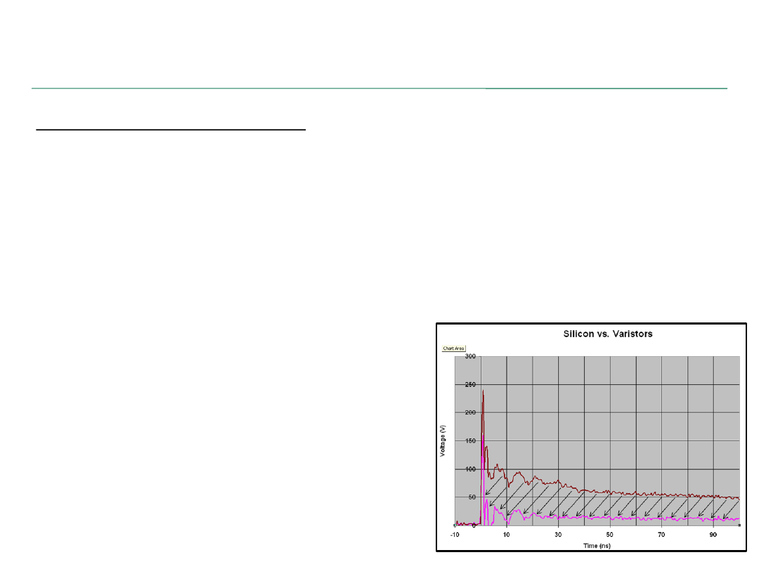
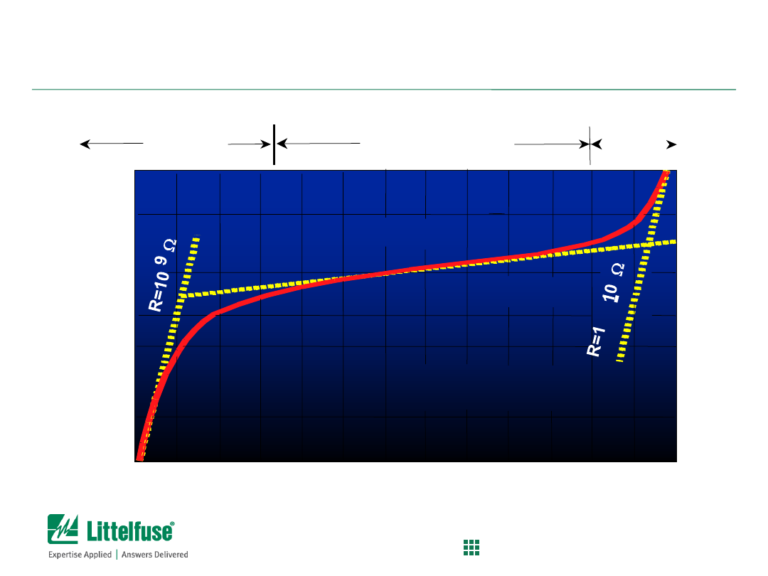
– Though sometimes not as robust as a MOV, a TVS Diode will have the
lowest dynamic resistance (the resistance between the I/O and ground);
therefore, a TVS Diode will clamp
better and reduce the overall amount
of energy seen by the sensitive electronics
downstream.
– The area between the curves represents
the amount of energy that DOES NOT
get to the chip when an MLV was
replaced by an equivalent TVS Diode
.
Don’t Let Your Diode Die an Untimely Death

14
Confidential and Proprietary to Littelfuse. Littelfuse, Inc. © 2014
PROTECT
|
CONTROL
|
SENSE
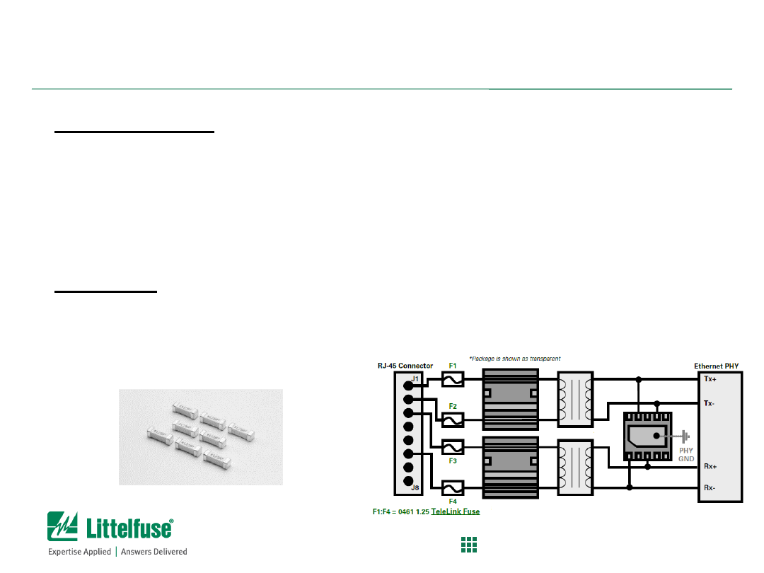
Ethernet Vs. Power Cross
Background:
– Ethernet ports needing to meet GR-1089 Inter-Building Power
Cross requirements need appropriate overcurrent protection
– Typically, protection is a surge tolerant fuse that will open fast
enough during Power cross testing
Problem:
– Prevent SEP SIDACtor (overvoltage protector) from getting
damaged during power cross testing
– Proper fusing required to comply with GR-1089 Power cross and
prevent equipment damage/safety hazard
Solution:
– Use Littelfuse 461 Series Telelink fuse (typically 1.25A rating) at
port input on cable side
– Use low capacitance, C or D Rated, SIDACtor overvoltage
protector (Littelfuse SEP series)
15
Confidential and Proprietary to Littelfuse. Littelfuse, Inc. © 2014
PROTECT
|
CONTROL
|
SENSE
Ethernet Vs. Power Cross
Test Set-up:
– Littelfuse Ethernet demo board - Power cross 425V/40A GR-1089
fault
– with and without fuse protection
– SEP Series Ethernet surge protector on cable side
– Fuse – Littelfuse 461 series, 1.25A Telelink fuse
Images:
– With fuse:
– Without fuse:
See next slide for before,
during & after pictures
16
Confidential and Proprietary to Littelfuse. Littelfuse, Inc. © 2014
PROTECT
|
CONTROL
|
SENSE
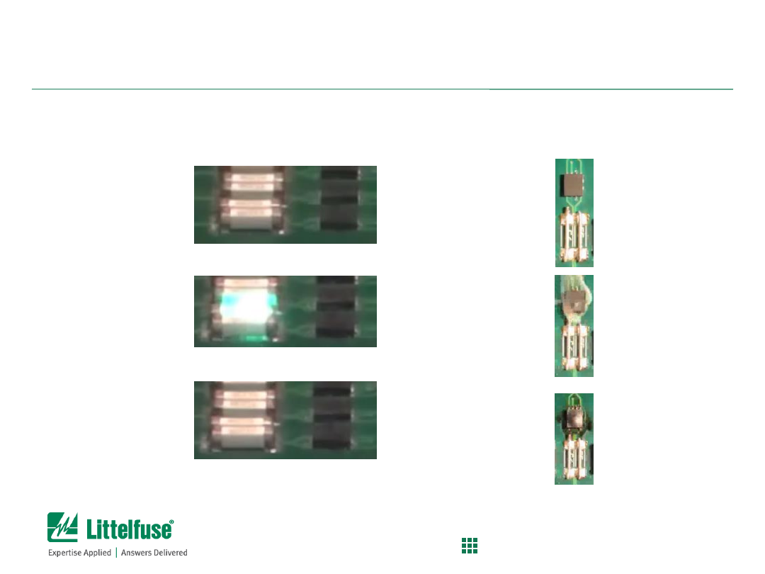
Images Before, During and After
With Fuse
– Before
– During
– After
Without Fuse
– Before
– During
– After

17
Confidential and Proprietary to Littelfuse. Littelfuse, Inc. © 2014
PROTECT
|
CONTROL
|
SENSE
“Fuse Interrupted” (the exploding DVD version)
Background:
– Fuse max voltage and max interrupt rating are safety
critical specifications
– When fuse opens during fault, the higher voltage applied
will cause arc to form longer duration
– Higher voltage and higher current faults will cause plasma
formation and molten metal
– Fuse body, fillers, and fuse element designed to quench
arc and safely open fuse
Problem:
– Deviating from fuse max specs and over-stressing the
device will cause catastrophic failures
Solution:
– Stay under the fuse voltage and interrupt ratings

18
Confidential and Proprietary to Littelfuse. Littelfuse, Inc. © 2014
PROTECT
|
CONTROL
|
SENSE
“Fuse Interrupted” (the exploding DVD version)
Test Set-up:
– Littelfuse 215 series, 5x20mm ceramic fuse ; 3.15A rating ;
250VAC/1500A Interrupt rating
– We applied 250VAC/1500A short circuit fault
– We applied 400VDC, 200A short circuit fault (above fuse voltage
rating)
Images:
Within fuse voltage rating:
Above fuse voltage rating:
See next slide for before,
during & after pictures
19
Confidential and Proprietary to Littelfuse. Littelfuse, Inc. © 2014
PROTECT
|
CONTROL
|
SENSE
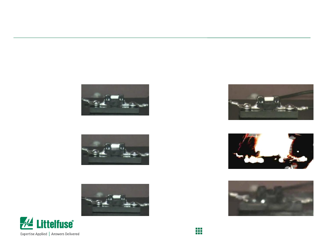
Images Before, During and After
Within Fuse Voltage
Rating
– Before
– During
– After
Above Fuse Voltage
Rating
– Before
– During
– After

20
Confidential and Proprietary to Littelfuse. Littelfuse, Inc. © 2014
PROTECT
|
CONTROL
|
SENSE
The Non-Resettable Resettable Fuse
Background:
– Just like fuses, PTC Resettable fuses can experience
overvoltage stress and fail
– PTC’s most dangerous failure mode is overvoltage stress
– The higher voltage causes damage to the polymer material and
will damage the conductive carbon particles
Problem:
– Choosing wrong voltage rating can lead to catastrophic failure
mode
Solution:
– Stay under the max voltage rating of your PTC

21
Confidential and Proprietary to Littelfuse. Littelfuse, Inc. © 2014
PROTECT
|
CONTROL
|
SENSE
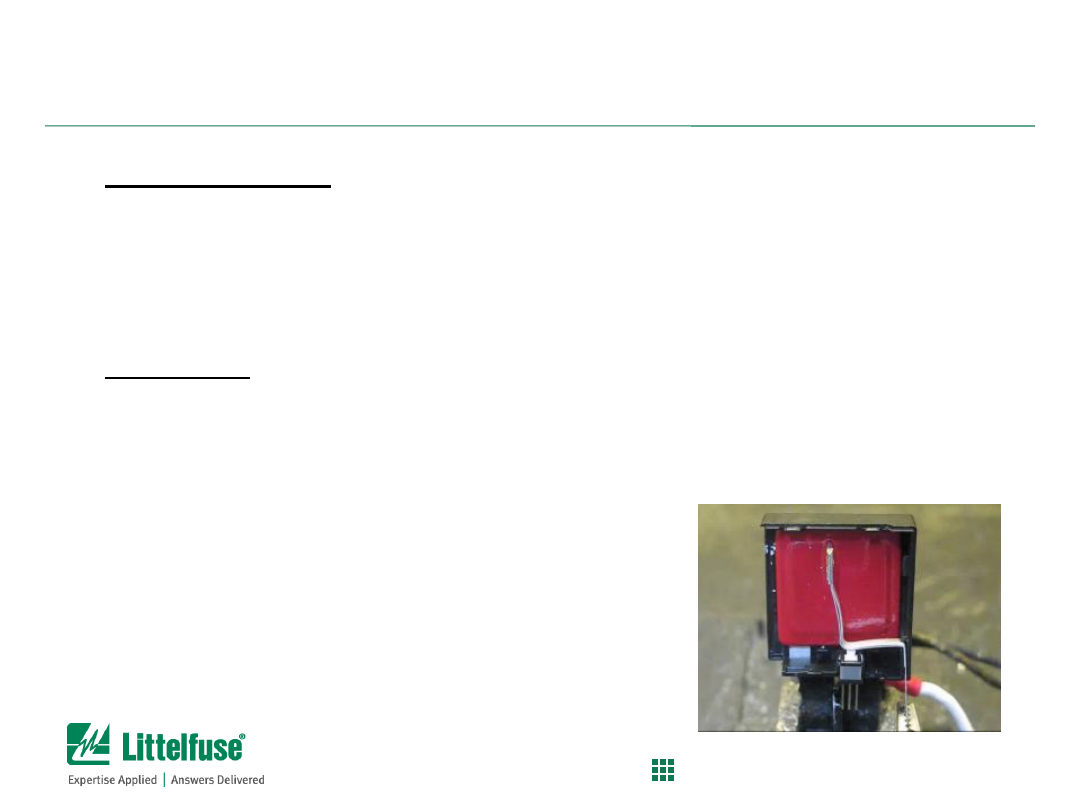
See next slide for before,
during & after pictures
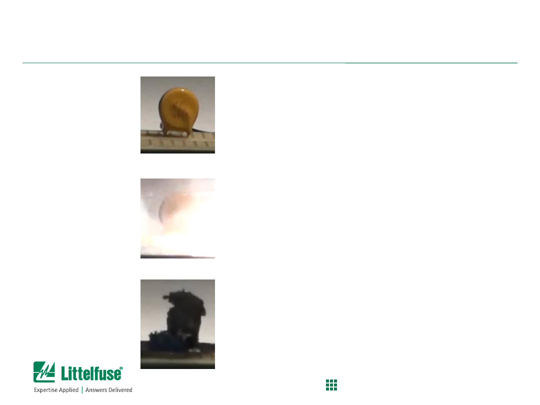
The Non-Resettable Resettable Fuse
Test Set-up:
– Littelfuse 16R series PTC Resettable fuse being used
in 60VDC short circuit fault
– 16R series has max voltage rating of 16VDC
– Littelfuse 60R or 72R series is recommended for this
application.
Images:
22
Confidential and Proprietary to Littelfuse. Littelfuse, Inc. © 2014
PROTECT
|
CONTROL
|
SENSE
Images Before, During and After
– Before
– During
– After

23
Confidential and Proprietary to Littelfuse. Littelfuse, Inc. © 2014
PROTECT
|
CONTROL
|
SENSE
Fusible Resistors are Irresistible (buyer beware!)
Background:
– Fusible resistors are poor alternatives to using a properly specified
fuse.
– These fusible resistors are frequently used in LED bulb or charger
applications due to their low cost.
– FusR will tend to get very hot during overload and burn open
causing potential safety hazard.
– Smoke will be generated from burning fusible resistor which is a
customer satisfaction issue.
Problem:
– Unlike a fuse which is designed to open safely during overload
condition, a fusible resistor (FusR) will not have a controlled and
consistent opening mode.
Solution:
– Select a Littelfuse fuse designed to meet the specified
requirements.
24
Confidential and Proprietary to Littelfuse. Littelfuse, Inc. © 2014
PROTECT
|
CONTROL
|
SENSE
Fusible Resistors are Irresistible (buyer beware!)
Test Set-up:
– Fusible resistor vs. fuse during overload condition
– 392 series TE fuse vs. 10ohm FusR
– 240vac, 200% Overload over the fuse rating
Images:
– 392 series fuse – GOOD
– 10 Ohm Fusible resistor – BAD
See next slide for before,
during & after pictures
25
Confidential and Proprietary to Littelfuse. Littelfuse, Inc. © 2014
PROTECT
|
CONTROL
|
SENSE
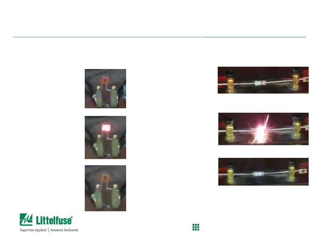
Images Before, During and After
Fuse
– Before
– During
– After
Fusible Resistor
– Before
– During
– After

26
Confidential and Proprietary to Littelfuse. Littelfuse, Inc. © 2014
PROTECT
|
CONTROL
|
SENSE
SMOV
– The Superhero of MOVs
Background:
– UL1449 3
rd
Ed, Abnormal Overvoltage Intermediate current
testing requires up to 150A fault current when testing MOVs
– Intermediate current testing required for Type 3 SPDs and
above.
Problem:
– Passing the UL1449 Intermediate current test standards typically
requires an external fuse
– Fuse will open before MOVs fail but difficult to select due to
6kv/3ka high surge withstand requirements
– Integrated thermal protection inside Littelfuse TMOV is limited to
max 10A fault current
Solution:
– Select Littelfuse SMOV Series instead of TMOV to pass UL1449
Intermediate current requirements
27
Confidential and Proprietary to Littelfuse. Littelfuse, Inc. © 2014
PROTECT
|
CONTROL
|
SENSE
See next slide for before,
during & after pictures
Test Set-up:
– 150V TMOV and SMOV tested at 240VAC/150A Intermediate
current per UL1449
Images:
– TMOV failing at 150A – BAD
– SMOV opening safely at 150A – GOOD
SMOV
– The Superhero of MOVs
28
Confidential and Proprietary to Littelfuse. Littelfuse, Inc. © 2014
PROTECT
|
CONTROL
|
SENSE
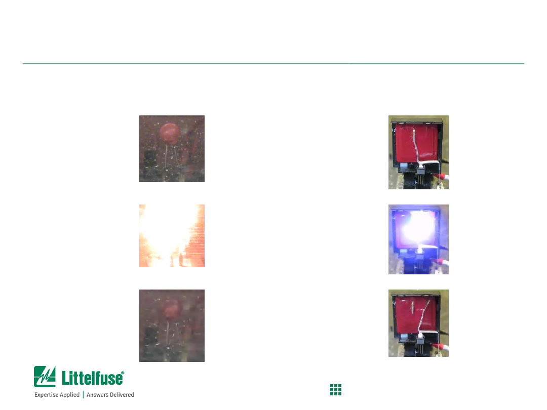
Images Before, During and After
TMOV
– Before
– During
– After
SMOV
– Before
– During
– After

29
Confidential and Proprietary to Littelfuse. Littelfuse, Inc. © 2014
PROTECT
|
CONTROL
|
SENSE
Selecting a Fuse

30
Confidential and Proprietary to Littelfuse. Littelfuse, Inc. © 2014
PROTECT
|
CONTROL
|
SENSE
Background selection information:
Maximum operating current
– the maximum current that the fuse will experience during normal
operation of the application
Ambient temperature
– the temperature in the area surrounding the fuse
Normal operating voltage
– the voltage level of the line that the fuse is protecting; this is also the
voltage that the fuse will have to safely support after it has opened
Current pulses
– these are short duration pulses for which the fuse should not open
• In-rush and start-up currents are examples
• The shape, magnitude and quantity of the pulses is needed to ensure no nuisance tripping
of the fuse
Maximum fault current
– this determines the Interrupt Rating (Breaking Capacity) that the fuse
must meet
Mounting requirements of fuse (surface mount, through hole) is considered secondary selection
criteria (to meet mechanical needs)
Fuse Selection Process
Basics
– definitions for selecting fuses

31
Confidential and Proprietary to Littelfuse. Littelfuse, Inc. © 2014
PROTECT
|
CONTROL
|
SENSE
Step 1) Collect information to calculate minimum fuse rating
• Maximum operating current
• Normal operating voltage
• Ambient temperature
Minimum fuse rating =
Maximum operating current
fuse re-rating factor x thermal de-rating factor
Use the following equation to calculate the minimum fuse rating:
Fuse Selection Process
Process for calculating minimum fuse current rating (Amps)
(This is explained in the Littelfuse Catalog starting on page 9)
32
Confidential and Proprietary to Littelfuse. Littelfuse, Inc. © 2014
PROTECT
|
CONTROL
|
SENSE
Fuse re-rating factor:
• Use 0.75 if the fuse is UL or CSA Listed or Recognized
• Use 1.00 if the fuse is IEC Designed
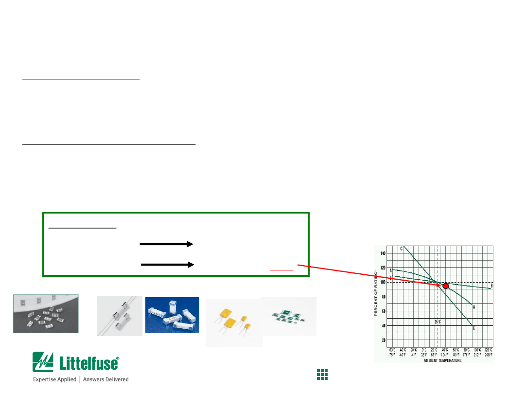
Thermal de-rating factor (TDR):
Determine the thermal de-rating factor by using the appropriate curve for the ambient
temperature that the fuse will experience (found on page 9 of Fuse Catalog)
Curve A = Thin Film Fuses
Curve B = Wire-in-air Fuses
•
(Cartridge, Nano
2
)
Curve C = Resettable PTCs
For example:
Thin Film Fuse
Use Curve A
If temp is 40ºC
Use TDR of
95%
Chip fuses
Wire-in-air fuses
Fuse Selection Process
Process for calculating minimum fuse rating (amperage)
Resettable PTCs

33
Confidential and Proprietary to Littelfuse. Littelfuse, Inc. © 2014
PROTECT
|
CONTROL
|
SENSE
maximum operating current
fuse re-rating factor x thermal de-rating factor
For this example, it is given that a
surface mount thin film fuse
is desired, and that the
maximum operating current is 0.50A and ambient temperature is 40
°
C:
Maximum operating current:
0.50A
Fuse re-rating factor:
0.75
Thermal de-rating factor:
0.95
Then, minimum fuse rating =
=
0.700 A
Since this value is the minimum requirement, find the closest fuse rating that is higher.
So, the minimum fuse rating that can be used is
0.750 A.
0.50 A
0.75 x 0.95
Step 2) Calculate the minimum fuse rating
Minimum fuse rating =
Fuse Selection Process
Process for calculating minimum fuse rating (amperage)
34
Confidential and Proprietary to Littelfuse. Littelfuse, Inc. © 2014
PROTECT
|
CONTROL
|
SENSE
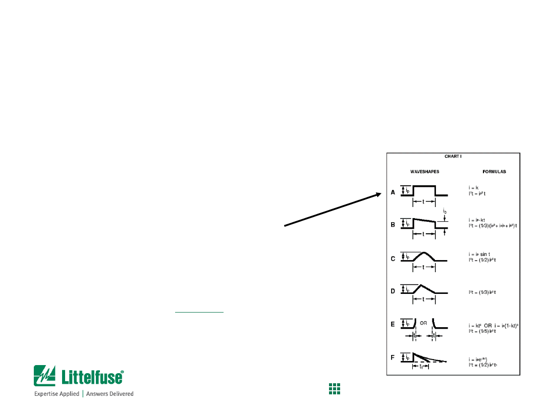
Step 3) Calculate minimum nominal melting I
2
t rating of fuse
1)
Determine
Pulse I
2
t
of the application (in-rush current, inductive load switching, etc.)
2)
Calculate nominal melting I
2
t of the fuse
Pulse I
2
t
:
use the waveshape chart to determine appropriate formula
For example:
• Assume that current measurements show
Type A waveshape
• Peak current was measured to be
1.5A
• Duration of pulses are
1 millisecond
.
Then,
Pulse I
2
t
= Ip
2
x t = (1.5)
2
x 0.001s =
0.00225 A
2
s
Fuse Selection Process
Process for calculating minimum melting i
2
t of fuse
35
Confidential and Proprietary to Littelfuse. Littelfuse, Inc. © 2014
PROTECT
|
CONTROL
|
SENSE
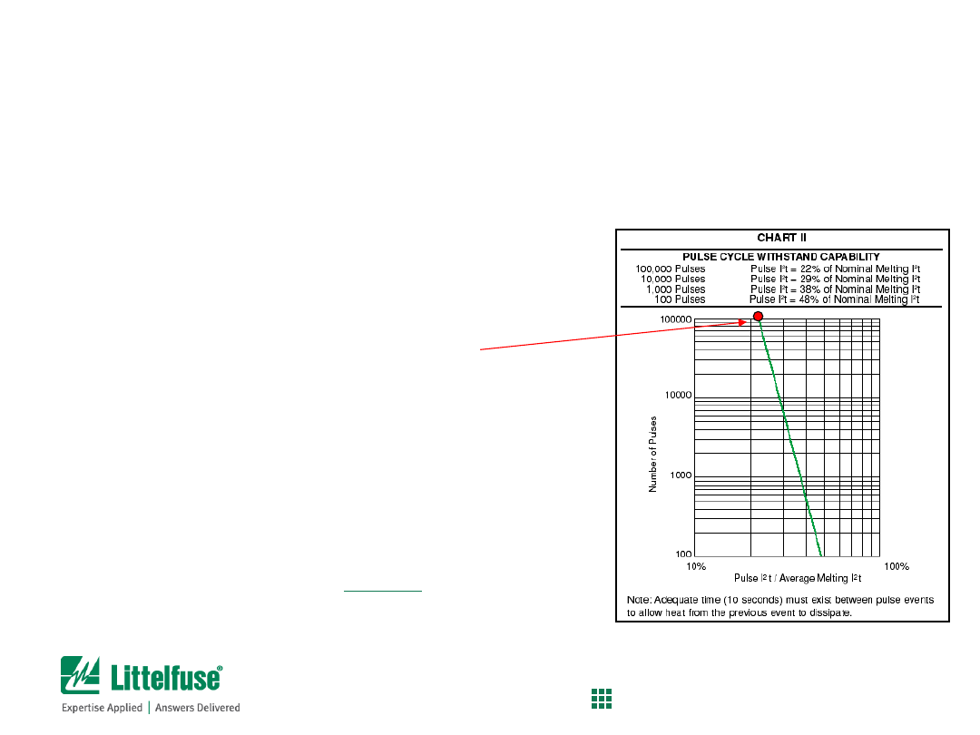
Step 4) Calculate minimum nominal melting I
2
t rating of fuse
1)
Determine
Pulse I
2
t
of the application
2)
Determine Rating Factor for the application
For example:
•
Pulse
Pulse I
2
t
was calculated to be
0.00225 A
2
s
•
Assume that the fuse needs to survive
100,000 pulses
Use Chart II to determine the Rating Factor
•
For 100,000 pulses,
Rating Factor is 22%
Then,
Minimum
nominal melting
I
2
t
rating = Pulse I
2
t / rating factor
= 0.00225 A
2
s / 0.22
=
0.0102 A
2
s
Fuse Selection Process
Process for calculating minimum melting i
2
t of fuse
36
Confidential and Proprietary to Littelfuse. Littelfuse, Inc. © 2014
PROTECT
|
CONTROL
|
SENSE
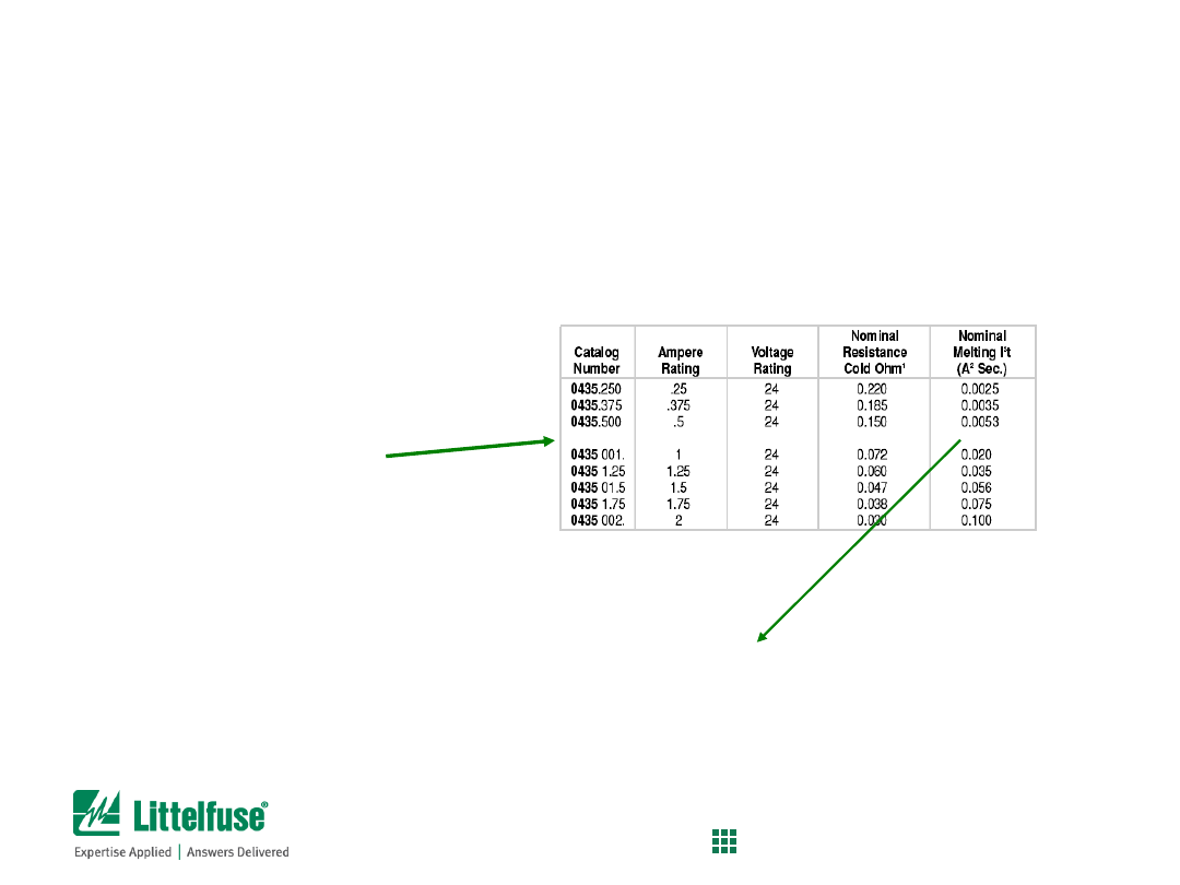
Step 5) Compare the calculated nominal melting I
2
t to actual fuses:
Surface mount thin film fuses were specified earlier
So, compare Nominal melting
I
2
t
value of 0.750A-rated thin film fuses to target value (0.0102 A
2
s):
0433.750
1206, very fast acting
0.0170 A
2
s
63VDC
0434.750
0603, very fast acting
0.0171 A
2
s
32VDC
0435.750
0402, very fast acting
0.0120 A
2
s
24VDC
0435.750 .75 24 0.105 0.0120
Since the nominal melting
I
2
t
value for all of these fuses is
greater than
the required value of the
application (0.0102 A
2
s), they are all valid for usage. The specific part can be chosen according the
amount of board space available, the rated voltage, etc.
The information can be found on
the product data sheet. The
chart to the right is for the
SlimLine 0402, 0435 series fuse.
Fuse Selection Process
Process for calculating minimum melting i
2
t of fuse
37
Confidential and Proprietary to Littelfuse. Littelfuse, Inc. © 2014
PROTECT
|
CONTROL
|
SENSE
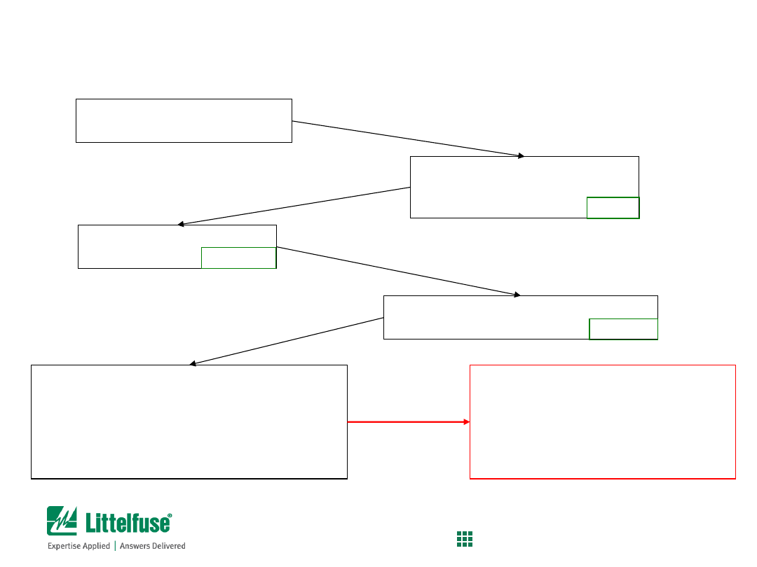
Understand the application
and circuit parameters
Compare calculated and actual nominal
melting
I
2
t
values to ensure fuse will not suffer
nuisance opening. If there are multiple fuses
qualified for the application, use secondary
characteristics (size, voltage rating, etc.) to
determine best solution
Determine minimum current
rating of fuse (fuse re-rating,
thermal de-rating)
0.750 A
Determine minimum
Nominal melting
I
2
t
value of the Fuse
0.0102 A
2
s
Determine
Pulse I
2
t
value
of the application
0.00225 A
2
s
IMPORTANT!! Even though care may
be used during the fuse selection
process, it is recommended that
application-level testing be performed
to verify coordination of fuses to the
circuit conditions
Fuse Selection Process
Summary of steps to select fuse
38
Confidential and Proprietary to Littelfuse. Littelfuse, Inc. © 2014
PROTECT
|
CONTROL
|
SENSE
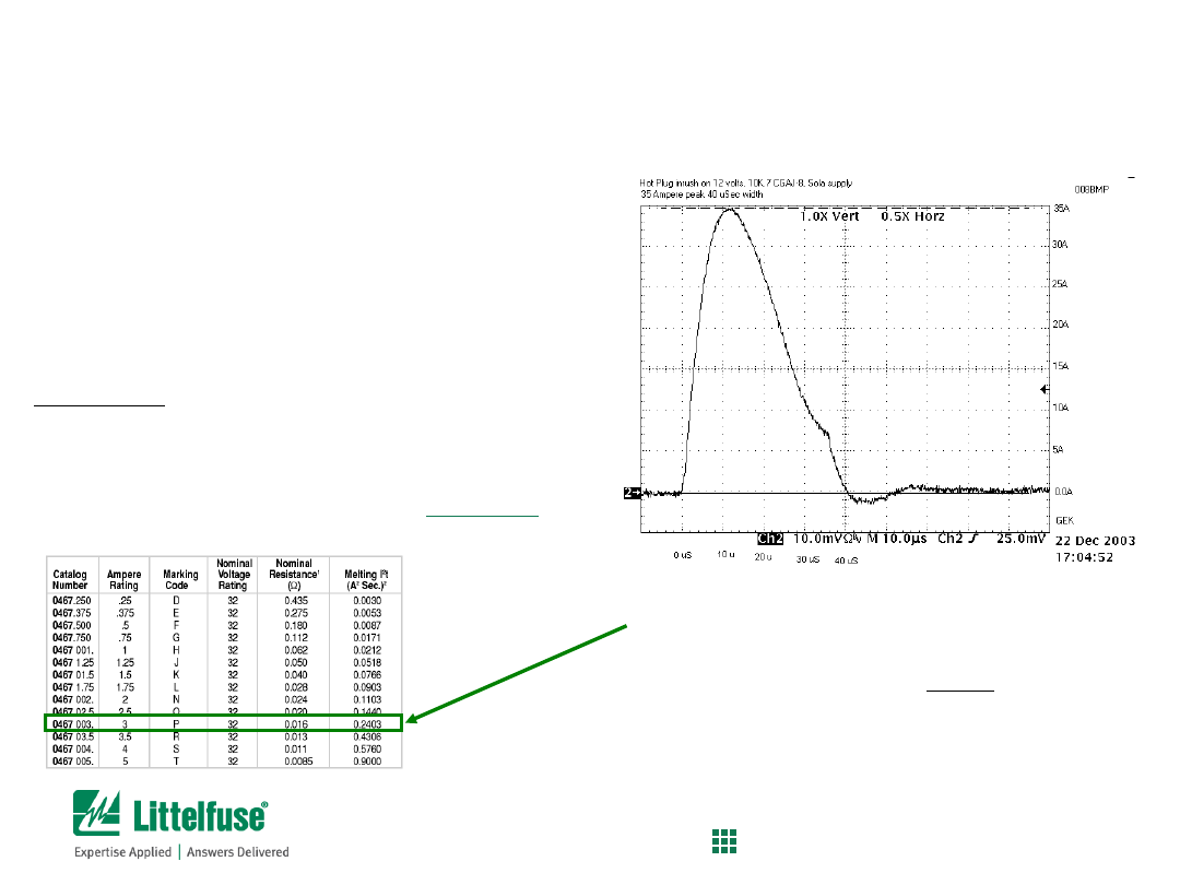
Details of in-rush current
• System voltage = 12VDC
• Peak current = 35A
• t = 40
s
• Number of pulses required = 70,000
Calculations:
I
2
t = (1/2)Ip
2
t
I
2
t = (1/2) x (35A)
2
x (.00004)
Pulse I
2
t = 0.0245 A
2
s
Nominal melting I
2
t = (0.0245 / 0.23) =
0.1065 A
2
s
The 0467003.NR fuse had been selected
•
0.2403 A
2
s
is the listed value
• This value is greater than the
calculated value, so the fuse should
withstand 70,000 pulses
•
Testing at Littelfuse confirmed that
the fuse could indeed survive 70,000
of these pulses
Fuse Selection Example
Verification of calculated melting i
2
t
Screen shot is actual in-rush current from HDD hot-plug
39
Confidential and Proprietary to Littelfuse. Littelfuse, Inc. © 2014
PROTECT
|
CONTROL
|
SENSE
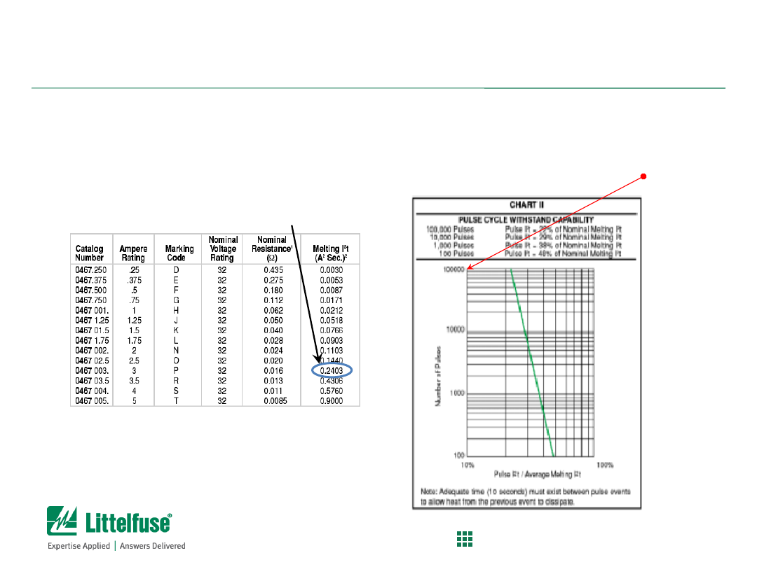
Pulse Energy vs. Fuse Melting Energy
Calculated Pulse I
2
t = 0.0245 A
2
s
(previous page)
0467003 Fuse I2t = 0.2403 A
2
s
Ratio of Calculated Pulse I
2
t / Fuse Melting I
2
t
= 0.0245 A
2
s / 0.2403 A
2
s = ~10.2%
>100,000
pulses at 10.2%
melting I²t
Fuse Selection Example (continued)
Using Ratio of Calculated Pulse I
2
t to Melting I
2
t of selected fuse to
determine Pulse Cycle Withstand Capability

40
Confidential and Proprietary to Littelfuse. Littelfuse, Inc. © 2014
PROTECT
|
CONTROL
|
SENSE
Surge Protection Selection
- Metal Oxide Varistor
41
Confidential and Proprietary to Littelfuse. Littelfuse, Inc. © 2014
PROTECT
|
CONTROL
|
SENSE
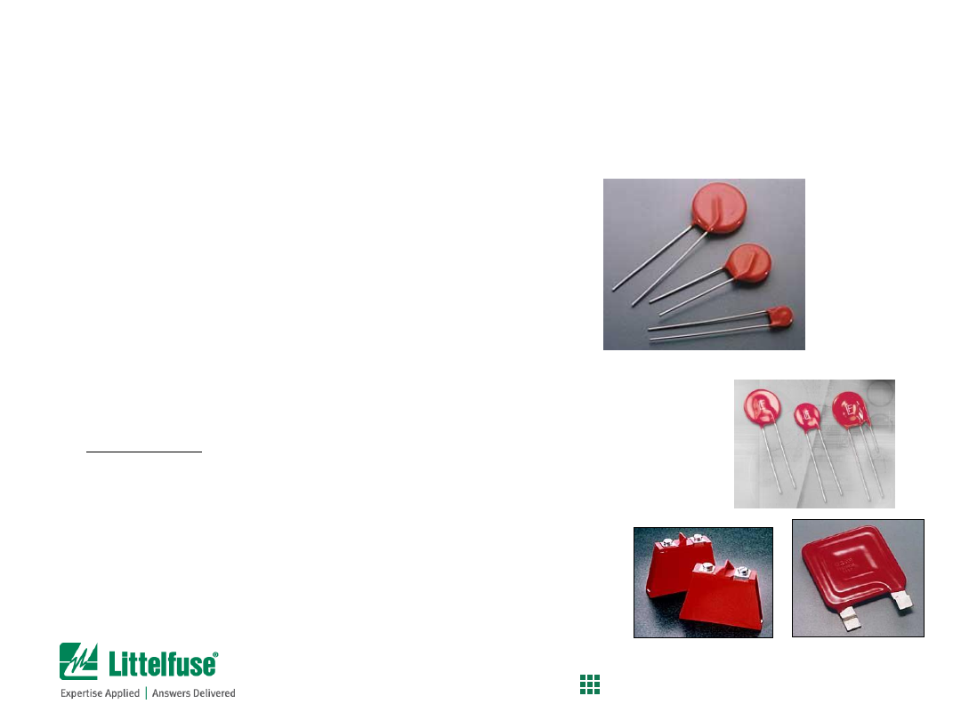
Metal Oxide Varistor (MOV)
•
Shunts high pulse-current and high-energy
transients to ground; thereby protecting the
application
•
Industry standard form factors
•
Thermally-protected version is available (TMOV)
•
Key feature is the durability to repeatedly
handle high peak pulse current, high-energy
surge transients
Surge Protection Component
Overview of MOV product
42
Confidential and Proprietary to Littelfuse. Littelfuse, Inc. © 2014
PROTECT
|
CONTROL
|
SENSE
-
10
-8
10
-6
-
10
-2
10
0
10
2
10
4
Current (A)
Leakage
Region
Normal Varistor
Operation
Upturn
Region
V
oltage
(
V)
SLOPE =
1
a
I = kV
a
10
20
50
100
200
500
1000
(TYPICAL V130LA2OA)
10
-4
Surge protection component
Functional regions of MOV (based on V-I curve)

43
Confidential and Proprietary to Littelfuse. Littelfuse, Inc. © 2014
PROTECT
|
CONTROL
|
SENSE
Surge Protection Selection
- Metal Oxide Varistor
- Example of selecting a MOV

44
Confidential and Proprietary to Littelfuse. Littelfuse, Inc. © 2014
PROTECT
|
CONTROL
|
SENSE
Example of MOV selection
Circuit conditions and requirements:
-120VAC circuit
- Current waveform for surge is 8x20
s; voltage is 1.2x50µs
- Peak current during the surge is 3,000A
- Requirement is to survive 40 surges
- Other components (transformer, capacitors, etc.) are rated to
withstand 1,000V maximum.
Approach to finding a solution:
- To find the voltage rating of the MOV, allow for 20% head room
to take into account voltage swells.
• 120VAC x 1.2 = 144VAC
• So look at 150VAC rated MOVs
• Determine which MOV disc size to use – identify those
that minimally meet the 3,000A surge requirement
-Use
Pulse Rating Curves
to determine pulse capabilities of
each series per the 40 pulses @ 3,000A requirement
- Use
V-I Curve
of selected MOV to verify that the peak voltage
will be below the 1,000V ceiling.
MOV Selection Process
Example of selecting a MOV for lightning protection
45
Confidential and Proprietary to Littelfuse. Littelfuse, Inc. © 2014
PROTECT
|
CONTROL
|
SENSE
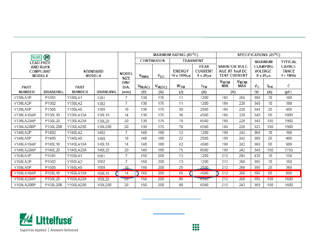
MOV Selection Process
Determine which disc size is needed
(see page 112 of MOV Catalog)
Data sheet review
– Peak Current rating
• From the problem statement, need > 3,000A capability for 150VAC disc
• Per the table, the 14mm disc can pass at least one 3,000A surge pulse
• Since the LA series is the least robust, we’ll start the evaluation there

46
Confidential and Proprietary to Littelfuse. Littelfuse, Inc. © 2014
PROTECT
|
CONTROL
|
SENSE
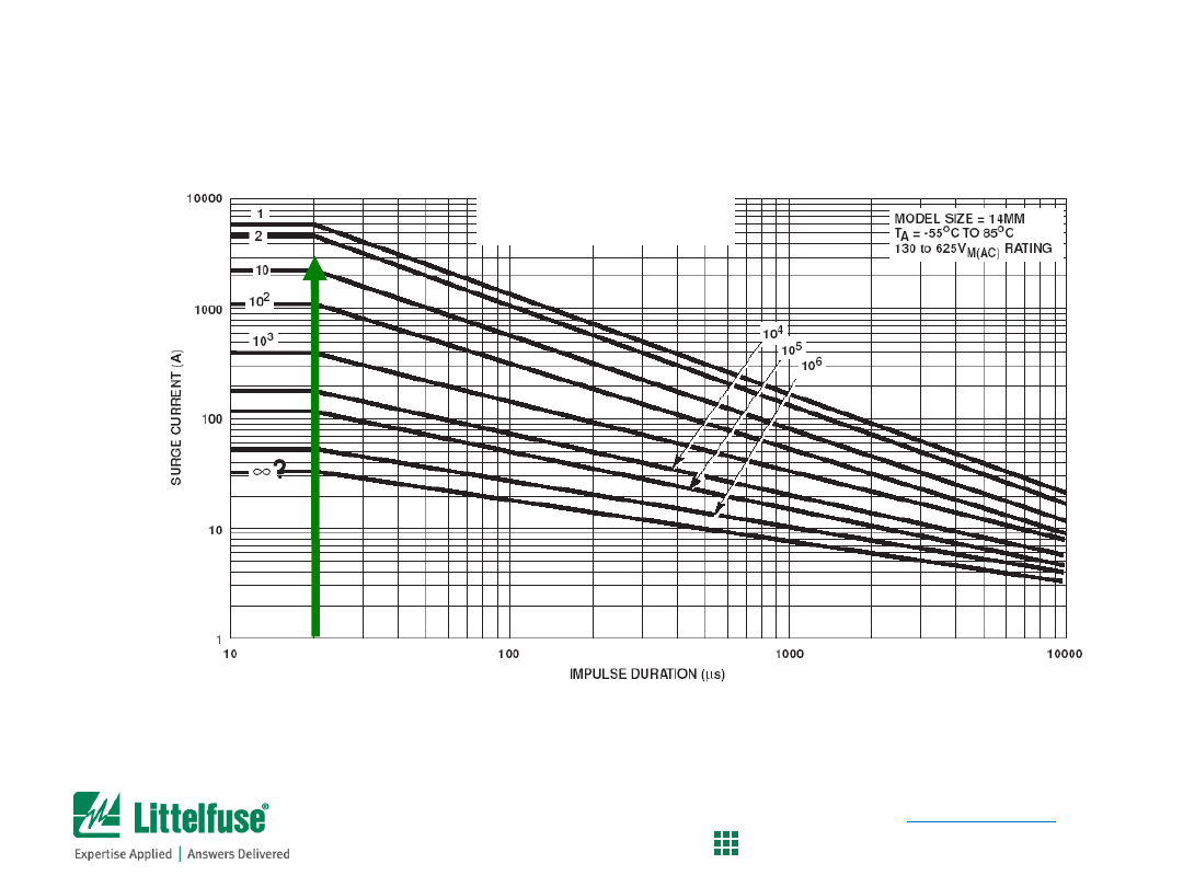
LA Series
Pulse Rating Curves for 14mm LA series
• Locate pulse width (20µs) on the x-axis
• Find where vertical line intercepts 3,000A point
• In this case, we find that the LA MOV can survive 1 to 2 pulses
MOV Selection Process
Determine if 14mm LA Series is suitable
(see page 117, Fig 11 of the MOV Catalog)
47
Confidential and Proprietary to Littelfuse. Littelfuse, Inc. © 2014
PROTECT
|
CONTROL
|
SENSE
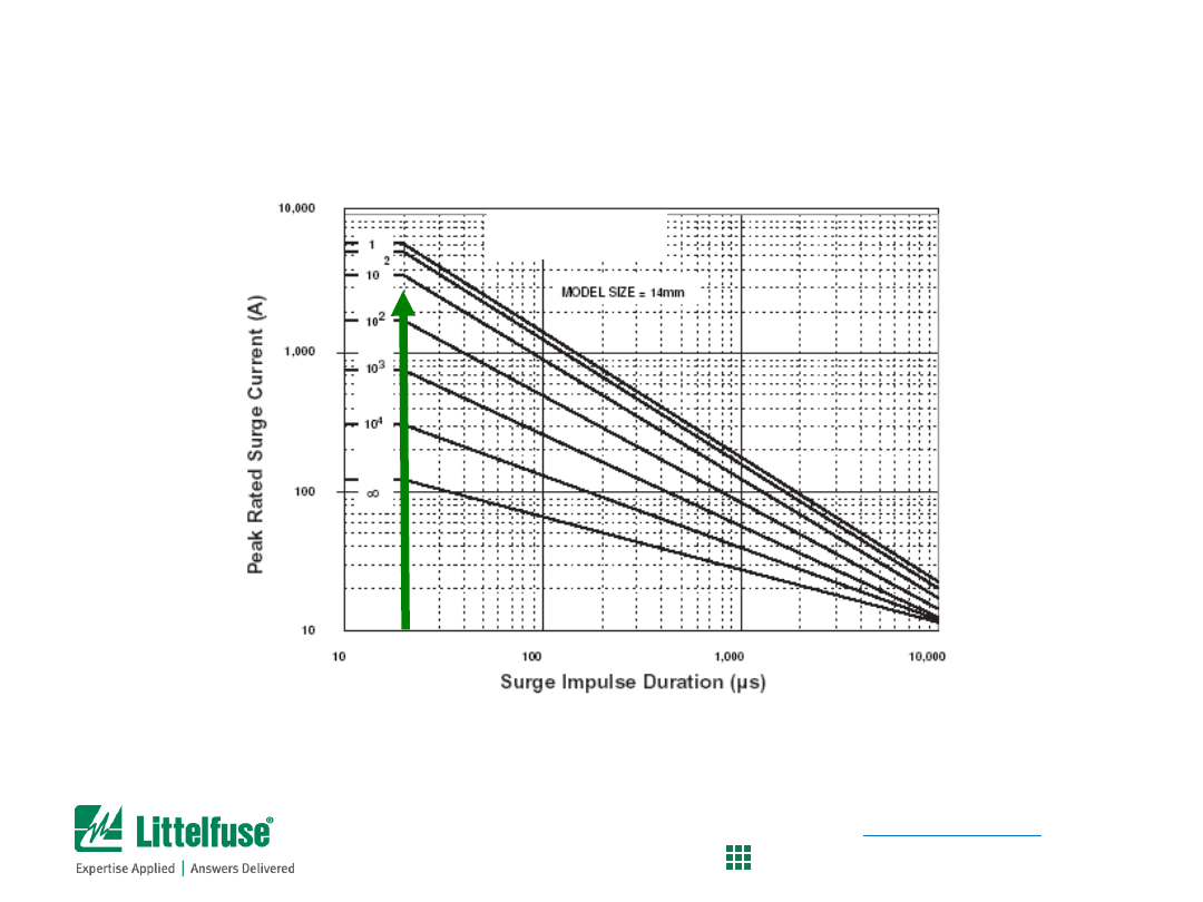
UltraMOV Series
Pulse Rating Curves for 14mm UltraMOV series
• Locate pulse width (20µs) on the x-axis
• Find where vertical line intercepts 3,000A point
• In this case, we find that the UltraMOV can survive 2 to 10 pulses
MOV Selection Process
Determine if 14mm UltraMOV Series is suitable
(see page 88, Fig 9 of the MOV Catalog)
48
Confidential and Proprietary to Littelfuse. Littelfuse, Inc. © 2014
PROTECT
|
CONTROL
|
SENSE
Pulse Rating Curves for 14mm C-III series
• Locate pulse width (20µs) on the x-axis
• Find where vertical line intercepts 3,000A point
• In this case, we find that the C-III can survive 10 to 100 pulses
C-III Series
MOV Selection Process
Determine if 14mm C-III Series is suitable
(see page 105, Fig 6 of the MOV Catalog)
49
Confidential and Proprietary to Littelfuse. Littelfuse, Inc. © 2014
PROTECT
|
CONTROL
|
SENSE
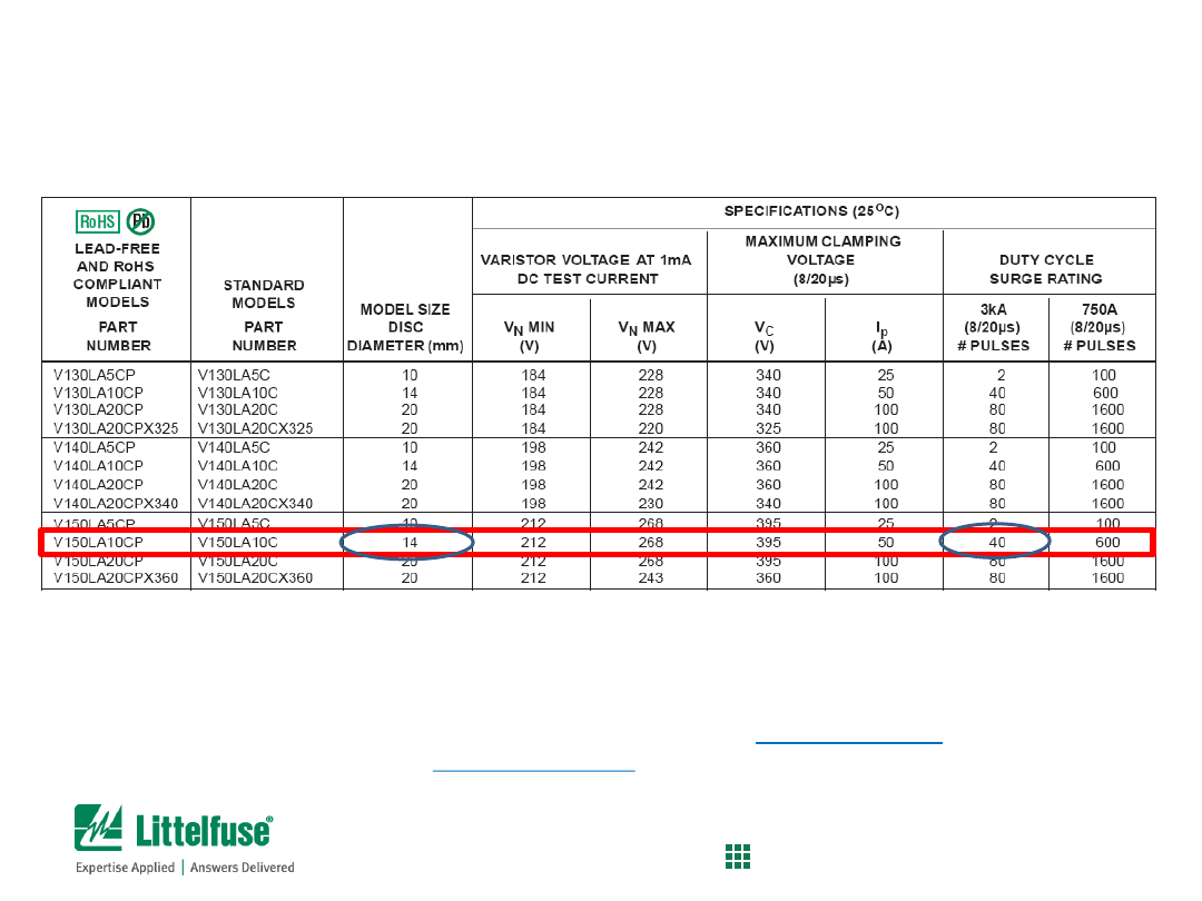
MOV Selection Process
So, how many pulses can 14mm C-III varistor take?
(see page 103 of the MOV Catalog)
Pulse Rating Curves for 14mm C-III series
• Consult the data sheet for verification of surge pulse capabilities
• From the table, the 14mm disc can survive 40 pulses
• So, the V150LA10C(P) is the best part for the requirements

50
Confidential and Proprietary to Littelfuse. Littelfuse, Inc. © 2014
PROTECT
|
CONTROL
|
SENSE
MOV Selection Process
Determine the peak voltage that the 3,000A surge will create
(see page 105 of the MOV Catalog)
V-I Curves for 14mm C-III series
• Consult the data sheet for verification of surge pulse capabilities
• From the table, locate the peak current on the x-axis (3,000A)
• Find where it intercepts the curve for V150LA10C(P) product
• In this case, the maximum voltage is found to be 850V

51
Confidential and Proprietary to Littelfuse. Littelfuse, Inc. © 2014
PROTECT
|
CONTROL
|
SENSE
Example of MOV selection
Circuit conditions and requirements:
-120VAC circuit
- Current waveform for surge is 8x20
s; voltage is 1.2x50µs
- Peak current during the surge is 3,000A
- Requirement is to survive 40 surges
- Other components (transformer, capacitors, etc.) are rated to
withstand 1,000V maximum.
Approach to finding a solution:
- To find the voltage rating of the MOV, allow for 20% head room
to take into account voltage swells.
• 120VAC x 1.2 = 144VAC
• So look at 150VAC rated MOVs
• Determine which MOV disc size to use – identify those
that minimally meet the 3,000A surge requirement
-Use
Pulse Rating Curves
to determine pulse capabilities of
each series per the 40 pulses @ 3,000A requirement
- Use
V-I Curve
of selected MOV to verify that the peak voltage
will be below the 1,000V ceiling.
MOV Selection Process
Compare V150LA10C(P) to requirements
Compare requirements to
V150LA10C(P)
Voltage rating of 150VAC
Disc size of 14mm
Can meet 40 surge pulses
Peak voltage of 850V
52
Confidential and Proprietary to Littelfuse. Littelfuse, Inc. © 2014
PROTECT
|
CONTROL
|
SENSE
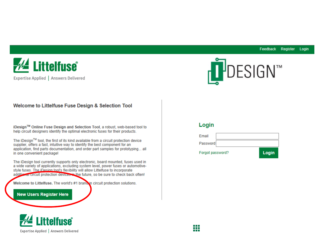
iDesign
TM
Online Fuse Design and Selection Tool
Registration page
Free to register now !!!
https://littelfuse.transim.com/login.aspx

53
Confidential and Proprietary to Littelfuse. Littelfuse, Inc. © 2014
PROTECT
|
CONTROL
|
SENSE
Additional Literature
Design and Selection Guides
Electronic Products Selection Guide
Available on the Littelfuse website
Includes all Littelfuse technologies
Quick reference for all product specifications and applications
Available on the Littelfuse website
Discusses multiple applications such as:
USB1.1/2.0/3.0
HDMI/DVI
10/100/1000 Ethernet
eSATA
Audio (Speaker/Microphone)
Keypad/Push button
And many more…
Includes both TVS Diode Arrays, SIDACtor Devices, and TVS Diodes (for PoE)
54
Confidential and Proprietary to Littelfuse. Littelfuse, Inc. © 2014
PROTECT
|
CONTROL
|
SENSE
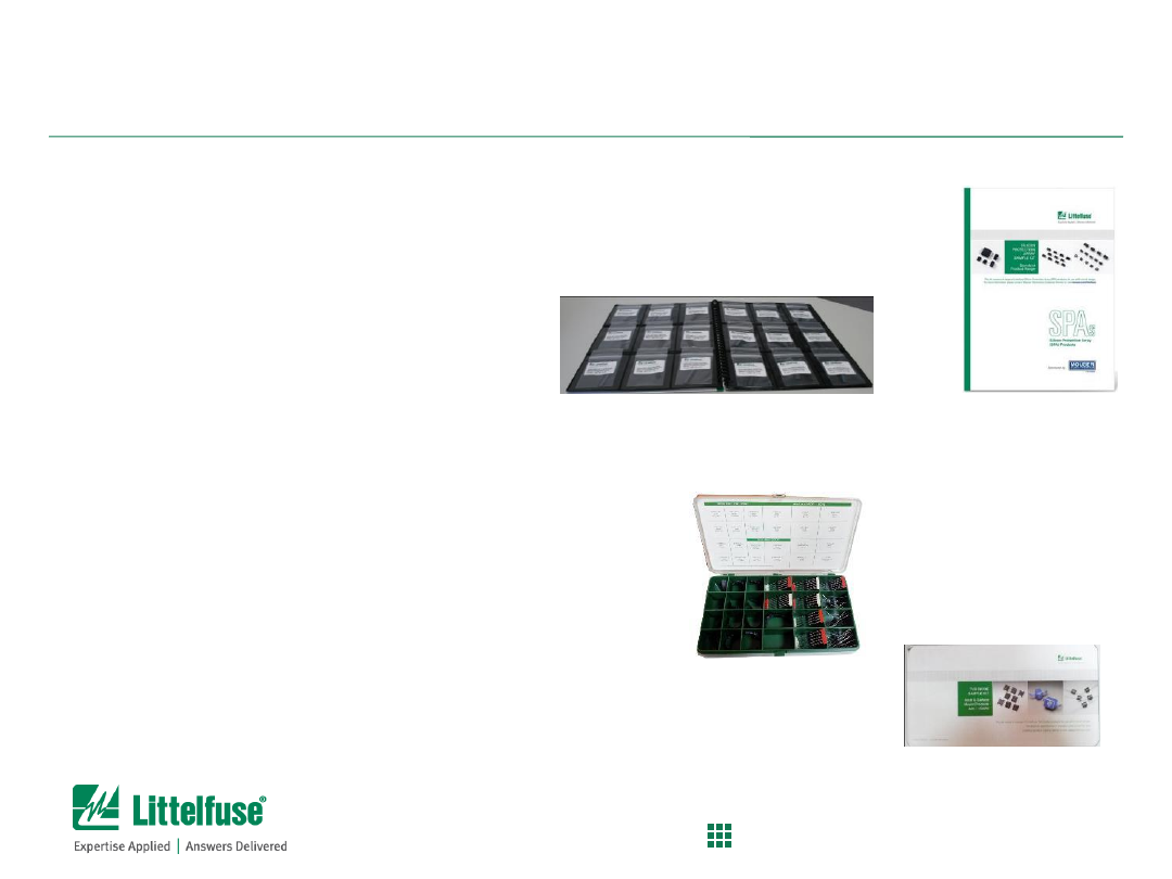
Additional Literature
Sample Kits
TVS Diode Arrays
Contains over 55 products and includes all 2012 new product releases
TVS Diodes
Axial Lead 400-1500W
SA5.0A, SA12CA, SAC5.0, P6KE27CA, P6KE200A,
1.5KE91A, 1.5KE440A, LEC28A
Surface Mount 400-1500W
SMAJ5.0A, SMAJ58A, P4SMA20CA, P4SMA200CA,
SMBJ15A, SMBJ33CA, P6SMB36A, P6SMB200CA,
1KSMB47CA, 1KSMB160A, SMCJ24CA, SMCJ64A,
1.5SMC6.8A, 1.5SMC550CA
55
Confidential and Proprietary to Littelfuse. Littelfuse, Inc. © 2014
PROTECT
|
CONTROL
|
SENSE
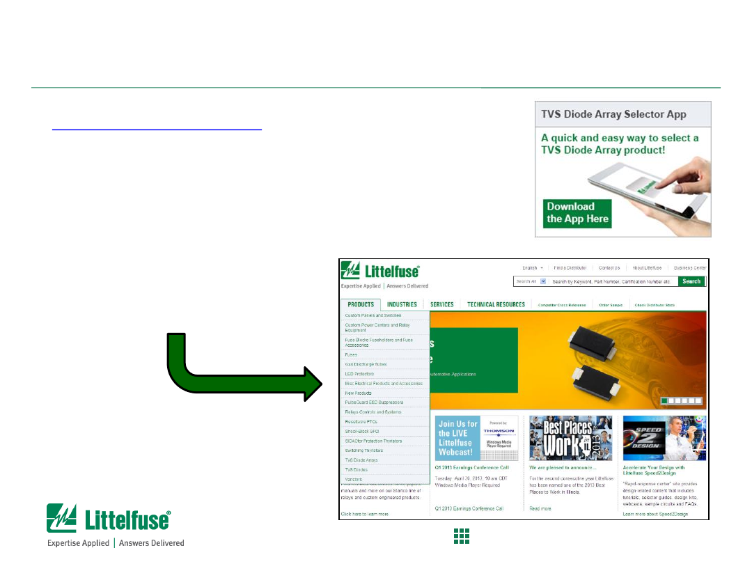
Additional Literature
Miscellaneous
Only for the iPhone/iPad
Help in finding the right product for your application
Product Catalogs
Found on Littelfuse.com
Catalogs are available under the
respective product category

56
Confidential and Proprietary to Littelfuse. Littelfuse, Inc. © 2014
PROTECT
|
CONTROL
|
SENSE
About Littelfuse
57
Confidential and Proprietary to Littelfuse. Littelfuse, Inc. © 2014
PROTECT
|
CONTROL
|
SENSE
Who is Littelfuse?
Founded 1927 in Chicago, Ill., USA
Traded on the U.S. NASDAQ; Symbol: LFUS
6,300 employees
35 facilities worldwide:
– Americas
– Europe
– Asia

58
Confidential and Proprietary to Littelfuse. Littelfuse, Inc. © 2014
PROTECT
|
CONTROL
|
SENSE
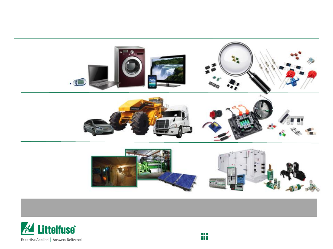
Littelfuse Products
Global Presence
– Local Resources
Electronics
600,000 sq. ft.
Automotive
and Electrical
375,000 sq. ft.
Electrical
70,000 sq. ft.
Automotive
70,000 sq. ft.
Founded in 1927
World Headquarters in Chicago, IL
More than 5,000 employees
Publicly held company since 1992
– NASDAQ
7
“
world class
”
manufacturing sites
*Yahoo Finance
59
Confidential and Proprietary to Littelfuse. Littelfuse, Inc. © 2014
PROTECT
|
CONTROL
|
SENSE
The #1 Brand in Circuit Protection
— Emerging
Player in Power Control and Sensing
Electrical
(16%)
Power Fuse
Relay/Custom
Littelfuse has the broadest and deepest portfolio of circuit protection products serving three major
market segments.
Automotive
(35%)
Auto Fuse
Commercial Vehicle
Sensors
Electronics
(49%)
Passives
Semis
Sensors
60
Confidential and Proprietary to Littelfuse. Littelfuse, Inc. © 2014
PROTECT
|
CONTROL
|
SENSE
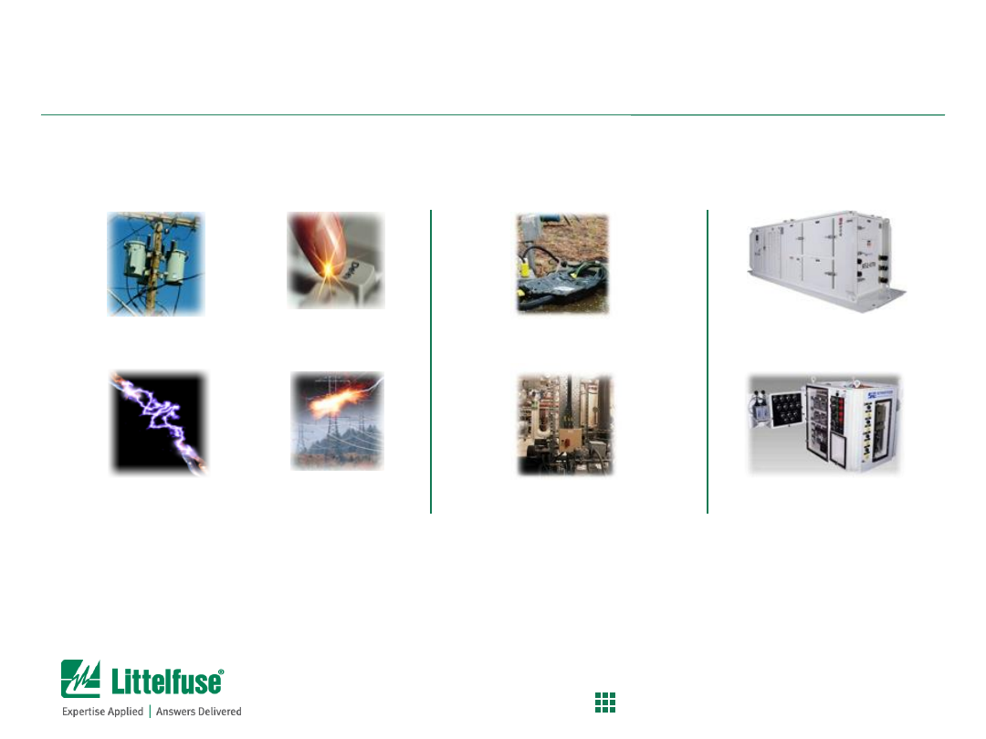
Littelfuse Protects Against Common Threats
to Electrical Circuits and Components
Overcurrent
Protection
Overvoltage
Protection
Power Monitoring and
Protective Switching
Power Cross
Overloads &
Short Circuits
ESD Protection
Lightning
Protection
Equipment
Protection
Ground-Fault Protection
Power Distribution
and Control
Mining Control
Consoles
Power Distribution Centers
Every product that uses electrical energy needs circuit protection
to ensure safety, reliability and performance.