Ultra High Precision Bulk Metal
®
Foil Technology
4 Resistor Surface Mount Hermetic Network with
0.5 ppm/°C TCR Tracking and 0.005 % Tolerance Match
SMNH
Vishay Foil Resistors
Document Number: 63092
For any questions, contact:
foil@vishaypg.com
www.foilresistors.com
Revision: 25-Mar-10
1
INTRODUCTION
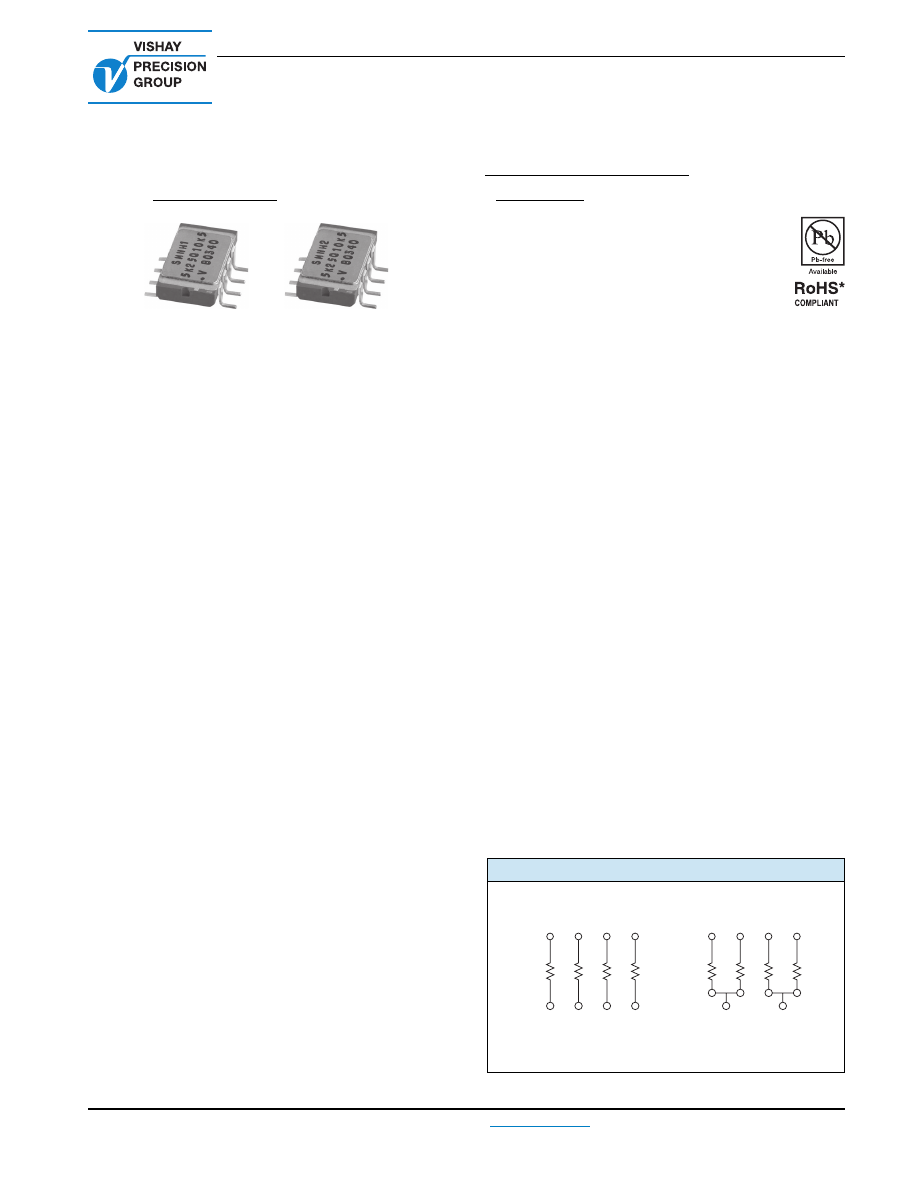
Vishay model SMNH networks incorporate all the
performance features of Vishay Bulk Metal
®
Foil technology
in a product ready for surface mounting. The 8 pin gull wing
side brazed DIP is the smallest ceramic package. Ceramic
has the advantage of electrical isolation on the underside
and high heat dissipation capability.
Resistors in network form, around the operational amplifier
for example, are called upon to track at changing ambient
temperature, to hold ratio under power and to force the ratio
changes over a period of time to be very low.
The hermeticity, the location of the chips within the package
and the “heat-sink effect” of the ceramic package itself help
preserve uniform conditions inside it. The Bulk Metal Foil
Vishay technology advantage in such a construction assures
remarkable performance due to the following factors:
- fundamentally low TCR
- very small drift with load over time
- common behavior: all drifts move in the same direction
with temperature, load and time
- TCR and tolerance match
- excellent tracking
The major highlights are emphasized by an excellent load life
and shelf life ratio stability.
Vishay hermetic resistor networks are based on fabrication
from a standing inventory of packages and resistor chips.
This permits quick delivery of prototypes since there are no
masks to design or trial processings to be made. Further, it
allows any combination of values, tolerances and circuits.
There are normally no engineering or setup charges, and no
minimum quantities are required. Delivery can be in two
weeks. (See network express prototype service.)
The sequence of fabrication includes selection of chips, die
attachment, wirebonding, value trimming, and hermetic
sealing. The finished product provides the stability
associated with Foil resistors in a hermetically sealed
package.
Hermetic sealing of Vishay’s networks enhances their
already inherently stable environmental performance. The
result is improved load life stability and better performance
during high temperature and moisture exposure.
FEATURES
•
Temperature coefficient of resistance (TCR):
absolute: ± 2 ppm/°C typical
(- 55 °C to + 125 °C, + 25 °C ref.)
tracking: ± 0.5 ppm/°C typical
•
Resistance range: 5
Ω
to 33 k
Ω
•
Vishay Foil resistors are not restricted to standard values;
specific “as required” values can be supplied at no extra
cost or delivery (e.g. 1K2345 vs. 1K)
•
Power rating: at 70 °C
Entire package: 0.4 W
Each resistor: 0.1 W
•
Resistance tolerance match: ± 0.005 %
•
Load life stability per resistor: 0.005 % (0.1 W at 70 °C,
1000 h)
•
Load life stability ratio: 0.005 % (0.1 W at 70 °C)
•
Shelf life stability per resistor: 0.0002 % (2 ppm)
•
Shelf life stability ratio: 0.0001 % (1 ppm)
•
Electrostatic discharge (ESD) up to 25 000 V
•
Short time overload
≤
0.002 % (20 ppm)
•
Non-inductive, non-capacitive design
•
Rise time: 1 ns effectively no ringing
•
Thermal stabilization time < 1 s (nominal value achieved
within 10 ppm of steady state value)
•
Current noise: 0.010 µV
RMS
/V of applied voltage (< - 40 dB)
•
Voltage coefficient: < 0.1 ppm/V
•
Non inductive: < 0.08 µH
•
Non hot spot design
•
Terminal finish: gold plated (lead (Pb)-free)
•
For better performances please contact us
•
Available with Z-Foil technology for improved TCR to
0.2 ppm/°C
•
Compliant to RoHS directive 2002/95/EC
* Pb containing terminations are not RoHS compliant, exemptions may apply
FIGURE 1 - SCHEMATICS
Note:
R
1
and R
2
may
b
e same
v
al
u
e, if desired
SMNH1
R
1
1
8
R
2
3
6
R
2
2
7
R
1
4
5
SMNH2
R
1
8
R
2
3
6
R
2
2
7
R
1
5
smnh-html.html
SMNH
Vishay Foil Resistors
www.foilresistors.com
For any questions, contact:
foil@vishaypg.com
Document Number: 63092
2
Revision: 25-Mar-10
Note
(1)
Each resistor element 0.1 W at + 70 °C (0.4 W per package)
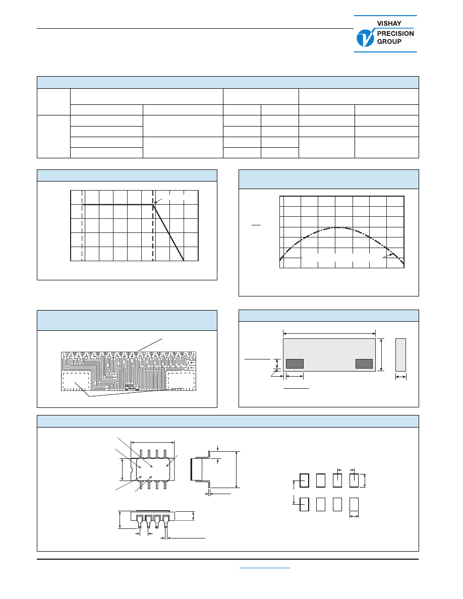
TABLE 1 - MODEL SMNH SPECIFICATIONS
MODEL
ABSOLUTE TCR
(- 55 °C to + 125 °C, + 25 °C ref.)
TOLERANCE
TCR TRACKING (max.)
RESISTANCE VALUES
TYPICAL + MAX. SPREAD ABSOLUTE
MATCH
SAME VALUES
DIFFERENT VALUES
SMNH
500
Ω
to 33 k
Ω
± 2 ± 2.5 ppm/°C
±
0.005 %
0.005 %
0.5 ppm/°C
1 ppm/°C
100
Ω
to 500
Ω
± 0.01 %
0.005 %
2 ppm/°C
3 ppm/°C
10
Ω
to 100
Ω
± 2 ± 3.5 ppm/°C
± 0.02 %
0.01 %
4 ppm/°C
5 ppm/°C
5
Ω
to 10
Ω
± 0.05 %
0.02 %
FIGURE 2 - POWER DERATING CURVE
(1)
FIGURE 4 - FORMAT OF CHIP RESISTOR
USED IN HERMETIC NETWORKS
125
100
75
50
25
0
- 75
Ambient Temperature (°C)
Percent of Rated Power
- 55 °C
+ 70 °C
Rated Power
150
125
100
75
50
25
0
- 25
- 50
Trim Points
Gold Plated Pads
V15X5
FIGURE 3 - TYPICAL RESISTANCE/
TEMPERATURE CURVE
FIGURE 5 - DIMENSIONS
in inches (millimeters)
(For more details, see ta
b
le 1)
- 55
± 2 ppm/°C (+ 25 °C Reference)
+ 150
+ 100
+ 50
0
- 50
- 100
- 150
- 200
Δ
R
R
(ppm)
- 50
- 25
0
+ 25
+ 50
+ 100 + 125
+ 75
Ambient Temperature (°C)
V15X5
0.150 ± 0.005
(3.81 ± 0.127)
0.005 ± 0.004
(1.27 ± 0.102)
0.050 ± 0.005
(1.27 ± 0.127)
+ 0.001
- 0.004
0.029
+ 0.025
- 0.102
(0.737 )
+ 0.001
- 0.004
0.019
+ 0.025
- 0.102
(0.483 )
0.020 ± 0.005
(0.508 ± 0.127)
FIGURE 6 - DIMENSIONS AND IMPRINTING EXAMPLE
in inches (millimeters)
0.38
0.024
0.138
0.1
Proposed Land Pattern
SMNH1
10K5Q5K25
.V B0320
0.520 ± 0.020
(13.21 ± 0.51)
0.090 Max.
(2.29)
0.4
70 Max.
(11.94)
0.008 ± 0.016
(0.20 ± 0.41)
Date Code
Value R
2
Pin 1 Identification
Value R
1
Ratio Tolerance Code
0.295 ± 0.010
(7.49 ± 0.25)
0.100 Max.
(2.54)
0.180 Max.
(4.57)
0.100 Typ.
(2.54)
0.015 to 0.022
(0.38 to 0.56)
smnh-html.html
SMNH
Vishay Foil Resistors
Document Number: 63092
For any questions, contact:
foil@vishaypg.com
www.foilresistors.com
Revision: 25-Mar-10
3
Notes
•
Δ
R’s are not cumulative. For purposes of determining reliability calculations, consider the characteristics shown as figures of merit and allow
no more than ± 0.05
Δ
R lifetime. Allow proportionately less if the severity of anticipated environmental stresses are small compared to the
tests as defined in MIL-PRF-83401.
• Post manufacturing operation (PMO) has the effect of minimizing
Δ
R’s. Consult Vishay applications engineering for details.
•
Δ
Ratio refers to the change in ratio between resistors within the network package from before, to after, the specified test.
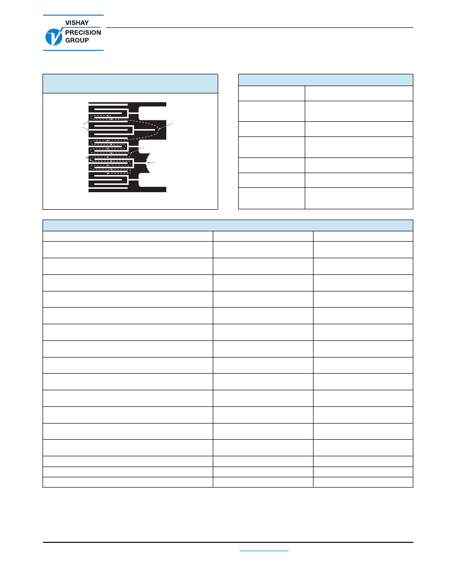
FIGURE 7 - TRIMMING TO VALUES
(Conceptual Illustration)
Note:
Foil sho
w
n in
b
lack, etched spaces in
w
hite
Mutual
Inductance
Reduction due
to Opposin
g
Current in
Adjacent Lines
Current Path
Before Trimmin
g
Interloop
Capacitance
Reduction
in Series
Trimmin
g
Process
Removes this Material
from Shortin
g
Strip Area
Chan
g
in
g
Current Path
and Increasin
g
Resistance
Current Path
After Trimmin
g
TABLE 2 - MECHANICAL SPECIFICATIONS
Resistive Element
High precision Bulk Metal Foil chips
Body
Ceramic package:
94 % alumina (Al
2
O
3
)
Lid
Gold plated kovar
Terminals
Alloy 42 (iron nickel) with 100 µ" gold
plating (MIL-STD-1276, type G-21-A)
Internal Connections
Gold wire bonding
Solderability
Per MIL-PRF-83401
Marking Resistance
to Solvents
Permanency testing per
MIL-PRF-83401
TABLE 3 - PERFORMANCE SPECIFICATIONS (PER MIL-PRF 83401 TEST METHODS)
SPECIFICATIONS
TYPICAL LIMITS
MAXIMUM LIMITS
Thermal Shock
5 x (- 65 °C to + 125 °C) and
Power Conditioning
1.5 rated power at 25 °C, 100 h
Δ
R = 0.003 % (30 ppm)
Δ
Ratio = 0.001 % (10 ppm)
0.015 % (150 ppm)
0.015 % (150 ppm)
Low Temperature Operation
Δ
R = 0.005 % (50 ppm)
Δ
Ratio = 0.005 % (50 ppm)
0.01 % (100 ppm)
0.01 % (100 ppm)
Short Time Overload
6.25 rated power; 5 s
Δ
R = 0.002 % (20 ppm)
Δ
Ratio = 0.002 % (20 ppm)
0.01 % (100 ppm)
0.01 % (100 ppm)
Terminal Strength
Δ
R = 0.001 % (10 ppm)
Δ
Ratio = 0.001 % (10 ppm)
0.01 % (100 ppm)
0.01 % (100 ppm)
Resistance to Soldering Heat
260 °C, 10 s
Δ
R = 0.002 % (20 ppm)
Δ
Ratio = 0.001 % (10 ppm)
0.01 % (100 ppm)
0.01 % (100 ppm)
Moisture Resistance
Δ
R = 0.003 % (30 ppm)
Δ
Ratio = 0.003 % (30 ppm)
0.01 % (100 ppm)
0.01 % (100 ppm)
Shock
100 G, sawtooth
Δ
R = 0.001 % (10 ppm)
Δ
Ratio = 0.001 % (10 ppm)
0.01 % (100 ppm)
0.01 % (100 ppm)
Vibration, High Frequency
Δ
R = 0.001 % (10 ppm)
Δ
Ratio = 0.001 % (10 ppm)
0.01 % (100 ppm)
0.01 % (100 ppm)
Load Life
1000 h at + 70 °C; 0.1 W per resistor
Δ
R = 0.005 % (50 ppm)
Δ
Ratio = 0.005 % (50 ppm)
0.025 % (250 ppm)
0.01 % (100 ppm)
Load Life
1000 h at + 25 °C; 0.1 W per resistor
Δ
R = 0.002 % (20 ppm)
Δ
Ratio = 0.001 % (10 ppm)
0.01 % (100 ppm)
0.01 % (100 ppm)
High Temperature Exposure
100 h at + 125 °C
Δ
R = 0.005 % (50 ppm)
Δ
Ratio = 0.005 % (50 ppm)
0.01 % (100 ppm)
0.01 % (100 ppm)
Low Temperature Storage
24 h at - 65 °C
Δ
R = 0.002 % (20 ppm)
Δ
Ratio = 0.002 % (20 ppm)
0.01 % (100 ppm)
0.01 % (100 ppm)
Shelf Life Stability
(6 years)
Δ
R = 0.0002 % (2 ppm)
Δ
Ratio = 0.0001 % (1 ppm)
Insulation Resistance
100 V (DC)
> 10
4
M
Ω
DWV Atm. Pressure
200 V
Weight
0.95 g
smnh-html.html

SMNH
Vishay Foil Resistors
www.foilresistors.com
For any questions, contact:
foil@vishaypg.com
Document Number: 63092
4
Revision: 25-Mar-10
QUALITY INSPECTION AND TESTING
Network performance is established during the engineering design phase and is dependent on the materials of construction. Most
characteristics are inherent in the Bulk Metal
Foil technology and provide the high order of performance displayed throughout this
catalog. Stability and drift levels can be improved beyond those shown in the catalog. Applications engineering is available to
recommend screen testing beyond the standard outgoing inspection when catalog limits are insufficient. The chart below shows
the standard outgoing testing and the additional user specified screen tests that may be appropriate for a particular application.
TESTING OF COMMERCIAL PRODUCT - VISHAY NETWORKS
Our standard outgoing testing consists of:
1. DC resistance test 100 %
1. 1 Conformity to value
1. 2 Conformity to tolerance
2. Visual and Mechanical 100 %
2. 1 Conformity to physical size
2. 2 Cleanliness of leads
2. 3 Conformity of printing
3. Ship check (sample plan)
3. 1 Conformity of packaging
3. 2 Conformity of count
ADDITIONAL TESTING TO MIL SPEC
Group A testing to MIL-PRF-83401 imposes the following:
1. Thermal shock 100 %
5X from - 65 °C to + 125 °C
2. Power conditioning 100 %
2. 1 100 h at 25 °C, 1.5 x rated power
2. 2
Δ
R and
Δ
Ratio calculation
3. Visual and mechanical after the above tests (sample plan)
3. 1 Conformity to physical size
3. 2 Workmanship
3. 3 Damage due to the above tests
4. 10 % PDA or one piece whichever is greater
5. Solderability (sample plan)
Group B sample testing to MIL-PRF-83401 imposes the following:
1. Temperature coefficient of resistance (sample plan)
2. Resistance to solvents (sample plan)
smnh-html.html
SMNH
Vishay Foil Resistors
Document Number: 63092
For any questions, contact:
foil@vishaypg.com
www.foilresistors.com
Revision: 25-Mar-10
5
Note
(1)
Application engineering release: for non-standard requests, please contact application engineering
Note
• Other values available upon request
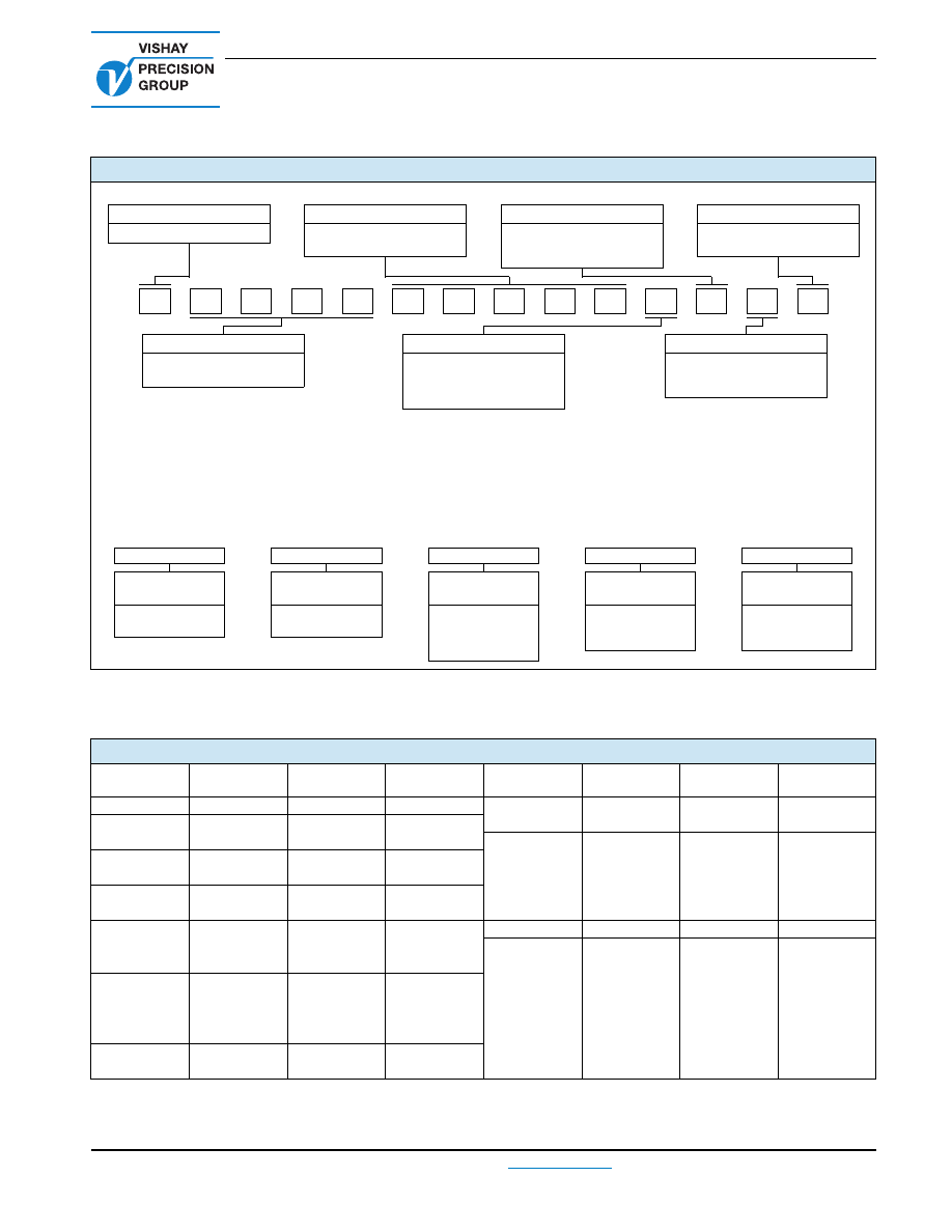
TABLE 4 - GLOBAL PART NUMBER INFORMATION
(1)
NEW GLOBAL PART NUMBER: Y1521V0207TV0L (preferred part number format)
DENOTES PRECISION
VCODE
TOLERANCE MATCH
PACKAGING
Y
RESISTANCE
VALUE CODE
V
= 0.005 %
T
= 0.01 %
Q
= 0.02 %
L
= bulk pack
U
= ESD tubes
PRODUCT CODE
ABSOLUTE TOLERANCE
CHARACTERISTICS
SMNH1
= 1521
SMNH2
= 1522
V
= ± 0.005 %
T
= ± 0.01 %
Q
= ± 0.02 %
A
= ± 0.05 %
0
= gold plated termination
(lead (Pb)-free)
1 to 99
8
= custom
FOR EXAMPLE: ABOVE GLOBAL ORDER Y1521 V0207 T V 0 L:
TYPE: SMNH1
VALUES: 10K/5K (see VCODE V0207 in table 5 below)
ABSOLUTE TOLERANCE: ± 0.01 %
TOLERANCE MATCH: 0.005 %
TERMINATION: gold plated (lead (Pb)-free)
PACKAGING: bulk pack
HISTORICAL PART NUMBER: SMNH1 10K/5K T V B (will continue to be used)
SMNH1
10K/5K
T
V
B
MODEL
RESISTANCE
VALUE
TOLERANCE
TOLERANCE
MATCH
PACKAGING
SMNH1
SMNH2
R
1
= 10 k
Ω
R
2
= 5 k
Ω
V
= ± 0.005 %
T
= ± 0.01 %
Q
= ± 0.02 %
A
= ± 0.05 %
V
= 0.005 %
T
= 0.01 %
Q
= 0.02 %
B
= bulk pack
(ESD plastic box)
U
= ESD tubes
TABLE 5 - RESISTANCE VALUE CODE LIST FOR POPULAR RATIOS
VCODES
R
1
/R
2
RATIO
R
1
R
2
VCODES
R
1
/R
2
RATIO
R
1
R
2
V0201
100
10K
100R
V0189
2.5
1K
400R
V0202
50
10K
200R
V0185
500R
200R
V0197
5K
100R
V0207
2
10K
5K
V0203
25
10K
400R
V0175
2K
1K
V0198
5K
200R
V0190
1K
500R
V0204
20
10K
500R
V0182
400R
200R
V0193
2K
100R
V0179
200R
100R
V0205
10
10K
1K
V0186
1.25
500R
400R
V0194
2K
200R
V0178
V0180
V0183
V0023
V0191
V0176
V0019
V0008
1
100R
200R
400R
500R
1K
2K
5K
10K
100R
200R
400R
500R
1K
2K
5K
10K
V0187
1K
100R
V0200
5
5K
1K
V0195
2K
400R
V0188
1K
200R
V0184
500R
100R
V0196
4
2K
500R
V0181
400R
100R
5
2
1
V
2
0
7
0
Y
1
V
0
T
L
smnh-html.html

Vishay Precision Group
Document No.: 63999
Revision: 27-Apr-2011
www.vishaypg.com
1
Legal Disclaimer Notice
Disclaimer
Legal Disclaimer Notice
Disclaimer
Document No.: 63999
Revision: 27-Apr-2011
ALL PRODUCTS, PRODUCT SPECIFICATIONS AND DATA ARE SUBJECT TO CHANGE WITHOUT NOTICE.
Vishay Precision Group, Inc., its affiliates, agents, and employees, and all persons acting on its or their
behalf (collectively, “Vishay Precision Group”), disclaim any and all liability for any errors, inaccuracies or
incompleteness contained herein or in any other disclosure relating to any product.
The product specifications do not expand or otherwise modify Vishay Precision Group’s terms and
conditions of purchase, including but not limited to, the warranty expressed therein.
Vishay Precision Group makes no warranty, representation or guarantee other than as set forth in the terms
and conditions of purchase.
To the maximum extent permitted by applicable law, Vishay Precision
Group disclaims (i) any and all liability arising out of the application or use of any product, (ii) any and
all liability, including without limitation special, consequential or incidental damages, and (iii) any and
all implied warranties, including warranties of fitness for particular purpose, non-infringement and
merchantability.
Information provided in datasheets and/or specifications may vary from actual results in different
applications and performance may vary over time. Statements regarding the suitability of products for
certain types of applications are based on Vishay Precision Group’s knowledge of typical requirements that
are often placed on Vishay Precision Group products. It is the customer’s responsibility to validate that a
particular product with the properties described in the product specification is suitable for use in a particular
application.
No license, express, implied, or otherwise, to any intellectual property rights is granted by this document, or
by any conduct of Vishay Precision Group.
The products shown herein are not designed for use in life-saving or life-sustaining applications unless
otherwise expressly indicated. Customers using or selling Vishay Precision Group products not expressly
indicated for use in such applications do so entirely at their own risk and agree to fully indemnify Vishay
Precision Group for any damages arising or resulting from such use or sale. Please contact authorized
Vishay Precision Group personnel to obtain written terms and conditions regarding products designed for
such applications.
Product names and markings noted herein may be trademarks of their respective owners.