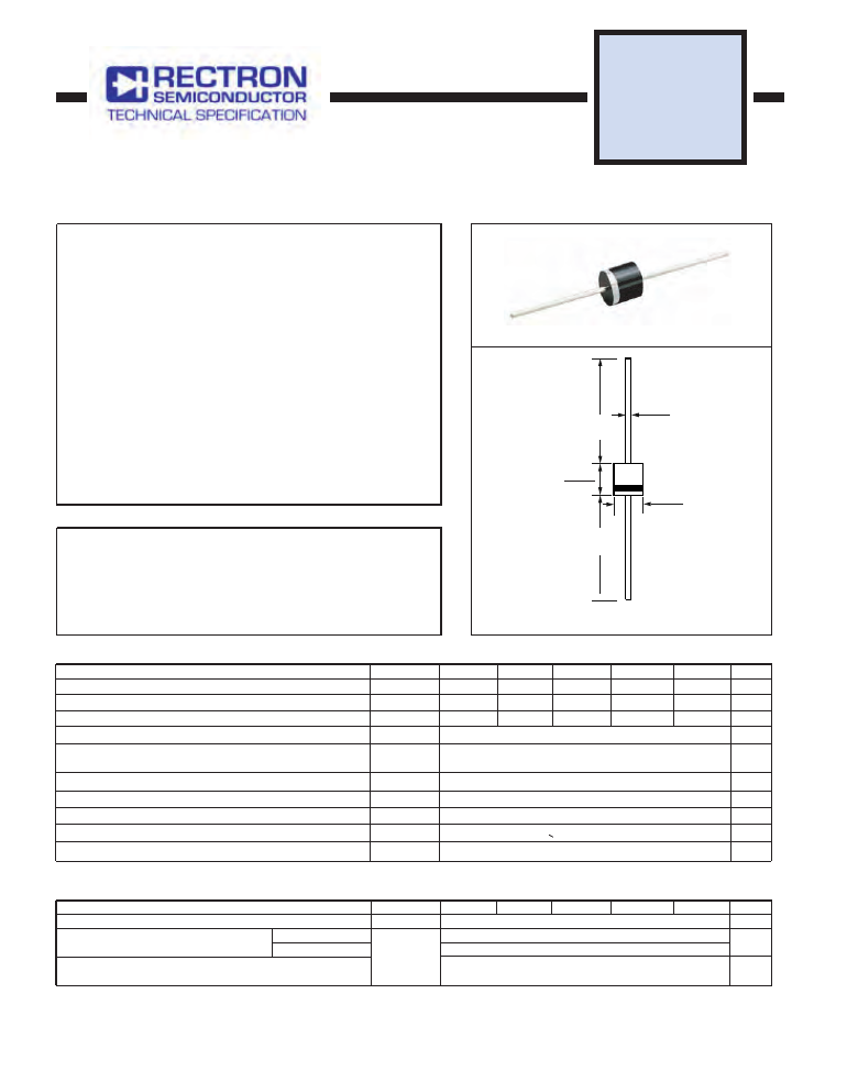
SILICON RECTIFIER
VOLAGE RANGE 50 to 600 Volts CURRENT 15 Ampere
FEATURES
* Low cost
* Low leakage
* Low forward voltage drop
* High current capability
* High surge current capability
MECHANICAL DATA
*
Case: Molded plastic
*
Epoxy: Device has UL flammability classification 94V-O
*
Lead: MIL-STD-202E method 208C guaranteed
*
Mounting position: Any
*
Weight: 2.08 grams
MAXIMUM RATINGS AND ELECTRICAL CHARACTERISTICS
Ratings at 25
o
C ambient temperature unless otherwise specified.
resistive or inductive load.
SPA1501
R-7
MA XIMUM R AT ING S
(At T
A
= 25
o
C unless otherwise noted)
ELECTRICAL CHARACTERISTICS
(At T
A
= 25
o
C unless otherwise noted)
NOTES : 1. Measured at 1 MH
2. Heat-sink mounted 10mm max from body
Z
and applied reverse voltage of 4.0 volts
Dimensions in inches and (millimeters)
2009-10
REV:O
RATINGS
Maximum Recurrent Peak Reverse Voltage
Maximum RMS Voltage
Maximum DC Blocking Voltage
Peak Forward Surge Current 8.3 ms single half sine-wave
superimposed on rated load (JEDEC method)
Typical Junction Capacitance (Note)
Typical Current Squared Time
Typical Thermal Resistance
SYMBOL
V
RRM
V
DC
I
FSM
C
J
T
J
T
STG
V
RMS
UNITS
Volts
Volts
Volts
Amps
15
400
663.7
125
7
Amps
A
2
S
pF
0
C
0
C
200
140
200
100
70
100
400
280
400
600
480
600
Storage T
Operating Temperature Range
emperature Range
R
θ
J A
I
O
-55 to +175
0
C/ W
at Rated DC Blocking Voltage
CHARACTERISTICS
Maximum Full Load Reverse Current Average Full Cycle
.375” (9.5mm) lead length at T
L
= 75
o
C
V
F
SYMBOL
I
R
UNITS
1.0
uAmps
uAmps
Maximum DC Reverse Current
Maximum Instantaneous Forward Voltage at 15A DC
Volts
@T
A
= 25
o
C
@T
A
= 100
o
C
10
100
50
I
2
T
SPA1501
SPA1502
SPA1503
SPA1504
SPA1505
SPA1501
SPA1502
SPA1503
SPA1504
SPA1505
50
50
35
THRU
SPA1505
* Ideal for solar panel PV application such as By-Pass diode
175(Tj<200
o
C in Bypass Mode)
@T
L
=125
o
C(Note 2)
Maximum DC Forward Current
.299(7.6)
.291(7.4)
.96 (24.5)
MIN.
.96 (24.5)
MIN.
DIA.
.065 (1.65)
.061 (1.55)
.319(8.1)
.311(7.9)
DIA.
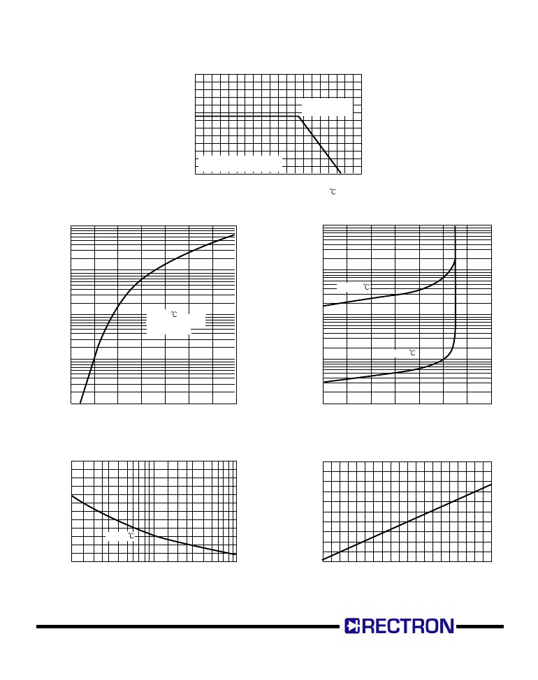
RATING AND CHARACTERISTIC CURVES ( SPA1501 THRU SPA1505 )
FIG. 1 - TYPICAL FORWARD CURRENT DERATING CURVE
A
V
E
R
A
G
E
F
O
R
W
A
R
D
C
U
R
R
E
N
T,
(A
)
AMBIENT TEMPERATURE, ( )
10
14
6
2
0
0
20 40 60 80 100 120 140 160 180 200
FIG. 2 - TYPICAL INSTANTANEOUS FORWARD
CHARACTERISTICS
IN
S
TA
N
TA
N
E
O
U
S
F
O
R
W
A
R
D
C
U
R
R
E
N
T,
(A
)
INSTANTANEOUS FORWARD VOLTAGE, (V)
TJ = 25
Pulse Width=300uS
1% Duty Cycle
1000
100
10
1.0
.1
.6
.8
1.0
1.2
1.4
1.6
1.8
2.0
FIG. 3 - MAXIMUM NON-REPETITIVE FORWARD
P
E
A
K
F
O
R
W
A
R
D
S
U
R
G
E
C
U
R
R
E
N
T,
(A
)
NUMBER OF CYCLES AT 60Hz
SURGE CURRENT
TJ = 25
600
500
400
300
200
100
0
1
2
5
10
20
50
100
FIG. 3 - TYPICAL REVERSE CHARACTERISTICS
IN
S
TA
N
TA
N
E
O
U
S
R
E
V
E
R
S
E
C
U
R
R
E
N
T,
(u
A
)
PERCENT OF RATED PEAK REVERSE VOLTAGE, (%)
0
20
40
60
80
100 120
140
100
10
1.0
.1
.01
TJ = 100
TJ = 25
FIG. 5 - TYPICAL THERMAL RESISTANCE VS
LEAD LENGTH
TH
E
R
M
A
L
R
E
S
IS
TA
N
C
E
(
¢J
/W
)
EQUAL LEAD LENGTH TO HEAT SINK, (IN.)
0 .1
.2 .3
.4
.5
.6
.7
.8 .9 1.0
20
15
10
5
0
25
20
26
Single Phase Half Wave 60Hz
Resistive or Inductive Load
D.C with heat sink
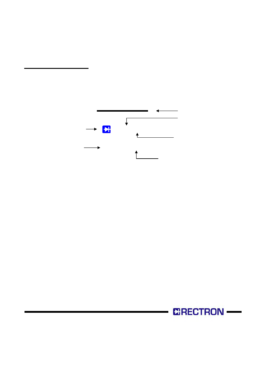
Marking Description
V Y M
1 5 A X
Cathode Band
Rectron Logo
Year – code:
(Y:Last digit of year)
Month – code:
(M:0~9,O,N,D)
Part No.
Voltage-code
01-------50V 04------400V
02-------100V 05------600V
03--------200V

Rectron Inc reserves the right to make changes without notice to any product
specification herein, to make corrections, modifications, enhancements or other
changes. Rectron Inc or anyone on its behalf assumes no responsibility or liabi-
lity for any errors or inaccuracies. Data sheet specifications and its information
contained are intended to provide a product description only. "Typical" paramet-
ers which may be included on RECTRON data sheets and/ or specifications ca-
n and do vary in different applications and actual performance may vary over ti-
me. Rectron Inc does not assume any liability arising out of the application or
use of any product or circuit.
Rectron products are not designed, intended or authorized for use in medical,
life-saving implant or other applications intended for life-sustaining or other rela-
ted applications where a failure or malfunction of component or circuitry may di-
rectly or indirectly cause injury or threaten a life without expressed written appr-
oval of Rectron Inc. Customers using or selling Rectron components for use in
such applications do so at their own risk and shall agree to fully indemnify Rect-
ron Inc and its subsidiaries harmless against all claims, damages and expendit-
ures.
DISCLAIMER NOTICE