1
J. CLASSES OF DIELECTRICS
Dielectric formulations are identified and classified in the industry by the capacitance temperature
coefficient of materials. Two basic groups (Class I and Class II) are used in the manufacture of
ceramic chip capacitors. A third (Class III) identifies the reduced barium titanate barrier-layer
formulations utilized in the production of disc capacitors.
The temperature coefficients are determined by measurement of the capacitance change at various
temperatures from reference room temperature (25°C), using an environmental chamber. The tem-
perature coefficient (T.C.) is expressed as the percent capacitance change (%
∆
C) or parts per mil-
lion per degree C (ppm/°C) change from reference. The T.C. characteristic is usually illustrated
graphically over the standard EIA and MIL temperature ranges (-55
°
C to 85
°
C, and -55
°
C to 125
°
C
respectively). The method of calculation of the temperature coefficient is described in Section K-1.
C
LASS
I D
IELECTRICS
This group identifies the linear dielectrics described in Section 1. These materials display the most
stable characteristics, as they are non-ferroelectric (paraelectric) formulations, based mostly on TiO
2
,
with dielectric constants under 150. The “extended” temperature compensating ceramics are a
subgroup of formulations which utilize small additions of other (ferroelectric) oxides, such as CaTiO
3
or SrTiO
3
and which display near-linear and predictable temperature characteristics with dielectric
constants ranging up to 500. Both categories are used in circuitry requiring stability of the capaci-
tor, i.e. negligible or no aging of the dielectric constant, low loss (DF<.001, or <.002 for the ex-
tended T.C. bodies), negligible or no change in capacitance or dielectric loss with voltage or fre-
quency, and predictable linear behavior with temperature within prescribed tolerances.
A letter-number-letter code which defines the temperature coefficients of Class I dielectrics has been
developed and is defined in the Electronic Industries Association (EIA) Standard 198, as shown in
Table J-1.
The most common Class I dielectric for chip capacitors is the COG designation, i.e. 0 ppm/
°
C ±30
ppm/
°
C temperature coefficient, which is the NPO (negative-positive-zero) MIL specification, for
flat temperature coefficient.
NOVACAP
TECHNICAL BROCHURE

2
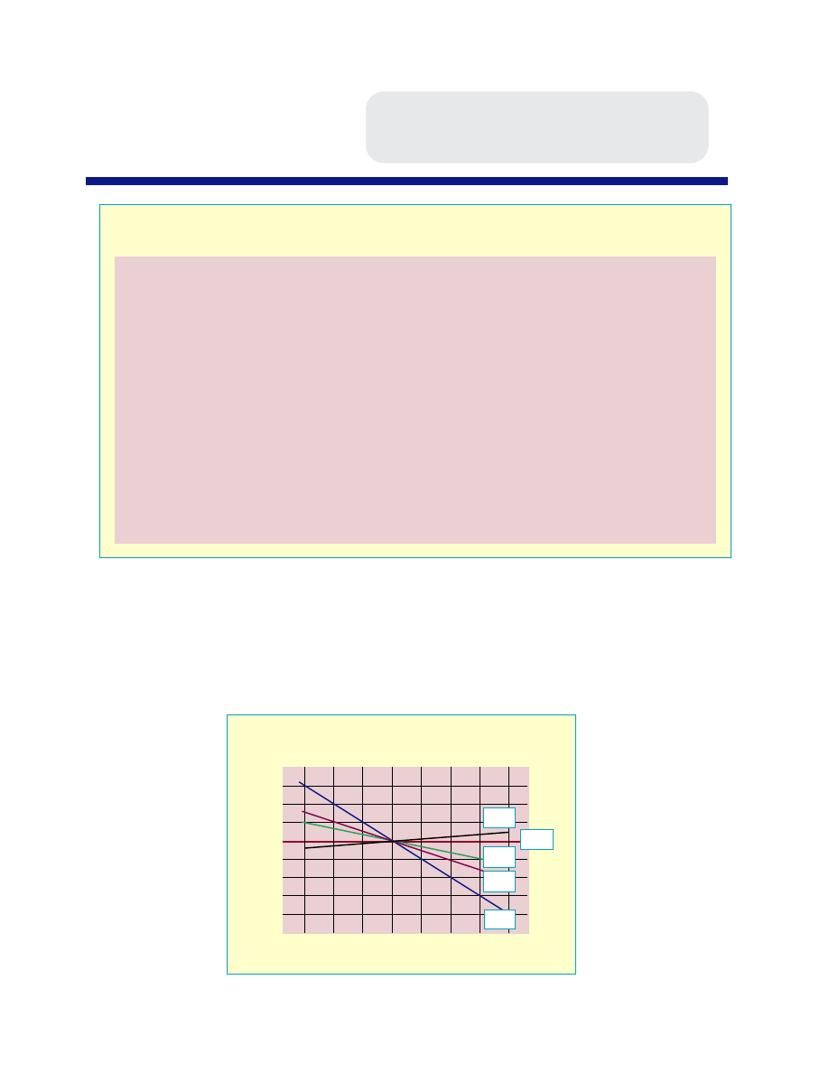
Some examples from Table J-1:
R2G
Negative
220 ppm/
°
C
±30 ppm/
°
C
(N220)
S2H
Negative
330 ppm/
°
C
±60 ppm/
°
C
(N330)
U2H Negative
750 ppm/
°
C
±60 ppm/
°
C (N750)
M7G Positive
100 ppm/
°
C
±30 ppm/
°
C
(P100)
Some of the above examples are illustrated graphically in Figure J-1.
(a)
significant figure
of temp. coeff. of
capacitance (ppm/
o
C)
0.0
1.0
1.5
2.2
3.3
4.7
7.5
(b)
letter code
for (a)
C
M
P
R
S
T
U
(c)
multiplier
applicable to
column (a)
-1.0
-10
-100
-1000
-10000
+1
+10
+100
+1000
+10000
(d)
numerical codes
for column (c)
0
1
2
3
4
5
6
7
8
9
(e)
tolerance of
temp. coeff.
(ppm/
o
C)
30
60
120
250
500
1000
2500
(f)
letter code
for column (e)
G
H
J
K
L
M
N
TABLE J - 1
EIA DESIGNATIONS FOR CLASS I DIELECTRICS
FIGURE J - 1
%
∆
C
-50 -25 0 25 50 75 100 125
temperature,
o
C
T. C. OF LINEAR DIELECTRICS
6.0
4.0
2.0
0
-2.0
-4.0
-6.0
-8.0
1234
1234
1234
M7G
1234
1234
1234
COG
1234
1234
1234
R2G
1234
1234
1234
S2H
1234
1234
1234
U2H
NOVACAP
TECHNICAL BROCHURE

3
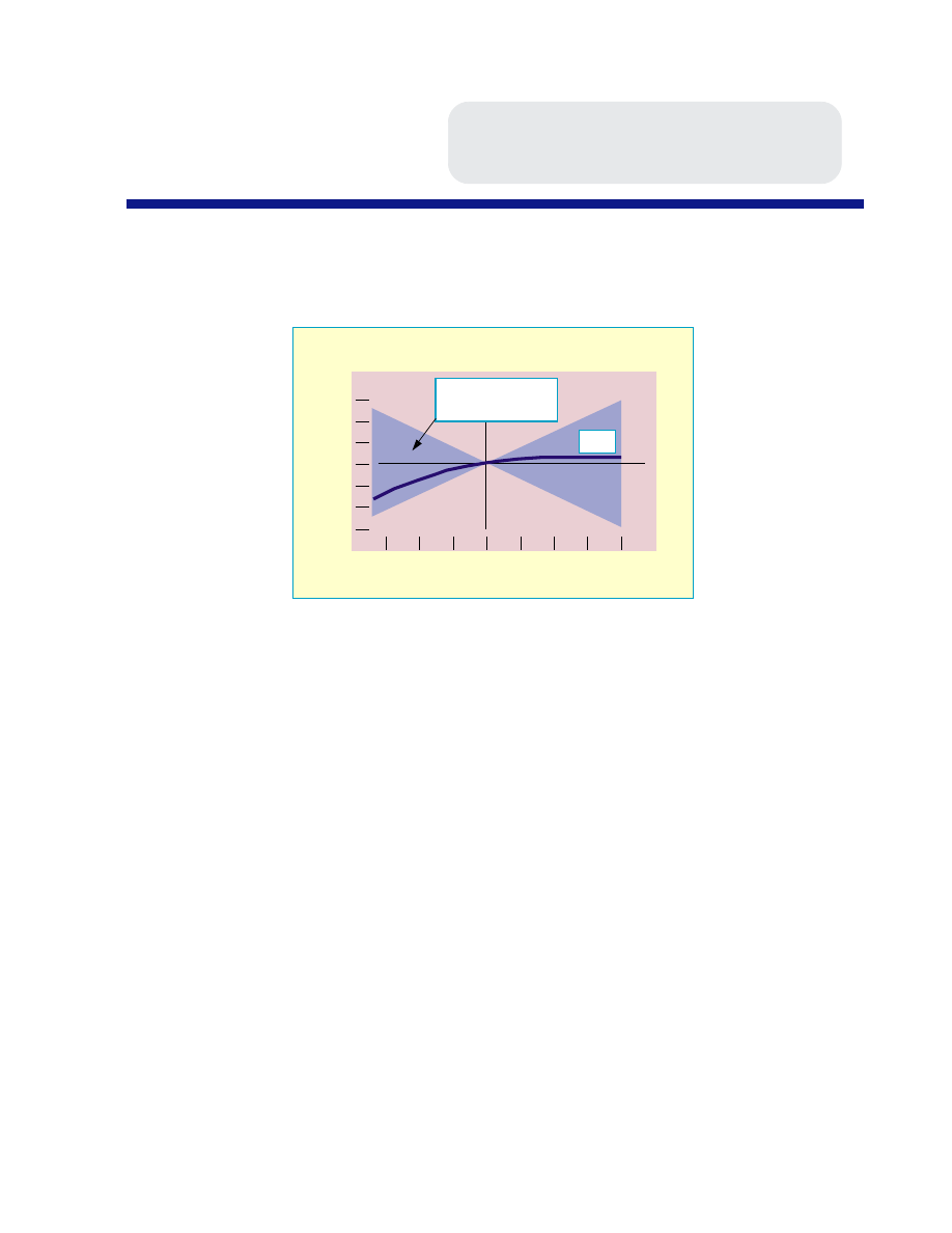
Actual measurements of temperature coefficient may not necessarily be perfectly linear, but are acceptable
if the data fall within the permissible tolerance limits specified by the last letter of the EIA code, as illus-
trated for COG dielectric in Figure J-2.
CLASS II DIELECTRICS
Class II dielectrics comprise the ferroelectric formulations described in Section H. These materials
offer much higher dielectric constants than Class I dielectrics, but with less stable properties with
temperature, voltage, frequency and time. The diverse range of properties of the ferroelectric ce-
ramics requires a subclassification into two categories, defined by the temperature characteristics:
“Stable Mid-K” Class II
, which display a maximum temperature coefficient of ±15% from
25
°
C reference over the temperature range of -55
°
C to 125
°
C. These materials typically have
dielectric constants in the range of 600 to 4000, and meet EIA X7R characteristics.
“High K” Class II
dielectrics, with temperature coefficients exceeding the X7R require-
ments. High K formulations display dielectric constants from 4000 to 18,000, with very
steep temperature coefficients, due to the fact that the Curie Point is shifted towards room
temperature for maximization of the dielectric constant.
Table J-2 shows the EIA 198 descriptions for these dielectrics. The most common Mid-K charac-
teristic used in chip capacitor manufacture is the X7R designation (±15% maximum
∆
C from -55
°
C
to 125
°
C). In the High-K category, the Z5U characteristic (+22% to -56% maximum
∆
C from
+10
°
C to +85
°
C) and Y5V (+22% to - 82% maximum
∆
C from -30
°
C to +85
°
C) are common.
The military specification for ceramic chip capacitors (MIL-C-55681) also defines the Mid-K stable
-50 -25 0 25 50 75 100 125
temperature,
o
C
%
∆
C
0.3
0.2
0.1
0
-0.1
-0.2
-0.3
FIGURE J - 2
TOLERANCE OF TEMPERATURE COEFFICIENT
1234
1234
1234
COG
+/- 30 ppm/
o
C
tolerance envelope
NOVACAP
TECHNICAL BROCHURE

4
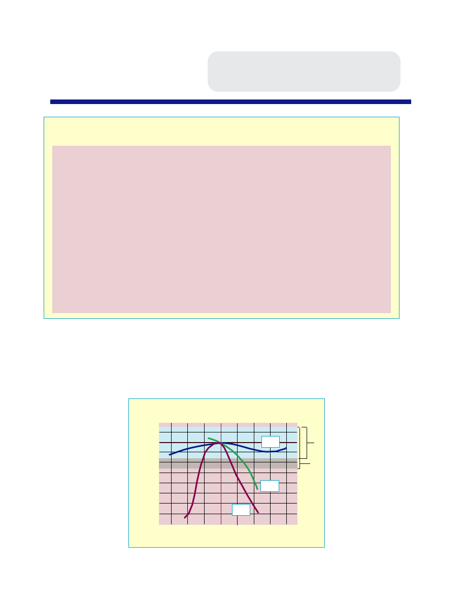
dielectric and is designated as “BX” characteristic. The BX specification has voltage temperature
limits in addition to the standard temperature limits discussed previously. BX dielectric is limited to
a ±15% maximum capacitance change from -55
°
C to 125
°
C, and to a +15% -25% maximum change
with working voltage applied. In effect, the BX characteristic is similar to the X7R designation,
with the added condition that the voltage coefficient and temperature coefficient combined do not
exceed +15% -25%
∆
C. Typical Class II T.C. curves are shown in Figure J-3.
(a)
low temperature
requirement
+10
-30
-55
(b)
letter code
for (a)
Z
Y
X
(c)
high temp.
requirement
+45
+65
+85
+105
+125
(d)
numerical codes
for column (c)
2
4
5
6
7
(e)
Max. (+/-)%
∆
C
over temp.
1.0
1.5
2.2
3.3
4.7
7.5
10.0
15.0
22.0
+22-33
+22-56
+22-82
(f)
letter code
for column (e)
A
B
C
D
E
F
P
R
S
T
U
V
TABLE J - 2
EIA DESIGNATIONS FOR CLASS II DIELECTRICS
FIGURE J - 3
%
∆
C
-50 -25 0 25 50 75 100 125
temperature,
o
C
T. C.
OF CLASS II DIELECTRICS
+10
0
-10
-20
-30
-40
-50
-60
-70
1234
1234
1234
X7R
1234
1234
Z5U
1234
1234
1234
Y5V
X7R envelope
BX TVC envelope
NOVACAP
TECHNICAL BROCHURE


