background image

TT PEAK POWER  1.0 WATT STEADY STATE

 GPP TRANSIENT VOLTAGE SUPPRESSOR

FEATURES

* Plastic package has underwriters laboratory
* Glass passivated chip construction
* 400 watt surage capability at 1ms
* Excellent clamping capability
* Low zener impedance
* Fast response time

MAXIMUM RATINGS AND ELECTRICAL CHARACTERISTICS

Ratings at 25 

o

C ambient temperature unless otherwise specified.
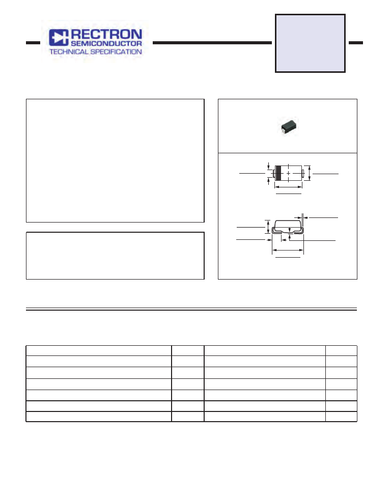
TVS

TFMAJ

SERIES

DO-214AC

400 WA

Dimensions in inches and (millimeters)

MAXIMUM RATINGS (At T

A

 = 25

o

C unless otherwise noted)

DEVICES     FOR     BIPOLAR     APPLICATIONS

For Bidirectional use C or CA suffix for types TFMAJ5.0 thru TFMAJ170

Electrical characteristics apply in both direction

2008-10

3. Lead temperature at T

= 25

o

C

NOTES :

2. Mounted on 0.2 X 0.2”( 5.0 X 5.0mm ) copper pad to each terminal.

1. Non-repetitive current pulse, per Fig.3 and derated above T

= 25

o

C per Fig.2.

4. Measured on 8.3mS single half sine-wave duty cycle = 4 pules per minute maximum.

5. Peak pulse power waveform is 10/1000uS.

RATINGS

Steady State Power Dissipation (Note 3)

Peak Pulse Current with a 10/1000uS waveform ( Note 1, Fig.2 )

Maximum Instantaneous Forward Voltage at 25A (Note 4)

SYMBOL

I

FSM

V

F

T

J

, T

STG

Volts

-55 to + 150

0

C

UNITS

Amps

Peak Power Dissipation with a 10/1000uS (Note 1,2,5 Fig.1)

Minimum 400

40

3.5

VALUE

Operating and Storage Temperature Range

P

PPM

Watts

I

PPM

Amps

SEE TABLE 1

Peak Forward Surge Current per Fig.5 (Note 3)

P

M

(

AV

)

1.0

Watts

0.012  (0.305 )

0.006  (0.152 )

0.008  (0.203 )

0.004  (0.102 )

0.209  (5.31 )
0.185  (4.70 )

0.035  (0.89 )

0.059  (1.50 )

0.067  (1.70 )

0.091  (2.31 )

0.160 (4.06 )

0.180 (4.57 )

0.086  (2.18 )

0.110  (2.79 )

0.067  (1.70 )
0.051  (1.29 )

SURFACE MOUNT GPP

tfmaj-html.html
background image

RATING AND CHARACTERISTIC CURVES ( TFMAJ5.0 THRU TFMAJ170CA )

FIG. 2 - PULSE DERATING CURVE

  P

E

A

K

 P

U

LS

E

 P

O

W

E

R

 (P

P

P

) O

R

 C

U

R

R

E

N

T

A

, AMBIENT  TEMPERATURE,(     )

 (I

P

P

) D

E

R

A

TI

N

G

 IN

 P

E

R

C

E

N

T

A

G

E

,%

Measured at
Zero Bias

Measured at
Stand off
Voltage ,VWM

f = 1.0 MHz

Vsig = 50mVp-p

TJ = 25

FIG.  4 -  TYPICAL JUNCTION CAPACITANCE

C

J

, C

A

P

A

C

IT

A

N

C

E

, p

F

V(

BR

),  BREAKDOWN VOLTACE, VOLTS

1.0

10

100

200

10000

1000

100

10

Pulse  Width (td) is Defined

as the P oint  Where the P eak

Current Deca ys to 50% of IPPM

10/1000usec.  Waveform

as Defined b y R.E.A.

Peak V alue

IPPM

tr = 10usec.

FIG. 3 - PULSE  WAVEFORM

I

P

P

M

, P

E

A

K

 P

U

LS

E

 C

U

R

R

E

N

T

,%

t, TIME,mS

0

0

1.0

2.0

3.0

4.0

50

100

150

HALF V ALUE  -I

PPM

2

td

FIG.  1 - PEAK PULSE POWER RATING CURVE 

P

P

P

M

, P

E

A

K

 P

U

LS

E

 P

O

W

E

R

, k

W

T

P

, PULSE  WIDTH, sec

I

FS

M

, P

E

A

K

 F

O

R

W

A

R

D

 S

U

R

G

E


FIG.  6 - MAXIMUM NON-REPETITIVE FOR WARD

1

0

10

20

30

40

50

10

100

8.3ms Single Half Sine-W ave
(JEDED Method)
TJ = TJ max.  

SURGE CURRENT UNIDIRECTIONAL

C

U

R

R

E

N

A

M

P

E

R

E

S

NUMBER OF CYCLES AT 60 Hz

0.1

1.0

10

100

10mS

1.0mS

0.1mS

1.0mS

10mS

100mS

TA= 25 

O

C

Non-Repetitive

Pulse Waveform

Shown in Fig.3

0

0

50

25

75

100

200

150

50

25

100

75

125

175

tfmaj-html.html
background image

TRANSIENT VOLTAGE SUPPRESSORS

400W SERIES TVS DIODES/DO-214AC ( CASE 2 ) 400W

Breakdown Voltage

VBR

(Volts)

@IT

(mA)

TFMAJ5.0

TFMAJ5.0A

TFMAJ6.0

TFMAJ6.0A

TFMAJ6.5

TFMAJ6.5A

TFMAJ7.0

TFMAJ7.0A

TFMAJ7.5

TFMAJ7.5A

TFMAJ8.0

TFMAJ8.0A

TFMAJ8.5

TFMAJ8.5A

TFMAJ9.0

TFMAJ9.0A

TFMAJ10

TFMAJ10A

TFMAJ11

TFMAJ11A

TFMAJ12

TFMAJ12A

TFMAJ13

TFMAJ13A

TFMAJ14

TFMAJ14A

TFMAJ15

TFMAJ15A

TFMAJ16

TFMAJ16A

TFMAJ17

TFMAJ17A

TFMAJ18

TFMAJ18A

TFMAJ20

TFMAJ20A

TFMAJ22

TFMAJ22A

TFMAJ24

TFMAJ24A

TFMAJ26

TFMAJ26A

TFMAJ28

TFMAJ28A

TFMAJ30

TFMAJ30A

TFMAJ33

TFMAJ33A

TFMAJ36

TFMAJ36A

10

10

10

10

10

10

10

10

1.0

1.0

1.0

1.0

1.0

1.0

1.0

1.0

1.0

1.0

1.0

1.0

1.0

1.0

1.0

1.0

1.0

1.0

1.0

1.0

1.0

1.0

1.0

1.0

1.0

1.0

1.0

1.0

1.0

1.0

1.0

1.0

1.0

1.0

1.0

1.0

1.0

1.0

1.0

1.0

1.0

1.0

Maximum

Reverse

Leakage

at VWM

ID(uA)

800.0

800.0

800.0

800.0

500.0

500.0

200.0

200.0

100.0

100.0

50.0

50.0

10.0

10.0

5.0

5.0

5.0

5.0

5.0

5.0

5.0

5.0

5.0

5.0

5.0

5.0

5.0

5.0

5.0

5.0

5.0

5.0

5.0

5.0

5.0

5.0

5.0

5.0

5.0

5.0

5.0

5.0

5.0

5.0

5.0

5.0

5.0

5.0

5.0

5.0

Reverse

Stand off

Voltage

VWM

(Volts)

5.0

5.0

6.0

6.0

6.5

6.5

7.0

7.0

7.5

7.5

8.0

8.0

8.5

8.5

9.0

9.0

10.0

10.0

11.0

11.0

12.0

12.0

13.0

13.0

14.0

14.0

15.0

15.0

16.0

16.0

17.0

17.0

18.0

18.0

20.0

20.0

22.0

22.0

24.0

24.0

26.0

26.0

28.0

28.0

30.0

30.0

33.0

33.0

36.0

36.0

MIN.

MAX.

33.3

6.40

7.82

7.07

6.40

6.67

8.15

6.67

7.37

7.22

8.82

7.22

7.98

7.78

9.51

7.78

8.60

8.33

10.2

8.33

9.21

8.89

10.9

8.89

9.83

9.44

11.5

9.44

10.4

10.0

12.2

10.0

11.1

11.1

13.6

11.1

12.3

12.2

14.9

12.2

13.5

13.3

16.3

13.3

14.7

14.4

17.6

14.4

15.9

15.6

19.1

15.6

17.2

16.7

20.4

16.7

18.5

17.8

21.8

17.8

19.7

18.9

23.1

18.9

20.9

20.0

24.4

20.0

22.1

22.2

27.1

22.2

24.5

24.4

29.8

24.4

26.9

26.7

32.6

26.7

29.5

28.9

35.3

28.9

31.9

31.1

38.0

31.1

34.4

33.3

40.7

36.8

36.7

44.9

36.7

40.6

40.0

48.9

40.0

44.2

Maximum

Peak Pulse

Current

IPPM

(Amps)

41.7

43.5

35.1

38.8

32.5

35.7

30.1

33.3

28.0

31.0

26.7

29.4

25.2

27.8

23.7

26.0

21.3

23.5

19.9

22.0

18.2

20.1

16.8

18.6

15.5

17.2

14.9

16.4

13.9

15.4

13.1

14.5

12.4

13.7

11.2

12.3

10.2

11.3

9.3

10.3

8.6

9.5

8.0

8.8

7.5

8.3

6.8

7.5

6.2

6.9

Maximum

Clamping

Voltage

at IPPM

VC (Volts)

9.6

9.2

11.4

10.3

12.3

11.2

13.3

12.0

14.3

12.9

15.0

13.6

15.9

14.4

16.9

15.4

18.8

17.0

20.1

18.2

22.0

19.9

23.8

21.5

25.8

23.2

26.9

24.4

28.8

26.0

30.5

27.6

32.2

29.2

35.8

32.4

39.4

35.5

43.0

38.9

46.6

42.1

50.0

45.4

53.5

48.4

59.0

53.3

64.3

58.1

SMAJ5.0

SMAJ5.0A

SMAJ6.0

SMAJ6.0A

SMAJ6.5

SMAJ6.5A

SMAJ7.0

SMAJ7.0A

SMAJ7.5

SMAJ7.5A

SMAJ8.0

SMAJ8.0A

SMAJ8.5

SMAJ8.5A

SMAJ9.0

SMAJ9.0A

SMAJ10

SMAJ10A

SMAJ11

SMAJ11A

SMAJ12

SMAJ12A

SMAJ13

SMAJ13A

SMAJ14

SMAJ14A

SMAJ15

SMAJ15A

SMAJ16

SMAJ16A

SMAJ17

SMAJ17A

SMAJ18

SMAJ18A

SMAJ20

SMAJ20A

SMAJ22

SMAJ22A

SMAJ24

SMAJ24A

SMAJ26

SMAJ26A

SMAJ28

SMAJ28A

SMAJ30

SMAJ30A

SMAJ33

SMAJ33A

SMAJ36

SMAJ36A

Rectron

House No.

   Rectron

Industry No.

tfmaj-html.html
background image

TRANSIENT VOLTAGE SUPPRESSORS

400W SERIES TVS DIODES/DO-214AC ( CASE 2 ) 400W

Breakdown Voltage

VBR

(Volts)

MIN.

MAX.

@IT

(mA)

Reverse

Stand off

Voltage

VWM

(Volts)

Maximum

Peak Pulse

Current

IPPM

(Amps)

Maximum

Clamping

Voltage

at IPPM

VC (Volts)

TFMAJ40

TFMAJ40A

TFMAJ43

TFMAJ43A

TFMAJ45

TFMAJ45A

TFMAJ48

TFMAJ48A

TFMAJ51

TFMAJ51A

TFMAJ54

TFMAJ54A

TFMAJ58

TFMAJ58A

TFMAJ60

TFMAJ60A

TFMAJ64

TFMAJ64A

TFMAJ70

TFMAJ70A

TFMAJ75

TFMAJ75A

TFMAJ78

TFMAJ78A

TFMAJ85

TFMAJ85A

TFMAJ90

TFMAJ90A

TFMAJ100

TFMAJ100A

TFMAJ110

TFMAJ110A

TFMAJ120

TFMAJ120A

TFMAJ130

TFMAJ130A

TFMAJ150

TFMAJ150A

TFMAJ160

TFMAJ160A

TFMAJ170

TFMAJ170A

44.4

54.3

1.0

1.0

1.0

1.0

1.0

1.0

1.0

1.0

1.0

1.0

1.0

1.0

1.0

1.0

1.0

1.0

1.0

1.0

40

5.6

71.4

64.5

6.2

40

49.1

44.4

47.8

58.4

43

5.2

76.7

47.8

52.8

43

5.8

69.4

50.0

61.1

45

5.0

80.3

50.0

55.3

45

5.5

72.7

53.3

65.1

48

4.7

85.5

53.3

58.9

48

5.2

77.4

56.7

69.3

51

4.4

91.1

56.7

62.7

51

4.9

82.4

60.0

73.3

54

4.2

96.3

60.0

66.3

54

1.0

1.0

1.0

1.0

1.0

1.0

1.0

1.0

1.0

1.0

1.0

1.0

1.0

1.0

1.0

1.0

1.0

1.0

1.0

1.0

1.0

1.0

1.0

1.0

Maximum

Reverse

Leakage

at VWM

ID(uA)

5.0

5.0

5.0

5.0

5.0

5.0

5.0

5.0

5.0

5.0

5.0

5.0

5.0

5.0

5.0

5.0

5.0

5.0

5.0

5.0

5.0

5.0

5.0

5.0

5.0

5.0

5.0

5.0

5.0

5.0

5.0

5.0

5.0

5.0

5.0

5.0

5.0

5.0

5.0

5.0

5.0

5.0

4.6

87.1

64.4

78.7

58

3.9

103

64.4

71.2

58

4.3

93.6

66.7

81.5

60

3.7

107

66.7

73.7

60

4.1

96.8

71.1

86.9

64

3.5

114

71.1

78.6

64

3.9

103

77.8

95.1

70

3.2

125

77.8

86.0

70

3.5

113

83.3

102

75

3.0

134

83.3

92.1

75

3.3

121

86.7

106

78

2.9

139

86.7

95.8

78

3.2

126

94.4

115

85

2.0

151

94.4

104

85

2.2

137

100

122

90

1.9

160

100

111

90

2.1

146

111

136

100

1.7

179

111

123

100

1.9

162

122

149

110

1.5

196

122

135

110

1.7

177

133

163

120

1.4

214

133

147

120

1.6

193

144

176

130

1.3

231

144

159

130

1.4

209

167

204

150

1.1

268

167

185

150

1.2

178

218

160

1.0

178

197

160

1.2

189

231

170

0.99

189

209

170

1.09

243

287

259

304

275

Notes :

1. V

BR

 measured after I

T

 applied for 300ms. I

T

 = square pulse or equivalent.

2. For bidirectional use C or CA suffixs for all types (ex. SMAJ5.0C,SMAJ170CA) 

3. For bidirectional types having V

WM

 of 10 volts and less, the I

D

 limit is doubled.

    electrical characteristics apply in both directions.

SMAJ40

SMAJ40A

SMAJ43

SMAJ43A

SMAJ45

SMAJ45A

SMAJ48

SMAJ48A

SMAJ51

SMAJ51A

SMAJ54

SMAJ54A

SMAJ58

SMAJ58A

SMAJ60

SMAJ60A

SMAJ64

SMAJ64A

SMAJ70

SMAJ70A

SMAJ75

SMAJ75A

SMAJ78

SMAJ78A

SMAJ85

SMAJ85A

SMAJ90

SMAJ90A

SMAJ100

SMAJ100A

SMAJ110

SMAJ110A

SMAJ120

SMAJ120A

SMAJ130

SMAJ130A

SMAJ150

SMAJ150A

SMAJ160

SMAJ160A

SMAJ170

SMAJ170A

Rectron

House No.

   Rectron

Industry No.

tfmaj-html.html
background image

Mounting Pad Layout

Dimensions in inches and (millimeters)

0.060 MIN.

(1.52 MIN.)

0.052 MIN.

(1.32 MIN.)

    0.220 

0.094 MAX.

(2.38 MAX.)

(5.58) REF

tfmaj-html.html
background image


                 Rectron Inc reserves the right to make changes without notice to any product 

              specification herein, to make corrections, modifications, enhancements or other 

              changes. Rectron Inc or anyone on its behalf assumes no responsibility or liabi-

              lity for any errors or inaccuracies.  Data sheet specifications and its information 

              contained are intended to provide a product description only. "Typical" paramet-

              ers which may be included on RECTRON data sheets and/ or specifications ca-

              n and do vary in different applications and actual performance may vary over ti-

              me.  Rectron Inc does not assume any liability arising out of the application or 

              use of any product or circuit.  

                 Rectron products are not designed, intended or authorized for use in medical,

              life-saving implant or other applications intended for life-sustaining or other rela-

              ted applications where a failure or malfunction of component or circuitry may di-

              rectly or indirectly cause injury or threaten a life without expressed written appr-

              oval of Rectron Inc.  Customers using or selling Rectron components for use in 

              such applications do so at their own risk and shall agree to fully indemnify Rect-

              ron Inc and its subsidiaries harmless against all claims, damages and expendit-

              ures.  

DISCLAIMER NOTICE