RECTRON
SEMICONDUCTOR
TECHNICAL SPECIFICATION
FEATURES
* Plastic package has underwriters laboratory
* Glass passivated chip construction
* 600 watt surage capability at 1ms
* Excellent clamping capability
* Low zener impedance
* Fast response time
MAXIMUM RATINGS AND ELECTRICAL CHARACTERISTICS
Ratings at 25
o
C ambient temperature unless otherwise specified.
T V S
T F M B J
SERIES
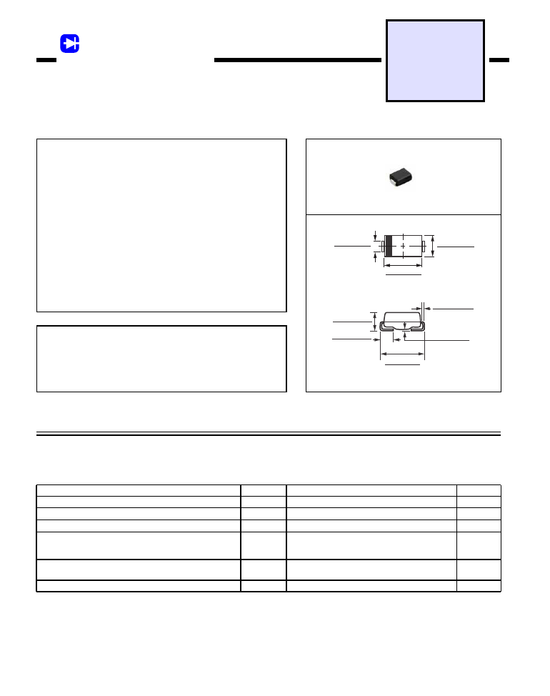
DO-214AA
600 WATT PEAK POWER 5.0 WATTS STEADY STATE
SURFACE MOUNT GPP
GPP TRANSIENT VOLTAGE SUPPRESSOR
Dimensions in inches and (millimeters)
MAXIMUM RATINGS (At T
A
= 25
o
C unless otherwise noted)
DEVICES FOR BIPOLAR APPLICATIONS
For Bidirectional use C or CA suffix for types TFMBJ5.0 thru TFMBJ170
Electrical characteristics apply in both direction
2002-12
Ratings at 25
o
C ambient temperature unless otherwise specified.
3. Lead temperature at T
L
= 25
o
C
NOTES :
2. Mounted on 0.2 X 0.2”( 5.0 X 5.0mm ) copper pad to each terminal.
1. Non-repetitive current pulse, per Fig.3 and derated above T
A
= 25
o
C per Fig.2.
4. Measured on 8.3mS single half sine-wave duty cycle = 4 pules per minute maximum.
5. V
F
= 3.5V on TFMBJ-5.0 thru TFMBJ-90 devices and V
F
= 5.0V on TFMBJ-100 thru TFMBJ-170 devices.
RATINGS
Steady State Power Dissipation at T
L
= 75
o
C (Note 2)
Peak Pulse Current with a 10/1000uS waveform ( Note 1, Fig.3 )
Maximum Instantaneous Forward Voltage at 50A for unidirectional
only (Note 3,4)
SYMBOL
I
FSM
V
F
T
J
, T
STG
Volts
-55 to + 150
0
C
U N I T S
Amps
Peak Power Dissipation with a 10/1000uS (Note 1,2, Fig.1)
Minimum 600
100
SEE NOTE 4
VALUE
Operating and Storage Temperature Range
P
PPM
Watts
I
PPM
Amps
SEE TABLE 1
Peak Forward Surge Current 8.3mS single half sine-wave
superimposed on rated load (JEDEC method) (Note 2,3)
unidirectional only
P
M
(AV)
5.0
Watts
0.012 (0.305)
0.006 (0.152)
0.008 (0.203)
0.004 (0.102)
0.220 (5.59)
0.205 (5.21)
0.030 (0.76)
0.060 (1.52)
0.084 (2.13)
0.096 (2.44)
0.160 (4.06)
0.180 (4.57)
0.130 (3.30)
0.155 (3.94)
0.083 (2.11)
0.077 (1.96)