1
Non resettable fuses
UMT 250
Fuses
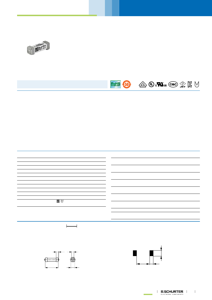
Surface Mount Fuse, 3 x 10.1 mm, Time-Lag T, 250 VAC, 125 VDC
IEC 60127-4 · 250 VAC · 125 VDC · Time-Lag T
Description
- High current range from 80 mA to 10 A
- High breaking capacity of 200 A @ 250 VAC (IEC)
- UL approval for 277 VAC and 250 VDC
Unique Selling Proposition
- Most compact design for primary and secondary protection on PCB
- Maximum breaking capacity at minimal footprint
- Suitable for highest breaking capacity up to 200A @ 250 VAC resp.
100 A @ 125 VDC
Standards
- IEC 60127-4/2
- UL 248-14
- CSA C22.2 no. 248.14
Approvals
- VDE Certificate Number: 40013121
- UL File Number: E41599
Applications
- Primary protection on SMD PCBs
- Industrial electronic
- Medical equipment
References
Weblinks
,
,
Technical Data
Rated Voltage
250 VAC, 125 VDC
Rated current
0.08 - 10 A
Breaking Capacity
35 A - 200 A
Characteristic
Time-Lag T
Mounting
PCB,SMT
Admissible Ambient Air Temp. -55 °C to 125 °C
Climatic Category
55/125/21 acc. to IEC 60068-1
Material: Housing
Ceramic
Material: Terminals
Tin-Plated Copper Alloy
Unit Weight
0.23 g
Storage Conditions
0 °C to 60 °C, max. 70% r.h.
Product Marking
, Rated current, Voltage, Cha-
racteristic, Breaking Capacity
Soldering Methods
Reflow, Wave
Solderability
245 °C / 3 sec acc. to IEC 60068-2-58,
Test Td
Resistance to Soldering Heat
260 °C / 40 sec acc. to IPC/JEDEC J-
STD-020D, 1 cycle
Life Test
MIL-STD-202, Method 108A
(1000h @ 0.42*In @ 70°C)
Moisture Resistance Test
MIL-STD-202, Method 106E
(50 cycles in a temp./mister chamber)
Terminal Strength
MIL-STD-202, Method 211A
(Deflection of board 1 mm for 1 minute)
Mechanical Shock
MIL-STD-202, Method 213B
(Shock 50g, half sine wave, 11 ms)
Resistance to Solvents
MIL-STD-202, Method 215A
Flammability
min. UL 94V-1
(acc. to EIA/IS-722, Test 4.12)
Dimension
10.1 mm
10.1
1.6
0.4
1.43
3
2
6.5
3.75
Soldering pads