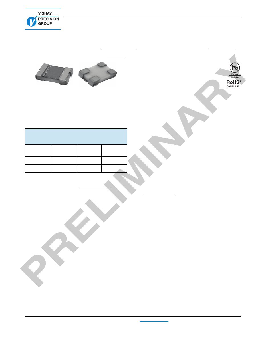
High Precision Foil Surface Mount Current Sensing Chip
Resistors with TCR of ± 2 ppm/°C, Load Life Stability of ± 0.02 %,
ESD Immunity up to 25 kV and Fast Thermal Stabilization
VCS1610 (Kelvin Connection)
Vishay Foil Resistors
Document Number: 63137
For any questions, contact:
foil@vishaypg.com
www.foilresistors.com
Revision: 25-Mar-10
1
TERMINATIONS
Two lead (Pb)-free options are available:
Gold plated or tin plated
Tin/lead plated
Note
• Tighter tolerances and higher values are available. Please
contact application engineering
foil@vishaypg.com
FEATURES
Temperature coefficient of resistance (TCR):
± 2.0 ppm/°C typical (- 55 °C to + 125 °C,
+ 25 °C ref.) (see table 1)
Tolerance: to ± 0.5 %
Load life stability:
± 0.02 % at 70 °C, 2000 h at rated power
Power rating: 0.25 W at + 70 °C
Resistance range: 0.1
to 1
(for higher or lower
values please contact Vishay application engineering
department)
Vishay Foil resistors are not restricted to standard values;
specific “as required” values can be supplied at no extra
cost or delivery (e.g. 0.2345
vs. 0.2
)
Electrostatic discharge (ESD) up to 25 000 V
Thermal stabilization time < 1 s
Short time overload
0.005 %
Non-inductive, non-capacitive design
Thermal EMF: 0.05 µV/°C typical
Current noise: < - 42 dB
Rise time: 1 ns effectively no ringing
Voltage coefficient: < 0.1 ppm/V
Non inductive: < 0.08 µH
Weight: 0.027 mg
Compliant to RoHS directive 2002/95/EC
Prototype quantities available in just 5 working days
or sooner. For more information, please contact
foil@vishaypg.com
For improved performances, please see VCS1610Z
INTRODUCTION
Why should I use the VCS1610?
The VCS1610 is a current sensing solution that was
developed with a low TCR to meet demands for new and
stable resistive product solutions in the industry today. This
resistor is most-often used to monitor a current that is directly
proportional to some physical characteristic (such as
pressure, weight, etc) being measured by an analog sensor.
The resistor converts the current to a voltage that is
representative of the physical characteristic and feeds that
voltage into control circuits, instrumentation, or other
indicators.
Variations induced in the resistor, not representative of the
monitored characteristic, can be caused by high TCR
response to both ambient temperature and self-heating and
can feed erroneous signals into the system. Resistance is
usually kept low to reduce the I²R self-heating (Joule effect)
portion of the error while minimizing the stresses that cause
long-term resistance changes. It is critical for this resistor to
reach thermal equilibrium quickly in circuits that require fast
response or where the current changes quickly.
The VCS1610 is used where the emphasis is on accuracy
and repeatability under stress conditions in applications
requiring precision resistor performance up to 0.25 W and up
to 70 °C. Applications as EB systems, switching power
supplies, force-balanced scales all rely on current sense
resistors to develop a precise voltage proportional to the
current. The VCS1610 is a four terminal resistor which is
essential to achieve high accuracy and stability.
Why use Kelvin connections?
Four-terminal connections or Kelvin connections are
required in these low ohmic value resistors to measure a
precise voltage drop across the resistive element. The
4-terminal configuration eliminates the IR-drop error voltage
that would be present in the voltage sense leads if a standard
two-terminal resistor were used.
In current sense resistors the contact resistance and the
terminations resistance may be greater than that of the
resistive element itself so lead connection errors can be
significant if only two terminal connections are used.
* Pb containing terminations are not RoHS compliant, exemptions may apply
TABLE 1 - TOLERANCE AND TCR VS.
RESISTANCE VALUE
(- 55 °C to + 125 °C, + 25° Ref.)
VALUE
(
)
TOLERANCE
TYPICAL
TCR
MAXIMUM
TCR
0R5 to 1R
0.5 %, 1 %
± 2 ppm/°C
± 10 ppm/°C
0R1 to 0R5
0.5 %, 1 %
± 2 ppm/°C
± 15 ppm/°C
VCS1610 (Kelvin Connection)
Vishay Foil Resistors
www.foilresistors.com
For any questions, contact:
foil@vishaypg.com
Document Number: 63137
2
Revision: 25-Mar-10
Why is the VCS1610 vital to avoid Thermal EMF
(parasitic effect)?
When the junction of two dissimilar metals is heated, a
voltage is generated across the junction creating a DC-offset
error signal. This voltage is proportional to the temperature
difference across the junction and is called a Thermal
Electro-motive Force (Thermal EMF), or thermocouple.
Thermal EMF is an important consideration in low ohmic
current sensing resistors used mostly in DC circuits (there is
no effect in AC circuitry). The VCS1610 is the ideal solution
to minimize the effect of thermal EMF through the use of
appropriate materials between the resistive layer and the
terminations.
Should I be concerned about ESD impact on my
resistor?
Electrostatic Discharge (ESD) is known to produce
catastrophic failures in thin-film and thick-film (cermet)
resistors at only 3000 V. On the other hand, the Bulk Metal
Foil resistor withstands ESD events up to 25 000 V because
its thicker resistance element and greater metallic mass
afford much higher energy-handling capability than either the
much thinner thin-film resistor or the sparse,
non-homogeneous metallic content of the thick film resistor.
Should I be concerned about stability?
In order to select the resistor technology most appropriate to
the application, a designer must take into account all normal
and extraordinary stresses the resistor will experience in the
application. In addition, the designer must consider the cost
and reliability impact involved when it becomes necessary to
add costly additional compensating circuitry when
inadequate resistors are selected. The stability of Bulk Metal
Foil resistors, together with the advantages already
mentioned, as well as the other basic advantages apparent
in their specifications will not only provide unequalled
performance in the circuit but will eliminate all the costs
associated with extra compensation circuitry.
With VCS1610, only a minimal shift in resistance value will
occur during its entire lifetime. Most of this shift takes place
during the first few hundred hours of operation, and virtually
no change is noted thereafter.
Note
(1)
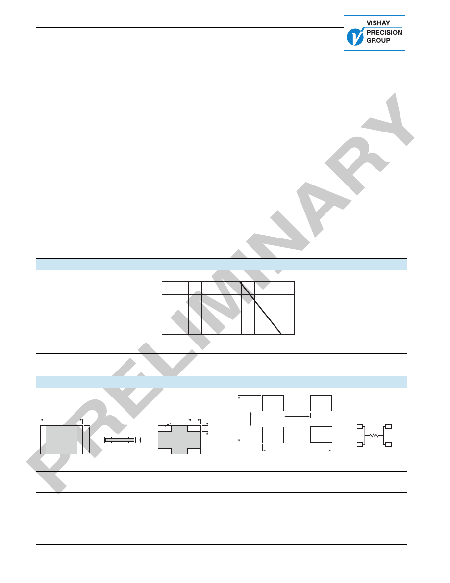
Power rating: 0.25 W at + 70 °C
FIGURE 1 - POWER DERATING CURVE
(1)
100
75
50
25
0
- 75
- 50
- 25
0
+ 25
+ 50
+ 75 + 100 + 125 + 150 + 175
Ambient Temperature (°C)
Percent of Rated Power
+ 70 °C
- 55 °C
FIGURE 2 - DIMENSIONS
in inches (millimeters)
INCHES
MILLIMETERS
L
0.160 ± 0.010
4.06 ± 0.25
H
0.100 ± 0.010
2.54 ± 0.25
W
0.040 maximum
1.02 maximum
A
0.045 ± 0.005
1.14 ± 0.13
B
0.030 ± 0.010
0.76 ± 0.25
W
L
H
Top View
A
B
E
1
I
1
Bottom View
Mountin
g
Pads (4)
I
2
E
2
Solder Pad Layout
0.110
0.200
(5.08)
(2.794)
0.020
(0.508)
0.060
(1.524)
I
1
E
2
E
1
I
2
R
Electrical Schematic
VCS1610 (Kelvin Connection)
Vishay Foil Resistors
Document Number: 63137
For any questions, contact:
foil@vishaypg.com
www.foilresistors.com
Revision: 25-Mar-10
3
Note
• Measurement error 0.001 R
Note
(1)
For non-standard requests or additional values, please contact application engineering.
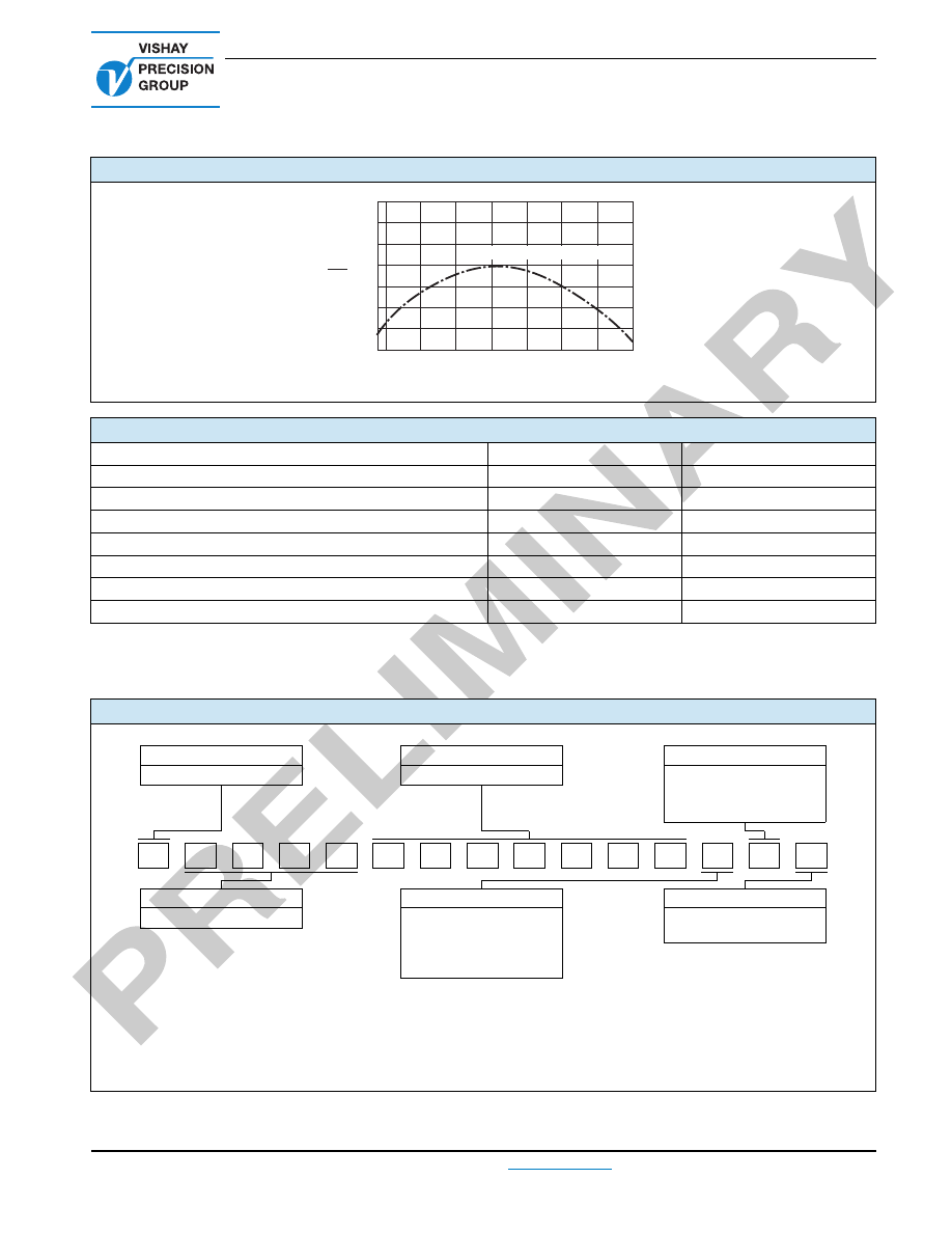
FIGURE 3 - TYPICAL RESISTANCE/TEMPERATURE CURVE
TABLE 2 - PERFORMANCE SPECIFICATIONS
TEST
MIL-PRF-55342
R LIMITS
TYPICAL
R LIMITS
Thermal Shock 5 x (- 65 °C to + 150 °C)
± 0.10 %
± 0.005 % (50 ppm)
Low Temperature Operation
± 0.10 %
± 0.005 % (50 ppm)
Short Time Overload
± 0.10 %
± 0.005 % (50 ppm)
High Temperature Exposure
± 0.10 %
± 0.01 % (100 ppm)
Resistance to Soldering Heat
± 0.2 %
± 0.01 % (100 ppm)
Moisture Resistance
± 0.2 %
± 0.01 % (100 ppm)
Load Life 2000 h at 70 °C
± 0.5 %
± 0.02 % (200 ppm)
TABLE 3 - GLOBAL PART NUMBER INFORMATION
(1)
NEW GLOBAL PART NUMBER: Y11200R40500D9W (preferred part number format)
DENOTES PRECISION
VALUE
CHARACTERISTICS
Y
R
=
0
= tin/lead plated
9
= tin plated
19
= gold plated
1 to 999
= custom
PRODUCT CODE
RESISTANCE TOLERANCE
PACKAGING
1120
= VCS1610
D
= ± 0.5 %
F
= ± 1.0 %
G
= ± 2.0 %
J
= ± 5.0 %
K
= ± 10.0 %
W
= waffle pack
R
= tape and reel
FOR EXAMPLE: ABOVE GLOBAL ORDER Y1120 0R40500 D 9 W:
TYPE: VCS1610
VALUES: 0.405
ABSOLUTE TOLERANCE: ± 0.5 %
TERMINATION: lead (Pb)-free
PACKAGING: waffle pack
+ 75
+ 150
+ 100
+ 50
0
- 50
- 100
- 150
- 200
Ambient Temperature (°C)
Δ
R
R
(ppm)
± 2 ppm/°C (+ 25 °C Reference)
+ 100
+ 125
- 25
0
+ 25
+ 50
- 50
1
2
0
0
4
0
5
R
Y
1
0
9
0
W
D

Vishay Precision Group
Document No.: 63999
Revision: 27-Apr-2011
www.vishaypg.com
1
Legal Disclaimer Notice
Disclaimer
Legal Disclaimer Notice
Disclaimer
Document No.: 63999
Revision: 27-Apr-2011
ALL PRODUCTS, PRODUCT SPECIFICATIONS AND DATA ARE SUBJECT TO CHANGE WITHOUT NOTICE.
Vishay Precision Group, Inc., its affiliates, agents, and employees, and all persons acting on its or their
behalf (collectively, “Vishay Precision Group”), disclaim any and all liability for any errors, inaccuracies or
incompleteness contained herein or in any other disclosure relating to any product.
The product specifications do not expand or otherwise modify Vishay Precision Group’s terms and
conditions of purchase, including but not limited to, the warranty expressed therein.
Vishay Precision Group makes no warranty, representation or guarantee other than as set forth in the terms
and conditions of purchase.
To the maximum extent permitted by applicable law, Vishay Precision
Group disclaims (i) any and all liability arising out of the application or use of any product, (ii) any and
all liability, including without limitation special, consequential or incidental damages, and (iii) any and
all implied warranties, including warranties of fitness for particular purpose, non-infringement and
merchantability.
Information provided in datasheets and/or specifications may vary from actual results in different
applications and performance may vary over time. Statements regarding the suitability of products for
certain types of applications are based on Vishay Precision Group’s knowledge of typical requirements that
are often placed on Vishay Precision Group products. It is the customer’s responsibility to validate that a
particular product with the properties described in the product specification is suitable for use in a particular
application.
No license, express, implied, or otherwise, to any intellectual property rights is granted by this document, or
by any conduct of Vishay Precision Group.
The products shown herein are not designed for use in life-saving or life-sustaining applications unless
otherwise expressly indicated. Customers using or selling Vishay Precision Group products not expressly
indicated for use in such applications do so entirely at their own risk and agree to fully indemnify Vishay
Precision Group for any damages arising or resulting from such use or sale. Please contact authorized
Vishay Precision Group personnel to obtain written terms and conditions regarding products designed for
such applications.
Product names and markings noted herein may be trademarks of their respective owners.