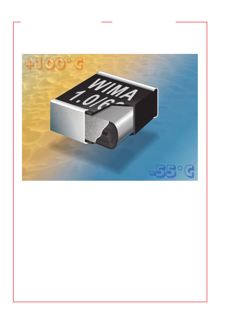
background image

16

01-04

Der SMD-Baustein
auf den Sie bauen können

WIMA SMD-Reihen decken nahezu den gesamten Anwendungsbe-
reich konventionell bedrahteter Kunststofffolien-Kondensatoren ab.

Mit den Size Codes 1812, 2220 und 2824 stehen miniaturisierte
Bauelemente zur Verfügung, deren Kapazitätsreihen Werte bis 2,2 

m

F

und Nennspannungen bis 250 V- abdecken. Für erhöhte Anforder-
ungen sind die Size Codes 4030 bis 6560 ausgelegt, die ein Kapa-
zitätsspektrum bis 6,8 

m

F und Spannungen bis 1000 V- aufweisen.-

SMD Metallpapier Funk-Entstörkondensatoren sind mit Kapazitäten
von 1000 bis 4700 pF/250 V

Z

 im Size Code 6560 erhältlich.

Alle WIMA SMD-Reihen sind in Becher-Technologie gefertigt, 
die im Vergleich zu nichtumhüllten oder umpreßten SMD-Aus-
führungen wesentliche Vorteile aufweist:

˜

 Schutz des Kondensatorelements vor mechanischen Belastun-

gen während des Verarbeitungsprozesses und des Betriebs.

˜

 Keine Gefahr interner Cracks aufgrund der konstruktionsbe-

dingten Elastizität des Aufbaus.

˜

 Keine Delaminationsgefahr durch ganzseitige, metallische

SMD-Anschlußbleche.

˜

 Flammhemmendes Kunststoffgehäuse gemäß UL 94 V-0.

Aufgrund dieser positiven Eigenschaften können WIMA SMDs 
andere Kondensatorentechniken substituieren und sich als de 
facto Standard in Elektronik-Entwicklungen etablieren.

WIMA SMD capacitor ranges cover nearly the entire application 
range of conventionally leaded plastic film capacitors.

With size codes 1812, 2220 and 2824, miniaturized capacitors
with capacitances up to 2.2 

m

F and rated voltages up to 250 VDC

are  available.  The  size  codes  4030  through  6560  are  designed
for special requirements and show capacitance values up to
6.8 

m

F and voltage ranges up to 1000 VDC. SMD RFI capacitors 

with metallized paper dielectric are available in size code 6560 
with capacitances of 1000 pF through 4700 pF/250 VAC.

All WIMA SMD series are produced with the proven box 
technology, showing the following advantages in comparison 
with non-encapsulated or moulded SMD capacitor versions:

˜

 Safe protection of the capacitor element against

mechanical stresses during processing and operation.

˜

 No danger of internal cracks or tearing away of the contacts

due to construction elasticity.

˜

 No danger of delamination due to solder tabs over the

capacitor‘s entire end surfaces.

˜

 Flame-retardent plastic case in accordance with UL 94 V-0.

These features and the wide capacitance range enable WIMA 
SMDs to substitute other capacitor technologies and become 
standard components in electronic developments.

The SMD component
you can rely on

wima_smd_capacitors-html.html
background image

17

01-04

Metallisierte Polyester-SMD Konden-
satoren mit Becherumhüllung

˜

 Für allgemeine Anwendungen wie Koppeln, Ent-

koppeln  und  Abblocken. 

˜

  Kapazitätsspektrum: 

1000 pF - 0,47 

m

F. 

˜

 Ganzseitige Lötflächen. 

˜

 Ge-

gurtet lieferbar im 12 mm Blistergurt.

Metallized polyester SMD capacitors
with plastic box encapsulation

˜

 For general applications e.g. coupling, decoupling

and  by-pass  applications. 

˜

  Capacitance  range: 

1000 pF - 0.47 

m

F. 

˜

 Full size soldering surfaces. 

˜


Available taped and reeled in 12 mm blister pack.

Technische Angaben

Dielektrikum:

 Polyäthylenterephthalat-Folie.

Beläge:

 Aluminium, aufmetallisiert.

Umhüllung:

 Flammhemmendes Kunststoffgehäuse, UL 94 V–0, 

Farbe: Schwarz.

Temperaturbereich:

 –55

)

 C bis +100

)

 C.

Prüfungen: 

Nach IEC 60384-19 bzw. 

EN 132 200.

Prüfklasse:

 55/100/21 nach IEC.

Isolationswerte

 bei +20° C:


U

N

        U

meß

          C 

 0,33 

m

F               C 

=

 0,47 

m

F


    63 V- 

  50 V       

 3,75 

 10

3

 M


1250 s (M

V


m

F) 

100 V- 

100 V    Mittelwert: 1 

 10

4

 M

Mittelwert: 3000 s

Nach IEC 60384-19 und EN 132 200
Meßzeit: 1 min.

Kapazitätstoleranzen:


±

 20 %, 

±

 10 %,

(

±

 5 % auf Anfrage).

Impulsbelastung:


C-Wert


Flankensteilheit V/

m

s


pF/

m

F


max. Betrieb/Prüfung


63 V– 

100 V– 

250 V–

  1000   . . . 6800 

20/200 

20/200 

20/200

  0,01   . . . 0,022 

15/150 

20/200 

20/200

  0,033 . . . 0,068 

10/100 

15/150 

-

  0,1     . . . 0,15 

5/50 

10/100 

-

  0,22   . . . 0,47 

2/20 

6/60 

-

bei vollem Spannungshub.

Verlustfaktoren

 bei +20

)

 C: tan 

d

 Gemessen bei 

 0,1 

m

0,1 

m

F


    1 kHz 

   8 

 10

-3


   8 

 10

-3


  10 kHz 

 15 

 10

-3


 15 

 10

-3


100 kHz 

 30 

 10

-3


Temperaturcharakteristik:

 Siehe Kurven Seite 33.

Prüfspannung:

 1,6 U

N

 , 2 s.

Spannungsderating:

 Die zulässige Spannung vermindert sich 

gegenüber der Nennspannung bei Gleichspannungsbetrieb ab 
+85

)

 C, bei Wechselspannungsbetrieb ab +75

)

 C um 1,25 % 

je 1 K.

Lötwärmebeständigkeit:

 Temperatur des Lötbades max. 260 ° C.

Lötdauer max. 5 s. Kapazitätsänderung 

D

C/C < 3 %.

Prüfung Tb nach DIN IEC 60068-2-20 und EN 132 200.

Löttechnik:

 Wellenlötung und Reflowlötung

(siehe Temperatur/Zeitdiagramm Seite 30).

Technical Data

Dielectric:

 Polyethylene-terephthalate film.

Capacitor electrodes:

 Vacuum-deposited aluminium.

Encapsulation:

 Flame retardent plastic case, UL 94 V–0, 

Colour: Black.

Temperature range:

 –55

)

 C to +100

)

 C.

Test specifications: 

In accordance with IEC 60384-19 

and EN 132 200.

Test category:

 55/100/21 in accordance with IEC.

Insulation resistance

 at +20° C:


U

r


U

test


 0.33 

m

=

 0.47 

m

F


    63 VDC    50 V 

 3.75 x 10

3

 M


1250 sec (M

m

F) 

100 VDC  100 V  Mean value: 1x10

4

 M

Mean value: 3000 sec

In accordance with IEC 60384-19 and EN 132 200.
Measuring time: 1 min.

Capacitance tolerances:


±

 20 %, 

±

 10 %, (

±

 5 % available 

subject to special enquiry).

Maximum pulse rise time:


Capacitance


Pulse rise time V/

m

sec


pF/

m

F


max. operation/test


63 VDC 

100 VDC 

250 VDC

  1000   . . . 6800 

20/200 

20/200 

20/200

  0.01   . . . 0.022 

15/150 

20/200 

20/200

  0.033 . . . 0.068 

10/100 

15/150 

-

  0.1     . . . 0.15 

5/50 

10/100 

-

  0.22   . . . 0.47 

2/20 

6/60 

-

for pulses equal to the rated voltage.

Dissipation factors

 at +20

)

 C: tan 

d


at f 

 0.1 

m

0.1 

m

F


    1 kHz 

   8 x 10

-3


   8 x 10

-3


  10 kHz 

 15 x 10

-3


 15 x 10

-3


100 kHz 

 30 x 10

-3


Temperature characteristics:

 See graph page 33.

Test voltage:

 1.6 U

r

 , 2 sec.

Voltage derating:

 A voltage derating factor of 1.25 % per K 

must be applied from +85

)

 C for DC voltages and from +75 

)

 C

for AC voltages.

Resistance to soldering heat:


Solder bath temperature max. 260 ° C.
Soldering duration max. 5 sec. Change in capacitance 

D

C/C < 3 %.

In accordance with DIN IEC 60068-2-20 (test Tb.)/EN 132 200.

Soldering process:

 Wave soldering and re-flow soldering

(see temperature/time graphs page 30).

  WIMA SMD 1812

wima_smd_capacitors-html.html
background image

18

01-04

WIMA SMD 1812

Werteübersicht / General Data


Kapazität


63 VDC/40 VAC * 


100 VDC/63 VAC * 


  250 VDC/160 VAC *


Capacitance


H


± 0.3 

± 0.3 

± 0.3 

± 0.3 

± 0.3 

± 0.3 

± 0.3 

± 0.3 

± 0.3


1000   pF 

4.8


3.3 

4.8


3.3 

4.8


3.3 

2


1500   „ 

4.8


3.3 

4.8


3.3 

4.8


3.3 

2


2200   „ 

4.8


3.3 

4.8


3.3 

4.8


3.3 

3


3300   „ 

4.8


3.3 

4.8


3.3 

4.8


3.3 

3


4700   „ 

4.8


3.3 

4.8


3.3 

4.8


3.3 

3


6800   „ 

4.8


3.3 

4.8


3.3 

4.8


3.3 

3


0.01   

m

4.8


3.3 

4.8


3.3 

4.8


3.3 

4


0.015 „ 

4.8


3.3 

4.8


3.3 

4.8


3.3 

4


0.022 „ 

4.8


3.3 

4.8


3.3 

4.8


3.3 

4


0.033 „ 

4.8


3.3 

4.8


3.3 

3


0.047 „ 

4.8


3.3 

4.8


3.3 

3


0.068 „ 

4.8


3.3 

4.8


3.3 

3


0.1     

m

4.8


3.3 

4.8


3.3 

3


0.15   „ 

4.8


3.3 

4.8


3.3 

4


0.22   „ 

4.8


3.3 

4.8


3.3 

4


0.33   „ 

4.8


3.3 

4


0.47   „ 

4.8


3.3 

4

* Wechselspannungen: f = 50 Hz; 1,4 

 U

eff


Z

 + U– 

 U

N

* AC voltage: f = 50 Hz, 1.4 x U

rms

 + UDC 

 U

r

Gegurtete Ausführung siehe Seite 29.
Taped version see page 29.

Alle Maße in mm.
Dims. in mm.

Lötpadempfehlung.
Solder pad recommendation.

Abweichungen und Konstruktionsänderungen vorbehalten.
Rights reserved to amend design data without prior notification.

1

10

100               1000

f/MHz

3     5  7

3     5  7

7
5
3

7
5
3

10

1

0.1

0.01

Z

S

-- 1

00

0 p

F

-- 2

20

0 p

F

-- 4

70

0 p

F

-- 0

.0

1 µ

F

-- 0

.0

22

 µF

-- 0

.0

47

 µF

-- 0

.1

 µF

-- 0

.2

2 µ

F

-- 0

.4

7 µ

F

Scheinwiderstand in Abhängigkeit von 
der Frequenz (Richtwerte).

Impedance change with frequency
(general guide).

H

W

L

0.5

0.5

3.5

3.5

1.2

Klebespalt

Bonding slit

wima_smd_capacitors-html.html
background image

19

01-04

  WIMA SMD 2220

Metallisierte Polyester-SMD Konden-
satoren mit Becherumhüllung

˜

 Für allgemeine Anwendungen wie Koppeln, Ent-

koppeln  und  Abblocken.   

˜

  Kapazitätsspektrum: 

1000 pF - 1,0 

m

F.  

˜

 Ganzseitige Lötflächen.  

˜

 Ge-

gurtet lieferbar im 12 mm Blistergurt.

Metallized polyester SMD capacitors
with plastic box encapsulation

˜

 For general applications e.g. coupling, decoupling

and  by-pass  applications.   

˜

  Capacitance  range: 

1000  pF  -  1.0 

m

F.   

˜

  Full  size  soldering  surfaces.

˜

  Available  taped  and  reeled  in  12  mm  blister 

pack.

Technische Angaben

Dielektrikum:

 Polyäthylenterephthalat-Folie.

Beläge:

 Aluminium, aufmetallisiert.

Umhüllung:

 Flammhemmendes Kunststoffgehäuse, UL 94 V–0, 

Farbe: Schwarz.

Temperaturbereich:

 –55

)

 C bis +100

)

 C.

Prüfungen: 

Nach IEC 60384-19 bzw. 

EN 132 200.

Prüfklasse:

 55/100/21 nach IEC.

Isolationswerte

 bei +20° C:


U

N

        U

meß

          C 

 0,33 

m

F         0,33 

m

F < C 

 1,0 

m

F

      63 V- 

  50 V      

 3,75 

 10

3

 M

1250 s (M

V


m

F) 


100 V- 

100 V    Mittelwert: 1 

 10

4

 M

Mittelwert: 3000 s

Nach IEC 60384-19 und EN 132 200
Meßzeit: 1 min.

Kapazitätstoleranzen:


±

 20 %, 

±

 10 %, 

(

±

 5 % auf Anfrage).

Impulsbelastung:


C-Wert


Flankensteilheit V/

m

s


pF/

m

F


max. Betrieb/Prüfung


63 V– 

100 V– 

250 V–

  1000   . . . 6800 

35/350 

40/400

  0,01   . . . 0,022 

30/300 

35/350

  0,033 . . . 0,068 

20/200 

25/250

  0,1     . . . 0,22 

5/50 

10/100 

15/150

  0,33   . . . 1,0 

2/20 

6/60 

10/100

bei vollem Spannungshub.

Verlustfaktoren

 bei +20

)

 C: tan 

d

  Gemessen bei 

 0,1 

m

0,1 

m

<

 C 

 1,0 

m

F


    1 kHz 

   8 

 10

-3


   8 

 10

-3


  10 kHz 

 15 

 10

-3


 15 

 10

-3


100 kHz 

 30 

 10

-3


Temperaturcharakteristik:

 Siehe Kurven Seite 33.

Prüfspannung:

 1,6 U

N

 , 2 s.

Spannungsderating:

 Die zulässige Spannung vermindert sich 

gegenüber der Nennspannung bei Gleichspannungsbetrieb ab 
+85

)

 C, bei Wechselspannungsbetrieb ab +75

)

 C um 1,25 % 

je 1 K.

Lötwärmebeständigkeit:

 Temperatur des Lötbades max. 260 ° C.

Lötdauer max. 5 s. Kapazitätsänderung 

D

C/C < 3 %.

Prüfung: Tb nach DIN IEC 60068-2-20 und EN 132 200.

Löttechnik:

 Wellenlötung und Reflowlötung

(siehe Temperatur/Zeitdiagramm Seite 30).

Technical Data

Dielectric:

 Polyethylene-terephthalate film.

Capacitor electrodes:

 Vacuum-deposited aluminium.

Encapsulation:

 Flame retardent plastic case, UL 94 V–0, 

Colour: Black.

Temperature range:

 –55

)

 C to +100

)

 C.

Test specification: 

In accordance with IEC 60384-19 

and EN 132 200.

Test category:

 55/100/21 in accordance with IEC.

Insulation resistance

 at +20° C:


U

r

          U

test

          C 

 0.33 

m

F          0.33 

m

F < C 

 1.0 

m

F

     63 VDC    50 V      

 3.75 x 10

3

 M

1250 sec (M

m

F) 


100 VDC  100 V   Mean value: 1x10

4

 M

Mean value: 3000 sec

In accordance with IEC 60384-19 and EN 132 200
Measuring time: 1 min.

Capacitance tolerances:


±

 20 %, 

±

 10 %, (

±

 5 % available 

subject to special enquiry).

Maximum pulse rise time:


Capacitance


Pulse rise time V/

m

sec


pF/

m

F


max. operation/test


63 VDC 

100 VDC 

250 VDC

  1000   . . . 6800 

35/350 

40/400

  0.01   . . . 0.022 

30/300 

35/350

  0.033 . . . 0.068 

20/200 

25/250

  0.1     . . . 0.22 

5/50 

10/100 

15/150

  0.33   . . . 1.0 

2/20 

6/60 

10/100

for pulses equal to the rated voltage.

Dissipation factors

 at +20

)

 C: tan 

d


at f 

 0.1 

m

0.1 

m

<

 C 

 1.0 

m

F


    1 kHz 

   8 x 10

-3


   8 x 10

-3


  10 kHz 

 15 x 10

-3


 15 x 10

-3


100 kHz 

 30 x 10

-3


Temperature characteristics:

 See graph page 33.

Test voltage:

 1.6 U

r

 , 2 sec.

Voltage derating:

 A voltage derating factor of 1.25 % per K 

must be applied from +85

)

 C for DC voltages and from +75 

)

 C

for AC voltages.

Resistance to soldering heat:

Solder bath temperature max. 260 ° C.
Soldering duration max. 5 sec. Change in capacitance 

D

C/C < 3 %.

In accordance with DIN IEC 60068-2-20 (test Tb.)/EN 132 200.

Soldering process:

 Wave soldering and re-flow soldering

(see temperature/time graphs page 30).

wima_smd_capacitors-html.html
background image

20

01-04

WIMA SMD 2220


Kapazität


63 VDC/40 VAC * 

100 VDC/63 VAC * 

250 VDC/160 VAC *


Capacitance


H


± 0.3 

± 0.3 

± 0.3 

± 0.3 

± 0.3 

± 0.3 

± 0.3 

± 0.3 

± 0.3


1000 pF 


5.7

              5.1              2.5 

5.7


  5.1 

2.5


1500 „ 


5.7

              5.1              2.5 

5.7


  5.1 

2.5


2200 „ 


5.7

              5.1              2.5 

5.7


  5.1 

2.5


3300 „ 


5.7

              5.1              2.5 

5.7


  5.1 

2.5


4700 „ 


5.7

              5.1              2.5 

5.7


  5.1 

2.5


6800 „ 


5.7

              5.1              2.5 

5.7


  5.1 

2.5


0.01   

m


5.7

              5.1              2.5 

5.7


  5.1 

2.5


0.015 „ 


5.7

              5.1              2.5 

5.7


  5.1 

2.5


0.022 „ 


5.7

              5.1              2.5 

5.7


  5.1 

2.5


0.033 „ 


5.7

              5.1              2.5 

5.7


  5.1 

2.5


0.047 „ 


5.7

              5.1              2.5 

5.7


  5.1 

2.5


0.068 „ 


5.7

              5.1              2.5 

5.7


  5.1 

2.5


0.1     

m

5.7


  5.1               2.5              

5.7

              5.1              3.5 

5.7


  5.1 

3.5


0.15   „ 

5.7


  5.1               2.5              

5.7

              5.1              3.5 

5.7


  5.1 

4.5


0.22   „ 

5.7


  5.1               2.5              

5.7

              5.1              3.5 

5.7


  5.1 

4.5


0.33   „ 

5.7


  5.1               3.5              

5.7

              5.1              4.5


0.47   „ 

5.7


  5.1               3.5              

5.7

              5.1              4.5


0.68   „ 

5.7


  5.1               4.5


1.0     

m

5.7


  5.1               4.5

* Wechselspannungen: f = 50 Hz; 1,4 

 U

eff


Z

 + U– 

 U

N

* AC voltage: f = 50 Hz, 1.4 x U

rms

 + UDC 

 U

Gegurtete Ausführung siehe Seite 29.
Taped version see page 29.

Alle Maße in mm.
Dims. in mm.

Lötpadempfehlung.
Solder pad recommendation.

Abweichungen und Konstruktionsänderungen vorbehalten.
Rights reserved to amend design data without prior notification.

1

10

100              1000

f/MHz

3     5  7

3     5  7

7
5
3

7
5
3

10

1

0.1

0.01

Z

S

-- 1

00

0  

pF

-- 2

20

0  

pF

-- 4

70

0  

pF

-- 0

.0

1  

 µ

F

-- 0

.0

22

 µ

F

-- 0

.0

47

 µ

F

-- 0

.1


 µ

F

-- 0

.2

2  

 µ

F

-- 0

.4

7  

 µ

F

-- 1

.0


 µ

F

Scheinwiderstand in Abhängigkeit von 
der Frequenz (Richtwerte).

Impedance change with frequency
(general guide).

H

W

L

4

4.5

1.2

Klebespalt

Bonding slit

Werteübersicht / General Data

wima_smd_capacitors-html.html
background image

21

01-04

  WIMA SMD 2824

Metallisierte Polyester-SMD Konden-
satoren mit Becherumhüllung

˜

  Für  allgemeine  Anwendungen  wie  Koppeln,

Entkoppeln und Abblocken.  

˜

 Kapazitätsspektrum: 

0,01 

m

F - 2,2 

m

F.  

˜

 Ganzseitige Lötflächen.  

˜

 Ge-

gurtet lieferbar im 12 mm Blistergurt.

Metallized polyester SMD capacitors
with plastic box encapsulation

˜

 For general applications e.g. coupling, decoupling

and  by-pass  applications.   

˜

  Capacitance  range: 

0.01 

m

F  -  2.2 

m

F.   

˜

  Full  size  soldering  surfaces. 

˜

  Available  taped  and  reeled  in  12  mm  blister 

pack.

Technische Angaben

Dielektrikum:

 Polyäthylenterephthalat-Folie.

Beläge:

 Aluminium, aufmetallisiert.

Umhüllung:

 Flammhemmendes Kunststoffgehäuse, UL 94 V–0, 

Farbe: Schwarz.

Temperaturbereich:

 –55

)

 C bis +100

)

 C.

Prüfungen: 

Nach IEC 60384-19 

bzw. EN 132 200.

Prüfklasse:

 55/100/21 nach IEC.

Isolationswerte

 bei +20° C:


U

N

        U

meß

          C 

 0,33 

m

F         0,33 

m

F < C 

 2,2 

m

F

     63 V- 

  50 V      

 3,75 

 10

3

 M

1250 s (M

V


m

F)


100 V- 

100 V    Mittelwert: 1 

 10

4

 M

Mittelwert: 3000 s

Nach IEC 60384-19 und EN 132 200. 
Meßzeit: 1 min.

Kapazitätstoleranzen:


±

 20 %, 

±

 10 %,

(

±

 5 % auf Anfrage).

Impulsbelastung:


C-Wert


  Flankensteilheit V/

m

s


m

F


  max. Betrieb/Prüfung


63 V– 

100 V– 

250 V– 

400 V–

  0,01   . . . 0,022 

30/300 

40/400 

60/600

  0,033 . . . 0,068 

20/200 

40/400 

60/600

  0,1     . . . 0,22 

10/100 

10/100 

20/200 

-

  0,33   . . . 1,0 

2/20 

8/80 

10/100 

-

  1,5     . . . 2,2 

2/20 

-

bei vollem Spannungshub.

Verlustfaktoren

 bei +20

)

 C: tan 

d

 Gemessen bei  C 

 0,1 

m

F  0,1 

m

<

 C 

 1,0 

m

>

1,0 

m

F


    1 kHz 

   8 

 10

-3


   8 

 10

-3


 10 

 10

-3


  10 kHz 

 15 

 10

-3


 15 

 10

-3


100 kHz 

 30 

 10

-3


– 

Temperaturcharakteristik:

 Siehe Kurven Seite 33.

Prüfspannung:

 1,6 U

N

 , 2 s.

Spannungsderating:

 Die zulässige Spannung vermindert sich 

gegenüber der Nennspannung bei Gleichspannungsbetrieb ab 
+85

)

 C, bei Wechselspannungsbetrieb ab +75

)

 C um 1,25 % 

je 1 K.

Lötwärmebeständigkeit:

 Temperatur des Lötbades max. 260 ° C.

Lötdauer max. 5 s. Kapazitätsänderung 

D

C/C < 3 %.

Prüfung: Tb nach DIN IEC 60068-2-20 und EN 132 200.

Löttechnik:

 Wellenlötung und Reflowlötung

(siehe Temperatur/Zeitdiagramm Seite 30).

Technical Data

Dielectric:

 Polyethylene-terephthalate film.

Capacitor electrodes:

 Vacuum-deposited aluminium.

Encapsulation:

 Flame retardent plastic case, UL 94 V–0, 

Colour: Black.

Temperature range:

 –55

)

 C to +100

)

 C.

Test specification: 

In accordance with IEC 60384-19 

and EN 132 200.

Test category:

 55/100/21 in accordance with IEC.

Insulation resistance

 at +20° C:


U

r

          U

test

          C 

 0.33 

m

F          0.33 

m

F < C 

 1.0 

m

F

     63 VDC    50 V      

 3.75 x 10

3

 M

1250 sec (M

V

 x 

m

F)


100 VDC  100 V   Mean value: 1x10

4

 M

Mean value: 3000 sec

In accordance with IEC 60384-19 and EN 132 200.
Measuring time: 1 min.

Capacitance tolerances:


±

 20 %, 

±

 10 %, (

±

 5 % available 

subject to special enquiry).

Maximum pulse rise time:


Capacitance


 Pulse rise time V/

m

sec


m

F


  max. operation/test


63 VDC 

100 VDC  250 VDC  400 VDC

  0.01   . . . 0.022 

30/300 

40/400 

60/600

  0.033 . . . 0.068 

20/200 

40/400 

60/600

  0.1     . . . 0.22 

10/100 

10/100 

20/200 

-

  0.33   . . . 1.0 

2/20 

8/80 

10/100 

-

  1.5     . . . 2.2 

2/20 

-

for pulses equal to the rated voltage.

Dissipation factors

 at +20

)

 C: tan 

d


at f 

 0.1 

m

F  0.1 

m

<

 C 

 1.0 

m

>

1.0 

m

F


    1 kHz 

   8 x 10

-3


   8 x 10

-3


 10 x 10

-3


  10 kHz 

 15 x 10

-3


 15 x 10

-3


100 kHz 

 30 x 10

-3


– 

Temperature characteristics:

 See graph page 33.

Test voltage:

 1.6 U

r

 , 2 sec.

Voltage derating:

 A voltage derating factor of 1.25 % per K 

must be applied from +85

)

 C for DC voltages and from +75 

)

 C

for AC voltages.

Resistance to soldering heat:

Solder bath temperature max. 260 ° C.
Soldering duration max. 5 sec. Change in capacitance 

D

C/C < 3 %.

In accordance with DIN IEC 60068-2-20 (test Tb.)/EN 132 200.

Soldering process:

 Wave soldering and re-flow soldering

(see temperature/time graphs page 30).

wima_smd_capacitors-html.html
background image

22

01-04

WIMA SMD 2824

Werteübersicht / General Data


Kapazität


 63 VDC/40 VAC *  

 100 VDC/63 VAC * 

 250 VDC/160 VAC * 

 400 VDC/200 VAC *


Capacitance


H


± 0.3 

± 0.3 

± 0.3 

± 0.3 

± 0.3 

± 0.3 

± 0.3 

± 0.3 

± 0.3 

± 0.3 

± 0.3 

± 0.3


0.01   

m


7.2


6.1 

7.2


6.1 

7.2


6.1 

3


0.015 „ 


7.2


6.1 

7.2


6.1 

7.2


6.1 

3


0.022 „ 


7.2


6.1 

7.2


6.1 

7.2


6.1 

4


0.033 „ 


7.2


6.1 

7.2


6.1 

7.2


6.1 

5


0.047 „ 


7.2


6.1 

7.2


6.1 

7.2


6.1 

5


0.068 „ 


7.2


6.1 

7.2


6.1 

3


0.1     

m

7.2


6.1 

7.2


6.1 

7.2


6.1 

4


0.15   „ 

7.2


6.1 

7.2


6.1 

7.2


6.1 

4


0.22   „ 

7.2


6.1 

7.2


6.1 

7.2


6.1 

4


0.33   „ 

7.2


6.1 

7.2


6.1 

7.2


6.1 

5


0.47   „ 

7.2


6.1 

7.2


6.1 

4


0.68   „ 

7.2


6.1 

7.2


6.1 

5


1.0     

m

7.2


6.1 

7.2


6.1 

5


1.5     „ 

7.2


6.1 

4


2.2     „ 

7.2


6.1 

5

* Wechselspannungen: f = 50 Hz; 1,4 

 U

eff


Z

 + U– 

 U

N

* AC voltage: f = 50 Hz, 1.4 x U

rms

 + UDC 

 U

r

Gegurtete Ausführung siehe Seite 29.
Taped version see page 29.

Alle Maße in mm.
Dims. in mm.

Lötpadempfehlung.
Solder pad recommendation.

Abweichungen und Konstruktionsänderungen vorbehalten.
Rights reserved to amend design data without prior notification.

H

W

L

0.5

0.5

4

6.5

1.2

Klebespalt

Bonding slit

0.1

1

10                  100

f/MHz

3     5  7

3     5  7

7
5
3

7
5
3

1

0.1

0.01

0.001

Z

S

-- 0

.0

1  

 µF

-- 0

.0

22

 µF

-- 0

.0

47

 µF

-- 0

.1


 µF

-- 0

.2

2  

 µF

-- 0

.4

7  

 µF

-- 1

.0


 µF

-- 2

.2


 µF

Scheinwiderstand in Abhängigkeit von 
der Frequenz (Richtwerte).

Impedance change with frequency
(general guide).

WIMA SMD 7,3 wurde in die Reihe WIMA SMD 2824 integriert.
WIMA SMD 7.3 was integrated in the WIMA SMD 2824 range.

wima_smd_capacitors-html.html
background image

23

01-04

  WIMA SMD 4030
  WIMA SMD 5040
  WIMA SMD 6054

˜

  Für  allgemeine  Anwendungen.   

˜

  Kapazitäts-

spektrum bis 6,8 

m

F.  

˜

 Spannungsreihen bis 1000 V-.

˜

 Gegurtet lieferbar.

Metallisierte Polyester-SMD
Kondensatoren mit Becher-
umhüllung

Metallized polyester SMD 
capacitors with plastic box
encapsulation

Technische Angaben

Dielektrikum:

 Polyäthylenterephthalat-Folie.

Beläge:

 Aluminium, aufmetallisiert.

Umhüllung:

 Flammhemmendes Kunststoffgehäuse, UL 94 V–0, 

Farbe: Schwarz. Aufdruck: Silber.

Temperaturbereich:

 –55

)

 C bis +100

)

 C.

Prüfungen: 

Nach IEC 60384-19 bzw. 

EN 132 200.

Prüfklasse:

 55/100/56 nach IEC.

Isolationswerte

 bei +20° C:


U

N

        U

meß

          C 

 0,33 

m

F         0,33 

m

F < C 

 6,8 

m

F

    63 V- 

  50 V       

 3,75 

 10

3

 M


1250 s (M

V


m

F)

  100 V- 

100 V    Mittelwert: 1 

 10

4

 M

Mittelwert: 3000 s


250 V- 

100 V


 1 

 10

4

 M


3000 s (M

V


m

F) 


       Mittelwert: 5 

 10

4

 M

Mittelwert: 10 000 s

Nach IEC 60384-19 und EN 132 200.
Meßzeit: 1 min.

Kapazitätstoleranzen:


±

 20 %, 

±

 10 %, 

(

±

 5 % auf Anfrage).

Verlustfaktoren

 bei +20

)

 C: tan 

d

 Gemessen bei  C 

 0,1 

m

F  0,1 

m

<

 C 

 1,0 

m

F  C > 1,0 

m

F


    1 kHz 

   8 

 10

-3


   8 

 10

-3 

 10 

 10

-3


  10 kHz 

 15 

 10

-3


 15 

 10

-3 

-


100 kHz 

 30 

 10

-3


-

Temperaturcharakteristik:

 Siehe Kurven Seite 33.

Prüfspannung:

 1,6 U

N

 , 2 s.

Spannungsderating:

 Die zulässige Spannung vermindert sich 

gegenüber der Nennspannung bei Gleichspannungsbetrieb ab
+85

)

 C, bei Wechselspannungsbetrieb ab +75

)

 C um 1,25 % je 1 K.

Lötwärmebeständigkeit:

 Temperatur des Lötbades max. 260 ° C.

Lötdauer max. 5 s. Kapazitätsänderung 

D

C/C < 5 %.

Prüfung Tb nach DIN IEC 60068-2-20 und EN 132 200.

Löttechnik:

 Wellenlötung und Reflowlötung

(siehe Temperatur/Zeitdiagramm Seite 30).

Impulsbelastung 

bei vollem Spannungshub

:

Technical Data

Dielectric:

 Polyethylene-terephthalate film.

Capacitor electrodes:

 Vacuum-deposited aluminium.

Encapsulation:

 Flame retardent plastic case, UL 94 V–0, 

Colour: Black. Marking: Silver.

Temperature range:

 –55

)

 C to +100

)

 C.

Test specification: 

In accordance with IEC 60384-19 

and EN 132 200.

Test category:

 55/100/56 in accordance with IEC.

Insulation resistance

 at +20° C:


U

r

        U

test

          C 

 0.33 

m

F          0.33 

m

F < C 

 6.8 

m

F

    63 VDC    50 V     

 3.75 x 10

3

 M

V  


1250 sec (M

V

 x 

m

F)

  100 VDC   100 V  Mean value: 1x10

4

 M

V

Mean value: 3000 sec


250 VDC 100 V


 1 x 10

4

 M

V    


3000 sec (M

V

 x 

m

F) 


                  Mean value: 5 x10

4

 M

V

Mean value: 10000sec

In accordance with IEC 60384-19 and EN 132 200.
Measuring time: 1 min.

Capacitance tolerances:


±

 20 %, 

±

 10 %, (

±

 5 % available 

subject to special enquiry).

Dissipation factors

 at +20

)

 C: tan 

d


at f 

 0.1 

m

F  0.1 

m

<

 C 

 1.0 

m

F  C > 1.0 

m

F


    1 kHz 

   8 x 10

-3


   8 x 10

-3 

 10 x 10

-3


  10 kHz 

 15 x 10

-3


 15 x 10

-3 

-


100 kHz 

 30 x 10

-3


-

Temperature characteristics:

 See graph page 33.

Test voltage:

 1.6 U

r

 , 2 sec.

Voltage derating:

 A voltage derating factor of 1,25 % per K 

must be applied from +85

)

 C for DC voltages and from +75 

)

 C

for AC voltages.

Resistance to soldering heat:

 Solder bath temperature max. 260° C

Soldering duration max. 5 sec. Change in capacitance 

D

C/C < 5 %.

In accordance with DIN IEC 60068-2-20 (test Tb.)/EN 132 200.

Soldering process:

 Wave soldering and re-flow soldering

(see temperature/time graphs page 30).

Maximum pulse rise time 

for pulses equal to the rated voltage

:

˜

  For  general  applications. 

˜

  Capacitances  up  to

6.8 

m

F. 

˜

 Voltage ranges up to 1000 VDC. 

˜

 Avail-

able taped and reeled.


C-Wert / Capacitance


Flankensteilheit V/

m


Pulse rise time V/

m

sec


m

F


max. Betrieb/Prüfung 


max.operation/test


63 VDC 

100 VDC 

250 VDC 

400 VDC 

630 VDC 

1000 VDC


0.01   . . . 0.022 

40/400 

50/500


0.033 . . . 0.068 

21/210 

25/250 

32/320


0.1     . . . 0.22 

10/100 

12/120 

14/140 

17/170 

-


0.33   . . . 0.68 

6/60 

9/90 

10/100 

-


1.0     . . . 2.2 

3.5/35 

4/40 

7/70 

-


3.3     . . . 6.8 

3/30 

3/30 

-

NEW
NEW
NEW

wima_smd_capacitors-html.html
background image

24

01-04

WIMA SMD

Werteübersicht / General Data


Kapazität 

63 VDC 

100 VDC 

250 VDC/ 

400 VDC 

630 VDC 

1000 VDC

 Capacitance 

40 VAC * 

63 VAC * 

160 VAC * 

200 VAC * 

300 VAC * 

400 VAC *

  0.01   

m


4030 

5040

  0.015 „ 


4030 

5040

  0.022 „ 


5040 

5040

  0.033 „ 


5040 

5040

  0.047 „ 


4030 

5040 

6054

  0.068 „ 


4030 

5040

  0.1     

m


4030 

4030 

6054

  0.15   „ 


4030 

4030 

6054

  0.22   „ 


4030 

4030 

5040 

6054

  0.33   „ 


4030 

4030 

5040

  0.47   „ 


4030 

4030 

6054

  0.68   „ 


4030 

5040

  1.0     

m

4030 

4030 

6054

  1.5     „ 

4030 

4030

  2.2     „ 

4030 

5040 

  3.3     „ 

4030 

5040

  4.7     „ 

5040 

6054

  6.8     „ 

6054

* Wechselspannungen: f = 50 Hz; 1,4 

 U

eff


Z

 + U– 

 U

N

* AC voltage: f = 50 Hz, 1.4 x U

rms

 + UDC 

 U

r

Gegurtete Ausführung siehe Seite 29.
Taped version see page 29.

Alle Maße in mm. / Dims. in mm.

Lötpadempfehlung.
Solder pad recommendation.

Abweichungen und Konstruktionsänderungen vorbehalten. / Rights reserved to amend design data without prior notification.


Size Code

  L 

c


± 

0.3 

± 

0.3 

± 

0.3 


min.  min.  max.


4030 

10.2    7.6 

0.5 

2.5 

 9


5040 

12.7  10.2 

0.7 

2.5 

11.5


6054 

15.3  13.7 

0.7 

2.5 

15

Zulässige Wechselspannung in Abhängigkeit von der Frequenz
bei 10 ° C Eigenerwärmung (Richtwerte).

Permissible AC voltage in relation to frequency
at 10 ° C internal temperature rise (general guide).

H

W

L

d

d

b

c

a

Klebespalt

Bonding slit

63 VDC

f

Hz

10

2

5

10

2

5

10

2

5

10

2

3

4

5

5

2

10

5

2

1

40

Urms

V

1.0

µF

6.8

µF

2.2

µF

100 VDC

f

Hz

10

2

5

10

2

5

10

2

5

10

2

3

4

5

5

2

10

5

2

10

2

1

63

Urms

V

2.2

µF

1.0

µF

4.7

µF

0.22

µF

0.47

 µF

0.47 µF

250 VDC

f

Hz

10

2

5

10

2

5

10

2

5

10

2

3

4

5

5

2

10

5

2

10

160

2

1

Urms

V

1.0

µF

0.1

µF

0.22

µF

0.47

µF

400 VDC

f

Hz

10

2

5

10

2

5

10

2

5

10

2

3

4

5

10

5

2

10

200

2

1

Urms

V

0.04

7 µF

0.1

µF

0.22

µF

0.47

µF

630 VDC

f

Hz

10

2

5

10

2

5

10

2

5

10

2

3

4

5

2

10

5

2

10

300

2

1

Urms

V

0.01

µF

0.04

7 µF

0.02

2 µF

0.1

µF

0.22

µF

1000 VDC

f

Hz

10

2

5

10

2

5

10

2

5

10

2

3

4

5

5

2

10

5

2

10

400

2

1

Urms

V

0.01

µF

0.02

2 µF

0.04

7 µF

wima_smd_capacitors-html.html
background image

25

01-04

  WIMA SMD 4036
  WIMA SMD 5045
  WIMA SMD 6560

˜

  Für  allgemeine  Anwendungen.   

˜

  Kapazitäts-

spektrum bis 6,8 

m

F.  

˜

 Spannungsreihen bis 1000 V-.

˜

 Gegurtet lieferbar.

Metallisierte Polyester-SMD Konden-
satoren mit Becherumhüllung

Metallized polyester SMD capacitors
with plastic box encapsulation

Technische Angaben

Dielektrikum:

 Polyäthylenterephthalat-Folie.

Beläge:

 Aluminium, aufmetallisiert.

Umhüllung:

 Flammhemmendes Kunststoffgehäuse, UL 94 V–0, 

Epoxidharzverguß. Farbe: Schwarz. Aufdruck: Silber.

Temperaturbereich:

 –55

)

 C bis +100

)

 C.

Prüfungen: 

Nach IEC 60384-19 bzw. 

EN 132 200.

Prüfklasse:

 55/100/56 nach IEC.

Isolationswerte

 bei +20° C:


U

N

        U

meß

          C 

 0,33 

m

F         0,33 

m

F < C 

 6,8 

m

F

    40 V- 

  10 V       

 3,75 

 10

3


M

V


1250 s (M

V


m

F)

    63 V- 

  50 V   

Mittelwert: 1 

 10

4


M

V


Mittelwert: 3000 s

  100 V- 

100 V                   


250 V- 

100 V


 1 

 10

4

 M


3000 s (M

V


m

F) 


       Mittelwert: 5 

 10

4

 M

Mittelwert: 10 000 s

Nach IEC 60384-19 und EN 132 200.
Meßzeit: 1 min.

Kapazitätstoleranzen:


±

 20 %, 

±

 10 %, 

(

±

 5 % auf Anfrage).

Verlustfaktoren

 bei +20

)

 C: tan 

d

 Gemessen bei  C 

 0,1 

m

F  0,1 

m

<

 C 

 1,0 

m

F  C > 1,0 

m

F


    1 kHz 

   8 

 10

-3


   8 

 10

-3 

 10 

 10

-3


  10 kHz 

 15 

 10

-3


 15 

 10

-3 

-


100 kHz 

 30 

 10

-3


-

Temperaturcharakteristik:

 Siehe Kurven Seite 33.

Prüfspannung:

 1,6 U

N

 , 2 s.

Spannungsderating:

 Die zulässige Spannung vermindert sich 

gegenüber der Nennspannung bei Gleichspannungsbetrieb ab
+85

)

 C, bei Wechselspannungsbetrieb ab +75

)

 C um 1,25 % je 1 K.

Lötwärmebeständigkeit:

 Temperatur des Lötbades max. 260 ° C.

Lötdauer max. 5 s. Kapazitätsänderung 

D

C/C < 5 %.

Prüfung Tb nach DIN IEC 60068-2-20 und EN 132 200.

Löttechnik:

 Wellenlötung und Reflowlötung

(siehe Temperatur/Zeitdiagramm Seite 30).

Impulsbelastung 

bei vollem Spannungshub

:

Technical Data

Dielectric:

 Polyethylene-terephthalate film.

Capacitor electrodes:

 Vacuum-deposited aluminium.

Encapsulation:

 Flame retardent plastic case, UL 94 V–0, 

with epoxy resin seal. Colour: Black. Marking: Silver.

Temperature range:

 –55

)

 C to +100

)

 C.

Test specification: 

In accordance with IEC 60384-19 

and EN 132 200.

Test category:

 55/100/56 in accordance with IEC.

Insulation resistance

 at +20° C:


U

r

        U

test

          C 

 0.33 

m

F          0.33 

m

F < C 

 6.8 

m

F

    40 VDC    10 V     

 3.75 x 10

3


M

V


1250 sec (M

V

 x 

m

F)

    63 VDC    50 V  

Mean value: 1x10

4


M

V

Mean value: 3000 sec

  100 VDC   100 V                  


250 VDC 100 V


 1 x 10

4

 M

V    


3000 sec (M

V

 x 

m

F) 


                  Mean value: 5 x10

4

 M

V

Mean value: 10000sec

In accordance with IEC 60384-19 and EN 132 200.
Measuring time: 1 min.

Capacitance tolerances:


±

 20 %, 

±

 10 %, (

±

 5 % available 

subject to special enquiry).

Dissipation factors

 at +20

)

 C: tan 

d


at f 

 0.1 

m

F  0.1 

m

<

 C 

 1.0 

m

F  C > 1.0 

m

F


    1 kHz 

   8 x 10

-3


   8 x 10

-3 

 10 x 10

-3


  10 kHz 

 15 x 10

-3


 15 x 10

-3 

-


100 kHz 

 30 x 10

-3


-

Temperature characteristics:

 See graph page 33.

Test voltage:

 1.6 U

r

 , 2 sec.

Voltage derating:

 A voltage derating factor of 1,25 % per K 

must be applied from +85

)

 C for DC voltages and from +75 

)

 C

for AC voltages.

Resistance to soldering heat:

 Solder bath temperature max. 260° C

Soldering duration max. 5 sec. Change in capacitance 

D

C/C < 5 %.

In accordance with DIN IEC 60068-2-20 (test Tb.)/EN 132 200.

Soldering process:

 Wave soldering and re-flow soldering

(see temperature/time graphs page 30).

Maximum pulse rise time 

for pulses equal to the rated voltage

:


C-Wert / Capacitance


Flankensteilheit V/

m


Pulse rise time V/

m

sec


m

F


max. Betrieb/Prüfung 


max.operation/test


40 VDC 

63 VDC 

100 VDC 

250 VDC 

400 VDC 

630 VDC 

1000 VDC


0.01   . . . 0.022 

40/400 

50/500


0.033 . . . 0.068 

21/210 

25/250 

32/320


0.1     . . . 0.22 

10/100 

12/120 

14/140 

17/170 

-


0.33   . . . 0.68 

6/60 

9/90 

10/100 

-


1.0     . . . 2.2 

3.5/35 

3.5/35 

4/40 

7/70 

-


3.3     . . . 6.8 

2.5/25 

 3/30 

3/30 

-

˜

  For  general  applications. 

˜

  Capacitances  up  to

6.8 

m

F. 

˜

 Voltage ranges up to 1000 VDC. 

˜

 Avail-

able taped and reeled.

wima_smd_capacitors-html.html
background image

26

01-04

WIMA SMD

Werteübersicht / General Data


Kapazität 

40 VDC 

63 VDC 

100 VDC 

250 VDC/ 

400 VDC 

630 VDC 

1000 VDC

 Capacitance 

25 VAC * 

40 VAC * 

63 VAC * 

160 VAC * 

200 VAC * 

300 VAC * 

400 VAC *

  0.01   

m

F


4036 

5045

  0.015 „ 


4036 

5045

  0.022 „ 


5045 

6560

  0.033 „ 


5045 

6560

  0.047 „ 


4036 

5045 

6560

  0.068 „ 


4036 

6560

  0.1     

m


4036 

5045 

6560

  0.15   „ 


4036 

5045 

6560

  0.22   „ 


4036 

5045 

6560

  0.33   „ 


4036 

5045 

6560

  0.47   „ 


5045 

6560 

6560

  0.68   „ 


5045 

6560

  1.0     

m


4036 

5045 

6560

  1.5     „ 


4036 

6560

  2.2     „ 

4036 

5045 

6560

  3.3     „ 

4036 

5045 

6560

  4.7     „ 

5045 

6560

  6.8     „ 

6560

* Wechselspannungen: f = 50 Hz; 1,4 

 U

eff


Z

 + U– 

 U

N

* AC voltage: f = 50 Hz, 1.4 x U

rms

 + UDC 

 U

r

Gegurtete Ausführung siehe Seite 29.
Taped version see page 29.

Alle Maße in mm. / Dims. in mm.

Lötpadempfehlung.
Solder pad recommendation.

Abweichungen und Konstruktionsänderungen vorbehalten. / Rights reserved to amend design data without prior notification.


Size Code

  L 

c


± 

0.2 

± 

0.3 

± 

0.2 


min.  min.  max.


4036 

10.2   9.1  5.5  0.5 

2.5 

 9


5045 

12.7  11.5  6.5  0.7 

2.5 

11.5


6560 

16.5  15 

0.7 

2.5 

15

Zulässige Wechselspannung
in Abhängigkeit von der Frequenz
bei 10 ° C Eigenerwärmung
(Richtwerte).

Permissible AC voltage
in relation to frequency at
10 ° C internal temperature rise
(general guide).

100 VDC

f

Hz

10

2           5     10

2           5     10

2          5     10

2

3

4

5

5

2

10

5

2

10

2

1

63

U

V

rms

2.2 µ

F

1.0 µ

F

3.3 µ

F

0.22

 µF

0.47

 µF

63 VDC

f

Hz

10

2           5      10

2           5     10

2            5    10

2

3

4

5

5

2

10

5

2

1

40

U

V

rms

1.0 µF

4.7 µF

2.2 µF

400 VDC

f

Hz

10

2           5    10

2           5     10

2           5     10

2

3

4

5

10

5

2

10

200

2

1

U

V

rms

0.04

7 µF

0.1 µ

F

0.22

 µF

0.47

 µF

630 VDC

f

Hz

10

2           5     10

2            5     10

2           5     10

1

2

3

4

2

10

5

2

10

300

2

1

U

V

rms

0.01

 µF

0.04

7 µF

0.022 µF

0.1 µ

F

0.15 µF

1000 VDC

f

Hz

10

2           5     10

2           5     10

2          5     10

2

3

4

5

5

2

10

5

2

10

400

2

1

U

V

rms

0.01

 µF

0.02

2 µF

0.04

7 µF

2.2 µF

4.7 µF

6.8 µF

40 VDC

f

Hz

10

2           5     10

2           5     10

2            5    10

2

3

4

5

5

2

5

2

1

25

10

U

V

rms

250 VDC

f

Hz

10

2           5     10

2           5     10

2          5     10

2

3

4

5

5

2

10

5

2

10

160

2

1

U

V

rms

1.0 µF

0.1 µ

F

0.22

 µF

0.47

 µF

H

W

L

d

d

b

c

a

Klebespalt

Bonding slit

wima_smd_capacitors-html.html
background image

27

01-04

 WIMA SMD MP 3-Y2

SMD Metallpapier-Funk-
Entstörkondensatoren Klasse Y2

˜

 Nach DIN EN 132 400 / IEC 60384-14/2 Klasse Y2.

˜

  Hoher  Entstörungsgrad  durch  dämpfungsarmen 

Aufbau mit niedrigem ESR.  

˜

 Hohe Sicherheit gegen

aktive und passive Entflammung. 

˜

 Ausgezeichnetes

Regenerierverhalten.

Metallized paper SMD RFI
capacitors class Y2

˜

  In  accordance  with  IEC  60384-14/2  class  Y2.

˜

  Good  attenuation  and  low  ESR  for  high  degree 

of  interference  suppression.   

˜

  Particularly  high 

reliability  against  active  and  passive  flammability. 

˜

 Problem-free clearing.

Technical Data

Dielectric:

 Paper, epoxy resin impregnated.

Capacitor electrodes:

 Vacuum-deposited.

Encapsulation:

 Flame retardent plastic case, UL 94 V–0, 

with epoxy resin seal. Colour: Black. Marking: Gold.

Temperature range:

 –40 

)

 C to +110 

)

 C.

Test specifications: 

In accordance with DIN EN 132 400.

Test category:

 40/110/56/C in accordance with IEC.

Insulation resistance

 at +20 ° C:

 12 x 10

3

 M

V

 in accordance with DIN EN 132 400

Measuring voltage: 100 V/1 min.

Capacitance tolerance:


±

 20 %.

Maximum pulse rise time:

  Capacitance 

Pulse rise time V/

m

sec


pF 

max. operation


1000 

1000


1500 

600

  2200 . . . 4700 

450

In accordance with DIN EN 132 400.

Dissipation factor:

 tan 

 13 x 10

-3

 at 1 kHz and +20 

)

 C.

Test voltage:

 2700 VDC

,

 2 sec.


SMD MP 3-Y2 Approvals


Country 

Authority 

Specification 

Approval No.


Germany 

VDE 

DIN EN 132 400 

87455


IEC 60384-14/2

Resistance to soldering heat:

Solder bath temperature max. 260 ° C.
Soldering duration max 5 sec.
Change in capacitance 

D

C/C < 3 %.

In accordance with DIN IEC 60068-2-20 (test Tb.).

Soldering process:

 Wave soldering and re-flow soldering

(see temperature/time graphs page 30).

Technische Angaben

Dielektrikum:

 Kondensatorpapier, imprägniert mit Epoxidharz.

Beläge:

 Aufmetallisiert.

Umhüllung:

 Flammhemmendes Kunststoffgehäuse. UL 94 V–0, 

Epoxidharzverguß. Farbe: Schwarz. Aufdruck: Gold.

Temperaturbereich:

 –40 

)

 C bis +110 

)

 C.

Prüfungen: 

Nach DIN EN 132 400.

Prüfklasse:

 40/110/56/C nach IEC.

Isolationswerte

 bei +20 ° C:

12 

 10

3

 M

V

 nach DIN EN 132 400. 

Meßspannung: 100 V/1 min.

Kapazitätstoleranz:


±

 20 %.

Impulsbelastung:


C-Wert 

Flankensteilheit V/

m

s


pF 

max. Betrieb


1000 

1000


1500 

600

  2200 . . . 4700 

450

Nach DIN EN 132 400.

Verlustfaktor:

 tan 

 13 

 10

-3

 bei 1 kHz und +20 

)

 C

Prüfspannung:

 2700 V-, 2 s.


Prüfzeichen SMD MP 3-Y2


Land 

Prüfstelle 

Norm 

Ausweis-Nr.

  Deutschland 

VDE 

DIN EN 132 400 

87455


IEC 60384-14/2

Lötwärmebeständigkeit:

Temperatur des Lötbades max. 260 ° C.
Lötdauer max. 5 s. Kapazitätsänderung 

D

C/C < 3 %.

Prüfung Tb nach DIN IEC 60068-2-20.

Löttechnik:

 Wellenlötung und Reflowlötung

(siehe Temperatur/Zeitdiagramm Seite 30).

wima_smd_capacitors-html.html
background image

28

01-04

WIMA SMD MP 3-Y2

Werteübersicht / General Data


Kapazität


250 VAC *


Capacitance


Size Code


± 0.2 

± 0.3 

± 0.2


1000 pF 

16.5 

15.0 

7.0 

6560


1500 „ 

16.5 

15.0 

7.0 

6560


2200 „ 

16.5 

15.0 

7.0 

6560


3300 „ 

16.5 

15.0 

7.0 

6560


4700 „ 

16.5 

15.0 

7.0 

6560

* Wechselspannungen: f = 50 Hz.
* AC voltage: f = 50 Hz.

Auch Werte der E12-Reihe lieferbar.
Also available in E12-values.

Gegurtete Ausführung siehe Seite 29.
Taped version see page 29.

Alle Maße in mm. / Dims. in mm.

Lötpadempfehlung. / Solder pad recommendation.

Abweichungen und Konstruktionsänderungen vorbehalten. / Rights reserved to amend design data without prior notification.

H

W

L

0.7

0.7

6

15

2.5

Klebespalt

Bonding slit

--   1

000

 pF

--   1

500

 pF

--   2

200

 pF

--   3

300

 pF

--   4

700

 pF

1

10

100

1000

f/MHz

3     5  7

3     5  7

7
5

3

7
5

3

10

1

0.1

0.01

Z

S

Scheinwiderstand in Abhängigkeit von 
der Frequenz (Richtwerte).

Impedance change with frequency
(general guide).

Kapazitätsänderung
in Abhängigkeit
von der Temperatur
(f = 1 kHz))
(Richtwerte)

Capacitance change
with temperature
(f = 1 kHz)
(general guide)

Isolationswert
in Abhängigkeit
von der Temperatur
(Richtwerte)

Insulation
resistance change
with temperature
(general guide)

Verlustfaktor
in Abhängigkeit
von der Temperatur
(f = 1 kHz)
(Richtwerte)

Dissipation
factor change
with temperature
(f = 1 kHz)
(general guide)

-55   -40       -20         0         20        40        60        80      100

T(° C)

M x µF(s)

S

10

10

10

4

3

2

-55   -40       -20         0         20        40        60        80      100

T(° C)

)

C/C (%)

12

8

4

0

-4

-8

-12

Verlustfaktor
in Abhängigkeit
von der Frequenz
(Richtwerte)

Dissipation
factor change
with frequency
(general guide)

tan

(x 10 )

*

-3

-55  -40       -20         0         20        40        60        80      100

T(° C)

40
36
32
28
24
20
16
12

8
4
0

tan

(x 10 )

*

-3

10

10

10

10

10

f/Hz

2

3

4

5

6

30

26

22

18

14

10

6

2

0

wima_smd_capacitors-html.html
background image

29

01-04

  Type  W

2max

  W

1

p

2
0

  N

p

1.5

  1812 

19 

12.4 

62

  2220 

19 

12.4 

62

  2824 

19 

12.4 

62

  4030  22.4  16.4 

60

  4036  22.4  16.4 

60

  5040  30.4  24.4 

90

  5045  30.4  24.4 

90

  6054  30.4  24.4 

90

  6560  30.4  24.4 

90

Alle Maße in mm. / All dims. in mm.

Verpackungseinheiten
Packing units


SMD 1812

  A

0


A

1


B

0


B

1


D

0


D

1


P

0

P

2


W  W

0


T


p

 0.1 


p

 0.1 


+ 0.1  + 0.1 

p

 0.1 

p

 0.1 

p

 0.05 

p

 0.1 

p

 0.05 


p

 0.3 

p

 0.2 

p

 0.1 

p

 0.1

  Bauform/ 


-0 

-0


Box size

 4.8x 3.3x 2  3.55  3.3  5.1  4.8 

P

 1.5 

P

 1.5  8 

1.75  5.5  2.2 

12 

9.5  2.8  0.3

 4.8x 3.3x 3  3.55  3.3  5.1  4.8 

P

 1.5 

P

 1.5  8 

1.75  5.5  2.2 

12 

9.5  3.4  0.3

 4.8x 3.3x 4  3.55  3.3  5.1  4.8 

P

 1.5 

P

 1.5  8 

1.75  5.5  2.2 

12 

9.5  4.4  0.3


SMD 2220

  A

0


A

1


B

0


B

1


D

0


D

1


P

0

P

2


W  W

0


T


p

 0.1 


p

 0.1 


+ 0.1  + 0.1 

p

 0.1 

p

 0.1 

p

 0.05 

p

 0.1 

p

 0.05 


p

 0.3 

p

 0.2 

p

 0.1 

p

 0.1

  Bauform/ 


-0 

-0


Box size

 5.7x 5.1x 2.5  6.1  5.7  5.6  5.1 

P

 1.5 

P

 1.5  8 

1.75  5.5  1.95  12 

9.5  2.8  0.3

 5.7x 5.1x 3.5  6.3  5.7  5.6  5.1 

P

 1.5 

P

 1.5  8 

1.75  5.5  1.95  12 

9.5  3.7  0.3

 5.7x 5.1x 4.5  6.3  5.7  5.6  5.1 

P

 1.5 

P

 1.5  8 

1.75  5.5  1.95  12 

9.5  4.7  0.3


SMD 2824

  A

0


A

1


B

0


B

1


D

0


D

1


P

0

P

2


W  W

0


T


p

 0.1 


p

 0.1 


+ 0.1  + 0.1 

p

 0.1 

p

 0.1 

p

 0.05 

p

 0.1 

p

 0.05 


p

 0.3 

p

 0.2 

p

 0.1 

p

 0.1

  Bauform/ 


-0 

-0


Box size

 7.2x 6.1x 2  6.4  6.1  7.7  7.2 

P

 1.5 

P

 1.5    8 

1.75  5.5  0.9 

12 

9.5  2.8  0.3

 7.2x 6.1x 3  6.4  6.1  7.7  7.2 

P

 1.5 

P

 1.5  12 

1.75  5.5  0.9 

12 

9.5  3.3  0.3

 7.2x 6.1x 4  6.4  6.1  7.7  7.2 

P

 1.5 

P

 1.5  12 

1.75  5.5  0.9 

12 

9.5  4.8  0.3

 7.2x 6.1x 5  6.4  6.1  7.7  7.2 

P

 1.5 

P

 1.5  12 

1.75  5.5  0.9 

12 

9.5  5.4  0.4


gegurtet/taped 

lose 

MOQ

*


Spule/Reel 

bulk


330 mm 

P


3000 

1000 

5000


1500 

1000 

5000


1000 

1000 

5000


  750 

1000 

5000


gegurtet/taped 

lose 

MOQ

*


Spule/Reel 

bulk


330 mm 

P


775 

500 

2000


600 

200 

2000


450 

200 

1000

* kumulativ nach 10 Schritten 

p

 0,2 mm max. / cumulative after 10 steps 

p

 0.2 mm max.

*

 MOQ = Minimum Order Quantity als ein Vielfaches einer Verpackungseinheit. Muster und Anlaufserien auf Anfrage bzw. 1 Gurteinheit minimum.

*

 MOQ = Minimum Order Quantity as a multiple of one packing unit. Samples and pre-production needs on request or 1 Reel minimum.

Maßangaben zur Blistergurtung 
und Verpackungseinheiten 
für WIMA SMD-Kondensatoren

Gurtspule:
Tape reel:

Dimensional specifications for 
blister tape packaging of 
the WIMA SMD capacitors

Gurtvorlauf und -nachlauf: / Tape advance and return:


A

0


A

1


B

0


B

1


D

0


D

1


P

0

P

2


W  W

0


T


p

 0.2 


p

 0.2 


p

 0.1  + 0.1 

p

 0.1 

p

 0.1 

p

 0.1 

p

 0.1 

p

 0.1  -0,2 

p

 0.3 

p

 0.2 

p

 0.2 

p

 0.1


-0


SMD 4030

  10.7  10.2    9.7    9.1 

P

 1.5 

P

 1.5  16 

1.75    7.5  1.9

0

  16  13.3  5.9  0.3


SMD 4036


SMD 5040 

13.2  12.7  12.1  11.5 

P

 1.5 

P

 1.5  16 

1.75  11.5  4.7

0

  24  21.3  7.0  0.3

 SMD 5045


SMD 6054

  17.0  16.5  15.6  15.0 

P

 1.5 

P

 1.5  20 

1.75  11.5  2.95  24  21.3  7.5  0.3


SMD 6560

  gegurtet/taped 

lose 

MOQ

*

Spule/Reel  Spule/Reel 

bulk

180 mm 

P

  330 mm 

P

  1000 

3000 

1000 

5000

    750 

2500 

1000 

5000

    500 

2000 

1000 

5000

  gegurtet/taped 

lose 

MOQ

*

Spule/Reel  Spule/Reel 

bulk

180 mm 

P

  330 mm 

P

  800 

3000 

1000 

5000

  500 

1800 

1000 

5000

  400 

1500 

1000 

5000

wima_smd_capacitors-html.html
background image

30

01-04

Layout-Gestaltung

Die Positionierung der Bauelemente auf dem Trägermaterial ist 
im allgemeinen frei zu gestalten. Zur Vermeidung von Lötschatten 
oder Wärmesenken sollten extreme Bauelementeverdichtungen 
vermieden werden. In der Praxis hat sich ein Mindestabstand der 
Lötflächen zwischen zwei benachbarten WIMA SMDs von 2 x der 
Bauelementehöhe bewährt.

Für die Wellenlötung empfiehlt sich grundsätzlich die Ausrichtung 
der Lötflächen entsprechend der Transportrichtung der Leiter-
platte durch die Lötwelle.

Lötpadempfehlungen siehe betreffende SMD Baureihen.

Die bei der jeweiligen Baureihe vorgegebenen Lötpadabmessun-
gen verstehen sich als Mindestmaße die jederzeit den Gegeben-
heiten des Layouts angepaßt werden können.

Verarbeitung

Die Verarbeitung von SMD Bauelementen

- Bestücken
- Löten
- Waschen
- Elektrische Endkontrolle/Kalibrierung

muß als ein geschlossener Prozeß betrachtet werden. So kann
das Löten der Leiterplatten eine nicht unerhebliche Beanspruch-
ung für alle elektronischen Bauelemente darstellen.
Die Angaben des Herstellers zur Verarbeitung der Bauelemente 
sind unbedingt zu beachten.

Lötprozeß

Bei Reflowlötprozessen können aufgrund der vielfältigen Ver-
fahren sowie dem unterschiedlichen Wärmebedarf jeder Bau-
gruppe keine exakten Prozeßparameter spezifiziert werden. 
Das dargestellte Diagramm versteht sich als Empfehlung zur 
Ausarbeitung eines geeigneten praxisorientierten Lötprofils.

Bei der Verarbeitung der WIMA SMD-Reihen sollte im Bauteil 
eine max. Innentemperatur von T = 210 ° C nicht überschritten 
werden.

Reflowlötung/Re-flow soldering

Temperatur/Zeitdiagramm für die zulässige Verarbeitungstem-
peratur der WIMA SMD-Reihen in einem typischen Konvektions-
Lötverfahren.
Temperature/time graph for the permissible processing tempera-
ture of the WIMA SMD film capacitor for typical convection 
soldering processes.

Layout form

The components can generally be positioned on the carrier mate-
rial as desired. In order to prevent soldering shadows or ensure 
regular temperature distribution, extreme concentration of the 
components should be avoided. In practice, it has proved best to 
keep a minimum distance of the soldering surfaces between two 
WIMA SMDs of twice the height of the components.

As a basic principle for wave soldering alignment of the solde-
ring surfaces in accordance with the transport direction of the
printed circuit board through the soldering wave is recommended.

Solder pad recommendation - see SMD series concerned.

The solder pad sizes given for each individual series are to be 
understood as minimum dimensions which can at any time be 
adjusted to the layout form.

Processing

The processing of SMD components:

- assembling
- soldering
- washing
- electr. final inspection/calibrating

must be regarded as a complete process. The soldering of the
printed circuit board, for example, can constitute considerable 
stress on all the electronic components.
The manufacturer‘s instructions on the processing of the compon-
ents are mandatory.

Soldering process

Due to the diverse procedures and the varying heat requirements
of the different types of components, an exact processing tempe-
rature for re-flow soldering processes cannot be specified. The
graph is to be understood as a recommendation when establis-
hing the solder profile according to your actual requirements.

A max. temperature of T = 210 ° C inside the component should 
not be exceeded when processing WIMA SMD components.

Wellenlöten/Wave soldering

Temperatur/Zeitdiagramm für die max. zulässige Lötwärmebe-
lastung des WIMA SMD-Folienkondensators für Doppelwellen-
lötung.
Temperature/time graph for the maximum permissible solder bath 
heat for the wave soldering of WIMA SMD film capacitors.

Verarbeitungs- und Applikations-
empfehlungen für SMD Bauteile

Recommendation for processing and 
application for SMD capacitors

30

90

150

210

270

330

[sec/

1

2

3

4

5

6

min

]

t

T

250

240
220
200
180
160
140
120
100

80
60
40
20

[°C]

Size Code     Tmax.

1812        220 °C
2220        230 °C
2824

230 °C

4030/4036    230 °C
5040/5045    240 °C
6054/6560    250 °C

Tmax

2s

3s

30             60             90             120           150           180           210           240 sec]

[

t

T

260
240
220
200
180
160
140
120
100

80
60
40
20

[°C]

10s

siehe Detail-

vergrößerung

see detail-

enlargement

wima_smd_capacitors-html.html
background image

31

01-04

SMD Handlöten

WIMA SMD Kondensatoren mit Kunststofffolien-Dielektrikum
können grundsätzlich auch per Hand mit dem Lötkolben gelötet
werden. Dabei sollten, ähnlich wie bei automatisierten Löt-
prozessen, bestimmte Lötzeiten und Löttemperaturen nicht über-
schritten werden. Diese sind abhängig von der physischen Größe
der Bauelemente und der damit verbundenen Wärmeaufnahme.

  Size Code  Löttemperatur 

Lötdauer


o

C / 

o

F


1812 

225 / 437 

2 s Blech 1 / 5 s Pause / 2 s Blech 2


2220 

225 / 437 

3 s Blech 1 / 5 s Pause / 3 s Blech 2


2824 

250 / 482 

3 s Blech 1 / 5 s Pause / 3 s Blech 2

  4030/4036 

260 / 500 

5 s Blech 1 / 5 s Pause / 5 s Blech 2

  5040/5045 

260 / 500 

5 s Blech 1 / 5 s Pause / 5 s Blech 2

  6054/6560 

260 / 500 

5 s Blech 1 / 5 s Pause / 5 s Blech 2

Diese Angaben sind als Richtlinien zu verstehen und sollen dazu
dienen, eine Schädigung des Dielektrikums durch übermäßige
Hitzebeanspruchung während des Lötprozesses zu vermeiden.
Die Qualität der Lötung ist dabei abhängig vom verwendeten
Werkzeug sowie vom Können des Benutzers.

Waschen

Grundsätzlich sind alle kunststoffumhüllten Bauelemente, gleich 
welchen Herstellers, nicht als hermetisch dicht anzusehen.
Hieraus resultiert eine bedingte Eignung für industrielle Wasch-
prozesse.
Während des Waschprozesses können Waschsubstanzen bei 
eventuell auftretenden Mikrorissen durch Kapillarwirkung in das 
Innere des Bauelementes eindringen.
Entscheidend hierfür sind eine Vielzahl von Parametern, wie z.B.

- Waschmittel
- Viskosität der Waschlösung
- Temperatur/Zeit des Waschvorganges
- Mechanische Waschunterstützung, wie

Ultraschall
Druckwasser
Spül-/Sprühdruck

Die Art des eingesetzten Waschmittels ist in erster Linie anwen-
derspezifisch bzw. wird vielfach vom Hersteller der Waschanla-
ge vorgegeben. Entsprechend kann die Agressivität des einge-
setzten Waschmittels nur in Verbindung mit dem jeweiligen 
Waschprozeß an geeigneten Versuchsreihen beurteilt werden. 
Vielfach gilt die Grundregel, den Waschprozeß so schonend wie 
möglich zu gestalten.

Trocknung

Während des Waschens können wäßrige Lösungen in das 
Bauelement eindringen. Dies kann zu Veränderungen der elek-
trischen Parameter führen. Durch geeignete Trocknungsmaß-
nahmen ist sicherzustellen, daß keine Restfeuchte oder Rück-
stände von Waschsubstanzen im Bauelement enthalten sind.

Inbetriebnahme/Kalibrierung der Baugruppe

Durch die Belastung der Bauelemente während des Verarbei-
tungsprozesses treten bei praktisch allen elektronischen Bau-
elementen reversible Parameterveränderungen auf. Die zu er-
wartende Wiederkehrgenauigkeit der Kapazität bei verträglicher 
Verarbeitung liegt im Bereich von

D

C/C

 5 %.

SMD handsoldering

WIMA SMD capacitors with plastic film dielectric are generally
suitable for hand-soldering with a soldering iron where, however,
similar to automated soldering processes, a certain duration and
temperature should not be exceeded. These parameters are
dependent on the physical size of the components and the
relevant heat absorption involved.

  Size code  Temperature 

Time duration


o

C / 

o

F


1812 

225 / 437 

2 sec tab 1 / 5 sec off / 2 sec tab 2


2220 

225 / 437 

3 sec tab 1 / 5 sec off / 3 sec tab 2


2824 

250 / 482 

3 sec tab 1 / 5 sec off / 3 sec tab 2

  4030/4036 

260 / 500 

5 sec tab 1 / 5 sec off / 5 sec tab 2

  5040/5045 

260 / 500 

5 sec tab 1 / 5 sec off / 5 sec tab 2

  6054/6560 

260 / 500 

5 sec tab 1 / 5 sec off / 5 sec tab 2

The above data are to be regarded as guideline values and
should serve to avoid damage to the dielectric caused by
excessive heat during the soldering process. The soldering quality
depends on the tool used and on the skill and experience of the
person with the soldering iron in hand.

Washing

Basically, all plastic encapsuled components, irrespective of the 
brand cannot be considered as being hermetically sealed. They 
are therefore only suitable for industrial washing processes to a 
limited extent.
During the washing process, washing agents can penetrate the
interior of the component by capillary action through micro-
cracks which might have occured.
This is dependent on a number of parameters e.g.

- washing agents
- viscosity of the washing solvent
- temperature/time of the washing process
- mechanical washing aids such as

ultrasonic
water pressure
rinsing and spraying pressure

The type of washing agent to be used is largely specific to
the individual user or is often laid down by the manufacturer of 
the washing equipment. The agressiveness of the washing agent 
to be used can thus only be judged in appropriate test series 
relating to each individual washing process. By and large, the 
basic rule is that the washing process should be carried out as 
gently as possible.

Drying

During the washing process, aqueous solutions can penetrate the 
component. This can lead to changes in the electrical param-
eters. Suitable drying measures should ensure that no residual 
moisture or traces of washing substances are left in the compo-
nent.

Initial operation/calibration of the device

Due to the stress which the components are subjected to during 
processing, reversible parameter changes occur in almost all 
electronic components. The capacitance recovery accuracy to be 
expected with careful processing is within a scope of

D

C/C

 5 %.

wima_smd_capacitors-html.html
background image

32

01-04

Bei der Inbetriebnahme der Baugruppe ist eine min. Ablagezeit

 24 h

zu berücksichtigen. In stark kapazitätsabhängiger Applikation 
oder kalibrierten Geräten empfiehlt es sich, die Ablagezeit auf

 10 d

auszudehnen. Dadurch werden weitere Alterungseffekte des Kon-
densatorgefüges vorweggenommen. Verarbeitungsbedingte Para-
meterveränderungen sind nach diesem Zeitraum nicht zu erwarten.

Zuverlässigkeit

Unter Berücksichtigung der Vorgaben des


Herstellers und 

verträglicher Verarbeitung, zeichnen sich die WIMA SMD Bau-
reihen durch die gleiche hohe Qualität und Zuverlässigkeit wie 
die analogen bedrahteten WIMA Baureihen aus. Die beispiels-
weise im WIMA SMD 2824 eingesetzte Technologie des metal-
lisierten Polyesterfolienkondensators erzielt für alle Anwendungs-
bereiche die besten Werte. Der Erwartungswert liegt bei:

λ

0


 2 fit

Darüber hinaus unterliegt die Fertigung aller WIMA Bauelemente 
den Verfahrensregeln der ISO 9000 sowie bauelementespezifisch 
den Richtlinien des CECC Gütebestätigungsnormwerkes für 
elektronische Bauelemente.

Elektrische Eigenschaften und Applikationsfelder

Grundsätzlich haben die WIMA SMD Baureihen die gleichen 
elektrischen Eigenschaften wie vergleichbare bedrahtete 
Kondensatoren. Die Diagramme zeigen den Verlauf der 
wichtigsten elektrischen Parameter im Vergleich zu X7R Keramiken 
und Tantal-Kondensatoren. Außer den in den Diagrammen 
dargestellten Vorzügen verfügen WIMA SMD Kondensatoren im 
Vergleich zu Keramik- oder Tantalausführungen über eine Reihe 
von weiteren herausragenden Eigenschaften.

 günstige Impulsbelastbarkeit

 niedriger ESR

 geringe dielektrische Absorption

 Verfügbarkeit in hohen Spannungsreihen

 großes Kapazitätsspektrum

 hohe mechanische Beanspruchbarkeit

 gute Langzeitstabilität

Bezogen auf die technische Performance sowie auf Qualität und
Zuverlässigkeit der WIMA SMDs bietet sich die Möglichkeit, alle
Anwendungsgebiete bedrahteter Folien-Kondensatoren mit SMD-
Ausführungen abzudecken. Darüber hinaus erschließen sich den 
WIMA SMD Baureihen alle Anwendungen, in denen bisher 
zwingend der Einsatz bedrahteter Bauelemente erforderlich war.

 Meßtechnik

 Oszillatorschaltungen

 Differenzier- und Integrierglieder

 A/D- bzw. D/A Wandler

 ‚sample and hold‘ Schaltungen

 Kfz-Anwendungen

Mit dem heute zur Verfügung stehenden WIMA SMD Programm 
kann der überwiegende Anteil aller Kunststofffolien-Kondensator-
positionen mit WIMA SMD Bauelementen abgedeckt werden. So

For the initial operation of the device a minimum storage time of

 24 h

is to be taken into account. With calibrated devices or when the 
application is largely dependent on capacitance it is advisable 
to prolong the storage time to

 10 d

In this way ageing effects of the capacitor structure can be 
anticipated. Parameter changes due to processing are not to be 
expected after this period of time.

Reliability

Taking account of the manufacturer‘s guidelines and compatible 
processing, the WIMA SMD series stand out for the same high 
quality and reliability as the analogous leaded WIMA series. 
The technology of metallized polyester film capacitors used e.g. 
in WIMA SMD 2824 achieves the best values for all fields of 
application.
The expected value is about:

λ

0


 2 fit

Furthermore the production of all WIMA components is subject to 
the regulations laid down by ISO 9000 as well as the guidelines 
for component specifications set out by CECC quality assessment 
standards for electronic components.

Electrical characteristics and fields of application

Basically the WIMA SMD series have the same electrical charac-
teristics as the analogous leaded WIMA capacitors.
The diagrams show the course of the most important electrical 
parameters in comparision with X7R ceramic and tantalum 
capacitors.
Apart from the advantages shown in the diagrams, WIMA 
SMD capacitors have a number of other outstanding qualities 
compared to ceramic or tantalum dielectrics:

 favorable pulse rise time

 low ESR

 low dielectric absorption

 available in high voltage series

 large capacitance spectrum

 stand up to high mechanical stress

 good long-term stability

As regards technical performance as well as quality and relia-
bility, the WIMA SMD series offer the possibility to cover nearly 
all applications of conventionally leaded film capacitors with 
SMD components. Furthermore, the WIMA SMD series can now 
be used for all the demanding capacitor applications for which, 
in the past, the use of leaded components was mandatory:

 measuring techniques

 oscillator circuits

 differentiating and integrating circuits

 A/D or D/A transformers

 ‚sample and hold‘ circuits

 automotive electronics

With the WIMA SMD programme available today, the major
part of all plastic film capacitors can be replaced by WIMA
SMD components. The field of application ranges from standard 

wima_smd_capacitors-html.html
background image

33

01-04

reicht der Anwendungsbereich vom Standard-Koppelkondensator
bis hin zu Schaltnetzteilanwendungen als Sieb- bzw. Ladekonden-
sator mit hohen Spannungs- und Kapazitätswerten sowie Anwen-
dungen in der Telekommunikation wie z.B. der bekannte Telefon-
kondensator 1 

m

F/250 V.

EU Schadstoffverordnung

Gemäß der EU Schadstoffverordnung, die sich in der RoHS-Richt-
linie (2002/95/EG) wiederspiegelt, dürfen ab 01.07.2006 be-
stimmte Schadstoffe wie Blei, Cadmium, Quecksilber usw. nicht
mehr in elektronischen Geräten verarbeitet werden. Der Umwelt
zuliebe verzichtet WIMA bereits seit Jahrzehnten auf den Einsatz
dieser Substanzen.

WIMA Umweltpolitik

Alle WIMA Kondensatoren, bedrahtete wie SMD, werden aus um-
weltverträglichen Materialien gefertigt. Weder in der Fertigung,
noch in den Produkten selbst werden toxische Stoffe verwendet,
wie z.B.

– Blei 

– PBB / PBDE

– PCB 

– Arsen

– FCKW 

– Cadmium

– CKW 

– Quecksilber

– Chrom 6+ 

   etc.

Bei der Verpackung unserer Bauteile werden ausschließlich
sortenreine, recyclebare Materialien verwendet, wie z.B.

b


Graukarton

b


Wellpappe

b


Papierklebeband

b


Polystyrol

Zur Minimierung des Verpackungsaufwandes können Kunst-
stoffteile zur Wiederverwertung zurückgenommen werden, z.B.

b


WIMA EPS-Paletten

b


WIMA Kunststoffhaspeln

Auf folgende Verpackungsmaterialien wird weitgehend
verzichtet:

b


Styropor

F

b


Kunststoffklebebänder

b


Metallklammern

coupling capacitors to use in switch-mode power supplies as 
filter or charging capacitors with high voltage and capacitance 
values, as well as in telecommunications e.g. the well-known 
telephone capacitor 1 

m

F/250 V.

EU Regulations of Hazardous Substances

According to the EU Regulations of Hazardous Substances
reflected in the RoHS guideline (2002/95/EG) certain harmful
substances like lead, cadmium, mercury etc. must no longer be
used in any electronic devices as of 01.07.2006. For the sake of
the environment WIMA since decades has refrained from using
such substances.

WIMA environmental policy

All WIMA capacitors, irrespective of whether leaded devices or
SMD, are made of environmentally friendly materials. Neither
during manufacture nor in the product itself any toxic substances
are used, e.g.

– Lead 

– PBB / PBDE

– PCB 

– Arsenic

– CFC 

– Cadmium

– Hydrocarbon chloride 

– Mercury

– Chromium 6+ 

   etc.

We merely use pure, recyclable materials for packing our
components, such as:

b


carton

b


cardboard

b


adhesive tape made of paper

b


polystyrene

To minimize the quantity of packing materials, plastic elements
can be returned for re-use, e.g.

b


WIMA tray-packing pallets (TPS)

b


WIMA plastic cores (reels)

We almost completely refrain from using packing materials
such as:

b


foamed polystyrene (Styropor

F

)

b


adhesive tapes made of plastic

b


metal clips

Kapazitätsänderung 
in Abhängigkeit von 
der Temperatur
(f = 1 kHz) (Richtwerte)

Capacitance change 
with temperature
(f = 1 kHz)
(general guide)

Verlustfaktor in 
Abhängigkeit von der 
Temperatur
(f = 1 kHz) (Richtwerte)

Dissipation factor 
change with 
temperature
(f = 1 kHz)
(general guide)

Isolationswert in 
Abhängigkeit von der 
Temperatur
(Richtwerte)

Insulation resistance 
change with 
temperature
(general guide)

Kapazitätsänderung 
in Abhängigkeit von 
der Spannung
(Richtwerte)

Capacitance change 
with voltage
(general guide)

-55    -40        -20        -0          20         40         60         80       100

T (° C)

)

C/C in %

15

10

5

0

-5

-10

-15

PET

Ta-Elko

X7R

-55    -40       -20         -0          20        40         60          80      100

T (° C)

tan (x 10- )

*

3

60

50

40

30

20

10

0

PET

Ta-Elko

X7R

-55    -40       -20         -0         20         40         60         80       100

T (° C)

M x µF (s)

S

10

10

10³

10²

5

4

PET

Ta-Elko

X7R

0       5       10      15       20      25      30      35      40      45     50

U(V)

)

C/C in %

10

0

-10
-20
-30
-40
-50
-60
-70
-80

PET

Z5U

X7R