background image

WIRE TO BOARD CONNECTORS

76

CI

WIRE TO BOARD

 System CI - Technical Specification

Testing Methods of Electronic Connectors Follow Below Military Standards:

Dielectric Withstanding Voltage 

- Per MIL-STD-1344A method 3001.1

Contact Resistance

- Per MIL-STD-1344A method 3002.1

Insulation Resistance

- Per MIL-STD-1344A method 3003.1

- Per MIL-STD-202F method 208D

Solderability

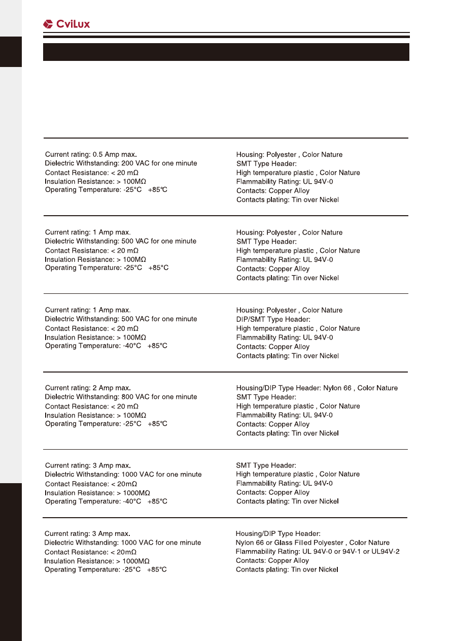
0.80mm Center spacing Wire to Board Connector                                              

Electrical-

Physical-

1.00mm Center spacing Wire to Board Connector                                              

Electrical-

Physical-

2.00mm Center spacing Wire to Board Connector                                              

Electrical-

Physical-

1.25mm and 1.50mm Center spacing Wire to Board Connector                        

Electrical-

Physical-

2.4mm Center spacing Wire to Board Connector                         

Electrical-

Physical-

2.50mm and 2.54mm Center spacing Wire to Board Connector                         

Electrical-

Physical-

~

~

~

~

~

~

wire-to-board-connectors-html.html
background image

WIRE TO BOARD CONNECTORS

77

WIRE TO BOARD

CI

 System CI - Technical Specification

3.5mm Center spacing Wire to Board Connector                                              

Electrical-

Physical-

4.00mm Center spacing Wire to Board Connector                                              

Electrical-

Physical-

Phosphor Bronze, with Tin plated

Electrical-

Physical-

3.96mm Center spacing Wire to Board Connector        

~

~

-35°C  +105°C

~

wire-to-board-connectors-html.html
background image

WIRE TO BOARD CONNECTORS

78

CI

WIRE TO BOARD

CI20 Series 0.60mm(.024") Wire to Board Housing & SMT Headers

Fixed tabs provide PCB hold-down

Locking slots provide secure mating

Insulator: High temperature plastic UL 94V-0, Color Black

Applicable Wire: AWG #34 (Insulation O.D.:  0.32±0.02mm)

   Ordering Code

③ ④ ⑤ ⑥ ⑦

C I 2 0

0 6

S

2

0 0 0

-

NH

C I 2 0

0 6

M

2

H

R

0

-

NH

Series No.

No. of Circuits: 6, 8, 10

S = Housing

Plating Code:

    2 = Gold flash over Nickel 


Other Options: 000 = Standard

Process: 

-NH = For Halogen-Free

Series No.

No. of Circuits: 6, 8, 10

M = SMT Type

Plating Code: 2 = Gold   

flash over Nickel

Type: H = Side Entry

Packing Options: 

R = Tape & Ree

 Other Options: 

0 = Standard

Process: 

-NH = For 

Lead Free IR process 

and Halogen-Free

wire-to-board-connectors-html.html
background image

WIRE TO BOARD CONNECTORS

79

WIRE TO BOARD

CI

 CI18 Series 0.80mm(.031") Wire to Board Housing & SMT Headers  

Fixed tabs provide PCB hold-down

Insulator: High temperature plastic UL 94V-0, Color Nature

Housing: High temperature plastic UL 94V-0, Color Nature

   Ordering Code

③ ④ ⑤ ⑥

C I 1 8

1 5

S

2

0 0 0

-

NH

C I 1 8

1 5

M

2

H

R

0

-

NH

Series No.

No. of Circuits: 02 to 15

S = Housing

Plating Code:

1 = Matte  Tin over Nickel

     2 = Gold flash over Nickel

Other Options: 000 = AWG #32(Standard)

00A = AWG #36

-NH = For Halogen-Free 


Series No.

No. of Circuits: 02 to 15

M = SMT Type

Plating Code: 1 = Matte Tin plated over Nickel  

                       2 = Gold flash over Nickel

Type:  V = Top Entry ;  H = Side Entry

Packing Options: R = Tape & Reel

 Other Options: 0 = Standard

Process: 

-NH = For Lead Free IR process and 

Halogen-Free

CI18**S200*-NH

CI18**M2HR0-NH

CI18**M2VR0-NH

wire-to-board-connectors-html.html
background image

WIRE TO BOARD CONNECTORS

80

CI

WIRE TO BOARD

 CI11 Series 1.00mm(.039") Single Row Wire to Board Housing & Terminal

Insulator: Polyester UL 94V-0, Color Nature

Terminal: Tin plated, Phosphor Bronze

Mate with CI11 headers

Compact design

Protrusions design for easy pull out

   Ordering Code

③ ④

C  I 1 1

1 5

S

0 0 0

0

-

NH

C I 1 1

T 0 1

1

P

P 0

Series No.

No. of Circuits: 02 to 15,  

     18, 20, 26

S = Housing

 000 = With Protrusions

N00 = Without 

Protrusion  


Other Options: 0 = 

Standard

    *Special options consult  

manufacturer

Process:


-NH = For 

Halogen-Free

Series No.

Type: T01 = 

AWG #28 ~ #32

Plating Code:

     1 = Tin over Nickel

Material:

     P = Phosphor Bronze

Other Options: P0 =   

Standard

wire-to-board-connectors-html.html
background image

WIRE TO BOARD CONNECTORS

81

WIRE TO BOARD

CI

 CI11 Series 1.00mm(.039") Single Row Wire to Board SMT Headers

Polarization and Low-profile

Locking slots provide secure mating 

Fixed tabs provide PCB hold-down 

Mate with CI11 housing

With Tin plated SMT type contact

Ordering Code

C  I  1  1  1 5 

M

1

V

R 0

-

NH

Series No.

No. of Cirsuits:

02 to 15, 18, 20, 26

M = SMT Type

Plating Code: 1 = Matte Tin over  

Nickel

Type: V = Top Entry

               H = Side Entry

Packing Options: 

     R0 = Tape & Reel

(Top entry type with pick & place 

pad)

     T0 = Tube


Process: 

-LF = For Lead Free 

soldering  process

-NH = For Lead Free 

soldering process 

and Halogen-Free

Top Entry

11.0(.433)

15

13

14

13.0(.512)

14.0(.551)

12.0(.472)

4

12

11

10

9

7

8

5

6

2

3

Circuits

5.0(.197)

3.0(.118)

7.0(.276)

8.0(.315)

9.0(.354)

10.0(.394)

4.0(.157)

5.0(.197)

6.0(.236)

6.0(.236)

1.0(.039)

2.0(.079)

A

Dimension

4.0(.157)

B

TYP.

.039

1.0

B
A

.1

14

2.

9

1.2±0.1

.047±.004

0.7±0.05

.028±.004

1.8±0

.1

.071±.0

04

A±0.1

1.0±0.05

.039±.002TYP.

0.2±0

.1

.008±.0

04

.219±.0

04

5.55±0.

1

.157±.0

04

4.

0±0

.1

TYP.

0.6±0.05

.024±.002

0.8

.031

.1

67

4.2

5

.0

85

2.

16

.1

16

2.

95

0.7±0.05

.028±.004

PICK 

 PLACE PAD

0.8

.031

4.

2±0

.1

.165±.0

04

2.65±0.

1

.104±.0

04

0.2±0.

1

.008±.0

04

1.8±0

.1

.071±.0

04

1.2±0.1

.047±.004

A±0.1

TYP.

TYP.

0.6±0.05

.024±.002

1.0±0.05

.039±.002

.18

9

4.

8

.1

69

4.

3

.189

4.8

.1

14

2.

9

.157

4.0

.039

B
A

1.0 TYP.

14.0(.551)

13.0(.512)

12.0(.472)

11.0(.433)

7.0(.276)

10.0(.394)

9.0(.354)

8.0(.315)

17.0(.669)

16.0(.630)

15.0(.591)

2.

16

.0

85

1ST Circuits Position

1ST Circuits Position

0.1

0.1

22.0(.866)

19.0(.748)

20

20.0(.787)

17.0(.669)

18

28.0(1.102)

25.0(.984)

26

Side Entry

wire-to-board-connectors-html.html
background image

WIRE TO BOARD CONNECTORS

82

CI

WIRE TO BOARD

 CI11 Series 1.00mm(.039") Dual Row Wire to Board Housing & Terminal

Insulator: Polyester UL 94V-0, Color Nature

Terminal: Tin plated, Phosphor Bronze

Mate with CI11 headers

Compact design

Protrusions design for easy pull out

   Ordering Code

③ ④

③ ④

C  I 1 1

5 0

S

D

0 0 0

-

NH

C  I 1 1

T01

1

P

P H

Series No.

No. of Circuits: 14, 16, 20, 30, 40, 50

S = Housing

D=Dual Row Type

Other Options: 000 = Standard

    *Special options consult  manufacturer

Process: 

-NH = For Halogen-Free

Series No.

Type:T01= AWG #28~#32

Plating Code: 1= Tin over Nickel

Material: P=Phosphor Bronze

Other Option:

     PH= Low Single contact force

1.5

5

.0

61

1.1

5

.04

5

1.2

.047

1.5

.059

SEC.: B-B

SEC.: A-A

B

B

A

A

1.35
.053

3.

9

.15

4

1.

6

.06

3

0.

75

.0

30

1.9

5

.0

76

0.3

.012

1.

35

.05

3

1.

5

.05

9

1.5 TYP.

.059

4.0 TYP.

.157

7.

7

.30

3

3.

0

.1

18

0.

5

.0

20

0.12t

.005

0.85 TYP.2

1.6

.033

.063

.07

5

1.

9

0.7

.028

0.

5

.0

20

.1

46

3.

7

1.15

1.525

.060

.16

5

4.

2

5.

0

.19

7

.045

.165

4.2

C = A + 2.2

A = 1.0 x No. of Spaces

B = A + 4.0

4.

9

.1

93

B

TYP.

1.0

.039

A

C

Range

Wire

#28~#32

AWG

Diameter

Insulation

(.016~.031)

0.4~0.8(mm)

Reel Q'ty

16,000 PCS

wire-to-board-connectors-html.html
background image

WIRE TO BOARD CONNECTORS

83

WIRE TO BOARD

CI

 CI11 Series 1.00mm(.039") Dual Row Wire to Board SMT Headers

Polarization and Low-profile

Locking slots provide secure mating 

Fixed tabs provide PCB hold-down 

With Tin plated SMT type contact

Ordering Code

C  I  1  1  5 0

M

2

V

D

0

-

R0

-


NH

Series No.

No. of Cirsuits:

Top Entry: 10,14,16,20,30,40,50

Side Entry: 12,16,18,20,30,40,50

M = SMT Type

Plating Code:

     2 = Gold flash over Nickel

Type: V = Top Entry

               H = Side Entry

D = Dual Row type

 Pegs Options:

    Top Entry: 0 = With Pegs(Standard)

                     1 = Without Peg

    Side Entry: 0 = Standard

Packing Options: 

     R0 = Tape & Reel

     T0 = Tube

Process: 

-NH = For Lead Free IR 

process and 

Halogen-Free

Top Entry

Side Entry

wire-to-board-connectors-html.html
background image

WIRE TO BOARD CONNECTORS

84

CI

WIRE TO BOARD

 CI16 Series 1.00mm(.039") Wire to Board Connectors Housing & Terminal

Mate with CI16 header

Can be used with CI16 crimp clip terminal

Insulator: Nylon 66 UL 94V-0, Color Nature

   Ordering Code

③ ④

③ ④

C  I 1 6

2 0

S

L

0 0 0

-

NH

C  I 1 6

T01

1

P

E 0

Series No.

No. of Circuits: 02 to 20

S = Connector housing

L=With Locking Latch

Other Options: 000 = Standard

                             00A=Type 1    

Process: 

-NH = For Halogen-Free

Series No.

Type:T01= AWG #28~#32

Plating Code: 1= Tin over Nickel

Material: P=Phosphor Bronze

Other Option: E0=Standard

wire-to-board-connectors-html.html
background image

WIRE TO BOARD CONNECTORS

85

WIRE TO BOARD

CI

 CI16 Series 1.00mm(.039") Wire to Board Connectors SMT Headers

Fixed tabs provide PCB hold-down

Mate with CI16 housing

Insulator:  High temperature plastic UL 94V-0, Color Nature

Terminal: Tin plated Phosphor Bronze

Ordering Code

C  I  1  6  2 0

M

1

V

R

0

-

NH


Series No.

No. of Circuits: 02 to 20

M = SMT Type

 Plating Code: 1 = Matte Tin over Nickel

Type: V = Top Entry

              H = Side Entry

Packing Options: R = Tape & Reel

Other Option: 0 = Standard 

                           A = Type 1

Process: 

-NH = For Lead Free IR Process and 

Halogen-Free

wire-to-board-connectors-html.html
background image

WIRE TO BOARD CONNECTORS

86

CI

WIRE TO BOARD

 CI14 Series 1.00mm(.039") Wire to Board Connectors Housing & Terminal

Mate with CI14 Header

Can be used with CI14 crimp clip terminal

Insulator: Glass filled polyester UL 94V-0, Color Nature

Terminal: Tin plated Phosphor Bronze

   Ordering Code

③ ④

C  I 1 4

2 0

S

0 0 0 A

-

NH

C  I 1 4

T01

1

P

E 0

Series No.

No. of Circuits: 02 to 20

S = Housing

000A = Without Locking Latch

     L000 = With Locking Latch

Process: 

-NH = Halogen-Free    

Series No.

Type:T01= AWG #28~#32

Plating Code: 1= Tin plated

Material: P=Phosphor Bronze

Other Option: E0=Standard

wire-to-board-connectors-html.html
background image

WIRE TO BOARD CONNECTORS

87

WIRE TO BOARD

CI

CI14 Series 1.00mm(.039") Wire to Board SMT Side Entry Headers

Fixed tabs provide PCB hold-down

Mate with CI14 Housing

Insulator : High temperature plastic UL 94V-0, Color Nature

wire-to-board-connectors-html.html
background image

WIRE TO BOARD CONNECTORS

88

CI

WIRE TO BOARD

 CI14 Series 1.00mm(.039") Wire to Board SMT Side / Top Entry Headers

Fixed tabs provide PCB hold-down

Mating with CI14 Housing

Insulator: High temperature plastic UL 94V-0, color Nature

Ordering Code

C I 1 4 

2  0

1

H

R C

-

NH

NH

Series No.

No. of Circuits:

(Available:  R0:  2~20                                                                                             

  RC: 2~12

    RL:  2~20                                                                                             

  RE: 2~12)

M = SMT Type

Plating Code: 1 = Matte Tin over Nickel

Type: H = Side Entry 

Other Options:

R0 = Normal Type with Reel Packing ( H Type, 02 to 20 )

RL = Normal Lock Type with Reel Packing ( H Type, 02 to 20) 

RC = Short Type with Reel Packing ( H Type, 02 to 12 )

RE = Short Lock Type with Reel Packing ( H Type, 02 to 12 )

⑦ 

Process

-NH = For Lead Free IR process and Halogen-Free

WIRE  

TO  BOARD

wire-to-board-connectors-html.html
background image

WIRE TO BOARD CONNECTORS

89

WIRE TO BOARD

CI

WIRE  

TO  BOARD

 CI14 Series 1.00mm(.039") Wire to Board SMT Side / Top Entry Headers

Fixed tabs provide PCB hold-down

Mating with CI14 Housing

Insulator: High temperature plastic UL 94V-0, color Nature

Ordering Code

C I 1 4 

1  2

1

V

L 0

-

NH

NH

Series No.

No. of Circuits: 2~12

M = SMT Type

Plating Code: 1 = Matte Tin over Nickel

Type: V = Top Entry

Other Options: 

L0 = Locking Type with Reel Packing

⑦ 

Process

-NH = For Lead Free IR process and Halogen-Free

wire-to-board-connectors-html.html
background image

WIRE TO BOARD CONNECTORS

90

CI

WIRE TO BOARD

 CI14 Series 1.00mm(.039") Wire to Board Housing & SMT Side Entry Header

Can be used CI14 crimp clip terminal

Insulator: High temperature plastic UL 94V-0, Color Nature

Inuslator: Nylon 66 UL 94V-0, Color Nature

With locking latch provide secure mating

   Ordering Code

③ ④

③ ④ ⑤ ⑥

C  I 1 4

0 3

S

L

0 0 C

-

NH

C  I 1 4

0 3

M

1

H

R       

I

-

NH

Series No.

No. of Circuits: 03 to 20

S= Housing

L=With Locking Latch

Other Option: 00C = Latch Type 2

Process: 

-NH = Halogen-Free

Series No.

No. of Circuits: 03 to 20

M = SMT Type

Plating Code: 1 = Matte Tin over Nickel

Type: H = Side Entry

Packing Options: R = Tape & Reel

Other Options: I = Dual Latch Type

Process: 

-NH = For Lead Free IR process and 

Halogen-Free

wire-to-board-connectors-html.html
background image

WIRE TO BOARD CONNECTORS

91

WIRE TO BOARD

CI

 CI63 Series 1.20mm(.048") Wire to Board Housing / Terminal

Mate with CI63 Header

Can be used with CI63 crimp clip terminal

Insulation: High temperature plastic UL 94V-0, Color Black

   Ordering Code

③ ④

C  I 6 3

0 7

S

0    0   0   0 

C  I 6 3

T 0 1

2

P

P  0       

Series No.

No. of Circuits: 02 to 07

S = Housing

Other Options: 0000 = Standard

Series No.

Type: T01=AWG #28~ #30

Plating : 

     2 = Gold Flash plated over Nickel

Material : P=Phosphor Bronze

Option : P0 =Standard

P/N

CI63**S0000

P/N

CI63T012PP0

wire-to-board-connectors-html.html
background image

WIRE TO BOARD CONNECTORS

92

CI

WIRE TO BOARD

 CI63 Series 1.20mm(.048") Wire to Board SMT Headers

Mate with CI63 Housing

Insulation: High temperature plastic UL 94V-0,

Color Black

   Ordering Code

C  I 6 3

1 0

M

2

V

R       

0

-

NH

Series No.

No. of Circuits: 2 to 8,10

Solder Type: M = SMT

Plating Code: 2 = Gold plated over Nickel

Type: V = Vertical Type

Packing Options: R = Tape & Reel Packing

Other Option: 0 = Standard

⑧ 

Process: 

-NH = For Lead Free IR process and 

Halogen-Free

wire-to-board-connectors-html.html
background image

WIRE TO BOARD CONNECTORS

93

WIRE TO BOARD

CI

 CI40 Series 1.25mm(.049") Wire to Board Housing & Terminal & SMT Header

Locking slots provide secure mating

Fixed tab PCB hold-down and strain-relief for SMT tail

Insulator: High temperture plastic UL 94V-0, Color Nature 

Ordering Code

C I 4 0 

1  5

1

V

R 0

-

NH

NH

Series No.

No. of Circuits: 02 to 15

 Contact Type : M = SMT

Plating Code: 

    1 = Matte Tin plated over Nickel

Tail Style: H=Side entry

                     V=Vertical

Option : R0=Tape & Reel Packing

Process: 

-NH = For Lead Free IR Process and 

Halogen-Free

wire-to-board-connectors-html.html
background image

WIRE TO BOARD CONNECTORS

94

CI

WIRE TO BOARD

 CI40 Series 1.25mm(.049") Wire to Board Housing & Terminal & SMT Header

Locking latch provide secure mating

Insulation: Nylon66 UL 94V-0,Color Nature 

With Gold flash SMT type contact

   Ordering Code

③ ④

C  I 4 0

0 2

S

L   0   0   0 

-

N H

C  I 4 0 T


0


1 1

P

P  0       

Series No.

No. of Circuits: 

S =Connector Housing

Other Options: L000 = Nature (Standard)

Process: 

-NH = Halogen-Free

Series No.

Type: T01=AWG #26~ #30

Plating Code: 

     1=Tin over Nickel

Material : P=Phosphor Bronze

Other


Options : P0 =Standard

wire-to-board-connectors-html.html
background image

WIRE TO BOARD CONNECTORS

95

WIRE TO BOARD

CI

 CI42 Series 1.25mm(.049") Wire to Board Housing & Terminal

Mate with CI42 Header

Can be used with CI42 Crimp clip terminal

Insulation: Glass filled polyester UL 94V-0,Color Nature 

   Ordering Code

③ ④

③ ④

C  I 4 2

1 0

S

L

0   0   0

C  I 4 2

T 0 1

1

P

P  0

Series No.

No. of Circuits: 02 to 20

S= Housing

L=With Latch

Other Options: 000=Standard

Series No.

Type: T01=AWG #28~ #32

Plating Code: 

     1 = Tin over Nickel

Material : P=Phosphor Bronze

Other


Options : P0 =Standard

wire-to-board-connectors-html.html
background image

WIRE TO BOARD CONNECTORS

96

CI

WIRE TO BOARD

 CI42 Series 1.25mm(.049") Wire to Board SMT Header

Locking ramps provide secure mating

Fixed tab PCB hold-down and strain-relief for SMT tail

Insulator: High temperature plastic UL 94V-0, Color Nature

With Gold flash SMT type contact

   Ordering Code

④ ⑤ ⑥ ⑦

C  I 4 2

1 2

M

2

H

R   P     

-

NH

Series No.

No. of Circuits: 02 to 12

M = SMT Type

Plating Code:

2 = Gold flash over Nickel

Type: H = Side Entry

Packing Options: 

R = Tape & Reel

Other Options:

0 = Without Mylar

P = With Mylar

D = Middle mount type, Without Mylar

A = Middle mount type, With Mylar

Process: 

-NH = For Lead Free IR process and Halogen-Free

CI42**M*H*0/P-NH

P/N

CI42**M*H*A/D-NH

P/N

wire-to-board-connectors-html.html
background image

WIRE TO BOARD CONNECTORS

97

WIRE TO BOARD

CI

 CI43 Series 1.25mm(.049") Wire to Board Housing & Terminal & SMT Header

2.03mm above the board

Copper alloy dual contacts

Insulation: High temperature plastic UL 94V-0, Color Black

With metal fixed tabs to secure connector in place

C

CI43**S0000

P/N

CI43T011PE0

P/N

CI43**M1HR0-NH

P/N

A = 1.25 * No. of Spaces
B = A + 4.75
C = A + 2.55

#28~#32

Range

Reel Q'ty

20,000 PCS.

(.039)

Diameter

Insulation

AWG

Wire

1.0

MAX.

SEC.: A-A

SEC.: B-B

.037

XX

1.25

A

C

B

1.37

5.

9

1.95

2P~6P

7P~30P

.054

.077

.049

.23

2

4.5

0.1

1.

05

0.

8

0.95

0.

55

2.

3

0.

92

5.

05

1.2

1.

2

1.6

1.

4

A

A

B

B

.177

.004

.047

.063

0.15
.006

.02

2

.03

6

.19

9

.09

1

.04

1

.03

1

.04

7

.05

5

Solder Pad Pattern

t

   Ordering Code

③ ④ ⑤ ⑥

C  I 4 3

3 0

S

0  0  0  0

C  I 4 3

1 2

M

1

H

R        0

-

NH

Series No.

No. of Circuits: 02 to 15,20,25,30

 S = Housing

Other Options:

     0000 = Standard

Series No.

No. of Circuits: 02 to 12

 M = SMT Type

1 = Matte Tin plated over Nickel

     2 = Gold flash over Nickel

Type: H=Side Entry

Packing Options: 

R = Tape & Reel

Other Options:

     0 = Standard 

Process: 

-NH = For Lead Free 

soldering 

process and 

Halogen-Free

wire-to-board-connectors-html.html
background image

WIRE TO BOARD CONNECTORS

98

CI

WIRE TO BOARD

 CI44 Series 1.25mm(.049") Wire to Board Connectors Housing & Terminal

Latch housing secure terminal in housing 

    and provides extra terminal retention 

Terminal accommodated AWG #28 ~ #32

Insulator: Polyester UL 94V-0, Color Nature

Terminal: Tin plated,  Phosphor Bronze

Mate with CI44 header

   Ordering Code

④ ⑤

③ ④

C  I 4 4

1 5

S 0 0

0

0

 -

NH

C  I 4 4

T01

1

P

P  0       

Series No.

No. of Circuits: 02 to 15

S00= Housing

Color: 0 = Color Nature

Other Options: 0 = Standard

Process: 

-NH = Halogen-Free

Series No.

Type: T01 = AWG #28 ~ #32

Plating Code: 1 = Tin over Nickel

Material: P = Phosphor Bronze

Other Options: P0 = Standard

wire-to-board-connectors-html.html
background image

WIRE TO BOARD CONNECTORS

99

WIRE TO BOARD

CI

Ordering Code

C I 4 4 

1  5

1

V

0 0

-

NH

NH

Series No.

No. of Circuits: 02 to 15

P = DIP Type

Plating Code:

     1 = Matte Tin over Nickel plated

Type: V = Top Entry

              H = Side Entry

Other Options

:

00 = Standard (Tube packing)

R0 = Tape & Reel (Without Pick & Place Pad)  

RP = Tape & Reel (With Pick & Place Pad)

Process: 

-NH = For Lead Free soldering process and 

Halogen-Free

    *Special options consult manufacturer

 CI44 Series 1.25mm(.049") Wire to Board Connectors DIP Headers

Polarization and Low-profile

Locking slots provide secure mating

Mate with CI44 housing

Insulator: High temperature plastic UL 94V-0, Color Nature

With Tin plated DIP type contact

Straight

Right Angle

.012

.049

TYP.

.09

1

.16

5

1ST Circuit Position

.09

4

.12

6

3.

2

2.

4

4.

2

2.

3

A

C

1.25

B

TYP.

0.3

.049

TYP.

.012

.13

7

.09

4

.21

7

.091

3.

5

1ST Circuit Position

2.3

4.

2

5.

5

C

0.3

1.25

A

B

TYP.

1.25±0.05

.049±.002

A±0.1

TYP.

.020±.002

0.5±0.05

14.40(.567)

11

12.50(.492)

15.6(.614)

13.75(.541)

16.25(.640)

15.00(.591)

17.50(.689)

15

13

14

12

15.65(.616)

16.90(.665)

18.15(.715)

19.40(.764)

16.85(.663)

18.1(.713)

19.35(.762)

20.6(.811)

1.25(.049)

A

2.50(.098)

6.25(.246)

3.75(.148)

11.25(.443)

8.75(.344)

5.00(.197)

7.50(.295)

10.00(.394)

3

7

9

10

8

5

6

4

2

Circuits

3.15(.124)

4.40(.173)

5.65(.222)

6.90(.272)

8.15(.321)

9.40(.370)

10.65(.419)

11.90(.469)

13.15(.518)

5.6(.220)

6.85(.270)

8.1(.319)

9.35(.368)

10.6(.417)

11.85(.467)

13.1(.516)

14.35(.565)

Dimension

4.35(.171)

B

C

wire-to-board-connectors-html.html
background image

WIRE TO BOARD CONNECTORS

100

CI

WIRE TO BOARD

Ordering Code

C I 4 4 

1  5

1

V

 R 0

-

NH

NH

Series No.

No. of Circuits: 02 to 15

M=SMT Type

Plating Code:

     1 = Matte Tin over Nickel plated

Type: V = Top Entry

              H = Side Entry

Other Options :

     00 = Standard (Tube packing)

     R0 = Tape & Reel (Without Pick & Place Pad)

     RP = Tape & Reel (With Pick & Place Pad)

Process: 

-NH = For Lead Free soldering process 

and Halogen - Free

     * Special option consult manufaturer

 CI44 Series 1.25mm(.049") Wire to Board Connectors SMT Headers

Polarization and Low-profile

Locking slots provide secure mating

Fixed tabs provide PCB hold-down and strain-relief for SMT 

Insulator: High temperature plastic UL 94V-0 , Color Nature 

With Tin plated SMT type contact

Mate with CI44 housing

Top Entry

Side Entry

TYP.

FOR 2 Circuits

FOR 3 Circuits

.012

0.3

2.

2

.08

7

C

A

1.25

.049

TYP.

B

C = A + 1.9

.018

0.45

A = 1.25 x No. of Spaces

.18

9

.058

1.48

B = A + 6.1

4.

8

.146

3.7

1ST Circuit Position

0.

75

.03

0

2.

4

.09

4

.11

8±.0

04

.031±.002

0.8±0.05

.083±.004

2.1±0.1

TYP.

3.0±0

.1

.142±.004

3.6±0.1

#1

1.

M

in

.

.049±.002

1.25±0.05

TYP.

A±0.1

.06

3

.02

4±.0

04

0.

0.

1

FOR 2 Circuits

FOR 3 Circuits

1ST Circuit Position

TYP.

.049

1.25

.012

0.3

TYP.

B
C
A

C = A + 1.9

A = 1.25 x No. of Spaces
B = A + 6.1

.058

1.48

.02

9

0.

75

.13

2

3.

35

.09

4

2.

4

.08

7

2.

2

.16

5

4.

2

.03

9

1.

0

.031

0.8

.118±.004

3.

0.

1

0.8±0.05

.031±.002

.083±.004

2.1±0.1

TYP.

3.6±0.1

.142±.004

#1

.049±.002

1.25±0.05

TYP.

A±0.1

.02

4±.0

04

1.

M

in

.

.06

3

0.

0.

1

Pick   Place Pad

0~0

.1

0~

.0

04

0~0

.1

0~

.0

04

0.1

0.1

0.

5

.02

0

PIN MARK

Pick   Place Pad

Solder Pad Pattern

Solder Pad Pattern

wire-to-board-connectors-html.html
background image

WIRE TO BOARD CONNECTORS

101

WIRE TO BOARD

CI

 CI45 Series 1.25mm(.049") Wire to Board Housing & SMT Headers

With locking latch provide secure mating

Mate with CI45 Header

Mate with CI14 crimp clip terminal


(P/N: CI14T011PE0)

   Ordering Code

③ ④

C  I 4 5

1 9

S

L  0 0 0 0

-

NH

C I 4 5

1  9 

M   1

H

R 0

-

NH

Series No.

No. of Circuits:19

 S = Housing

 L= With Locking Latch   

 Other Option: 000=Standard

Process: 

-NH= Halogen- Free

Series No.

No. of Circuits: 19

 M = SMT Type

Plating Code: 1 = Matte Tin plated over Nickel

Type: H=Side Entry

Packing Options: R0 = Tape & Reel

Process: 

-NH = For Lead Free IR Process and Halogen-Free  

wire-to-board-connectors-html.html
background image

WIRE TO BOARD CONNECTORS

102

CI

WIRE TO BOARD

   Ordering Code

③ ④

C  I 4 6

2 0

S

L

 0 0 0 -

C I 4 6

T  0  1 

1

 P

E 0

Series No.

No. of Circuits: 02 to 20

S = Housing

L = With Locking Latch 

Other Options: 000 = Standard

Series No.

Type: T01 = AWG #26 ~ #32

Plating Code: 1 = Tin over Nickel

Material: P = Phosphor Bronze

Other Options: E0 = Standard

 CI46 Series 1.25mm(.049") Wire to Board Connectors Housing & Terminal

With locking latch provide secure mating

Mate with CI46 Header

Can be used with CI46 Crimp Clip Terminal

Insulator: Nylon 66 UL 94V-0, Color Nature

wire-to-board-connectors-html.html
background image

WIRE TO BOARD CONNECTORS

103

WIRE TO BOARD

CI

 CI46 Series 1.25mm(.049") Wire to Board Connectors SMT Headers

With locks provide secure mating 

Fixed tabs provide PCB hold-down 

Mate with CI46 Housing

Insulator: High temperature plastic UL 94V-0, Color Nature

Top Entry

Side Entry

Ordering Code

C I 4 6 

2 0

1

V

R

0

-

NH

Series No.

No. of Circuits: 02 to 20

M = SMT Type

Plating Code :

     1= Matte Tin plated over Nickel

Type: V =Top Entry

               H=Side Entry

Packing Options: 

     R0 = Tape & Reel

Other Options:

     0 = Standard

Process: -NH = For Lead Free soldering process and 

Halogen-Free

wire-to-board-connectors-html.html
background image

WIRE TO BOARD CONNECTORS

104

CI

WIRE TO BOARD

 ClDL Series 1.25mm(.049'') Wire to Board Connectors

Can be used with CI14 crimp clip terminal

Insulator: Nylon 66 UL 94V-0, Color Nature

Insulator: High temperature UL 94V-0 , Color Nature

   Ordering Code

C  I D L

0 3

S

L 0 0 0

-

N H

C I D L 

0 3

M   1

H

 R 0

-

N H 

Series No.

No. of Circuits: 03 

S = Connector Housing

Other option: L000=With Locking Latch

Other Option: -NH= Halogen-Free

Series No.

No. of Circuits: 03 

M=SMT type Header

Plating: 1=Matte Tin over Nickel

Type: H = Side Entry Type

Option : R0 = Tape & Reel Packing

Process: 

 -NH= For Lead Free IR Processes and 

Halogen-Free

wire-to-board-connectors-html.html
background image

WIRE TO BOARD CONNECTORS

105

WIRE TO BOARD

CI

 ClDM Series 1.25mm(.049'') Wire to Board Connectors

Fixed tabs provide PCB hold-down

Insulator: High temperatrue plastic UL 94V-0 , Color Nature

Ordering Code

C I D M

0 3

1

V

R

0

-

NH

Series No.

No. of Circuits: 02~15

M= SMT Type Header 

Plating Code: 1= Matte Tin over Nickel

Type : V = Vertical

H = Right angle 

Packing Option : R = Tape & Reel Packing

Option : 0 = Nature Color

                  1 = Black

Process:


    -NH= For Lead Free IR Processes and Halogen-Free

wire-to-board-connectors-html.html
background image

WIRE TO BOARD CONNECTORS

106

CI

WIRE TO BOARD

   Ordering Code

C  I 1 5

1 5

S

0  0  0  0

-

C I 1 5

T  0  1 

1

 P

E 0

Series No.

No. of Circuits: 02 to 15

S = Housing

Other Options: 0000 = Standard

Series No.

Type: T01 = AWG #26 ~ #32

Plating Code: 1 = Tin over Nickel

Material: P = Phosphor Bronze

Other Options: E0 = Standard

 CI15 Series 1.50mm(.059") Wire to Board Connectors Housing & Terminal

Terminal accommodated AWG #26 ~ #32

Insulator: Nylon 66 UL 94V-0, Color Nature

Terminal: Tin plated, Phosphor Bronze

Mate with CI15 Header

wire-to-board-connectors-html.html
background image

WIRE TO BOARD CONNECTORS

107

WIRE TO BOARD

CI

 CI15 Series 1.50mm(.059") Wire to Board Connectors DIP Headers

Polarization and Low-profile

Locking slots provide secure mating

Insulator: High temperature plastic UL 94V-0, Color Nature

With Tin plated DIP type contact

Mate with CI15 Housing

Ordering Code

C I 1 5 

1 5

1

V

K

0

-

N H

Series No.

No. of Circuits: 02 to15

P = DIP Type

Plating Code :

     1= Matte Tin plated over Nickel

Type: V =Straight

               H=Right Angle

K = With Pin Kinked

Other Options: 0 = Standard

Process: -NH = For Lead Free soldering process 

and Halogen-Free


Straight

Right Angle

.028±.004

0.7±0.1 TYP.

10.5(.413)

9.6(.378)

7.5(.295)

6

15.0(.591)

13.5(.531)

12.0(.472)

10.5(.413)

9.0(.354)

16.5(.650)

18.0(.709)

12

13

7

9

8

11

10

17.1(.673)

15.6(.614)

11.1(.437)

14.1(.555)

12.6(.496)

18.6(.732)

20.1(.791)

19.5(.768)

21.0(.827)

18.0(.709)

16.5(.650)

15.0(.591)

13.5(.531)

12.0(.472)

1.5(.059)

6.0(.236)

4.5(.177)

3.0(.118)

Circuits

2

3

5

4

A

TYP.

1.5±0.05

.059±.002

C

3.6(.142)

8.1(.319)

6.6(.260)

5.1(.201)

Dimension

4.5(.177)

9.0(.354)

7.5(.295)

6.0(.236)

B

15

14

19.5(.768)

21.0(.827)

22.5(.886)

24.0(.945)

23.1(.909)

21.6(.850)

0.5

.020

2.

8

TYP.

.11

0

.11

0

2.

8

B

1.5

.059

TYP.

A

4.

5

.17

7

0.

9

.03

5

1ST Circuits Position

C

1.3

.138

3.5

.14

6

3.

7

.11

0

2.

8

C

2.

8

.11

0

1ST Circuits Position

A

.03

5

0.

9

1.5

.059

TYP.

B

TYP.

.059

0.5

4.75

.187

2.

2

0.78
.031

.051

.88

6

2.

2

.88

6

0.79
.311

wire-to-board-connectors-html.html
background image

WIRE TO BOARD CONNECTORS

108

CI

WIRE TO BOARD

 CI15 Series 1.50mm(.059") Wire to Board Connectors SMT Headers

Polarization and Low-profile

Locking slots provide secure mating

Fixed tabs provide PCB hold-down and strain-relief for SMT tails

Insulator: High temperature plastic UL 94V-0, Color Nature

With Tin plated SMT type contact

Mate with CI15 Housing

Top Entry

Side Entry

C = A + 2.1

B = A + 4.5

A = 1.5 x No. of Spaces

C

TYP.

1.5

0.5 TYP.

B

A

4.

0.

1

.16

9±.0

04

.11

0

2.

8

A±0.1

1.5±0.05

.059±.002

1.

0.0

5

.05

5±.0

02

0.7±0.1 TYP.

.028±.004

TYP.

1.4±0.05

.055±.002

1.1±0.1

.043±.004

1.

5

.05

9

1.3

.051

5.

0

.20

0

1.

0.

1

.07

5±.0

04

3.

75

0~0

.1

.059

.020

.14

8

0~

.0

04

7.

(R

ef

.)

0.1

1ST Circuits Position

C

0.5

.020

B

A

C = A + 2.1

1.5 TYP.

A = 1.5 * No.of Spaces

B = A + 4.5

5.

0

.19

7

2.

8

.11

0

0.

9

.03

5

.059

.060±.002

1.5±0.05

TYP.

0.10

0~0

.1

0~

.0

04

5.

05

.19

9

.05

7

1.

46

2.

0.

1

.09

0±.0

04

1.5±0.1 TYP.2

.060±.004

1.3±0.1

.051±.004

2.

35

3.7

.145

.09

3

Pick 

&

 Place PAD

3.

65

 M

in

.

.14

3

0.7 Min.

.028

TYP.

1.

0.

1

.05

5±.0

04

0.

0.

1

.02

4±.0

04

A±0.1

Top

Ordering Code

C I 1 5 

1 5

1

V

R

0

-

N H

Series No.

No. of Circuits: 02 to 15

M = SMT Type

Plating Code: 1 = Matte Tin over Nickel

Type: V = Top Entry

               H= Side Entry

Packing Options:

     R = Tape & Reel

     T = Tube

Other Options: 0 = Standard

*Special options consult manufacturer

Process: 

-NH = For Lead Free soldering process and 

Halogen-Free

wire-to-board-connectors-html.html
background image

WIRE TO BOARD CONNECTORS

109

WIRE TO BOARD

CI

   Ordering Code

⑥ ⑦

C  I 1 5

0 7

S

L 0 0 0

C I 1 5

0  7

M   1

H

T

L

-

N H

Series No.

No. of Circuits: 07

S = Housing

Other Options :

     L000= Standard

Series No.

No. of Circuits: 07

M = SMT Type

Plating Code: 1 = Matte Tin plated over Nickel

Type: H = Right Angle

Packing Options: T = Tube (Standard) R = Tape & Reel

L = Latch Type

Process: 

-NH = For Lead Free IR Process and Halogen-Free

 CI15 Series 1.50mm(.059") Wire to Board Latch Type Housing & SMT Header

Fixed tabs provide PCB hold-down

Insulator: High temperature UL 94V-0, Color Nature

Housing: Nylon 66 UL 94V-0, Color Nature

Housing mate with CI15 Terminal (P/N: CI15T011PE0)

7

9.0

4

6

5

3

2

.01

2

0.

3

.18

1

4.

6

1

11.0

.23

6

.120

3.05

.083

2.1

6.

0

.059

1.5 TYP.

.10

4

2.

65

1ST Circuit

12.0

2.

8

11.1

.437

A

.11

0

5.

0

.19

7

1.

5

.05

9

0.5

.020

A

TYP.

.059

1.5

TYP.

9.0

.354

13.5

.531

1.

0.0

5

.05

5±.0

02

1.1±0.1

.043±.004

1.5±0.05

.059±.002

0~

.0

04

0~0

.1

0

.14

8

3.

75

1.4±0.05

.055±.002

0.10

TYP.

9.0±0.05

.354±.002

0.7±0.10 TYP.

.028±.004

PCB EDGE

4.

0.1

0

.16

9±.0

04

1.

0.

1

.07

5±.0

04

1ST Circuit

.354

.433

.472

wire-to-board-connectors-html.html
background image

WIRE TO BOARD CONNECTORS

110

CI

WIRE TO BOARD

   Ordering Code

③ ④

    ⑤

  ⑥

C  I 1 9

0 8

S

L   0 0 0

 -

N  H

C  I  1  9

T  0  1  1

P

E 0

Series No.

No. of Circuits: 02 to 15

     (Available: 02 to 05, 08) 

S = Housing

L = With Ramp

Other Options: 000 = Standard

Process: 

-NH = Halogen-Free

Series No.

Type: T01 = AWG #24 ~ #30

Plating Code: 1 = Tin over Nickel

Material: P = Phosphor Bronze

Other Option: E0 = Standard

 CI19 Series 1.50mm(.059") Wire to Board Connectors Housing & Terminal

Mate with CI19 Header

Can be used with CI19 Crimp Clip Terminal

Insulator: High temperature plastic UL 94V-0, Color Nature

wire-to-board-connectors-html.html
background image

WIRE TO BOARD CONNECTORS

111

WIRE TO BOARD

CI

 CI19 Series 1.50mm(.059") Wire to Board Connectors SMT Headers

Insulator: High temperature plastic UL 94V-0, Color Black

Top Entry

Side Entry

A

No. of Spaces

No. of Spaces

&

Ordering Code

C I  1  9 

2 0

1

H

R  0

-

N H

NH

Series No.

No. of Circuits: 02 to 20

M = SMT Type

Plating Code:

    1 = Matte Tin over Nickel

    2 = Gold flash over Nickel

Type: V = Top Entry

              H = Side Entry

Packing Options: 

     R0 = Tape & Reel

Process: 

-NH = For Lead Free IR Process and 

Halogen-Free

wire-to-board-connectors-html.html
background image

WIRE TO BOARD CONNECTORS

112

CI

WIRE TO BOARD

   Ordering Code


C  I 8  7

1 0

S

0 0 0 0

C  I  8  7

1 0

M

2

V

 R

0

-

N H

Series No.

No. of Circuits: 8,10

S = Housing

Other Options: 0000 = Standard

Series No.

No. of Circuits: 8,10

M = SMT Type

Plating Code:

     2 = Gold plated over Nickel

Type: V = Top Entry

Packing Options: R = Tape & Reel

Other Options: 0 = Standard

Process: 

-NH = For Lead Free IR process and Halogen-

Free

 CI87 Series 1.50mm(.059") Wire to Board Housing & Terminal & SMT Header

Locking slots provide secure mating 

Fixed tabs provide PCB hold-down and strain-relief for SMT tails

Insulator: High temperature plastic UL 94V-0, Color Black (Header)

Insulation: Nylon66 UL 94V-0, Color Nature (Housing)

wire-to-board-connectors-html.html
background image

WIRE TO BOARD CONNECTORS

113

WIRE TO BOARD

CI

   Ordering Code

C  I 0 7

0 2

S

L 0 0 0


- N H

C I 0 7

T 0 2

1

  P

E 0

Series No.

No. of Circuits: 02 

S = Housing

Other Options:

     0000 = Without Locking Latch

     L000-NH = With Locking Latch

Series No.

Type: T01 = AWG #28 ~ #30

T02 = AWG #22 ~ #26

Plating Code: 1 = Tin Plated

Material: P = Phosphor Bronze

Other Options: E0 = Standard

 CI07 Series 1.80mm(.071") Wire to Board Connectors Housing & Terminal

Mate with CI07 Header

Can be used with CI07 Crimp Clip Terminal

Insulator: Nylon66 UL 94V-0, Color Nature

CF

P/N

CI07**S0000

P/N

CI07**SL000-NH

P/N

CI07T021PE0

B

B

A

A

5.

1

.20

1

2.

55

.10

0

1.

0

.03

9

2.

2

.08

7

2.

35

.09

3

1.

5

.05

9

Ø1.5 TYP.

.059

6.2 TYP.

.276

8.

95

.35

2

3.

0

.11

8

0.

5

.02

0

0.2t

.008

0.25

.010

1.3

.051

Range

Wire

AWG #22~#26

Diameter

Insulation

(.037~.051)

0.95~1.3(mm)

Reel Q'ty

10,000 PCS

2.

0

6.

0

.23

6

.07

9

0.

3

.01

2

1.8

3.8

.150

.071

1.4

1.

5

1ST Circuits

.055

.05

9

2.65

2.35

.093

.104

1.8

.071

3.8

.150

4.

15

.16

3

2.

0

6.

0

.07

9

.23

6

4.

95

6.

6

.19

5

.26

0

2.35
.093

1.65
.065

1.3

.051

AWG #28~#30

(.035~.037)

0.88~0.95(mm)

10,000 PCS

1.2

1.

2

.04

7

.047

1.8

.071

1.

9

.07

5

SEC. A-A

SEC. B-B

P/N: CI07T021PE0

P/N: CI07T011PE0

SEC. B-B

SEC. A-A

1.7

.067

1.

65

.06

5

2.

5

.09

8

2.6

.102

wire-to-board-connectors-html.html
background image

WIRE TO BOARD CONNECTORS

114

CI

WIRE TO BOARD

 CI07 Series 1.80mm(.071") Wire to Board Connectors SMT Headers

Fixed tabs provide PCB hold-down

Mate with CI07 Housing

Insulator: High temperature plastic UL 94V-0, Color Nature

Ordering Code

C I 0 7 

0  2

1

H

R

L

-

N H

Series No.

No. of Circuits: 02

M = SMT Type

Plating Code:

     1 = Matte Tin over Nickel

Type: H = Side Entry

V = Top Entry

Packing Options: R = Tape & Reel

Other Options:

     L = With Locking Ramp

Process: 

-NH = For Lead Free IR process and Halogen-

Free

wire-to-board-connectors-html.html
background image

WIRE TO BOARD CONNECTORS

115

WIRE TO BOARD

CI

   Ordering Code

C I 0 8

1 7

P

1

H

R

0

-

 N H

Series No.

No. of Circuits: 03 to 17 

P= DIP Type

M= SMT Type

Plating Code:1= Matte Tin over Nickel

                          2=Gold flash over Nickel

 Type: H=Side Entry

Packing


Option: R=Tape &Reel

Other Options: 0: DIM.E=0.9(Standard)

DIM.F=1.0(DIP Type)

Process: 

-NH=For Lead Free IR Process and Halogen-

Free

 CI08 Series 2.00mm(.079") Wire to Board Connectors SMT & DIP Headers

3.0mm above the board

Insulation: High temperature plastic UL 94V-0, Color Black

With metal fixed tabs to secure connector in place

wire-to-board-connectors-html.html
background image

WIRE TO BOARD CONNECTORS

116

CI

WIRE TO BOARD

   Ordering Code

③ ④

    ⑤

 ⑥   

  ⑦

C  I 0 9

1 0

S

L

  0


0


0

-

N H

C  I  0  9

T  0  1  1

P

E  0

Series No.

Contact: 02 to 10

S = Housing

L = With Latch

Color: 00 = Nature

Other Options: 0 = Standard

Process: 

-NH = Halogen-Free

Series No

Type: T01 = AWG #22 ~ #26

Plating Code: 1 = Tin over plated

Material: P = Phosphor Bronze

Other Options: E0 = Standard

 CI09 Series 2.00mm(.079") Wire to Board Connectors Housing & Terminal

Mate with CI09 Header

Can be used with CI09 Crimp Clip Terminal

Insulator: Glass filled polyester UL 94V-0, Color Nature

wire-to-board-connectors-html.html
background image

WIRE TO BOARD CONNECTORS

117

WIRE TO BOARD

CI

 CI09 Series 2.00mm(.079") Wire to Board Connectors DIP Headers

Mate with CI09 Housing

Insulator : High temperature plastic UL 94V-0, Color Nature

With kinked DIP pin to secure connector in place

Ordering Code

C I  0  9 

1 0

1

V

K

0

-

N H

Series No.

No. of Circuits: 02 to 10 

P = DIP Type

Plating Code:

     1 = Matte Tin over Nickel

 Type: V = Straight

Other Options: K = Pin kinked

Color: 0 = Nature (Standard)

Process: 

-NH = For Lead Free IR Process and 

Halogen-Free

wire-to-board-connectors-html.html
background image

WIRE TO BOARD CONNECTORS

118

CI

WIRE TO BOARD

   Ordering Code

③ ④

C  I 0 1

1 6

S 0  0  0  0  - A

C  I 0 1

1 2

S

1

A 0

0

Series No.

No. of Circuits: 02 to 16

S = Housing

Other Options: 0000-A = Standard

Series No.

No. of Circuits: 12

S = IDC Type

Plating Code: 1: Matte Tin over 

Nickel

Color: A0 = Nature(#26)

A6 = Green(#28)

Options: 0 = Standard

 CI01 Series 2.00mm(.079") Single Row  Wire to Board IDC Housing & Terminal

Low profile Latch Housing

Mate with CI01 Header

Can be used CI01 Crimp Clip Terminal

Insulator : Nylon 66 UL 94V-0 , Color Nature

Termial : Tin plated Phosphor Bronze 

wire-to-board-connectors-html.html
background image

WIRE TO BOARD CONNECTORS

119

WIRE TO BOARD

CI

 CI01 Series 2.00mm(.079") Single Row Wire to Board DIP Headers

Low profile, Pin kinked

With locking slots

Mate with CI01 Housing

Insulator:Polyamide UL 94V-0,Color Nature

With Tin plated 0.5mm square pin


Ordering Code

C I  0  1 

1 6

1

V

K 0

-

N H

Series No.

No. of Circuits: 02 to 16

P = DIP Type

Plating Code:1 = Matte Tin over Nickel

  Type: V = Straight

                H = Right Angle

Other Options: 00 = Without Pin Kinked

                              K0 = With Pin Kinked (Standard)

    *Special options consult manufacturer

Process: 

-LF = For Lead Free soldering process

-NH = For Lead Free soldering process

and Halogen-Free

wire-to-board-connectors-html.html
background image

WIRE TO BOARD CONNECTORS

120

CI

WIRE TO BOARD

 CI01 Series 2.00mm(.079") Single Row  Wire to Board SMT Headers

Polarization and Low-profile

Locking slots provide secure mating 

Fixed tabs provide PCB hold-down


Mate with CI01 Housing 

Insulator: Polyamide UL 94V-0, Color Nature

Termianl: Tin plated Brass

Top Entry

Side Entry

22.0(.866)

26.0(1.024)

15

13

14

27.0(1.063)

29.0(1.142)

31.0(1.220)

28.0(1.102)

30.0(1.181)

32.0(1.260)

26.0(1.024)

28.0(1.102)

24.0(.945)

4

12

11

10

9

7

8

5

6

2

3

Circuits

5.0(.197)

7.0(.276)

9.0(.354)

11.0(.433)

13.0(.512)

15.0(.591)

17.0(.669)

21.0(.827)

23.0(.906)

25.0(.984)

10.0(.394)

6.0(.236)

20.0(.787)

22.0(.866)

24.0(.945)

14.0(.551)

16.0(.630)

18.0(.709)

20.0(.787)

8.0(.315)

10.0(.394)

12.0(.472)

18.0(.709)

12.0(.472)

14.0(.551)

16.0(.630)

2.0(.079)

4.0(.157)

A

Dimension

8.0(.315)

B

C

.09

6

2.

45

TYP.

B

C

A

.079

2.0

5.

5

.21

7

.114

2.9

.339

8.6

.29

9

.06

3

7.

6

1.

6

.039±.002

1.0±0.05

A±0.1

TYP.

.079±.002

2.0±0.05

TYP.

.059±.004

1.5±0.1

3.

0.

1

.13

4±.0

04

TY

P.

2

.063±.004

1.6±0.1

TYP.2

.35

m

ax

.

.21

min

.

9.

m

ax

.

5.

m

in

.

TYP.2

B

0.

65

6.

65

C

A

3.

54

TYP.

2.0

1.

8

2.0

.11

8±.0

04

3.

0.1


TY

P.

2

A±0.1

.079±.002

2.0±0.05

TYP.

.063±.004

1.6±0.1

TYP.2

1.6±0.1 TYP.2

.063±.004

.039±.002

1.0±0.05

TYP.

.29

min

.

7.

m

in

.

2.

m

ax

.

.07

m

ax

.

34.0(1.339)

5.0

0~0

.1

.079

.13

9

.07

1

0~

.0

39

.02

6

.26

2

.197

.079

3.

6

.14

2

0.1

1ST Circuits Position

1ST Circuits Position

0.1

Pick   Place Pad

19.0(.748)

16

30.0(1.181)

36.0(1.417)

33.0(1.299)

1.

0.

TYP

.2

.03

9±0.

04

5.

0.

1

TY

P.

2

.22

4±.0

04

Ordering Code

C I  0  1 

1 5

1

V

R

0

-

N H

Series No.

No. of Circuits: Top Entry: 02 to 15

                             Side Entry: 02 to 16

M = SMT Type

Plating Code:1 = Matte Tin over Nickel

 Type: V = Top Entry

               H = Side Entry

Packing Options: T = Tube 

                                 R = Tape & Reel

    (Top Entry type with pick & place Pad)

Other Options: 0 = Standard

     *Special options consult manufacturer

Process: 

-LF = For Lead Free IR process

-NH = For Lead Free IR process and 

Halogen-Free

wire-to-board-connectors-html.html
background image

WIRE TO BOARD CONNECTORS

121

WIRE TO BOARD

CI

 CI01 Series 2.00mm(.079") Single Row Wire to Board Housing & SMT Header

With locking latch provide secure mating

Fixed tabs provide PCB hold-down

Insulator: Polyamide UL 94V-0 , Color Nature

Housing: Mate with CI06 terminal (P/N: CI06T011PE0)

   Ordering Code

C  I 0 1

1  6 S 0  0  L

0

C  I  0  1

1 6

 M

1

H

 R

0

-

N H

Series No.

No. of Circuits: 10, 12, 14, 16

S = Housing

Latch Options:

00L = With Locking Latch

Other Options:

0 = Standard (Color Nature)

*Special options consult manufacturer

 Series No.

No. of Circuits: 10, 12, 14, 16

M = SMT Type 

Plating Code: 1 =  Matte Tin over Nickel 

Type: H = Side Entry

Packing Options: R = Tape & Reel ; T = Tube

Other Options: L = With Locking Latch

0 = Standard (for -LC type)


Process: 

-NH = For Lead Free soldering process and Halogen-

Free

-LC = For Lead Free soldering process

CF

.06

3

C = A + 3.0

2.0

.079

A = 2.0 x No. of Spaces

B = A + 6.0

.09

6

2.

45

3.

6

.14

2

B

A

TYP.

C

1.

6

7.

6

.29

9

.21

min

.

1.0±0.05

1.6±0.1

.063±.004

.039±.002

2.0±0.05

.079±.002

.13

4±.0

04

3.

0.

1

TY

P.

2

TYP.

A±0.1

5.

m

in

.

TYP.2

.059±.004

1.5±0.1

TYP.

9.

m

ax

.

.35

m

ax

.

TYP.2

8.

4

.33

1

10

CL

1

TYP.

2.0

.079

B

A

3.

5

.13

8

12.0
.472

1.

1

.04

3

7.

5

.29

5

Dimension

18.0(.709)

10

16

14

12

30.0(1.181)

26.0(1.024)

22.0(.866)

Circuits

A

20.6(.811)

32.6(1.283)

28.6(1.126)

24.6(.969)

B

7.0

.276

2.9

.114

8.6

.339

.21

7

5.

5

0.1

2.0

.079

.02

2

0.

55

CI0

1-CC
S

5.

0.

1

TY

P.

2

.22

4±.0

04

P/N

CI0114M1HR0-LC

wire-to-board-connectors-html.html
background image

WIRE TO BOARD CONNECTORS

122

CI

WIRE TO BOARD

CF

 CI01 Series 2.00mm(.079") Dual Row Wire to Board Housing & Terminal

Low profile latch with housing

Mate with CI01, CH71, CH72 , CH74, CH75 header

Can be used with CI01 crimp clip terminal 

(P/N: CI01TD21PE0) 

Insulator: Nylon 66 UL 94V-0 , Color Nature

   Ordering Code

C  I 0 1

1  6 S

D  0  

0  0 

C  I  0  1

T  D  2  1

P

E 0

Series No.

No. of Circuits: 06 to 34

S = Housing

D0 = Dual Row Type

Other Options: 00 = Without Locking Latch

L0 = With Locking Latch

*Special options consult manufacturer

 Series No.

Type: TD2 = AWG #22 ~ #28

Plating Code: 1 = Tin plated 

Material: P = Phosphor Bronze 

Other Options: E0 = Standard

wire-to-board-connectors-html.html
background image

WIRE TO BOARD CONNECTORS

123

WIRE TO BOARD

CI

 CI01 Series 2.00mm(.079") Dual Row Wire to Board Connectors DIP Headers

With locking slots

Mate with CI01 Dual Row Housing

Insulator

:

 Polyamide UL 94V-0,Color Nature

With Tin plated 0.5mm square pin

Ordering Code

C I 0 1 

3 4

1

V

D

0

-

N H

Series No.

No. of Circuits: 06 to 34

P = DIP Type

Plating Code: 1=Matte Tin over Nickel

 Type:V=Straight

             H=Right Angle

D=Dual Row Header                             

Other Options: 0 = Standard


L = With Locking Ramp

⑧ 

Process: 

-LF = For Lead Free soldering process

-NH = For Lead Free soldering process and Halogen-

Free

     *Special options consult manufacturer

wire-to-board-connectors-html.html
background image

WIRE TO BOARD CONNECTORS

124

CI

WIRE TO BOARD

   Ordering Code

C  I 0 2

2  0 S 0  0  0  0 - A

C  I  0  2

T  0  2  1

P

P 0 - A

Series No.

No. of Circuits: 02 to 20

S = Housing

Other Options:

     0000 - A = For Straight Terminal

     000H - A = For Right Angle Terminal

    *Special options consult manufacturer

 Series No.

Type: T02 = AWG #24 ~ #28 (Straight)

               T02 = AWG #26 ~ #28 (Right Angle)

Plating Code: 1 = Tin over Nickel plated 

Material: P = Phosphor Bronze ; B = Brass

Terminal Style: P0 - A = Straight

PH - A = Right Angle

 CI02 Series 2.00mm(.079") Board In Connectors

Low profile Housing

Mate with CI02 Crimp board Terminal

 Insulator: Nylon 66 UL 94V-0, Color Nature

Terminal: Tin plated Copper alloy

wire-to-board-connectors-html.html
background image

WIRE TO BOARD CONNECTORS

125

WIRE TO BOARD

CI

   Ordering Code

C  I 0 6

1  6 S

0  0  0  0 

C  I  0 6

T 0 1

 1

P

E 0 

Series No.

No. of Circuits: 02 to 16

S = Housing

Other Options: 0000 = Standard

     *Special options consult manufacturer

Series No.

Type: T01 = AWG #24 ~ #30

Plating Code: 1 = Tin over Nickel

Material: P = Phosphor Bronze

Other Options: E0 = Standard          

 CI06 Series 2.00mm(.079") Wire to Board Connectors Housing & Terminal

With locking latch provides secure mating

Mate with CI06 Header

Can be used with CI06 Crimp Clip Terminal

Insulator

:

 Nylon 66 UL 94V-0,Color Nature

wire-to-board-connectors-html.html
background image

WIRE TO BOARD CONNECTORS

126

CI

WIRE TO BOARD

   Ordering Code

③ ④ ⑤

③ ④ ⑤

C  I 0 6

1  6 P

1  V

 0 0

-

N H

C  I  0  6

1 5

 M  1 H  R

 0

-

 N H

Series No.

No. of Circuits: 02 to 16

S = Housing

Plating Code: 1 = Matte Tin over Nickel

Type: V = Straight ; H = Right Angle

Other Options: 00 = Standard

Process: 

-LF = For Lead Free soldering process

-NH = For Lead Free soldering process and 

Halogen-Free  


*Special options consult manufacturer

 Series No.

No. of Circuits: 02 to 15

M = SMT Type 

Plating Code: 1 = Matte Tin over Nickel

Type: H = Side Entry

Packing: R = Tape & Reel ; T = Tube

Other Options: 0 = Standard

Process: 

-LF = For Lead Free soldering process

-NH = For Lead Free soldering process and 

Halogen-Free

 CI06 Series 2.00mm(.079") Wire to Board Connectors DIP & SMT Headers

With locks provide secure mating

Mate with CI06 housing

Insulator: Polyamide UL 94V-0 , Color Nature

With Tin plated 0.5mm square pin

SEC.A-A

5.1

.201

B

0.5

.020

TYP.

3.

4

.13

4

7.

7

.30

3

A

3.

1

.12

2

C

A

TYP.

2.0

.079

A

1ST Circuits

2.

9

.11

4

A

TYP.

2.0

.079

1ST Circuits

0.5

.020

TYP.

A

3.

1

.12

2

3.

5

.13

8

5.

1

.20

1

A

C

B

7.

7

.30

3

9.2

.362

7.95
.313

SEC.A-A

2.9

.114

A±0.1

0.8±0.05

.031±.002

2.0±0.05

.079±.002

TYP.

TYP.

8.0(.315)

10.8(.425)

11.96(.471)

5

10.0(.394)

16.0(.630)

14.0(.551)

12.0(.472)

20.0(.787)

18.0(.709)

24.0(.945)

26.0(1.024)

22.0(.866)

28.0(1.102)

15

12

13

14

11

10

7

9

8

6

31.96(1.258)

30.8(1.213)

23.96(.943)

21.96(.865)

27.96(1.101)

29.96(1.180)

25.96(1.022)

24.8(.976)

26.8(1.055)

28.8(1.134)

22.8(.898)

20.8(.819)

13.96(.550)

19.96(.786)

17.96(.707)

15.96(.628)

14.8(.583)

18.8(.740)

16.8(.661)

12.8(.504)

6.0(.236)

4.0(.157)

2.0(.079)

2

3

4

Circuits

A

Dimension

9.96(.392)

7.96(.313)

5.96(.235)

B

4.8(.189)

8.8(.346)

6.8(.268)

C

30.0(1.181)

33.96(1.337)

32.8(1.291)

16

A = 2.0 x No. of Spaces

C = A + 2.8

B = A + 5.8

A

A

SEC.:A-A

6.

0

.23

6

8.

6

.33

9

7.

5

.29

5

0.5

.020 TYP.

2.0

.079

TYP.

A

C

B

3.

1

.12

2

1.

6

.06

3

1ST Circuits

2.9

.115

2.6

.102

1.5±0.1

.059±.004

TYP.2

1.6±0.1

.063±.004

TYP.2

5.

m

in

.

.21

min

.

9.

m

ax

.

.35

m

ax

.

2.0±0.05

.079±.002

1.0±0.05

.039±.002

.

P

Y

T

.

P

Y

T

A±0.1

5.

25

.20

7

3.

0.

1

TY

P.

2

.13

4±.0

04

Right Angle DIP

SMT Type

Straight DIP

wire-to-board-connectors-html.html
background image

WIRE TO BOARD CONNECTORS

127

WIRE TO BOARD

CI

 CIDJ Series 2.40mm (.094'') Wire to Board Connectors SMT Headers

Surface mount terminal strips with connection

Direct push-in of solid conductors

 A total height of only 3.2mm helps minimize

     shadowing in LED applications

Packaged in tape-and-reel for automated SMT processes

Wiring ports with balcony design – creates "lead-in" 

     for ease of wiring, even at a slight angle

Ordering Code

C  I  D  J

0 3

1

H

R   

0

-

N H

Series No.

No. of Circuits: 01 to 03

M = SMT Type Header

Plating Code: 

    1 = Matte Tin over Nickel

Type  : H = Side Entry

Packing option:

     R= Tape & Reel

Other option:

     0= Standard

Process: 

-NH= For Lead Free IR Process and 

Halogen-Free

wire-to-board-connectors-html.html
background image

WIRE TO BOARD CONNECTORS

128

CI

WIRE TO BOARD

   Ordering Code

C  I 2 1

1  5 S

0  0  0  0 

C  I  2 1

T 0 2

 1

P

E  0


Series No.

No. of Circuits: 02 to 15

S = Housing

Other Options: 0000 = Standard

     *Special options consult manufacturer

Series No.

Type: T02 = AWG #24 ~ #30

Plating Code: 1 = Tin over Nickel

Material: P = Phosphor Bronze

Other Options: E0 = Standard

 CI21 Series 2.50mm(.098") Wire to Board Connectors Housing & Terminal

Low profile with locking ribs

Mate with CI21 header

Can be used with CI21 crimp clip terminal

Insulator: Nylon 66 UL 94V-0 , Color Nature  

Terminal: Tin plated Phosphor Bronze

wire-to-board-connectors-html.html
background image

WIRE TO BOARD CONNECTORS

129

WIRE TO BOARD

CI

 CI21 Series 2.50mm(.098") Wire to Board Connectors DIP Headers

With locking slots and Pin kinked

Mate with CI21 Housing

Insulator: Polyamide UL 94V-0, Color Nature

With Tin plated 0.64mm square pin

Ordering Code

C  I  2 1 

1 5

1

V

K   

0

-

N H

NH

Series No.

No. of Circuits: 02 to 15

P = DIP Type

Plating Code: 1 = Matte Tin over Nickel

Type: V = Straight

              H = Right Angle

Other Options: 00 = Without Pin Kined


K0 = With Pin Kinked (Standard)

Process: 

-LF = For Lead Free soldering process

-NH = For Lead Free soldering process and 

Halogen-Free

    *Special options consult manufacturer

wire-to-board-connectors-html.html
background image

WIRE TO BOARD CONNECTORS

130

CI

WIRE TO BOARD

 CI22 Series 2.50mm(.098") Wire to Board IDC Connectors Housing & Terminal

Low profile with locking ribs

Mate with CI22 Header

Can be used with CI22 crimp clip terminal

Insulator: Nylon 66 UL 94V-0, Color Nature

Terminal: Tin plated Brass or Phosphor Bronze

   Ordering Code

③ ④

C  I 2 2

1  5 S 0 0 0 0 

C  I 2 2

1  5 S

2

0 0 0

Series No.

No. of Circuits: 02 to 15

S = Housing

Other Options: 0000 = Standard

*Special options consult manufacturer

Series No.

No. of Circuits: 02 to 15

S = Housing

Plating Code:

1 = Matte  Tin over Nickel

     2 = Gold flash over Nickel

Other Options: 000 = Standard

wire-to-board-connectors-html.html
background image

WIRE TO BOARD CONNECTORS

131

WIRE TO BOARD

CI

 CI22 Series 2.50mm(.098") Wire to Board Connectors DIP Headers

With locking slot and Pin Kinked

Mate with CI22 housing

Insulator: Polyamide UL 94V-0 , Color Nature

With Tin plated 0.64mm square pin

Ordering Code

C  I  2 2 

2 0

1

V

0

-

N H

NH

Series No.

No. of Circuits: 02 to 20

P = DIP Type

Plating Code: 1 = Matte Tin over Nickel

Type: V = Straight

              H = Right Angle

Other Options: 

     00 = Without Pin Kinked


K0 = With Pin Kinked (Standard)

Process: 

-LF = For Lead Free soldering process

-NH = For Lead Free soldering process and 

Halogen-Free

    *Special options consult manufacturer

Straight

Right Angle

CVILUX

.098

2.5

TYP.

TYP.

.025

B

A

0.64

C

4.

1

.16

1

.13

0

.27

6

3.

3

7.

0

.228

5.8

1ST Circuit Position

CV

IL

U

X

For 2 Circuits

TYP.

.093

2.35

0.9

.035

TYP.

2.5±0.05

.098±.002

TYP.

19

20

45.0(1.772)

47.5(1.870)

50.0(1.969)

52.5(2.067)

48.5(1.909)

51.0(2.008)

Circuits

2

17

18

15

16

13

14

11

12

9

10

7

8

4

6

5

3

2.5(.098)

7.5(.295)

6.0(.236)

22.5(.886)

27.5(1.083)

37.5(1.476)

40.0(1.575)

42.5(1.673)

35.0(1.378)

25.0(.984)

30.0(1.181)

32.5(1.280)

27.5(1.083)

42.5(1.673)

45.0(1.772)

47.5(1.870)

40.0(1.575)

30.0(1.181)

32.5(1.280)

35.0(1.378)

37.5(1.476)

12.5(.492)

15.0(.591)

17.5(.689)

20.0(.787)

5.0(.197)

7.5(.295)

10.0(.394)

17.5(.689)

20.0(.787)

22.5(.886)

25.0(.984)

10.0(.394)

12.5(.492)

15.0(.591)

26.0(1.024)

41.0(1.614)

43.5(1.713)

46.0(1.811)

38.5(1.516)

28.5(1.122)

33.5(1.319)

36.0(1.417)

31.0(1.220)

16.0(.630)

18.5(.728)

21.0(.827)

23.5(.925)

8.5(.335)

11.0(.433)

13.5(.531)

A

Dimension

B

C

+0.1

-0

+.004

-0

2.5

.098

.025±.001

0.64±0.02

TYP.

B

A

TYP.

C

CVILUX

7.

0

.27

6

.13

8

3.

5

.16

1

4.

1

11

.5

.45

3

.22

8

5.

8

1ST Circuit Position

.37

8

9.

6

For 2 Circuits

CV

IL

U

X

wire-to-board-connectors-html.html
background image

WIRE TO BOARD CONNECTORS

132

CI

WIRE TO BOARD

   Ordering Code

C  I 2 3

1  2 S

0  0  0  0 

C  I  2 3

T  0  2  1

P

E  0

Series No.

No. of Circuits: 02 to 12

S = Housing

Other Options: 0000 = Standard

     *Special options consult manufacturer

Series No.

Type: T02 = AWG #22 ~ #28

Plating Code: 1 = Tin over Nickel

Material: P = Phosphor Bronze

Other Options: E0 = Standard


 CI23 Series 2.50mm(.098") Wire to Board Connectors Housing & Terminal

Low profile with locking tab

Mate with CI23 header

Can be used with CI23 crimp clip terminal

Terminal accommodated AWG #22 ~ #28

Insulator: Nylon 66 UL 94V-2 , Color Ivory

Terminal: Tin plated Phosphor Bronze

wire-to-board-connectors-html.html
background image

WIRE TO BOARD CONNECTORS

133

WIRE TO BOARD

CI

 CI23 Series 2.50mm(.098") Wire to Board Connectors DIP Headers

With locking wall

Mate with CI23 Housing

Insulator: Nylon 66 UL 94V-2, Color Ivory

With Tin plated 0.64mm square pin

Ordering Code

C  I  2 3 

1 2

1

V

0  0

NH

Series No.

No. of Circuits: 02 to 12

P = DIP Type

Plating Code: 

    1 = Tin over Nickel

Type: V = Straight

              H = Right Angle

Other Options:

     00 = Standard

     *Special options consult manufacturer

Straight

Right Angle

ts

(

)

(

)

5

5

B

A

0

5

5

)

)

)

)

)

)

1)

)

)

)

)

)

)

)

)

)

)

)

)

n

)

)

n

.

wire-to-board-connectors-html.html
background image

WIRE TO BOARD CONNECTORS

134

CI

WIRE TO BOARD

   Ordering Code

C  I 2 5

1  2 S

0  0  0  0 

C  I  2  5

T  0  2  1

P

E  0

Series No.

No. of Circuits: 02 to 15

S = Housing

Other Options: 0000 = Standard

     *Special options consult manufacturer

Series No.

Type: T02 = AWG #22 ~ #28

Plating Code: 1 = Tin over Nickel

Material: P = Phosphor Bronze

Other Options: E0 = Standard                   

 CI25 Series 2.50mm(.098") Wire to Board Connectors Housing & Terminal

Low profile with locking ribs

Mate with CI25 header

Can be used with CI25 crimp clip terminal

Terminal accommodated AWG #22 ~ #28

Insulator: Nylon 66 UL 94V-0 , Color Ivory

Terminal: Tin plated Phosphor Bronze

C

.0

39

1.

0

.31

5

8.

0

B

4.

2

.1

65

.154

.130

3.3

3.9

.098

2.5

A

TYP.

.18

5

4.

7

38.3(1.508)

35.8(1.409)

33.3(1.311)

30.8(1.213)

28.3(1.114)

25.8(1.016)

23.3(.917)

20.8(.819)

18.3(.720)

15.8(.622)

13.3(.524)

10.8(.425)

8.3(.327)

5.8(.228)

9.9(.390)

5.0(.197)

3

10

15

14

13

12

11

9

8

7

6

5

4

27.4(1.079)

22.5(.886)

32.5(1.280)
35.0(1.378)

30.0(1.181)

27.5(1.083)

25.0(.984)

37.4(1.472)
39.9(1.571)

34.9(1.374)

32.4(1.276)

29.9(1.177)

20.0(.787)

17.5(.689)

15.0(.591)

12.5(.492)

10.0(.394)

7.5(.295)

24.9(.980)

22.4(.882)

19.9(.783)

17.4(.685)

14.9(.587)

12.4(.488)

Circuits

2

2.5(.098)

A

7.4(.291)

Dimension

B

C

#22~#28

Reel Q'ty

10,000 PCS.

Insulation

1.6

(.063)

Diameter

AWG

Range

Wire

MAX.

SEC: A-A

1.

4

TYP.

2.

8

1.5

SEC: B-B

.059

.05

5

.1

10

7.0 TYP.

.276

1.05

.041

.026

0.65

2.

0

.0

79

.024

0.6

1.4

.055

10.

85

.4

27

.28

0

7.

1

0.

8

.03

1

1.

7

.06

7

3.

6

.1

42

2.

1

.08

3

2.

3

.09

1

.022

0.55

0.2t

.008

2.6

.102

2.

6

.1

02

1.6

.063

1.

5

.0

59

1ST Circuit Position

wire-to-board-connectors-html.html
background image

WIRE TO BOARD CONNECTORS

135

WIRE TO BOARD

CI

 CI25 Series 2.50mm(.098") Wire to Board Connectors DIP Headers

With locking slot

Mate with CI25 housing

Insulator: Polyamide UL 94V-0 , Color Ivory

With Tin plated 0.7mm round pin

Ordering Code

C  I  2 5 

1 2

1

V

0  0

-

N H

NH

Series No.

No. of Circuits: 02 to 15

P = DIP Type

Plating Code: 

    1 = Matte Tin over Nickel

Type: V = Straight

              H = Right Angle

Other Options:

     00 = Standard

     *Special options consult manufacturer

Process: 

-LF = For Lead Free soldering process

-NH = For Lead Free soldering process and 

Halogen-Free

CI25**P1V00-NH

CI25**P1H00-NH

wire-to-board-connectors-html.html
background image

WIRE TO BOARD CONNECTORS

136

CI

WIRE TO BOARD

   Ordering Code

C  I 2 6

1  6 S

0  0  0  0 

C  I  2  6

T  0  2  1

P

E  0

Series No.

No. of Circuits: 02 to 16

S = Housing

Other Options: 0000 = Standard

     *Special options consult manufacturer

Series No.

Type: T02 = AWG #22 ~ #26

Plating Code: 1 = Tin over Nickel

Material: P = Phosphor Bronze

Other Options: E0 = Standard

 CI26 Series 2.50mm(.098") Board In Connectors

Low profile with locking ribs

Can be used with CI26 Board in terminal

Terminal accommodated AWG #22 ~ #26

Insulator: Nylon 66 UL 94V-0 , Color Ivory

Terminal: Tin plated Phosphor Bronze

wire-to-board-connectors-html.html
background image

WIRE TO BOARD CONNECTORS

137

WIRE TO BOARD

CI

   Ordering Code

C  I 2 7

1  6 S

0  0  0  0 

C  I  2  7

T  0  2  1

P

E H   

Series No.

No. of Circuits: 02 to 16

S = Housing

Other Options: 0000 = Standard

     *Special options consult manufacturer

Series No.

Type: T02 = AWG #22 ~ #26

Plating Code: 1 = Tin over Nickel

Material: P = Phosphor Bronze

 Other Options: EH = Right Angle Terminal

4

3

6

7

5

1

2

 CI27 Series 2.50mm(.098") Board In Connectors

Low profile with locking ribs

Can be used with CI27 Crimp Board in Terminal

Terminal accommodated AWG #22 ~ #26

Insulator: Nylon 66 UL 94V-0, Color Nature

Terminal: Tin plated Phosphor Bronze

CF

wire-to-board-connectors-html.html
background image

WIRE TO BOARD CONNECTORS

138

CI

WIRE TO BOARD

 CI91 Series 2.50mm(.098") Straight Wire Holder Connectors

Low cost

With retaining PCB pegs

Insulator: Nylon 66 UL 94V-0, Color Nature

Accommodated AWG #24 ~ #26 cables

Ordering Code

C  I  9 1 

0 6  S A

0 0 0

Series No.

No. of Circuits: 03 , 06

Connector Style:

     SA = For Stripped Flat Cable

Other Options:

000 : Dimension D = 1.60, 

E = 1.60, 

F = 1.75, 

G = 1.75

ACCOMMODATED WIRE SIZE: AWG#24~#26

9.

9

.39

0

.098

2.5

TYP.

C

A

1ST Circuit Position

1.

2~1

.6

0

.04

7~.0

63

.09

8

2.

5

.157

4.0

1.

7

.06

7

A = 2.5 * No. of Spaces 

0.85±0.05

.033±.002

DIM.F

.25

2

6.

4

2.5

.098

2.5±0.1

.098±.004

B = A + 5.3
C = A + 5.0

.098±.002

2.5±0.05

TYP.

A±0.1

C±0.1

TYP.

DIM.D

DIM.E

DIM.G

Stripped Flat Cable

P/N: CI91**SA00*

TYP.

.071

1.8

B

.15

7

4.

0

wire-to-board-connectors-html.html
background image

WIRE TO BOARD CONNECTORS

139

WIRE TO BOARD

CI

 CI30 Series 2.50mm (.098'') Wire to Board Connectors DIP Header

With locking wall

Insulation: Nylon 66 UL 94V-0 , Color Nature

Ordering Code

C I 3 0 

0 2

1

V

K 0

NH

Series No.

No. of Circuits: V: 2~20 Circuits ; H: 2~15 Circuits

P= DIP Header

Plating Code:

    1 = Tin over Nickel

Contact Type : V= Straight  

                             H= Right Angle

Option : K0 = Standard

wire-to-board-connectors-html.html
background image

WIRE TO BOARD CONNECTORS

140

CI

WIRE TO BOARD

   Ordering Code

③ ④

C  I 6 0

1  5 S

L

 0 0 0

C  I  6  0

1 5  P

1

V

 K 0

Series No.

No. of Circuits: 02 to 15

S = Housing

L=With Locking Latch

Option: 000=Standard ( Color Nature )

Series No.

No. of Circuits: 02 to 15

P = Pin Header

Plating : 1= Tin over Nickel

Type : V= Straight Type

Other


Option: K0= With Pin Kinked

 CI60 Series 2.50mm (.098'') Wire to Board Connectors DIP Header

With locking wall

Insulation: Nylon 66 UL 94V-0 , Color Nature

wire-to-board-connectors-html.html
background image

WIRE TO BOARD CONNECTORS

141

WIRE TO BOARD

CI

 CIL4 Series 2.5mm(.098") Wire to Board Connectors SMT Headers

With PAD for SMT Line pick and place machine

Ordering Code

C  I  L 4

0 2

1

H

R

0

-

N H

Series No.

No. of Circuits: 02 

M = SMT Type

Plating Code:

    1 = Matte Tin over Nickel

 Type: H = Side Entry

Packing Options: 

     R=Tape & Reel

 Options:

     0 = Standard

Process: 

-NH = For Lead Free IR process and Halogen-Free

wire-to-board-connectors-html.html
background image

WIRE TO BOARD CONNECTORS

142

CI

WIRE TO BOARD

 CID2 Series 2.54mm(.100") IDC Type Connectors

Terminal: Tin-plated Phosphor Bronze

Housing: UL 94V-2 Nylon 66

With or without locking ramp and polarizing tabs

Feed-Thru and Closed End type

Wire range AWG #22 ~ #28 (Flat ribbon wire)

Mate with CI31 Headers


Ordering Code

C  I  D  2

2 4

1

A

0

0

Series No.

No. of Circuits: 02 to 24

S = Housing

Plating Code: 1 = Tin plated over Nickel

Type: A = Closed End Type

              B = Feed-Thru Type

 Color Options:  

      0 = Color white, for AWG #24

      3 = Color red, for AWG #22

      6 = Color green, for AWG #28

      7 = Color blue, for AWG #26

⑦ 

Other Options: 0 = W/0 Polarizing Tabs

 P = With Polarizing Tabs

wire-to-board-connectors-html.html
background image

WIRE TO BOARD CONNECTORS

143

WIRE TO BOARD

CI

CI88 Series 2.54mm(.100") Pin Headers

With locking wall

Insulation: Nylon 66 UL 94V-0, Color Nature

Ordering Code

C  I  8  8

2 8

1

V

0  0 

-

N H 

Series No.

No. of Circuits: 02 to 28

P = DIP Header

Plating Code:

    1 = Matte Tin over Nickel

    2 = Gold flash plated over Nickel

 Type: V = Straight

              H = Right Angle

Other Options: 00 = Standard   

Process: 

-NH = For Lead Free soldering process and 

Halogen-Free

CF


wire-to-board-connectors-html.html
background image

WIRE TO BOARD CONNECTORS

144

CI

WIRE TO BOARD

   Ordering Code

C  I 3  1  2 0

S

0  0  0  0 

C  I  3  1

T  0  2  1

B

E  0

Series No.

No. of Circuits: 02 to 20

S = Housing

Other Options:

    0000 = With Polarizing Ribs (Long)

    00R0 = With Polarizing Ribs (Short) 

    NP00 = Without Polarizing Rib

    *Special options consult manufacturer

Series No.

Type: T02 = AWG #22 ~ #28

Plating Code: 1 = Tin over Nickel

Material: B = Brass

P = Phosphor Bronze

Other Options: E0 = Standard

 CI31 Series 2.54mm(.100") Wire to Board Connectors Housing & Terminal

With locking ramps and ribs

Mate with CI31, CH31, CI83 header 

Can be used with CI31 crimp clip terminal 

Insulator: Nylon 66 UL 94V-2, Color Ivory

Terminal: Tin plated Brass or Phosphor Bronze


B

A

.100

2.54

TYP.

.50

0

12

.7

CI31

A

.18

9

4.

8

3.

3

.13

0

P/N:CI31**S0000  

P/N:CI31**SNP00

.260

6.6

.205

5.2

20

48.26(1.900)

51.3(2.020)

4

7.62(.300)

10.7(.421)
13.2(.520)
15.8(.622)
18.3(.720)
20.8(.819)
23.4(.921)

25.9(1.020)
28.5(1.122)
31.0(1.220)
33.5(1.319)
36.1(1.421)

38.6(.1.520)

41.2(1.622)
43.7(1.720)
46.2(1.819)
48.8(1.921)

12

27.94(1.100)
30.48(1.200)
33.02(1.300)
35.56(1.400)
38.10(1.500)
40.64(1.600)
43.18(1.700)
45.72(1.800)

16
17
18
19

13
14
15

10.16(.400)
12.70(.500)
15.24(.600)
17.78(.700)
20.32(.800)
22.86(.900)

25.40(1.000)

8
9

10
11

5
6
7

5.6(.220)
8.1(.319)

2.54(.100)
5.08(.200)

2

Circuits

3

Dimension

A

B

1ST Circuit Position

P/N:CI31**S00R0

5.25
.207

#22~#28

Range

AWG

Wire

Diameter

(.059)

1.5

MAX.

10,000 PCS.

Insulation

Reel Q'ty

5.08 TYP.

B

A

.05

9

1.

5

.110

2.8

2.

0

3.

45

.075

.043

1.9

1.1

.13

6

B

A

.53

9

13

.7

9.

8

.38

6

4.

7

.18

5

.024

0.6

3.

05

.12

0

.07

9

.05

7

1.

45

.200

1.5

.059

.11

4

2.

9

TYP.

.008

0.2t

SEC: A-A

.075

1.9

.07

1

1.

8

.07

9

2.

0

SEC: B-B

.075

1.9

wire-to-board-connectors-html.html
background image

WIRE TO BOARD CONNECTORS

145

WIRE TO BOARD

CI

CI31 Series 2.54mm(.100") Wire to Board Connectors DIP Headers

With locking ramps and ribs

Mate with CI31 Housing  

Insulator: High temperature plastic UL 94V-0, Color Nature

Terminal: MatteTin plated Brass 


.100

2.54

2.54

A

B

.100

A

B

0.64±0.02

.025±.001

TYP.

.252

3.

4

.13

4

.12

6

3.

2

14

.2

.55

9

.32

7

8.

3

.126

3.2

6.4

(Low Profile Straight Type)

0.64±0.02

.025±.001

B

.100
A

2.54

2.54

.100

.228

3.

4

3.

3

A

B

TYP.

14

.2

.5

59

.13

4

.45

3

.102

2.6

11

.5

.13

0

5.8

(Straight Type)

2.54

.100
A

B

2.54

.100

B

A

0.64±0.02

.025±.001

TYP.

3.4

.134

1.7

5

.06

9

.13

0

12

.5

.49

2

3.

3

.45

3

11

.5

2.6

.102

5.8

.228

(Right Angle Type)

2.54

.100

A

B

2.54
.100

A

B

TYP.

0.64±0.02

.025±.001

.228

.45

3

.04

3

1.

1

3.3

.130

.13

0

3.

3

11

.9

.46

9

11.

5

.102

2.6

5.8

(Reverse Right Angle Type)

.047±.002

1.2±0.05

TYP.

.100±.002

2.54±0.05

TYP.

Recommended P.C. Board Layout

TYP.

TYP.

TYP.

TYP.

.

P

Y

T

.

P

Y

T

.

P

Y

T

.

P

Y

T

1ST Circuit Position

1ST Circuit Position

1ST Circuit Position

1ST Circuit Position

1ST Circuit Position

1ST Circuit Position

1ST Circuit Position

1ST Circuit Position

(2 through 5 circuits)

(6 through 20 circuits)

(2 through 5 circuits)

(6 through 20 circuits)

(2 through 5 circuits)

(6 through 20 circuits)

(6 through 20 circuits)

(2 through 5 circuits)

40.64(1.600)

38.10(1.500)

35.56(1.400)

33.02(1.300)

30.48(1.200)

48.26(1.900)

45.72(1.800)

43.18(1.700)

20

16

19

18

17

14

15

13

43.2(1.701)

40.6(1.598)

38.1(1.500)

35.6(1.402)

33.0(1.299)

50.8(2.000)

48.3(1.902)

45.7(1.799)

20.32(.800)

17.78(.700)

15.24(.600)

12.70(.500)

10.16(.400)

7.62(.300)

5.08(.200)

27.94(1.100)

25.40(1.000)

22.86(.900)

2.54(.100)

9

11

12

10

8

7

6

Circuits

2

4

5

3

5.1(.201)

25.4(1.000)

30.5(1.201)

27.9(1.098)

22.9(.902)

20.3(.799)

17.8(.701)

15.2(.598)

12.7(.500)

10.2(.402)

7.6(.299)

Dimension

A

B

1.3

.051

CI31**P1V0L-NH

CI31**P1V00-NH

CI31**P1H00-NH

CI31**P1Y00-NH

wire-to-board-connectors-html.html
background image

WIRE TO BOARD CONNECTORS

146

CI

WIRE TO BOARD

   Ordering Code

C  I 3  2  4 0

S

0   0   1  0 

C  I  3  2

T  0  2  A

B

E  0

Series No.

No. of Circuits: 01 to 40

S = Housing

Other Options:

    0010 = Color Black

    *Special options consult manufacturer

Series No.

Type: T02 = AWG #22 ~ #28

Plating Code: 1 = Tin over Nickel

                           A = Selective Gold flash over Nickel

Material: B = Brass ; P =Phosphor Bronze

 Other Options:E0 = Standard

 CI32 Series 2.54mm(.100") Wire to Board Connectors Housing & Terminal

Mate with CH31, CH34 Header

Can be used with CI32 crimp clip terminal

Insulator: Nylon 66 UL 94V-1, Color Black

Terminal: Tin or Gold flash plated Brass or Phosphor Bronze


2.54
.100

B

A

TYP.

1ST Circuit Position

.55

1

14

.0

2.

54

.10

0

45.72(1.800)
48.26(1.900)

50.80(2.000)

19
20

21

48.5(1.909)
51.1(2.012)

53.6(2.110)

39
40

101.9(4.012)

96.52(3.800)
99.06(3.900)

99.4(3.913)

10.16(.400)

5.08(.200)
7.62(.300)

12.70(.500)
15.24(.600)
17.78(.700)
20.32(.800)

25.40(1.000)

22.86(.900)

2.54(.100)

30.48(1.200)

27.94(1.100)

35.56(1.400)
38.10(1.500)

43.18(1.700)

40.64(1.600)

33.02(1.300)

10
11

13

12

15
16

14

17
18

3
4
5
6
7
8
9

2

Circuits

5.3(.209)
7.8(.307)

10.4(.410)
12.9(.508)

18.0(.709)

15.4(.606)

20.5(.807)
23.1(.909)

28.1(1.106)

25.6(1.008)

30.7(1.209)
33.2(1.307)

38.3(1.508)
40.8(1.606)

45.9(1.807)

43.4(1.709)

35.8(1.409)

30

34
35
36
37
38

31

33

32

27
28
29

26

23
24
25

22

Dimension

A

B

Circuits

73.66(2.900)
76.20(3.000)

81.28(3.200)

78.74(3.100)

86.36(3.400)

83.82(3.300)

93.98(3.700)

91.44(3.600)

88.90(3.500)

53.34(2.100)

60.96(2.400)

55.88(2.200)
58.42(2.300)

63.50(2.500)

68.58(2.700)

66.04(2.600)

71.12(2.800)

76.5(3.012)
79.0(3.110)
81.6(3.213)

89.2(3.512)

91.7(3.610)

86.7(3.413)

84.1(3.311)

96.8(3.811)

94.3(3.713)

56.2(2.213)
58.7(2.311)
61.3(2.413)

66.3(2.610)

63.8(2.512)

71.4(2.811)

68.9(2.713)

74.0(2.913)

Dimension

A

B

1

-----

2.8(.110)

A

A

B

B

.065

1.65

.276

7.0

15

.5

.61

0

.46

1

11

.7

.05

9

1.

5

3.

0

.059

1.5

.11

8

MAX.

Diameter

Insulation

2.

6

.10

2

.059

1.5

.17

7

4.

5

.06

1

1.

8

.20

9

5.

3

.008

0.2t

2.

6

2.4

.094

.10

2

#22~#28

Range

AWG

Wire

(.067)

1.7

1.

6

.063

1.6

.06

3

10,000 PCS

Reel Q'ty

TYP.

TYP.

SEC.: B-B

SEC.: A-A

wire-to-board-connectors-html.html
background image

WIRE TO BOARD CONNECTORS

147

WIRE TO BOARD

CI

 CI34 Series 2.54mm(.100") Dual Row Wire to Board Connectors Housing

 With polarizing rib

Mate with CH81, CH84, and CH87 Header

Can be used with CI32 crimp clip terminal

Insulator: Nylon 66 UL 94V-1, Color Black

Polarizing rib

Last Circuit Position

0

1ST Circuit Position

.094

2.4

2.54
.100

TYP.

A

.110

2.

8

.200

5.08

20.32(.800)

2.9(.902)

9

.100

2.54

38
40

34
36

32

24

30

28

26

22

20

18

48.26(1.900)

40.64(1.600)
43.18(1.700)

38.10(1.500)

45.72(1.800)

35.56(1.400)

33.02(1.300)

22.86(.900)

25.40(1.000)

30.48(1.200)

27.94(1.100)

50.8(2.000)

45.7(1.799)

43.2(1.701)

40.6(1.598)

48.3(1.902)

35.6(1.402)
38.1(1.500)

25.4(1.000)
27.9(1.098)

33.0(1.299)

30.5(1.201)

Dimension

4

14
16

12

10

8

6

Circuits

2.54(.100)

15.24(.600)
17.78(.700)

5.08(.200)
7.62(.300)

12.70(.500)

10.16(.400)

A

5.1(.201)

17.8(.701)
20.3(.799)

7.6(.299)

10.2(.402)

15.2(.598)

12.7(.500)

B

2

Ordering Code

C  I  3  4

4 0

0 0 1 0

Series No.

No. of Circuits: 04 to 40

S = Housing

Other Options: 

0010 = Color Black, Without Polarizing Rib

001A = Color Black, With Polarizing Rib

     *Special options consult manufacturer

wire-to-board-connectors-html.html
background image

WIRE TO BOARD CONNECTORS

148

CI

WIRE TO BOARD

 CI33 Series 2.54mm(.100") Single Row Wire to Board Connectors Housing

With positive locking ribs and latch

Mate with CI33 Headers

Can be used with CI33 crimp clip terminal

Insulator: Glass filled polyester UL 94V-0, Color Black


Ordering Code

C  I  3  3

1 8

S 0 0

1 0 

Series No.

No. of Circuits: 02 to 18

Type:

      S00 = With latch and locking ribs

      S0R = With polarizing ribs housing 

      SNR = Without latch and locking rib

Other Options

     10 = Color Black (Standard)

2.54

.600

15.24

.100

B

TYP.3

A

.039

1.

0

.102

2.

6

.102

2.6 Ref.

.504

12.

8

.035

0.

9

With or Without Polarizing rib

.150

3.

8

25.5(1.004)

30.6(1.205)

28.0(1.102)

23.0(.906)

33.1(1.303)

27.94(1.100)

25.40(1.000)

30.48(1.200)

13

12

11

10

9

22.86(.900)

20.32(.800)

Dimension

7.7(.303)

5.2(.205)

10.3(.406)

15.2(.598)
17.9(.705)

12.8(.504)

20.4(.803)

Circuits

7
8

5
6

4

3

2

12.70(.500)
15.24(.600)

10.16(.400)

17.78(.700)

5.08(.200)
7.62(.300)

2.54(.100)

A

P/N:CI33**SNR10

P/N:CI33**S0R10

P/N:CI33**S0010

1ST Circuits Position

45.8(1.803)

40.7(1.602)
43.3(1.705)

38.2(1.504)

35.7(1.406)

43.18(1.700)

38.10(1.500)
40.64(1.600)

35.56(1.400)

33.02(1.300)

18

17

16

15

14

B

wire-to-board-connectors-html.html
background image

WIRE TO BOARD CONNECTORS

149

WIRE TO BOARD

CI

 CI33 Series 2.54mm(.100") Single Row Wire to Board DIP Headers

 Box type with locking slot

Mate with CI33 Single Row Housing

Insulator: Glass filled polyester UL 94V-0, Color Black

With Tin plated 0.64mm square pin

A

2.54
.100

TYP.

TYP.

.025

0.64

B

11

.5

.45

3

3.

4

.13

4

TYP.

1.1±0.05

.043±.002

TYP.

2.54±0.05
.100±.002

.45

3

11

.5

3.

2

.12

6

C

5.

08

.20

0

B

13

.6

.53

5

.100

2.54

3.

2

.12

6

TYP.

TYP.

C

A

.025

0.64

0.

32

.01

3

5.

08

.27

6

.20

0

7.

0

30.48(1.200)

35.56(1.400)

38.1(1.500)

33.02(1.300)

43.18(1.700)

40.64(1.600)

10.16(.400)

15.24(.600)

20.32(.800)

17.78(.700)

27.94(1.100)

25.4(1.000)

22.86(.900)

9

3.5

.138

16

18

17

13

14

15

12

10

11

2

8

7

6

4

5

3

Circuits

25.4(1.000)

23.3(.917)

33.46(1.317)

41.08(1.617)

38.54(1.517)

46.16(1.817)

43.62(1.717)

30.92(1.217)

28.38(1.117)

25.84(1.017)

43.2(1.701)

48.3(1.902)

45.7(1.799)

35.6(1.402)

40.7(1.602)

38.1(1.500)

33.0(1.299)

30.5(1.201)

28.0(1.102)

36.0(1.417)

7.6(.299)

2.54(.100)

12.7(.500)

5.08(.200)

7.62(.300)

20.3(.799)

22.9(.902)

17.8(.701)

10.2(.402)

12.7(.500)

15.3(.602)

A

Dimension

B

5.52(.217)

15.68(.617)

18.22(.717)

20.76(.817)

8.06(.317)

10.6(.417)

13.14(.517)

C

1ST Circuit Position

1ST Circuit Position

2 PIN Circuits

3 PIN Circuits

2 PIN Circuits

3 PIN Circuits

Ordering Code

C  I  3  3

1 8

1

V

1 0

Series No.

No. of Circuits: 02 to 18

P = DIP Header

 Plating Code:

    1 = Tin over Nickel

    2 = Gold flash over Nickel

Type: V = Straight

              H = Right Angle

Other Options:

    10 = Color Black (Standard)

    *Special options consult manufacturer

wire-to-board-connectors-html.html
background image

WIRE TO BOARD CONNECTORS

150

CI

WIRE TO BOARD

   Ordering Code

C  I 3  3  6 0

S

0   D   1  0 

C  I  3  3

T  0  2  1

P

E  0

Series No.

No. of Circuits: 04 to 60

S = Housing

Other Options:

     0D10 = Without Polarizing Rib

     0D1A = With Polarizing Rib

     *Special options consult manufacturer

Series No.

Type: T02 = AWG #22 ~ #28

Plating Code: 1 = Tin over Nickel

Material: P = Phosphor Bronze

Other Options: E0 = Standard

 CI33 Series 2.54mm(.100") Dual Row Wire to Board Connectors

With positive locking latch

Mate with CH81, CH84, and CH87 Header

Can be used with CI33 crimp clip terminal

Insulator: Glass filled polyester UL 94V-0, Color Black

With Tin plated Phospohor Bronze


5.2(.205)

10.3(.406)

15.4(.606)
17.9(.705)
20.5(.807)
23.0(.906)

25.5(1.004)
28.1(1.106)
30.6(1.205)
33.2(1.307)
35.7(1.406)
38.2(1.504)
40.8(1.606)

12.8(.504)

7.7(.303)

25.4(1.000)

22

32

30

28

26

24

38.1(1.500)

35.56(1.400)

33.02(1.300)

30.48(1.200)

27.94(1.100)

Circuits

12

10

14
16
18
20

8

7.62(.300)

20.32(.800)

17.78(.700)

15.24(.600)

12.7(.500)

10.16(.400)

22.86(.900)

2.54(.100)
5.08(.200)

6

4

A

B

Dimension

66.2(2.606)

63.5(2.500)

52

68.58(2.700)

66.04(2.600)

73.66(2.900)

60

56
58

54

71.12(2.800)

76.3(3.006)

71.3(2.807)

68.7(2.705)

73.8(2.906)

Dimension

58.42(2.300)

55.88(2.200)

60.96(2.400)

45.72(1.800)

38

48
50

46

42
44

40

50.8(2.000)

48.26(1.900)

53.34(2.100)

Circuits

36

34

40.64(1.600)

A

43.18(1.700)

48.4(1.906)

61.1(2.406)

58.6(2.307)

63.6(2.504)

53.5(2.106)

50.9(2.004)

56.0(2.205)

43.3(1.705)
45.9(1.807)

B

With or Without Polarizing rib

.11

4

2.

9

B

.098

2.5

.100

2.54

TYP.

A

.15

0

.59

8

15

.2

3.

8

2.

54

.10

0

.20

5

5.

2

1ST Circuits Position

Last Circuit Position

A

A

1.7

15,000 PCS.

MAX.

.17

7

4.

5

1.

5

.05

9

B

.053

1.35

3.

2

.12

6

B

.087

SEC.: A-A

.24

8

6.

3

.65

7

16

.7

.51

2

13

.0

.08

3

2.

1

2.2

SEC.: B-B

1.

6

.07

9

2.

0

.075

1.9

#22~#28

(.067)

.06

3

TYP.

.197

5.0

2.

8

TYP.

.059

1.5

.059

1.5

.11

0

.04

3

1.

1

Range

AWG

Wire

Insulation

Diameter

Reel Q'ty

0.2t

.008

wire-to-board-connectors-html.html
background image

WIRE TO BOARD CONNECTORS

151

WIRE TO BOARD

CI

 CI35 Series 2.54mm(.100") Wire to Board Connectors

 Housing with locking Ribs

Header with locking wall

Can be used with CI35 crimp clip terminal 

Insulator: Nylon 66 UL 94V-0, Color Nature 

With Tin plated 0.64mm square pin

Terminal: Tin plated Brass, Phosphor Bronze

   Ordering Code

C  I 3  5  0 4

S

0   0   0  0 

C  I  3  5

0 4

 P

1

V

  0  0

Series No.

No. of Circuits: 04 

S = Housing

 Other Options:

     0000 = Single Rib (Standard) 

N000 = Dual Ribs

     *Special options consult manufacturer

Series No.

No. of Circuits: 04

P = Pin Header

 Plating Code: 1 = Tin over Nickel

Type: V = Straight ; H = Right Angle

 Other Options: 00 = Standard

     *Special options consult manufacturer

7.62

.394

10.0

.300

0.64

TYP.3

.100

2.54

.025

TYP.

.559

14.2

.130

3.3

.130

3.3

.130

3.3

.457

11.6

.228

5.8

1.75

3.3

12.5

.492

.130

.069

.130

3.3

.130

3.3

.047±.002

1.2±0.05

TYP.4

.100±.002

2.54±0.05

TYP.3

Wire

AWG

#22~#28

Range

10,000 PCS

MAX.

1.7

(.067)

Reel Q'ty

Insulation

Diameter

P/N

CI3504S0000

P/N

CI3504SN000

Part No.

CI35T021BE0

SEC.: A-A

TYP.

SEC.: B-B

1.8 .07

1

.06

2

1.5

.059

.06

9

1.75

3.

0

.11

8

1.

6

0.2t

.008

.106

0.8

.031

1.7

.067

2.

9

.11

4

.19

3

4.9

15.3 .60

2

.20

3

5.16

11.4 .449

2.3

.091

2.

7

6.5 TYP.

.256

1.6

0.3

.063

.012

1.67

.066

2.

2

.08

7

Logo

.406

10.3

3.7

.146

1.0

.040

.277

0.8

.031

7.03

10.7
.421

.079

.134

2.2

.087

2.0

.080

14.0

.551

7.62

10.4

.100

.300

.409

12.7

.501

TYP.3

2.54

1ST Circuit Position

2.03

3.4

.406

10.

3

3.

7

.146

1.0

.040

.277

0.

8

.031

7.0

3

10.7
.421

.079

.13

4

2.

2

.087

2.0

.080

14.

0

.551

7.62

10.4

.300

.409

12.7

.501

TYP.3

2.54

1ST Circuit Position

Logo

2.03

3.

4

.100

1ST Circuits Position

TYP.2

.065

1.64

P/N

CI3504P1*00

Material

Brass

CI35T021PE0

#22~#28

AWG

MAX.

1.7

(.067)

10,000 PCS

Phosphor

Bronze

wire-to-board-connectors-html.html
background image

WIRE TO BOARD CONNECTORS

152

CI

WIRE TO BOARD

Ordering Code

C  I  3 9

0 4

1

V

R

0

-

N H

Series No.

No. of Circuits: 02 to 18

    (Available: 03, 04)

M = SMT Type

Plating Code:

    1 = Matte Tin over Nickel

 Type: V = Straight

Packing Options:

R = Tape & Reel

Other Options:

     0 = Standard

Process: 

-NH = For Lead Free IR process and 

Halogen-Free

 CI39 Series 2.54mm(.100") Wire to Board Connectors SMT Headers

Locking wall provide secure mating

With PAD for SMT Line pick and place machine

Insulator: High temperature plastic UL 94V-0, Color Nature

With Tin plated SMT type contact

A = 2.54 x No. of Spaces

B = A + 2.54

C = A - 15.24 (Only for 8~18P)

TYP.

TYP.

0.15

D

C

B

2.

87

.11

3

6.

35

.02

5

6.4

.252

0.64

.025

2.54

.100

3.

18

.12

5

1.27
.050

POST No.1

A

0.25

0.25

4.04

.159

8.

81

.34

7

10

.5

4

.41

5

7.

37

.29

0

0.64-1.02

.025-.040

0.15

Pick 

&

 Place PAD

0.

5

.02

0

2.

6

.10

2

5.0

.197

TYPICAL END VIEW

 For 3P Through 7P

1.

4

.05

5

R0.38

.015

Pick 

&

 Place PAD

-

2~11P

DIM. D

Circuit

12~13P
14~18P

7.62(.300)

12.70(.500)

POST NO 1

1.78
.070

1.

52

.06

0

5.

97

.23

5

2.54 TYP

.100   

wire-to-board-connectors-html.html
background image

WIRE TO BOARD CONNECTORS

153

WIRE TO BOARD

CI

 CI83 Series 2.54mm(.100") Friction Lock Breakaway Headers

Options with straight and right angle tails

Available with flat back wall for polarization

Mate with most of 2.54mm pitch connector in the market

Insulator: Glass filled polyester UL 94V-0, Color White

With Tin plated 0.64mm square pin


Ordering Code

C  I  8  3  3 6

P

1  

 V

0  0 

Series No.

No. of Circuits: 02 to 36

P = DIP Header

Plating Code:

     1 = Tin over Nickel

Type: V = Straight

              H = Right Angle

Other Options:

     00 = With Locking Ramp (Standard)

     0L = Without Locking Ramp

     *Special options consult manufacturer

P/N: CI83**P*H00

P/N: CI83**P*H0L

A = 2.54 x No. of Spaces 
B = A + 2.54 

P/N: CI83**P*V00

1.2±0.05

.047±.002

P/N: CI83**P*V0L

2.54±0.05
.100±.002

1.2±0.05

.047±.002

B = A + 2.54 

A = 2.54 x No. of Spaces 

2.54±0.05
.100±.002

TYP.

TYP.

TYP.

TYP.

1ST Circuit Position

2.54

TYP.

.100

0.64

.025

TYP.

A

A

.11

0

2.

8

.1

50

3.

8

3.3

.272

6.9

.130

14.

5

.5

71

B

.3

07

9.

4

TYP.

.100

2.54

0.64

.025

TYP.

A

.130

3.3

A

.11

0

2.

8

.10

6

2.

7

.142

3.6

.272

6.9

7.

5

.29

5

B

.30

7

9.

4

1ST Circuit Position

wire-to-board-connectors-html.html
background image

WIRE TO BOARD CONNECTORS

154

CI

WIRE TO BOARD

   Ordering Code

C  I D 7

2 2

S

0 0 1 0

C  I  D 7

2 2

 P

1

V

0 0

Series No.

No. of Circuits: 02~22

S = Housing

 Other Option:

    0010= Color Black (Standard)

Series No.

No. of Circuits:  02~22

(Available:02 to 10)

P = DIP Header

 Plating Code:

    1= Tin over Nickel

Type : V=Straight

               H=Right Angle 

Other Option: 00 =Standard

 CID7 2.54mm (.100'') Wire to Board Housing/Terminal/Straight Headers

 Box type with locking slot

Insulator : Glass filled polyester UL 94V-0 , color black

With Tin plated 0.64mm square pin

wire-to-board-connectors-html.html
background image

WIRE TO BOARD CONNECTORS

155

WIRE TO BOARD

CI

 CIL1 Series 3.50mm(.138") Board to Board Connectors

wire-to-board-connectors-html.html
background image

WIRE TO BOARD CONNECTORS

156

CI

WIRE TO BOARD

 CIL1 Series 3.50mm(.138") Board to Board Connectors

Simplify manufacturing procedure

Reduce the Cost

Insulator: High temperature plastic UL 94V-0


Ordering Code

C  I  L  1

0 2

1

H

R

0

-

N H

Series No.

No. of Circuits: 02

M = SMT Type

Plating Code:

     1 = Matte Tin over Nickel

⑤ 

Type: H = Side Entry

Packing Options:

     R = Tape & Reel

Other Options:

     0 = Standard

Process: 

-NH = For Lead Free IR process and

Halogen-Free 

wire-to-board-connectors-html.html
background image

WIRE TO BOARD CONNECTORS

157

WIRE TO BOARD

CI

 CID3 Series 3.96mm(.100") IDC Type Connectors

 Terminal: Tin-plated phosphor bronze

Housing: UL94V-2 Nylon 66

With or without locking ramp and polarizing tabs

Feed-Thru and Closed End type

Wire range AWG #18 ~ #26 (Flat ribbon cable) 

Mate with CI52 Headers

Ordering Code

C  I  D  3

1 8

1

A

 0

0

Series No.

No. of Circuits: 02 to 18

S = Housing

 Plating Code:

     1 = Tin plated over Nickel

Type: A = Closed End Type

              B = Feed-Through Type

Color Options:

     0 = Color white, for AWG #24

     3 = Color red, for AWG #22

     4 = Color orange, for AWG #18    

     5 = Color yellow, for AWG #20

     7 = Color blue, for AWG #26

Other Options:

0 = W/O Polarizing Tabs & Locking Ramp

L = W/O Polarizing Tabs, With Locking Ramp

P = With Polarizing Tabs, Without Locking 

Ramp

R = With Polarizing Tabs, With Locking


Ramp

3.96

.10

0

9.78

1.27

.24

5

5.84

9.02

6.56

8.26

4.57

.24

5

.10

0

.156

.385

.050

.258

.325

.355

.230

.180

6.

22

2.

54

6.

22

2.

54

B = A + 3.96

A = 3.96 x  No. of Spaces

A

B

8.26
.325

Without Polarizing Tabs

Feed-Thru type
With Locking Ramp

With Locking Ramp

With Polarizing Tabs

Feed-Thru type

Without Locking Ramp
Without Polarizing Tabs

Feed-Thru type

Without Locking Ramp

With Polarizing Tabs

Feed-Thru type

With Locking Ramp

Without Polarizing Tabs

Closed End type

With Locking Ramp
With Polarizing Tabs

Closed End type

Without Locking Ramp

Without Polarizing Tabs

Closed End type

With Polarizing Tabs

Closed End type
Without Locking Ramp

wire-to-board-connectors-html.html
background image

WIRE TO BOARD CONNECTORS

158

CI

WIRE TO BOARD

   Ordering Code

C  I 5  1  2 0

S

0   0  0  0 

C  I  5  1

T  0  3  1

B

E  0

Series No.

No. of Circuits: 02 to 20

S = Housing

Other Options:

     0000 = With Locking Ramp (Standard)

     000R = Without Locking Ramp

     00DR = Low force Locking Ramp

     *Special options consult manufacturer

Series No.

Type: T03 = AWG #18 ~ #24

Plating Code: 1 = Tin over Nickel

Material: P = Phosphor Bronze

Other Options: E0 = Standard

 CI51 Series 3.96mm(.156") Wire to Board Connectors Housing & Terminal

With locking ramp

Mate with CI51, CI77 Header

Can be used with CI51 crimp clip terminal

Insulator: Nylon 66 UL 94V-2, Color Nature

Terminal: Tin plated Brass or Phospohor Bronze


B

1ST Circuit Position

TYP.

.156

3.96

A

.16

5

4.

2

.63

0

CI51

16

.0

39.9(1.571)

35.9(1.413)

32.0(1.260)

28.0(1.102)

47.8(1.882)

55.7(2.193)

51.8(2.039)

43.9(1.728)

63.7(2.508)

71.6(2.819)

67.6(2.661)

59.7(2.350)

79.5(3.130)

75.5(2.972)

23.9(.941)

55.44(2.183)

67.32(2.650)

63.36(2.494)

59.40(2.339)

75.24(2.962)

71.28(2.806)

51.48(2.027)

20

19

18

17

16

15

14

35.64(1.403)

31.68(1.247)

27.72(1.091)

23.76(.935)

43.56(1.715)
47.52(1.871)

39.60(1.559)

19.80(.780)

13

12

11

10

9

8

7

6

15.9(.626)

12.0(.472)

8.0(.315)

19.9(.783)

11.88(.468)
15.84(.624)

5

4

2
3

Circuits

7.92(.312)

3.96(.156)

Dimension

A

B

P/N:CI51**S0000

P/N:CI51**S000R

P/N:CI51**S00DR

13

.4

.52

7

.110

2.8

.083

2.1

.26

7

6.

8

6.

0

.23

6

7.1 TYP.

B

A

B

A

.280

17

.4

1.

5

.01

9

.11

8

3.

0

TYP.

2.0

.079

2.

3

.09

0

.68

5

5.

3

.20

8

2.

2

.08

6

0.8

.031

.010

0.25t

Range

#18-#24

AWG

(.083)

2.10 MAX.

5,000 PCS

Wire

Insulation

Reel Q'ty

.13

4

3.

5

.146

3.7

2.3

.09

1

2.

3

.091

SEC: A-A

SEC: B-B

7.7

.303

1.35
.053

6.35
.250

7.15

0.8

.281

.031

2.

54

.10

0

5.

0

.19

7

11

.0

.43

3

4.0

.157

wire-to-board-connectors-html.html
background image

WIRE TO BOARD CONNECTORS

159

WIRE TO BOARD

CI

 CI51 Series 3.96mm(.156") Wire to Board Connectors DIP Headers

 With locking wall

Mate with CI51 Housing

Insulator: Nylon 66 UL 94V-2, Color Nature

With Tin plated 1.14mm square pin

TYP.

.156

3.96

B

A

12.

7

.500

1.14

.045

TYP.

.142

3.

6

.378

9.6

17.

5

.689

.126

3.

2

.156±.002

.071±.002

1.8±0.05

3.96±0.05

55.44(2.183)

51.48(2.027)

67.32(2.650)

63.36(2.494)

59.40(2.339)

55.44(2.183)

75.24(2.962)

71.28(2.806)

16

15

18

17

20

19

79.2(3.118) 

75.24(2.962)

63.36(2.494)

71.28(2.806)

67.32(2.650)

59.4(2.339)

35.64(1.403)

31.68(1.247)

27.72(1.091)

23.76(.935)

43.56(1.715)

47.52(1.871)

39.60(1.559)

Dimension

6

19.80(.780)

8

7

10

9

12

11

14

13

4

3

5

2

Circuits

3.96(.156)

15.84(.624)

11.88(.468)

7.92(.312)

A

23.76(.935)

39.6(1.559)

47.52(1.871)

51.48(2.027)

43.56(1.715)

35.64(1.403)

31.68(1.247)

27.72(1.091)

7.92(.312)

19.8(.780)

15.84(.624)

11.88(.468)

B

TYP.

B

A

3.96
.156

TYP.

1.14

.045

.500

12.7

18.

8

.138

3.

5

.142

3.6

.378

9.6

3.

2

.740

.126

1ST Circuit Position

1ST Circuit Position

1.67

4.62

.066

.182

.182

4.62

.066

1.67

P/N

CI51**P1V00

P/N

CI51**P1H00

Ordering Code

C  I  5  1

2 0

1

V

 0   0

Series No.

No. of Circuits: 02 to 20  

P = DIP Header

 Plating Code:

    1 = Tin over Nickel

Type: V = Straight

               H = Right Angle

Other Options:

     00 = Standard

    *Special options consult manufacturer

wire-to-board-connectors-html.html
background image

WIRE TO BOARD CONNECTORS

160

CI

WIRE TO BOARD

   Ordering Code

C  I 5  2  1 2

S

0   0  0  0 

C  I  5  2

T  0  3  1

B

E  0

Series No.

No. of Circuits: 02 to 12

S = Housing

Other Options:

     0000 = Standard

     M000 = Special Type

     *Special options consult manufacturer

Series No.

Type: T02 = AWG #22 ~ #28


T03 = AWG #18 ~ #22

Plating Code: 1 = Tin over Nickel

Material: B = Brass ; P = Phosphor Bronze

Other Options: E0 = Standard

 CI52 Series 3.96mm(.156") Wire to Board Connectors Housing & Terminal

With locking latch

Mate with CI52 header

Can be used with CI52 crimp clip terminal 

Insulator: Nylon 66 UL 94V-0 , Color Nature 

Terminal: Tin plated Brass or Phosphor Bornze


13

.3

.5

24

.156

3.96

A

B

1.

9

.0

75

.41

3

10

.5

.2

24

5.

7

Dimension

11
12

10

9

8

7

6

5

39.60(1.559)
43.56(1.715)

35.64(1.403)

31.68(1.247)

27.72(1.091)

23.76(.935)

19.80(.780)

15.84(.624)

Circuits

4

3

2

11.88(.468)

7.92(.312)

3.96(.156)

A

43.6(1.717)
47.5(1.870)

39.6(1.559)

35.6(1.402)

31.7(1.248)

27.7(1.091)

23.8(.937)

19.8(.780)

15.8(.622)

11.9(.469)

7.9(.311)

B

B

.156

A

3.96

.5

24

13

.3

6.

2

.2

44 10

.5

.4

13

1.

6

.0

63

7.92(.312)

3.96(.156)

Circuits

3

2

11.88(.468)

7.92(.312)

A

B

Dimension

1ST Circuit Position

TYP.

TYP.

CI52T031*E0

CI52T021*E0

Part No.

3,500 PCS

3,500 PCS

Reel Q'ty

(.106)

(.075)

AWG

#18~#22

#22~#28

AWG

Wire

Range

MAX.

MAX.

2.70

1.90

Insulation

Diameter

CI52**SM000

P/N

B

A

B

A

13.0 TYP.

.512

.0

71

1.

8

.0

91

SEC: A-A

SEC: B-B

.15

7

4.

0

.079

2.0

.102

15

.0

10

.6

.41

7

4.

2

.59

1

.1

65

2.

0

.0

79

.1

57

.026

0.65

2.0

.079

4.

0

.0

63

1.

6

.12

6

3.

2

.059

1.5

TYP.

1.

2

.0

47

.010

0.25t

P/N:CI52T021*E0

.0

98

2.

5

.1

57

4.

0

P/N:CI52T031*E0

SEC.: A-A

SEC.: B-B

.138

3.5

.094

2.4

4

11.88(.468)

15.84(.634)

3.0

.118

3.7

.146

1ST Circuit Position

2.6

2.

3

wire-to-board-connectors-html.html
background image

WIRE TO BOARD CONNECTORS

161

WIRE TO BOARD

CI

CI52 Series 3.96mm(.156") Wire to Board Connectors DIP Headers

With locking wall

Mate with CI52 Housing

Insulator: Polyamide UL 94V-0, Color Nature

With Tin plated 1.14mm square pin

Ordering Code

C  I  5  2

1 3

1

V

 0   0

-

L F

Series No.

No. of Circuits: 02 to 13  

P = DIP Header

Plating Code: 1 = Tin over Nickel

Type: V = Straight

H = Right Angle

Other Options:

     00 = Standard

    *Special options consult manufacturer

Process: 

-LF = For Lead Free soldering process

CI52**P1V00-LF

P/N

CI52**P1H00-LF

P/N

wire-to-board-connectors-html.html
background image

WIRE TO BOARD CONNECTORS

162

CI

WIRE TO BOARD

CI52 Series 7.92mm(.312") Wire to Board Connectors DIP Headers

With locking wall

Mate with CI52 Housing

Insulator: Polyamide UL 94V-0, Color Nature

With Tin plated 1.14mm Square pin

Ordering Code

C  I  5  2

0 2

1

V

D 0

Series No.

No. of Circuits: 02  

P = Pin Header

Plating Code: 1 = Matte Tin over Nickel

Type: V = Straight

H = Right Angle

Other Options:

     D0 = With Plastic Board Lock    

CI52**P1VD0

P/N

CI52**P1HD0

P/N

wire-to-board-connectors-html.html
background image

WIRE TO BOARD CONNECTORS

163

WIRE TO BOARD

CI

 CI82 Series 3.96mm(.156") Friction Lock Breakway Headers

Options with straight and right angle tails

Available with flat back wall for polarization

Mate with most of 3.96mm pitch connector in the market

Insulator: Glass filled polyester UL 94V-0, Color White

With Tin plated 1.14mm square pin


P/N: CI82**P*H00

P/N: CI82**P*H0L

P/N: CI82**P*V00

B = A + 3.96

A = 3.96 x No. of Spaces 

3.96±0.05
.156±.002

1.8±0.05

.071±.002

P/N: CI82**P*V0L

1.8±0.05

.071±.002

B = A + 3.96

A = 3.96 x No. of Spaces 

.156±.002

3.96±0.05

B

.045

1.14

TYP.

.156

3.96

TYP.

A

3.

3

.13

0

.185

4.7

4.

3

.16

9

19

.1

.7

52

.48

4

12

.3

9.4

.307

B

.045

1.14

TYP.

.156

3.96

TYP.

A

3.

3

.1

30

.307

9.4

11

.4

.4

49

.21

6

5.

4

12

.3

.48

4

.185

4.7

4.3

.169

TYP.

TYP.

TYP.

TYP.

A

A

1ST Circuit Position

1ST Circuit Position

CI82**P1V00

P/N

CI82**P1H00

P/N

Ordering Code

C  I  8  2

2 4

1

V

 0   0

Series No.

No. of Circuits: 02 to 24

P = DIP Header

Plating Code:

    1 = Tin over Nickel

Type: V = Straight

               H = Right Angle

Other Options:

    00 = With Locking Ramp (Standard)

    0L = Without Locking Ramp

    *Special options consult manufacturer

wire-to-board-connectors-html.html
background image

WIRE TO BOARD CONNECTORS

164

CI

WIRE TO BOARD

 CID1 Series 4.00mm(.157") Wire to Board Connecors SMT Header 

Surface mount terminal strips with connection

Direct push-in of solid conductors

 A total height of only 4.5mm helps minimize

     shadowing in LED applications

Packaged in tape-and-reel for automated SMT processes

Large flat area for easy pick-n-place

Wiring ports with balcony design – creates "lead-in" 

    for ease of wiring, even at a slight angle

Ordering Code

C  I  D  1

0 3

1

H

R   

0

-

N H

NH

Series No.

No. of Circuits: 01 to 03

M = SMT Type Header

Plating Code: 

    1 = Matte Tin Plated over Nickel

Type: H = Side Entry

Packing option

     R= Tape & Reel

Other option:

     0=Standard

Process: 

-NH = For Lead Free IR process and Halogen-

Free 

wire-to-board-connectors-html.html
background image

WIRE TO BOARD CONNECTORS

165

WIRE TO BOARD

CI

   Ordering Code

C  I 5  5  1 0

S

0   0  0  0 

C  I  5  5

1  0   P

1

V     0  0

Series No.

No. of Circuits: 02 to 10  

S = Housing

Other Options:

    0000 = Standard

    000R = Without Locking Ramp

    *Special options consult manufacturer

Series No

No. of Circuits: 02 to 10

P = DIP Header

Plating Code: 1 = Tin over Nickel

Type: V = Straight ; H = Right Angle

Other Options: 00 = Standard

    *Special options consult manufacturer

CI55 Series 5.08mm(.200") Wire to Board Connectors

Housing with locking ramp

Header with locking wall

Can be used with CI51 crimp clip terminal

Insulator: Nylon 66 UL 94V-2, Color Nature 

With Tin plated 1.14mm square pin

Terminal: Tin plated Brass

wire-to-board-connectors-html.html
background image

WIRE TO BOARD CONNECTORS

166

CI

WIRE TO BOARD

 CI77/CI78 Series 3.96mm(.156") / 5.00mm(.196") Breakaway Pin Headers

Mate with CI51 and CID3 Connector 

Available straight and right angle type 

Options plating available

Insulator: Glass filled polyester UL 94V-0, Color White

With Tin plated 1.14mm square pin


Ordering Code

C  I  7  7

2 0

1

V

 0   0

Series No.

     CI77 = 3.96mm center spacing

     CI78 = 5.00mm center spacing

No. of Circuits: 02 to 20

P = DIP Header

 Plating Code: 1 = Tin over Nickel

Type: V = Straight

               H = Right Angle

Other Options:

    00 = Standard    

    *Special options consult manufacturer

2

0

s

wire-to-board-connectors-html.html
background image

WIRE TO BOARD CONNECTORS

167

WIRE TO BOARD

CI

   Ordering Code

③ ④

C  I 9  4  T A 3

A

P

 P 0

C  I  9  4

P

F

0  0 1

0 0

-

 N H

Series No.

 Type: T03 = AWG #18 ~ #22

              TA3 = AWG #18x2 ~ #20x2

Plating Code: A = Selective Gold flash over Nickel

Material: P = Phosphor Bronze

Other Options: P0 = Standard

Series No

P = Power

Type: F = Female

Color: 001 = Black

Other Options:

00 = Without Latch

(Standard)

0L = With Metal Latch

0P = With Plastic Latch

Process: 

-NH = Halogen-Free

 CI94 Series Serial ATA Power Crimp Terminal & Receptacle Connectors

Meet Serial ATA Specification

Connector interface for both 2.5" and 3.5" devices 

Supporting power delivery with 12.0V , 5.0V , and 3.3V 

Insulator: Glass Filled Polyester

1ST Circuit Position

1.5

.060

3.42

.135

23

.2

.9

13

0.40 TYP.

.016

1.27

.050

1.27

.050

6.

7

.2

64

CV

B

B

6.

0

.2

36

CV

P/N

.394

10.0 TYP.

A

A

  1 5 TYP.

.059

3.

0

.1

18

1.

5

.0

59

CI94T02*PP0

4.

2

.1

65

2.

2

.0

87

0.9

.035

1.6

.063

1.

2

.0

47

0.25t

1.0

.039

CI94PF00100-NH

P/N

P/N

.031

0.8

CI94PF0010L-NH

2.85

.112

1.27 TYP.

.050

7.62
.300

5.08
.200

17.78

.700

1.9

.075

20.73

.816

1.4

.055

2.4

.094

23.12

.910

20.6

.811

3.81

.150

7.0

.276

5.0

.197

TYP.

3.5

.138

P/N

CI94PF0010P-NH

3.9

0.4

.016

.154

With Metal Latch

With Plastic Latch

.052

1.31

1.0

.039

6.75

.266

.16

9

SEC.: A-A

4.

3

.169

4.3

SEC.: B-B

.1

26

3.

2

.114

2.9

(.083)

2.1

Insulation

Diameter

Wire

Range

#18x2~#22x2

AWG

Reel Q'ty

3,500 PCS

MAX.

(.083)

#18~#22

.1

34

SEC.: A-A

3.

4

.138

3.5

SEC.: B-B

.0

94

2.

4

2.3

.091

2.1

Diameter

Insulation

Range

AWG

Wire

4,000 PCS

Reel Q'ty

MAX.

CI94TA3*PP0

P/N

23.

2

.9

13

6.

0

.23

6

0.40 TYP.

.016

1.27

.050

3.42

.135

1.27

.050

CV

6.

7

.2

64

CV

B

B

A

A

12.0 TYP.

.059

  1.5 TYP.

.472

3.

0

.1

18

1.

5

.05

9

0.9

.035

1.5

.060

1.6

.063

1.

3

.0

59

1.

9

.0

75

4.

2

.1

65

0.25t

1.0

.039

wire-to-board-connectors-html.html
background image

WIRE TO BOARD CONNECTORS

168

CI

WIRE TO BOARD

 CI94 Series Serial ATA Power IDC Type Receptacle Connectors

Meet Serial ATA Specification

Connector interface for both 2.5" and 3.5" devices 

Supporting power delivery with 12.0V, 5.0V, and 3.3V 

Insulator: Glass Filled Polyester

Contact: Gold plated Phosphor Bronze


Ordering Code

C  I  9  4

P

F  I  

A

1

A

0

-

N H

Series No.

P = Power

Type: FI = Female & IDC Type

Plating Code:

    A = Selective Gold flash over Nickel

⑤ 

Color: 1 = Black

Type: A = Accept AWG #18 (DIM.A = 0.75mm)    


B = Accept AWG #20 ~ #22 (DIM.A = 0.60mm)

Other Options:

     0 = Without Latch (Standard) 

     L = With Metal Latch

     P = With Plastic Latch

Process: 

-NH = Halogen-Free

wire-to-board-connectors-html.html
background image

WIRE TO BOARD CONNECTORS

169

WIRE TO BOARD

CI

 CI94 Series Serial ATA Power Solder Type Receptacle Connectors

 Meet Serial ATA Specification

 Connector interface for both 2.5" and 3.5" devices 

 Supporting power delivery with 12.0V, 5.0V, and 3.3V 

 Insulator: Glass Filled Polyester

 Contact: Gold plated Phosphor Bronze

Ordering Code

C  I  9  4

P

F M 

A

1

A

0

-

N H

Series No.

P = Power

Type: FM = Female & Solder Type


 for Molding process

 Plating Code:

     A = Selective Gold flash over Nickel

Color: 1 = Black 

Type: 0 = AWG #18 ~ #22


A = AWG #18*2 ~ #22*2

Other Options:

     0 = Without Latch

     P = With Plastic Latch

Process: 

-NH = Halogen-Free

1.

4

.0

75

.09

4

2.

4

.05

5

17

.0

.150

3.81

6.

0

.2

36

.039

1.0

.910

23.12

A1

.197

5.0

.66

9

.200

5.08

.050

1.

9

1.27 TYP.

.300

17.78

.700

7.62

3.

5

.1

38

P/N

CI94PFM*1*P-NH

9.55
.376

With Plastic Latch

20.73

.816

1ST Circuit Position

wire-to-board-connectors-html.html
background image

WIRE TO BOARD CONNECTORS

170

CI

WIRE TO BOARD

CI94 Series Serial ATA Power Molding Type Receptacle Connectors

 Crimp Type for Molding process 

 Meet Serial ATA Specification 

 Connector interface for both 2.5" and 3.5" devices

 Supporting power delivery with 12.0V , 5.0V , and  3.3V

 Unmating Force more than 2.0Kgf 

 Insulator: Glass Filled Polyester 

 Contact: Gold plated Phosphor Bronze

19

.8

TYP.

1.5

8.0 TYP.

A

.050

1.27

.024

TYP.

.016

0.4

0.6

.059

.315

.050

1.27

6.

7

.135

3.42

.26

4

A

.05

9

1.

5

.11

8

3.

0

0.25t

Part No.

SEC.: A-A

SEC.: A-A

.059

1.5

.78

0

.063

1.6

2.

3

.09

1

.098

P/N:CI94TM3*PP0

.090

2.3

P/N:CI94TMA*PP0

CI94TMA*PP0

CI94TM3*PP0

.098

2.5

AWG

#18x2~#22x2

Range

#18~#22

AWG

.09

4

2.

4

.10

2

2.

6

Diameter

2.1

(.083)

2.1

(.083)

MAX.

MAX.

.150

3.81

20.4
.803

Wire

4.

8

.18

9

Insulation

.094

2.4

.039

1.0

22.4

.881

23.12

1.00

5.0

3.81

.150

.23

6

6.

0

.040

.910

17

.0

.65

9

.197

1.

9

1.27 TYP.

17.78

20.73

.816

.07

5

.050

.300

.700
7.62

.05

5

1.

4

2.

4

.09

4

.200

5.08

.13

8

3.

5

Reel Q'ty

5,000 PCS

5,000 PCS

9.55
.376

Housing (With Plastic Latch)

P/N

 CI94PFC*1*P-NH

1ST Circuit Position

C1

C1

               Housing 

P/N

 CI94PFM001B

                 Cover

P/N

 CI94PFM000C

Terminal