Description
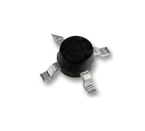
MINICIRCUIT – MINI CIRCUIT ERA-5SM High-Dynamic-Range MMIC Amplifier, DC to 4 GHz
MAXIMUM DYNAMIC POWER (dBm) RANGE at 2 GHz* at 2 GHz*
features
low thermal resistance miniature microwave amplifier available in drop-in & surface mount (sm) versions frequency range, to 8 GHz, usable to 10 GHz to 18.5 dBm typ. (16.5 dBm min) output power
Note: Prefix letter (optional) designates assembly location. Suffix letters (optional) are for wafer identification.
C. D. Aqueous washable at 1 GHz for fu is the upper frequency limit for each model as shown in the table. Gain, gain flatness, and VSWR are specified at 1.5 GHz. Low frequency cutoff determined by external coupling capacitors. Environmental specifications and re-flow soldering information available in General Information Section. Units are non-hermetic unless otherwise noted. For details on case dimensions & finishes see “Case Styles & Outline Drawings”. Prices and Specifications subject to change without notice. For Quality Control Procedures see Table of Contents, Section 0, “Mini-Circuits Guarantees Quality” article. For Environmental Specifications see Amplifier Selection Guide. Model number designated by alphanumeric code marking. ERA-SM models available on tape and reel. Permanent damage may occur if any of these limits are exceeded. These ratings are not intended for continuous normal operation. Supply voltage must be connected to pin 3 through a bias resistor in order to prevent damage. See “Biasing MMIC Amplifiers” in minicircuits.com/ application.html. Reliability predictions are applicable at specified current & normal operating conditions.
MTTF vs. Junction Temp. (For all ERA Models except ERA-5, ERA-5SM)
10 of each 10 of each 10 of each 10 of each 10 of each 5SM, 6SM NSN GUIDE
For Custom Versions Of Standard Models Consult Our Applications Dept.
Manufacturer:Electronic Components
Datasheet:Others/ERA-5SM.pdf


